modernization adapter - fireye fireye 192su3 adapter enables users to easily upgrade many older...
TRANSCRIPT

1
DESCRIPTIONThe Fireye 192SU3 adapter enables users to easily upgrade many older style 25SU3 controls to thedigital Fireye 25SU3-2100 Flame Safeguard Amplifier. The 192SU3 adapter contains the AC andDC power supplies required to allow the 25SU3-2100 control (24 vdc) to be compatible with the fol-lowing Fireye scanners: 45UV5, 45RM1, 45RM2, 45RM4, 45FS1, 45UVFS1.
The 192SU3 adapter is electrically and mechanically compatible with the older style wiring racksused with earlier 25SU3 controls, (rack P/N 60-1499, 60-1706, and European 60E5527 and similarracks). Little or no modifications are required to the original rack wiring.
25SU3 CONTROL TO BE REPLACED: ADAPTER MODEL REQUIRED TO UPDATE TO 25SU3-2100:
25SU3-4163
192SU3-2120 (120 VAC)
25SU3-4167(T)
25SU3-4170
25SU3-4172
25SU3-5172
25SU3-4164
192SU3-2220 (220 VAC)25SU3-4168(T)
25SU3-4171
25SU3-5173
MODERNIZATIONADAPTER
For 25SU3-2100 ControlP/N 192SU3-2120 (120V)P/N 192SU3-2220 (220V)
CU-36APRIL 11, 2013

2
Table of Contents
DESCRIPTION........................................................................................................................................................ 1
SPECIFICATIONS .................................................................................................................................................. 3
INSTALLATION ..................................................................................................................................................... 3
GENERAL APPLICATION NOTES ...................................................................................................................... 4
SPECIFIC APPLICATION NOTES........................................................................................................................ 5
60-1706 Rack, 25SU3-4163, -4167, -4170, -5172, -5173 Controls ................................................................ 5
60-1499-2 Wiring Rack, 25SU3-4163, -4167, -4170 Controls ..................................................................... 10
60-1499-11 Wiring Rack, 25SU3-4163, -4167, -4170 Controls .................................................................... 13
Using the Model C9707 Flame Scanner......................................................................................................... 16
60E5527 (or similar) European Rack............................................................................................................. 17
REMOTE FLAME SIGNAL METER .................................................................................................................. 20
MARGINAL ALARM RELAY............................................................................................................................. 20
RACK TERMINAL CROSS REFERENCE ......................................................................................................... 21

3
SPECIFICATIONS
ELECTRICAL SUPPLY
192SU3-2120 120 VAC (+10%, - 15%), 50/60 HZ
192SU3-2220 220 VAC (+10%, - 15%), 50/60 HZ
INTERNAL FUSE
P/N 23-184 1.6 AMP, 250V, Wickman TR5, #19370-053-K
ENVIRONMENTAL
Storage Temperature: Minimum: - 20 C Maximum: + 80 C
Operating Temperature: Minimum: - 20 C
Maximum: + 60 C
Humidity: Maximum 85% RH (Relative Humidity) Non condensing
DIMENSIONS
Height: 6.06 inches (15.4 cm)
Width: 2.91 inches (7.4 cm)
Depth: 8.18 inches (20.8 cm)
Weight: 1.47 lb. (669 grams)
INSTALLATION OVERVIEWThis bulletin illustrates the upgrade of older Fireye controls originally installed in the following wir-ing racks: P/N 60-1706, 60-1499-2, 60-1499-11, 60E5527 and similar racks. If the older control wasinstalled in any other rack, please refer to the original wiring diagrams and compare the appropriatebackplane card connector pin-outs (e.g. PL29, PR31, etc.)
Fireye series 25SU3-5170, -5171, -5172, and -5173 controls may be upgraded using the 192SU3adapter, provided that one of the above listed racks was installed. If, however, these controls weremounted edge to edge (1 7/8” spacing), in an ECA 5100 Systems rack, then a new rack must be pur-chased (consult factory).
The following describes the general procedure for upgrading an older 25SU3 control to the 25SU3-2100 using the 192SU3 adapter:
1. Review the General Application Notes, and the Specific Application Notes and wiring dia-grams that pertain to your particular wiring rack. Determine what, if any, rack wiringchanges must be made. Implement any changes prior to installing the new control.
2. Slide the new 25SU3-2100 control into the adapter. Make sure that the amplifier connectorproperly mates with the adapter connector. Secure the amplifier to the adapter by tightening thetwo captive screws.
3. Remove the old 25SU3 control from the wiring rack.
Caution: Do not install the 192SU3 adapter into the wiring rack without first installing the 25SU3-2100 into the adapter (step 2).
4. Slide the adapter (with the 25SU3-2100 already installed) into the wiring rack making sure thatthe adapter connector properly mates with the wiring rack connector.
5. Program the 25SU3-2100 control per instruction bulletin CU-34.

4
FIGURE 1. REMOVING ADAPTER FROM THE RACK
Caution: Do not install the 192SU3 adapter into the wiring rack without first installing the25SU3-2100 into the adapter. To then install or remove the 192SU3 adapter / 25SU3-2100assembly into the wiring rack, use the adapter handle ONLY (labeled “Pull Handle”)! Usingthe amplifier handle may result in mechanical damage to the amplifier.
GENERAL APPLICATION NOTES:1. The 25SU3-2100 control offers a 4-20 mA output to drive an external flame signal meter. Instal-
lations using the 0-3 vdc, 0-20 mA, or bargraph meter output of older controls, must eitherreplace these with 4-20 mA meters, or modify the existing 0-3 vdc meter to accept a 4-20 mAoutput (refer to figure12).
2. The 25SU3-2100 control offers two user-programmable flame relay ON / OFF thresholds. Thisfunction replaces the sensitivity “A” and “B” potentiometers of older controls, and the “Thresh-old Select” input of the older 25SU3-5170 controls. Depending upon the wiring rack used, thiscircuit will require minor modification. Refer to the appropriate wiring diagram for details (seeSpecific Application Section).
3. The 25SU3-2100 control has one flame relay with two sets of SPDT contacts (RF1, RF2). Con-tact set RF1 is internally fused and should be used as the primary input to the burner manage-ment system. Contact set RF2 is to be used for indication only.
4. The 192SU3 adapter contains three PC board jumpers to assure backward compatibility, andallow for the future addition of Fireye 24 VDC flame scanners.
Jumper JP1 (“PL26/PL29”), shipped in position “PL29”: Allows compatibility for older systemsthat switched amplifier sensitivity (A and B) by applying an AC neutral wire to pin PL26, (Refer toP/N 60E5527 rack, pages 17-19).
Jumpers JP2 & JP3 (“24 vdc/120 vac”), shipped in position “120 vac”. Many older mountingracks did not have terminals to access the control’s internal 24 vdc circuitry. Access to 24 vdc is
USE THE ADAPTER HANDLE (NOT THE AMPLIFIER HANDLE) TO
REMOVE THE ADAPTER/AMPLIFIER ASSEMBLY FROM THE WIRING RACK

5
required if the user wants to operate a Fireye 24 vdc flame scanner (e.g. 45RM4, 45FS1, 45UVFS1,C9707). Jumpers JP2 & JP3 allow the user to select between a 24 vdc or a 120 vac output on theolder rack’s flame scanner power terminal(s). (Refer to P/N 60-1499-2, -11 racks, pages 10-15).
FIGURE 2. 192SU3 JUMPER AND FUSE LOCATION
SPECIFIC APPLICATION NOTESBefore installing the 192SU3 adapter and 25SU3-2100 control, read and understand the SpecificApplication Notes, and the “Original” and “Upgrade, 192SU3” wiring schematics for your particularFireye control type and wiring rack part number. Determine what, if any, wiring changes must bemade. Implement any changes prior to installing the adapter and new control.
SPECIFIC APPLICATION NOTES: P/N 60-1706 Wiring Rack and 25SU3-4163, -4167, -4170 Controls
Figure 3 illustrates the typical field wiring of a 25SU3-4163, -4167, -4170 control when origi-nally installed into a P/N 60-1706 two-position rack. Figure 5 illustrates the field wiring afterthe 192SU3 upgrade.
1. Flame Scanner Input. The 60-1706 wiring rack accepted two 25SU3-4163, -4167, -4170 con-trols (only one is shown). Terminals were available for two scanners per control, although thetwo scanner signal leads were both connected to the same amplifier pin (via rack terminals 14A& 14D) and the amplifier summed the signals.
With the adapter, you have two choices:
A. (Preferred) Separate the two scanner signal wires, connecting scanner “A” to rack terminal14A, and connecting scanner “B” to rack terminal 14B. The 25SU3-2100 will now indicateseparate scanner “A” and “B” inputs. You may duplicate the signal “summing” if desired whenprogramming the new control.
B. Leave the scanner signal wires as is: The 25SU3-2100 control will indicate the sum of thetwo scanner’s signal output as “Scanner A”.
2. Sensitivity Adjustment. The sensitivity adjustment potentiometers (A and B) of the old controlwere selected in one of the following three ways:
JUMPER JP1“PL26/PL29”
JUMPER JP3“SCANNER A
24 VDC/120 VAC”
JUMPER JP2“SCANNER B
24 VDC/120 VAC”
FUSE F1

6
a. S.P.D.T. relay or switch contacts were wired between rack terminals S3, S4, and S5. With theadapter, you must remove the wires from S3, S4, and S5 and install two of them between rack terminals S5 and FM1. An open circuit selects scanner logic option 1, a closed circuit selectsscanner logic option 2.-or-
b. The auxiliary relay contacts (RX or RY) within the old control were used as the S.P.D.T switchbetween rack terminals S3, S4, and S5. The auxiliary relay was energized by closing a contactbetween rack terminals L1 and 42. With the adapter, this circuit is unchanged. Adapter pc boardjumper JP3 remains in the “PL29” position.-or-
c. The auxiliary relay contacts (RX or RY) within the old control were used as the S.P.D.T switchbetween rack terminals S3, S4, and S5. The auxiliary relay was energized by closing a contactbetween rack terminals 43 and AX or AY. With the adapter, you must isolate this contact andconnect it to rack terminals S5 and FM1.
4. Flame Signal Meter (0-3 vdc). An external 0-3 vdc flame signal meter may have been wiredbetween rack terminals FM1 (-) and FM2 (+). With the adapter, the 25SU3-2100 outputs 4-20mA across these terminals. You must either replace the dc voltmeter with a mA meter, or modifythe dc meter per figure 12.
5. Flame Signal Meter (0-20 mA). An external 0-20 mA flame signal meter or recorder may havebeen wired between rack terminals FM3 (+) and FM4 (-). With the adapter, this output is no lon-ger available (see note 3 above).
6. Auxiliary Relays, RX, RY. The older controls contained internal auxiliary relays (RX and RY)not available in the 25SU3-2100 control. If RX or RY were used for any purpose other thanswitching amplifier sensitivity, their function must be duplicated externally.
7. C9707 Flame Scanner. If a model C9707 All-fuel flame scanner is going to be used, refer topage 16 for specific application details.
SPECIFIC APPLICATION NOTES: P/N 60-1706 Wiring Rack and 25SU3-5172, -5173 Controls:
Figure 4 illustrates the typical field wiring of a 25SU3-5172, -5173 when originally installed intoa P/N 60-1706 two-position rack. Figure 5 illustrates the field wiring after the 192SU3 upgrade.
1. Before installing the new control: Remove the jumper wire from rack terminals S4 andFM3 (pins PR6 and PL4) Remove any wires from rack terminals S5, SCB, and 2SC (pinsPR3, PR10, and PR11)
2. Flame Scanner Input. With the adapter, the signal inputs from two scanners will remain on ter-minals 14A and 14B.
3. Sensitivity Adjustment. The 25SU3-5172 control had two adjustable “Threshold” settings,selected by applying either 24 vdc or line voltage (AC) onto rack terminal “S5”.With the adapter, you must remove this wiring, and either install a dry contact between rack ter-minals “S5” and “FM1”, or apply line voltage to rack terminal 42 to select “Scanner LogicOption 2”.
4. Flame Signal Meter (0-3 vdc). An external 0-3 vdc flame signal meter may have been wiredbetween rack terminals C(-) and FM2 (+). With the adapter, the 25SU3-2100 outputs 4-20 mAacross terminals FM1 (-) and FM2 (+). You must either replace the dc voltmeter with a mA meter,or modify the dc meter per figure 12, and connect to rack terminals FM1 and FM2.
5. Flame Signal Meter (0-20 mA). An external 0-20 mA flame signal meter or recorder may havebeen wired between rack terminals FM3 (+) and AX (-). With the adapter, this output is no lon-ger available, (see note 4).
6. Flame Signal Bargraph Meter (P/N 61-5560). The P/N 61-5560 Bargraph meter was con-nected to rack terminals FM3, FM4, and C. This meter is not compatible with the adapter andnew control and should be replaced with a 4-20 mA meter connected to rack terminals FM1 andFM2.
7. Serial Communication. The 25SU3-5172,-5173 used rack terminals X3, X4, S4, and + (pinsPR13, PR14, PR6, and PR8) for serial communications. This function is not available with theadapter and new control.
8. C9707 Flame Scanner. If a model C9707 All-fuel flame scanner is going to be used, refer topage 16 for specific application details.

7
FIGURE 3. ORIGINAL WIRING DIAGRAM: 60-1706 RACK WITH 25SU3-4170 CONTROL
42
22
L1
L2
AF5
AF4
AF2
F5
F4
F3
1A
14A
14D
1B
FM3
5
S5
FM1
FM2
FLAMERELAY
MARGINALALARMRELAY
CHASSIS
SCANNER A
(BGC)SCANNER
(UV)
SCANNER B
RM
PL5
PL6
PR3
PL2
PL3
PR4
PR1
PL1
PR5
PL4
PL9
PL11
PL10
PL24
PL23
PR22
PR19
PR18
PR23
PL31
PL29
PR31
PR29
PL25FLAMERELAY
INTERLOCK
CHASSISPOSITIONINTERLOCK
FLAME SIGNALMETER
(+)(-)0-3VDC
POWER(120VAC)
SCANNER ASHUTTER
DIODE101-78
SCANNERCOMMON
POWER
SCANNER BSHUTTER
0-20mA
M3
M5
M4
RF1
24 VDC
EXTERNALWIRING
EXTERNALWIRING
60-1706 RACK 25SU3-4170 CONTROL
PR20LA
C
PR21LB
RF2
S3 PR2
S4 PR6
6
INPUT POWER 120VAC
NEUTRAL
SENSITIVITY “B”
SENSITIVITY “A”
SENSITIVITYSELECTORSWITCH
SIGNAL
(120VAC)
TO RECORDER
FM4 PL7
43 PL28
X5 PR15
X4 PR14
X3 PR13
Y5 PR17
Y4 PR25
Y3 PR16
(+)
(-)
15VDCPOWER TO RX, RY COIL
AUX.RELAYRX
AUXRELAYRY
RX
RY
AUXILIARY RELAYS
AYPR27
PL26
AXPL27
120VAC
NEUTRAL
NEUTRAL
AUXILIARYRELAYPOWERSUPPLY15VDC
RY
RX
AUX. RELAYRY
AUX.RELAYRX
RX/RY RELAYCOMMON
AUX. RELAYPOWER SUPPLY
“B”
“A”
Notes: 25SU3-4167 controls were wired similarly.120 VAC wiring shown. With 230 VAC controls, input power was to terminals “230” and “L2”.
OUTPUT

8
FIGURE 4. ORIGINAL WIRING DIAGRAM: 60-1706 RACK WITH 25SU3-5172 CONTROL
L1
L2
AF5
AF4
AF2
F5
F4
F3
1A
14A
14B
1B
FM3
5
S5
FM1
FM2
FLAMERELAY
MARGINALALARMRELAY
CHASSIS
SCANNER A
SCANNER
SCANNER B
RM
PL5
PL6
PR3
PL2
PL3
PR4
PR1
PL1
PR5
PL4
PL9
PL11
PL10
PL24
PL23
PR22
PR19
PR18
PR31
PR29
PL25FLAMERELAY
INTERLOCK
CHASSISPOSITIONINTERLOCK
(+)(-)0-3VDC
POWER(120VAC)
SCANNER ASHUTTER
SCANNER A & BCOMMON
POWER
SCANNER BSHUTTER
M3
M5
M4
RF1
24 VDC
EXTERNALWIRING
EXTERNALWIRING
60-1706 RACK 25SU3-5172 CONTROL
PR20LA
C
PR21LB
RF2
S4 PR6
6
INPUT POWER 120VAC
SIGNAL A
(120VAC)
FM4 PL7
43 PL28
_ PR28
X4 PR14
X3 PR13
(+)
ANALOGDATAENABLE
SERIALDATAREQUEST
AXPL27
NEUTRAL
TO TERMINAL C
SCANNER SIGNAL B
PR9
FROM METER
+PR8
FM5PL8
*Notes:
1. 25SU3-5170 control was wired similarly.
2. 120 VAC wiring shown. For 230 vac controls, input power was connected to terminal “230” and “L2”.
3. Four external input switches could be connected to the 25SU3-5172 control: “Threshold Select” to terminal S5 (PR3), “Disable Scanner B”to terminal SCB (PR10), “Disable Scanner A” to terminal 2SC (PR11), and “FFRT Select” to terminal +TC (PL15).
4. If the voltage source for the field input switches was +24 vdc (terminal FM3 (PL4)), terminal FM1 (PL2) was connected to terminal C (PL1).
5. If the voltage source for the field input switches was line voltage (terminal L1 (PR31)), terminal FM1 (PL2) was connected to terminal L2 (PR29).
6. Either analog data output or serial data output was available (not both).
7. If analog data output was required (0-3 vdc & 0-20 mA), terminal S4 (PR6) was connected to terminal FM3 (PL4), terminal FM5 (PL8)to terminal + (PR8), and terminal 43 (PL28) to terminal - (PR28).
SERIALDATA OUT
*
A
B THRESHOLD SELECT
FIELD INPUT RETURN
0-20mARETURN (-)
SERIALDATA OUT
2SCPR11
SCBPR10
+TCPL15*3 1S
4S
DIS
DIS
*
FFRT SELECT
DISABLE SCANNER B
DISABLE SCANNER A
0-20mASUPPLY
TO 61-5560BARGRAPH
OUTPUT
*3
*3
*5, 7
*2
*2
*7
*6, 7
*3
*4, 5
*4
*4, 7
*7
*7

9
FIGURE 5. UPGRADE WIRING DIAGRAM: 192SU3 ADAPTER AND 60-1706 RACK
SCB
2SC
42
22
L1
L2
AF5
AF4
AF2
F5
F4
F3
1A
14A
14D
14B
LB
1B
FM3
5
6
S5
FM1
FM2
FLAMERELAY
MARGINALALARMRELAY
RS485COMM.
CHASSIS
SCANNER A
(BGC)SCANNER A
(UV)
SCANNER B
SCANNER B
RF1-1
RF2-2
RM-2
COMM B
COMM A
PL5
PL6
PR3
PL2
PL3
PR4
PR1
PL1
PR9
PR21
PR5
PL4
PL9
PL11
PL10
PL24
PL23
PR22
PR19
PR18
PR10
PR11
PL31
PL29
PR31
PR29
PL25FLAMERELAY
INTLK
CHASSISPOSITIONINTERLOCK
SCANNERLOGICOPTION
(NOTE 2)
FLAME SIGNALMETER
(+)(-)4-20mA
POWER(120VAC)SCANNER ASHUTTER
DIODE101-78
SCANNERCOMMON
SIGNAL
POWER(120VAC)SCANNER BSHUTTER
SCANNERPOWER(24VDC)
PL26
M3
M5
NEUTRAL
SCANNERLOGICOPTION
12
120VAC
12
(NOTE 2)
M4
D26
D24
D22
Z22
Z24
Z26
Z18
D20
Z20
D16
D14
RF2-1
RM-1
RF1-2 F2
1.5A
Z16
D4
Z4
D12
Z12D30
Z14
D6
D2
COMMON
Z2
Z6
D30D8
Z8 D28
SCANNER B
JP2
24 VDC
120VAC
24 VDCF1
1.6A
TO PL2
TO PR3
TO JP2,JP3
JP1
120 VACP.S.
24VDCP.S.TO JP2, JP3 -
+
EXTERNALWIRING
EXTERNALWIRING
60-1706 RACK192SU3 ADAPTER
25SU3-2100 CONTROL
SCANNER A
JP3
24 VDC
120VACPR20LA
ELECTRONICCIRCUIT
C
INPUT POWER 120VAC
NEUTRAL
Note 1: 120 VAC wiring shown. For 230 VAC Controls, input power is connected to terminals “230” and “L2”.Note 2: Scanner logic option may be selected in several ways. Refer to specific applicationnotes section.Note 3: Marginal alarm relay (RM) is shown de-energized. Refer to page 20 for additionalinformation.
OUTPUT

10
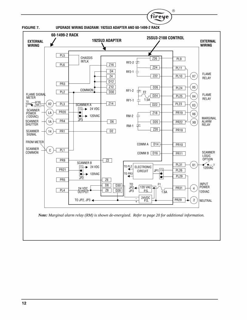
SPECIFIC APPLICATION NOTES: P/N 60-1499-2 Wiring Rack and 25SU3-4163, -4167, -4170 Controls
Figure 6 illustrates the typical field wiring of a 25SU3-4163, -4167, -4170 when originallyinstalled into a 60-1499-2 two position rack. Figure 7 illustrates the field wiring after the192SU3 upgrade.
1. Flame Scanner Input. The 60-1499-2 wiring rack accepted two 25SU3-4163, -4167, -4170controls (only one is shown). Terminals were available for only one scanner per control. If twoscanner were used, the scanner shutter leads (1), and power leads (L or P) were switched in andout of the circuit via an external relay or switch.With the adapter, this circuitry is not changed. The 25SU3-2100 control will indicate the signaloutput of the connected scanner as “Scanner A”.
2. Sensitivity Adjustment. The sensitivity adjustment potentiometers (A and B) of the old controlwere selected by applying 120 vac to rack terminal X1. With 120 vac present on X1, the auxil-iary relay (RX) was energized, selecting sensitivity “A”.With the adapter, this circuitry is not changed. The adapter pc board jumper JP3 remains in the“PL29” position. When 120 vac is applied to rack terminal X1, the 25SU3-2100 will select“Scanner Logic Option 2”. When voltage is removed from X1, the 25SU3-2100 will select“Scanner Logic Option 1”.
3. Flame Signal Meter (0-3 vdc). An external 0-3 vdc flame signal meter may have been wiredbetween rack terminals C (-) and X2 (+). With the adapter, the 25SU3-2100 outputs 4-20 mAacross these terminals. You must either replace the dc voltmeter with a mA meter, or modify thedc meter per figure 12.
4. Scanner Power. The 192SU3 adapter pc board jumper JP3 is shipped from the factory in the“120 vac” position, supplying 120 vac on rack terminal “LA” for use with high voltage scanners(e.g. 45UV5, 45RM1, or 45RM2). If the user wishes to connect a 24 vdc scanner (e.g. 45RM4,45FS1, or 45UVFS1) adapter pc board jumper JP3 must be placed in the 24 vdc position.
5. C9707 Flame Scanner. If a model C9707 All-fuel flame scanner is going to be used, refer topage 16 for specific application details.

11
FIGURE 6. ORIGINAL WIRING DIAGRAM: 60-1499-2 RACK WITH 25SU3-4170 CONTROL
X1
4
2
X4
X3
1A
14
X2
MARGINALALARMRELAY
CHASSIS
SCANNER
SCANNER
RM
PL5
PL6
PR3
PL2
PL3
PR4
PR1
PL1
PR5
PL4
PL9
PL11
PL10
PL24
PL23
PR22
PR19
PR18
PR23
PL31
PL29
PR31
PR29
PL25FLAMERELAY
INTERLOCK
(+)(-)0-3VDC
POWER(120VAC)
SCANNER SHUTTER
SCANNERCOMMON
X6
RF1
24 VDC
EXTERNALWIRING
EXTERNALWIRING
60-1499-2 RACK 25SU3-4170 CONTROL
PR20LA
C
PR21
RF2
PR2
PR6
INPUT POWER 120VAC
NEUTRAL
SENSITIVITY “B”
SENSITIVITY “A”
SIGNAL
PL7
PR15
PR14
PR13
PR17
PR25
PR16
RX
RY
AUXILIARY RELAY RX
PR27
PL26
PL27
120VAC
NEUTRAL
NEUTRAL
AUXILIARYRELAYPOWERSUPPLY15VDC
AUX.RELAYRX
SENSITIVITYSELECTION
TO TERM C
FROM METER
PL2815 VDC TO RX COIL
A
B
AUXILIARY RELAY RY
120VAC
X7
FLAMERELAY
X8
X5
Note: 25SU3-4163, -4167 controls were wired similarly.
OUTPUT
12
FIGURE 7. UPGRADE WIRING DIAGRAM: 192SU3 ADAPTER AND 60-1499-2 RACK
X1
4
X7
X5
X4
X3
1A
14
X2
FLAMERELAY
MARGINALALARMRELAY
CHASSIS
SCANNER
SCANNER
RF1-1
RF2-2
RM-1
INPUT
COMM B
COMM A
PL5
PL6
PR3
PL2
PL3
PR4
PR1
PL1
PR9
PR21
PR5
PL4
PL9
PL11
PL10
PL24
PL23
PR22
PR19
PR18
PR10
PR11
PL31
PL29
PR31
PR29
PL25 FLAMERELAY
INTLK
FLAME SIGNALMETER
(+)(-)4-20MA
POWER(120VAC)SCANNER SHUTTER
SCANNERCOMMON
PL26
X6
POWER 120VAC
NEUTRAL
SCANNERLOGICOPTION
12
120VAC
X8
D26
D24
D22
Z22
Z24
Z26
Z18
D20
Z20
D16
D14
RF2-1
RM-2
RF1-2 F2
1.5A
Z16
D4
Z4
D12
Z12D30
Z14
D6
D2
COMMON
Z2
Z6
D30D8
Z8 D28
SCANNER B
JP2
24 VDC
120VAC
24 VDCF1
1.6A
TO PL2
TO PR3
TO JP2,JP3
JP1
120 VACP.S.
24VDCP.S.TO JP2, JP3 -
+
EXTERNALWIRING
EXTERNALWIRING
60-1499-2 RACK192SU3 ADAPTER
25SU3-2100 CONTROL
SCANNER A
JP3
24 VDC
120VACPR20LA
ELECTRONICCIRCUIT
C
TOTERMC
SIGNAL
FROM METER
2
OUTPUT
Note: Marginal alarm relay (RM) is shown de-energized. Refer to page 20 for additional information.

13
SPECIFIC APPLICATION NOTES: P/N 60-1499-11 Wiring Rack and 25SU3-4163, 4167, 4170 Controls:
Figure 8 illustrates the typical field wiring of a 25SU3-4163, -4167, -4170 when originally installedinto a 60-1499-11 two position rack. Figure 9 illustrates the field wiring after the 192SU3 upgrade.
1. Flame Scanner Input. The 60-1499-11 wiring rack accepted two 25SU3-4163, -4167, -4170 con-trols (only one is shown). Terminals were available for two scanner per control, although the twoscanner signal leads were both connected to rack terminal 14.With the adapter, this circuitry is not changed. The 25SU3-2100 control will indicate the sum of thetwo scanner’s signal output as “Scanner A”.
2. Sensitivity Adjustment. The sensitivity adjustment potentiometers (A and B) of the old controlwere selected by applying 120 vac to rack terminal X5. With 120 vac present on X5, the auxiliaryrelay (RX) was energized, selecting sensitivity “A”.With the adapter, this circuitry is not changed. The adapter pc board jumper JP3 remains in the“PL29” position. When 120 vac is applied to rack terminal X5, the 25SU3-2100 will select “Scan-ner Logic Option 2”. When voltage is removed from X5, the 25SU3-2100 will select “ScannerLogic Option 1”.
3. Flame Signal Meter (0-3 vdc). An external 0-3 vdc flame signal meter may have been wiredbetween rack terminals C (-) and X8 (+). With the adapter, the 25SU3-2100 outputs 4-20 mA acrossthese terminals. You must either replace the dc voltmeter with a mA meter, or modify the dc meterper figure 12.
4. Scanner Power. The 192SU3 adapter pc board jumpers JP2 and JP3 are shipped from the factory inthe “120 vac” position, supplying 120 vac on rack terminals “X1” and “LA” for use with high volt-age scanners (e.g. 45UV5, 45RM1, or 45RM2). If the user wishes to connect 24 vdc scanners (e.g.45RM4, 45FS1, or 45UVFS1) JP2 and / or JP3 must be placed in the 24 vdc position.
5. C9707 Flame Scanner. If a model C9707 All-fuel flame scanner is going to be used, refer to page16 for specific application details.

14
FIGURE 8. ORIGINAL WIRING DIAGRAM: 60-1499-11 RACK WITH 25SU3-4170 CONTROL
X5
4
2
X4
X3
1A
14
X2
X8
MARGINALALARMRELAY
CHASSIS
SCANNER A
SCANNER
SCANNER B
RM
PL5
PL6
PR3
PL2
PL3
PR4
PR1
PL1
PR5
PL4
PL9
PL11
PL10
PL24
PL23
PR22
PR19
PR18
PR23
PL31
PL29
PR31
PR29
PL25FLAMERELAY
INTERLOCK
(+)(-)0-3VDC
POWER(120VAC)
SCANNER ASHUTTER
SCANNERCOMMON
POWER
SCANNER BSHUTTER
X6
X7
RF1
24 VDC
EXTERNALWIRING
EXTERNALWIRING
60-1499-11 RACK 25SU3-4170 CONTROL
PR20LA
C
PR21X1
RF2
PR2
PR6
INPUT POWER 120VAC
NEUTRAL
SENSITIVITY “B”
SENSITIVITY “A”
SIGNAL A & B
(120VAC)
PL7
PR15
PR14
PR13
PR17
PR25
PR16
RX
RY
AUXILIARY RELAY RX
PR27
PL26
PL27
120VAC
NEUTRAL
NEUTRAL
AUXILIARYRELAYPOWERSUPPLY15VDC
AUX.RELAYRX
SENSITIVITYSELECTION
TO TERM C
FROM METER
PL2815 VDC TO RX COIL
AB
AUXILIARY RELAY RY
120VAC
Note: 25SU3-4163, -4167 controls were wired similarly.
OUTPUT

15
FIGURE 9. UPGRADE WIRING DIAGRAM: 192SU3 ADAPTER AND 60-1499-11 RACK
X5
4
2
X4
X3
1A
14
X1
X2
X8
FLAMERELAY
MARGINALALARMRELAY
CHASSIS
SCANNER A
SCANNER A
SCANNER B
RF1-1
RF2-2
RM-1
COMM B
COMM A
PL5
PL6
PR3
PL2
PL3
PR4
PR1
PL1
PR9
PR21
PR5
PL4
PL9
PL11
PL10
PL24
PL23
PR22
PR19
PR18
PR10
PR11
PL31
PL29
PR31
PR29
PL25FLAMERELAY
INTLK
FLAME SIGNALMETER
(+)(-)4-20mA
POWER(120VAC)SCANNER ASHUTTER
SCANNERCOMMON
POWER(120VAC)SCANNER BSHUTTER
PL26
X6
SCANNERLOGICOPTION
12
120VAC
X7
D26
D24
D22
Z22
Z24
Z26
Z18
D20
Z20
D16
D14
RF2-1
RM-2
RF1-2 F2
1.5A
Z16
D4
Z4
D12
Z12D30
Z14
D6
D2
COMMON
Z2
Z6
D30D8
Z8 D28
SCANNER B
JP2
24 VDC
120VAC
24 VDCF1
1.6A
TO PL2
TO PR3
TO JP2,JP3
JP1
120 VACP.S.
24VDCP.S.TO JP2, JP3 -
+
EXTERNALWIRING
EXTERNALWIRING
60-1499-11 RACK192SU3 ADAPTER
25SU3-2100 CONTROL
SCANNER A
JP3
24 VDC
120VACPR20LA
ELECTRONICCIRCUIT
C
INPUT POWER 120VAC
NEUTRAL
TOTERMC
& B SIGNAL
FROM METER
OUTPUT
Note: Marginal alarm relay (RM) is shown de-energized. Refer to page 20 for additional information.
16
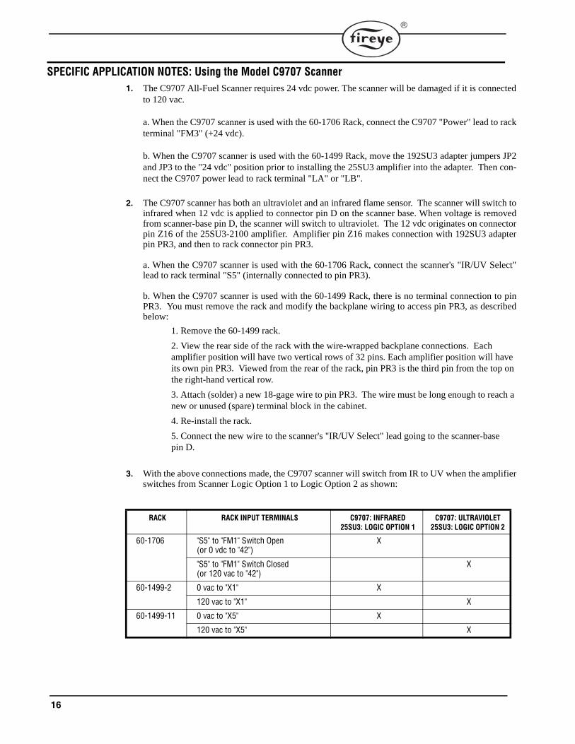
SPECIFIC APPLICATION NOTES: Using the Model C9707 Scanner 1. The C9707 All-Fuel Scanner requires 24 vdc power. The scanner will be damaged if it is connected
to 120 vac.
a. When the C9707 scanner is used with the 60-1706 Rack, connect the C9707 "Power" lead to rackterminal "FM3" (+24 vdc).
b. When the C9707 scanner is used with the 60-1499 Rack, move the 192SU3 adapter jumpers JP2and JP3 to the "24 vdc" position prior to installing the 25SU3 amplifier into the adapter. Then con-nect the C9707 power lead to rack terminal "LA" or "LB".
2. The C9707 scanner has both an ultraviolet and an infrared flame sensor. The scanner will switch toinfrared when 12 vdc is applied to connector pin D on the scanner base. When voltage is removedfrom scanner-base pin D, the scanner will switch to ultraviolet. The 12 vdc originates on connectorpin Z16 of the 25SU3-2100 amplifier. Amplifier pin Z16 makes connection with 192SU3 adapterpin PR3, and then to rack connector pin PR3.
a. When the C9707 scanner is used with the 60-1706 Rack, connect the scanner's "IR/UV Select"lead to rack terminal "S5" (internally connected to pin PR3).
b. When the C9707 scanner is used with the 60-1499 Rack, there is no terminal connection to pinPR3. You must remove the rack and modify the backplane wiring to access pin PR3, as describedbelow:
1. Remove the 60-1499 rack.
2. View the rear side of the rack with the wire-wrapped backplane connections. Each amplifier position will have two vertical rows of 32 pins. Each amplifier position will have its own pin PR3. Viewed from the rear of the rack, pin PR3 is the third pin from the top on the right-hand vertical row.
3. Attach (solder) a new 18-gage wire to pin PR3. The wire must be long enough to reach a new or unused (spare) terminal block in the cabinet.
4. Re-install the rack.
5. Connect the new wire to the scanner's "IR/UV Select" lead going to the scanner-base pin D.
3. With the above connections made, the C9707 scanner will switch from IR to UV when the amplifierswitches from Scanner Logic Option 1 to Logic Option 2 as shown:
RACK RACK INPUT TERMINALS C9707: INFRARED25SU3: LOGIC OPTION 1
C9707: ULTRAVIOLET25SU3: LOGIC OPTION 2
60-1706 "S5" to "FM1" Switch Open(or 0 vdc to "42")
X
"S5" to "FM1" Switch Closed(or 120 vac to "42")
X
60-1499-2 0 vac to "X1" X
120 vac to "X1" X
60-1499-11 0 vac to "X5" X
120 vac to "X5" X
17
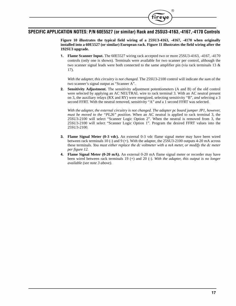
SPECIFIC APPLICATION NOTES: P/N 60E5527 (or similar) Rack and 25SU3-4163,-4167,-4170 Controls
Figure 10 illustrates the typical field wiring of a 25SU3-4163, -4167, -4170 when originallyinstalled into a 60E5527 (or similar) European rack. Figure 11 illustrates the field wiring after the192SU3 upgrade.
1. Flame Scanner Input. The 60E5527 wiring rack accepted two or more 25SU3-4163, -4167, -4170controls (only one is shown). Terminals were available for two scanner per control, although thetwo scanner signal leads were both connected to the same amplifier pin (via rack terminals 13 &17).
With the adapter, this circuitry is not changed. The 25SU3-2100 control will indicate the sum of thetwo scanner’s signal output as “Scanner A”.
2. Sensitivity Adjustment. The sensitivity adjustment potentiometers (A and B) of the old controlwere selected by applying an AC NEUTRAL wire to rack terminal 3. With an AC neutral presenton 3, the auxiliary relays (RX and RY) were energized, selecting sensitivity “B”, and selecting a 3second FFRT. With the neutral removed, sensitivity “A” and a 1 second FFRT was selected.
With the adapter, the external circuitry is not changed. The adapter pc board jumper JP1, however,must be moved to the “PL26” position. When an AC neutral is applied to rack terminal 3, the25SU3-2100 will select “Scanner Logic Option 2”. When the neutral is removed from 3, the25SU3-2100 will select “Scanner Logic Option 1”. Program the desired FFRT values into the25SU3-2100.
3. Flame Signal Meter (0-3 vdc). An external 0-3 vdc flame signal meter may have been wiredbetween rack terminals 10 (-) and 9 (+). With the adapter, the 25SU3-2100 outputs 4-20 mA acrossthese terminals. You must either replace the dc voltmeter with a mA meter, or modify the dc meterper figure 12.
4. Flame Signal Meter (0-20 mA). An external 0-20 mA flame signal meter or recorder may havebeen wired between rack terminals 19 (+) and 20 (-). With the adapter, this output is no longeravailable (see note 3 above).

18
FIGURE 10. ORIGINAL WIRING DIAGRAM: 60E5527 RACK WITH 25SU3-4170 CONTROL
2
SENSITIVITYSELECTION
A
1
7
6
11
13
9
MARGINALALARMRELAY
CHASSIS
UV SCANNER
SCANNER
RM
PL5
PL6
PR3
PL2
PL3
PR4
PR1
PL1
PR5
PL4
PL9
PL11
PL10
PL24
PL23
PR22
PR19
PR18
PR23
PL31
PL29
PR31
PR29
PL25FLAMERELAY
INTERLOCK
(+)(-)0-3VDC
POWER(120VAC)
SCANNER ASHUTTER
BGC SCANNERCOMMON
5
RF1
24 VDC
EXTERNALWIRING
EXTERNALWIRING
60E5527 RACK 25SU3-4170 CONTROL
PR2012
14
PR21
RF2
PR2
PR6
INPUT POWER 120VAC/230VA
NEUTRAL
SENSITIVITY “B”
SENSITIVITY “A”
SIGNAL
PL7
PR15
PR14
PR13
PR17
PR25
PR16
RX
RY
AUXILIARY RELAY RX
PR27
PL26
PL27
120VAC
NEUTRAL
NEUTRAL
AUXILIARYRELAYPOWERSUPPLY15VDC
PL2815 VDC TO RX COIL
B
AUXILIARY RELAY RY
A
FLAMERELAY
B
810
17
BGC
TOPR25
DIODE
UV SCANNERCOMMON
18
BGC SCANNER POWER(120VAC)
UV SCANNER SHUTTER
16
15
20
190-20 mATO RECORDER
PL15
TO TERMINAL 10
F.F.R.T.
330 μF/53V
C
4
(NEUTRA3
UV
+
-
CAPACITOR
Note: 25SU3-4163, -4167 controls were wired similarly.
OUTPUT

19
FIGURE 11. UPGRADE WIRING DIAGRAM: 192SU3 ADAPTER AND 60E5527 RACK
3
2
1
C
B
A
8
7
6
11
13
17
16
15
19
10
9
FLAMERELAY
MARGINALALARMRELAY
CHASSIS
BGC SCANNER
(BGC)SCANNER
(UV)
UV SCANNER
RF1-1
RF2-2
RM-1
COMM B
COMM A
PL5
PL6
PR3
PL2
PL3
PR4
PR1
PR9
PR21
PR5
PL4
PL9
PL11
PL10
PL24
PL23
PR22
PR19
PR18
PR10
PR11
PL29
PR31
PR29
PL25FLAMERELAY
INTLK
FLAME SIGNALMETER
(+)(-)4-20mA
POWER(120VAC)
SHUTTER
DIODE101-78
SCANNER COMMON
UV SCANNER SHUTTER
SCANNERPOWER
(24VDC)
PL26
5
NEUTRAL
SCANNERLOGICOPTION
12
120VAC
4
D26
D24
D22
Z22
Z24
Z26
Z18
D20
Z20
D16
D14
RF2-1
RM-2
RF1-2 F2
1.5A
Z16
D4
Z4
D12
Z12D30
Z14
D6
D2
COMMON
Z2
Z6
D30D8
Z8 D28
SCANNER B
JP2
24 VDC
120VAC
24 VDCF1
1.6A
TO PL2
TO PR3
TO JP2,JP3
JP1
120 VACP.S.
24VDCP.S.TO JP2, JP3 -
+
EXTERNALWIRING
EXTERNALWIRING
60E5527 RACK192SU3 ADAPTER
25SU3-2100 CONTROL
SCANNER A
JP3
24 VDC
120VACPR2012
ELECTRONICCIRCUIT
14
INPUT POWER
NEUTRAL
BGC SCANNER
SIGNAL
PL1
UV SCANNER COMMON 18
BGC
(120VAC)
20 PL7
PL31
OUTPUT
Note 1: 120 VAC wiring shown.Note 2: Marginal alarm relay (RM) is shown de-energized. Refer to page 20 for additional information.Note 3: See application note 2, page 17 regarding jumper JP1.
POWER

20
Remote Flame Signal MeterTo allow an existing 0-3 vdc Flame Signal Meter to be used with a 4-20 mA output, install a 150ohm, 1/4 watt resistor across the meter (+) and (-) terminals. This will result in a 0.6 - 3.0 vdc metermovement. If a 0.0 - 2.4 vdc meter movement is preferred, in addition to the resistor, connect a diodein series with the meter (+) terminal (see figure 12). Alternately, you may replace the 0-3 vdc meterwith a 4-20 mA Fireye meter, P/N 38-96.
FIGURE 12.
Marginal Alarm Relay (RM)The marginal alarm relay (RM) is a pre-trip alarm, providing notification of a deteriorating flamesignal such as may be caused by poor combustion or a contaminated scanner lens. The RM contactsin the 25SU3-2100 operate the same as in the older controls once the flame relay (RF) is energized.With the flame relay (RF) de-energized, the RM contacts in the two controls are opposite per the following table. The "PR" designation refers to the pc board pins that access the RM contacts.
AMPLIFIER TYPE FLAME SIGNAL LEVEL
SIGNAL BELOW RF THRESHOLD
RF ENERGIZED, BUT SIGNAL MARGINAL
RF ENERGIZED AND SIGNAL NOT MARGINAL
25SU3-4170 RM COIL DE-ENERGIZED DE-ENERGIZED ENERGIZED
PR22-PR19 CLOSED CLOSED OPEN
PR22-PR18 OPEN OPEN CLOSED
25SU3-2100 RM COIL DE-ENERGIZED ENERGIZED DE-ENERGIZED
PR22-PR19 OPEN CLOSED OPEN
PR22-PR18 CLOSED OPEN CLOSED
®
L A M E S I G NALF
0-3VDC FIREYE METER
( + ) ( _ )
( + ) ( _ )
150 Ohm
1/4 WATT RESISTOR
(REQUIRED)
DIODE(OPTIONAL)
4 -20 mA FROM 25SU3-2100 CONTROL

21
FIGURE 13. RACK TERMINAL CROSS REFERENCE
PC BoardPin Nos.
Wiring Rack Terminal Numbers Amplifier Function
Rack p/n60-1499-2
Rack p/n60-1499-11
Rack p/n60-1706
Rack p/n60E5527
Original25SU3-4170
Original25SU3-5172
New25SU3-2100
PL1 C C C 14 Scanner Common
Scanner Common
Scanner Common
PL2 FM1 10 Meter Common
Field Input Return
Meter Common,4-20mA(-)
PL3 X2 X8 FM2 9 3V Meter+ 3V Meter+ 4-20mA(+)
PL4 FM3 19 0-20 mA + 0-20 mA +24 vdc
24 vdc Scanner Power
PL5 5 Position Interlock
PositionInterlock
Position Interlock
PL6 6 PositionInterlock
Position Interlock
Position Interlock
PL7 FM4 20 0-20 mA - 61-5560 bargraph signal
PL8 FM5 Analog data
PL9 AF5 C RF1 (NC) RF1 (NC) RF2 (NC)
PL10 X7 AF2 A RF1 (NO) RF1 (NO) RF2 (NO)
PL11 X8 AF4 B RF1(Com) RF1(Com) RF2(Com)
PL13 X3 Serial Data Request
PL14 X4 Serial Data Request
PL15 +TC * FFRT Select
PL23 X3 X3 F3 6 RF2 (NO) RF2 (NO) RF1 (NO)
PL24 X5 F5 8 RF2 (NC) RF2 (NC) RF1 (NC)
PL25 X4 X4 F4 7 RF2(Com) RF2(Com) RF1(Com)
PL26 2 2 * 3 RX coil - Scanner Logic Option
PL27 * * AX * RX coil + 0-20 mA -
PL28 * * 43 * 16 vdc for RX, RY
Analog data enable
PL29 2 2 22 1 RX,RY coil common
Scanner Logic Option
PL31 X1 X5 42 2 Aux. Relay PS input
Scanner Logic Option
NOTE 1: Refer to Specific Application Notes section for additional information.NOTE 2: Blank section indicates no rack connection.NOTE 3: An asterisk (*) indicates a rack connection without external (terminal) access.

22
RACK TERMINAL CROSS REFERENCE continued
PC BoardPin Nos.
Wiring Rack Terminal Numbers Amplifier Function
Rack p/n60-1499-2
Rack p/n60-1499-11
Rack p/n60-1706
Rack p/n60E5527
Original25SU3-4170
Original25SU3-5172
New25SU3-2100
PR1 14 14 14A 13 Scanner signal Scanner “A” signal
Scanner “A” signal
14D Scanner signal
PR2 * * S3 * Sensitivity “B”
PR3 * * S5 * Sensitivity “A” Threshold Select
Scanner Logic Option
PR4 1A 1A 1A 11 Scanner “A” shutter
Scanner “A” shutter
Scanner “A” shutter
PR5 X2 1B 15 Scanner “B” shutter
Scanner “B” shutter
Scanner “B” shutter
PR6 * * S4 * Sensitivity (common)
Serial Data Out
PR8 ( + ) Serial Data Out
PR9 14B Scanner “B” signal
Scanner “B” signal
PR10 SCB Disable Scanner “B”
RS485 Comm. A
PR11 2SC Disable Scan-ner “A”
RS485 Comm. B
PR13 * * X3 * RX (NO) Serial Data Request
PR14 * * X4 * RX (Com) Serial Data Request
PR15 * * X5 * RX (NC)
PR16 Y3 * RY (NO)
PR17 Y5 RY (NC)
PR18 M3 RM (NO) RM (NO) RM (NC)
PR19 X6 X6 M5 5 RM (NC) RM (NC) RM (NO)
PR20 LA LA LA 12 Scanner “A” power
Scanner “A” power
Scanner “A” power
PR21 X1 LB 16 Scanner “B” power
Scanner “B” power
Scanner “B” power
PR22 X8 X7 M4 4 RM (Com) RM (Com) RM (Com)
PR23 2 2 * 3 RY coil -
PR25 Y4 * RY (Com)
PR27 AY * RY coil +
PR28 ( - ) Analog Data Enable
PR29 2 2 L2 1 120 vac input neutral
120 vac input neutral
AC input neutral
PR31 4 4 L1 2 120 vac input hot
120 vac input hot
AC input hot
230 230 vac input hot
230 vac input hot
230 vac input hot
NOTE 1: Refer to Specific Application Notes section for additional information.NOTE 2: Blank section indicates no rack connection.NOTE 3: An asterisk (*) indicates a rack connection without external (terminal) access.

23

24
NOTICEWhen Fireye products are combined with equipment manufactured by others and/or integrated intosystems designed or manufactured by others, the Fireye warranty, as stated it its General Terms andConditions of Sale, pertains only to the Fireye products and not to any other equipment or to thecombined system or its overall performance.
WARRANTIESFIREYE guarantees for one year from the date of installation or 18 months from date of manufactureof its products to replace, or, at its option, to repair any product or part thereof (except lamps, elec-tronic tubes and photocells) which is found defective in material or workmanship or which otherwisefails to conform to the description of the product on the face of its sales order. THE FOREGOINGIS IN LIEU OF ALL OTHER WARRANTIES AND FIREYE MAKES NO WARRANTY OFMERCHANTABILITY OR ANY OTHER WARRANTY, EXPRESS OR IMPLIED. Except asspecifically stated in these general terms and conditions of sale, remedies with respect to any productor part number manufactured or sold by Fireye shall be limited exclusively to the right to replace-ment or repair as above provided. In no event shall Fireye be liable for consequential or special dam-ages of any nature that may arise in connection with such product or part.
FIREYE CU-363 Manchester Road APRIL 11, 2013Derry, New Hampshire 03038 USA Supersedes August 10, 2005www.fireye.com