modern radiological postoperative diagnostics of the hip ... · modern radiological postoperative...
TRANSCRIPT
Modern Radiological Postoperative Diagnosticsof the Hip Joint in Children and AdultsModerne radiologische postoperative Diagnostikdes Hüftgelenks im Kindes- und Erwachsenenalter
Authors M.-A. Weber1, M. Egermann2, H. Thierjung1, J. K. Kloth1
Affiliations 1 Diagnostic and Interventional Radiology, Heidelberg University Hospital, Heidelberg, Germany2 Center for Orthopedics, Trauma Surgery and Spinal Cord Injury, Heidelberg University Hospital, Heidelberg, Germany
Key words
●" hip joint
●" surgery
●" postoperative imaging
●" joint replacement
●" osteonecrosis
●" developmental dysplasia ofthe hip
received 30.8.2014accepted 17.1.2015
BibliographyDOI http://dx.doi.org/10.1055/s-0034-1399232Published online: 6.3.2015Fortschr Röntgenstr 2015; 187:525–542 © Georg ThiemeVerlag KG Stuttgart · New York ·ISSN 1438-9029
CorrespondenceProf. Marc-André WeberUniversitätsklinik Heidelberg,Diagnostische undInterventionelle RadiologieIm Neuenheimer Feld 110D-69120 HeidelbergGermanyTel.: ++ 49/6221/5 6374 34Fax: ++ 49/6221/5 6266 [email protected]
Abstract!
The assessment of bone healing and loosen-ing of endoprosthesis material was long theprimary indication for postoperative projec-tion radiography and CT imaging of the hipjoint following trauma and endoprosthesisimplantation. With the increasing number ofjoint-preserving surgery, e. g. of surgical hipluxation and hip arthroscopy for the treat-ment of femoroacetabular impingement(FAI), high-resolution imaging of intra-articu-lar pathologies before and after surgery hasbecome increasingly important. In this re-view article, diagnostic imaging of the hipjoint is presented following common traumasurgery and orthopedic surgery interven-tions. The imaging modalities of projectionradiography, CT and MRI including directMR-arthrography are discussed with regardto their diagnostic capability in the post-operative assessment of the hip joint. Amongothers topics, imaging is discussed followinghip arthroplasty, following surgical hip luxa-tion and arthroscopic interventions for thetreatment of FAI, as well as following core de-compression for avascular necrosis of thefemoral head. Moreover, orthopedic inter-ventions of the hip joint in children and ado-lescents are presented and the dedicated re-porting of postoperative imaging is outlined.Key points:
▶ Consolidation of osteotomies and positionof implants should be assessed in post-operative imaging.
▶ MRI is useful for confirming correct articu-lation after treatment of congenital hip dis-location.
▶ Radiologically assessable complicationsafter total hip replacement are inlay wear,loosening, dislocation, periarticular ossifi-cations and infection.
▶ MRI can detect and classify pseudotumoursin cases of metal-metal pairing after totalhip replacement.
Citation Format:
▶ Weber MA, Egermann M, Thierjung H et al.Modern Radiological Postoperative Diagnos-tics of the Hip Joint in Children and Adults.Fortschr Röntgenstr 2015; 187: 525–542
Zusammenfassung!
Die Beurteilung von Knochenheilung und Implan-tatlockerung war über lange Zeit die Haupt-indikation der postoperativen Röntgen- undCT-Bildgebung des Hüftgelenks nach Trauma undendoprothetischem Gelenkersatz. Mit zuneh-mender Zahl gelenkerhaltender Eingriffe, z. B. derchirurgischen Hüftluxation und der Hüftge-lenkarthroskopie in der Therapie des femoro-acetabulären Impingements (FAI) gewinnt diehochauflösende Diagnostik intraartikulärer Pa-thologien präoperativ wie auch in der postope-rativen Bildgebung an Bedeutung. In dieserÜbersicht wird die bildgebende Diagnostik desHüftgelenks nach häufigen orthopädisch-unfall-chirurgischen Eingriffen vorgestellt. Es werdendie Modalitäten Projektionsradiografie, Compu-tertomografie und Magnetresonanztomografieeinschließlich der direkten MRT-Arthrografiehinsichtlich ihrer Wertigkeit in der postoperati-ven Diagnostik des Hüftgelenks diskutiert. Unteranderem werden die Befundinterpretation nachHüftendoprothetik, nach chirurgischer Hüftluxa-tion und arthroskopischer Operation bei FAI so-wie nach Anbohrung einer Hüftkopfnekrose be-sprochen. Zudem werden kinderorthopädischeEingriffe am Hüftgelenk vorgestellt und deren de-zidierte postoperative Bildbefundung skizziert.
Review 525
Weber M-A et al. Modern Radiological Postoperative… Fortschr Röntgenstr 2015; 187: 525–542
Thi
s do
cum
ent w
as d
ownl
oade
d fo
r pe
rson
al u
se o
nly.
Una
utho
rized
dis
trib
utio
n is
str
ictly
pro
hibi
ted.
Introduction!
This review article first addresses postoperative hip ima-ging in children before proceeding to the topics of imagingperformed following joint-preserving interventions as wellas hip-replacement surgeries (hip endoprosthesis).The underlying diseases relevant to imaging are explained, themost common surgical procedures introduced and the criteriafor evaluating or assessing the results in postoperative imaging,conventional radiographs, MRI and CT are discussed.
1. Postoperative hip imaging in children!
1.1 Slipped capital femoral epiphysisWith an incidence rate of 2–10/100 000 slipped capitalfemoral epiphysis (SCFE) is the most common hip diseasein children and adolescents [1]. This displacement of theepiphysis against the metaphysis (typically in the medio-dorsal direction) primarily affects children around the pre-pubescent growth spurt (from nine years old to the end ofgrowth) and has a male-to-female ratio of 2:1. It should benoted that approximately 50% of cases are bilateral [2, 3]. Inmost cases, the affected child is significantly overweight(> 97th percentile for age). The acute form is less commonthan the more frequently observed lenta form, thus makingimaging diagnostics important particularly when patientsexhibit clinically limited inner rotation (positive Drehmannsign) [2]. Radiographs show loosened epiphyseal junctions.The orthograde imaging of the femoral neck using theLauenstein method (hip flexion around 70° and abductionaround 50°) is critical for diagnosing SCFE. The Lauensteinview shows a flattened lateral convexity of the epiphysealjunction with the femoral head (●" Fig. 1) [1, 2]. For tiltingangles up to 30°, therapy consists of stabilizing with wiresor screws. Tilting angles above 30° require corrective os-teotomy, e. g. Imhäuser method, i. e. inflective and valgizingosteotomy of the proximal femur [1–3]. Following surgicaltreatment of SCFE, the radiologist’s task is to sufficientlyevaluate the position of implants and identify any malposi-tion (●" Fig. 2). It can be concluded that radiological diagnos-tics target the following points following the fixation ofSCFE:Report checklist
▶ Is there “secure” three-dimensional fixation of the epi-physis?
▶ Can intra-articular position of the implants be excluded?
▶ Treatment of the contralateral side or frequent examina-tion thereof due to the 50% risk of bilateral epiphysiolysisof the femoral head.
▶ Does radiological imaging show osseous consolidationfollowing corrective osteotomy sufficient for full weightto be placed on the joint?
▶ Evaluating the joint space and joint congruency.
▶ Follow-up examinations to exclude the development ofhip necrosis following closed/open reposition.
1.2 Perthes diseasePerthes disease is the idiopathic pediatric osteonecrosis ofthe femoral head which appears between the age of fiveand seven and occurs at a male-to-female ratio of 4:1. It is
bilateral in 15% of cases [4]. The key clinical symptoms arefrequently limping with limited mobility of the hips and, inrare cases, knee pain. It should be noted that inguinal hippain is the exception [5]. The extent of the femoral head in-volvement is classified into four Catterall grades on axial hipradiographs, group III and IV having an unfavorable prog-nosis and therefore requiring treatment. Risk signs highlysuggestive of an unfavorable course include, among otherfindings, lateralization of the epiphysis, lateral calcificationof the epiphysis and involvement of the metaphysis [4, 5].Loss of mobility, flection and abduction position, abductioncontracture and being overweight are clinical “head at risksigns”, the collective presence thereof indicating imminentirreversible damage to the femoral head. Radiological signsof Perthes disease are visible expansion of the joint space(initial stage according to Waldenström), densification ofthe femoral epiphysis (condensation stage), fragmentationof the osseous core of the femoral head (fragmentationstage) and mushrooming deformation of the femoral headin the late stage [5]. When risk signs appear (particularly la-teralization and lateral calcification), centering, i. e. the con-tainment of the femoral head to prevent further deforma-tion, by means of intertrochanteric varisation osteotomy orpelvic osteotomy according to Salter is recommended. Thecomplication of Perthes disease is the development of pre-arthritic deformation such as coxa plana and coxa magna,which can necessitate joint replacement during early adult-hood [4]. The goal of treatment is to preserve mobility,thereby allowing physiological regeneration to form a sphe-rical femoral head. Should early conservative measures,particularly physical therapy, fail to bring about the desiredsuccess, the centering of the femoral head and the rotatingin of the non-endangered portions of the main load zonecan be attempted through surgical therapy. When it comesto prognosis, age is of major importance, with a younger ageat the onset of the disease meaning better femoral "regen-eration" during the repair phase [5].The role of imaging is to provide stage classification, detectthe progress and the presence of bilateral involvement aswell as assess the correct position of the osteosynthesis ma-terial or the occurrence of implant failure following surgicaltreatment. Surgical methods for centering the hip joint incases of Perthes disease are intertrochanteric varisation os-teotomy for stage II through IV with “head at risk signs”(●" Fig. 3) and, if the patient is between the age of five andeight years, pelvic osteotomy, e. g. according to Salter in pa-tients exhibiting the aforementioned indications plus lim-itedmobility, and a valgization osteotomy (●" Fig. 4) for olderpatients experiencing pain, hinge abduction and fixed mal-alignment. In addition to femoral corrective osteotomy,pelvic osteotomy (e. g. according to Salter) has establisheditself as another standard method for achieving better con-tainment of the femoral head (see alsoHip dysplasia surgerywith corresponding diagrams and image examples in sub-section 1.4). To conclude, it is the radiologist’s task to checkfor the following when evaluating therapy performed totreat Perthes disease:Report checklist
▶ Development of the “head at risk”: signs
▶ Checking the contralateral side in bilateral cases(15% incidence rate)
Weber M-A et al. Modern Radiological Postoperative… Fortschr Röntgenstr 2015; 187: 525–542
Review526
Thi
s do
cum
ent w
as d
ownl
oade
d fo
r pe
rson
al u
se o
nly.
Una
utho
rized
dis
trib
utio
n is
str
ictly
pro
hibi
ted.

▶ In cases of surgical therapy:
▶ Have the osteotomy spaces consolidated?
▶ Correct position of implants. Can intra-articular posi-tion of implant material be excluded?
▶ Documentation of surgery success or the targeted im-provement of containment
▶ Is implant failure present?
1.3 Congenital hip luxation/hip dysplasiaDysplasia and luxation of the hip are morphological entitiesof various degrees [6]. Congenital hip luxation (Graf stage 3and 4) is treated in-house through repositioning and settinga plaster cast (pelvic-leg cast/hip spica cast) under anesthe-sia with subsequent MRI for verifying normal articulation[3, 6]. It is important that the child is sent for imaging im-mediately afterward to keep the anesthesia period as brief
as possible and tominimize problems with movement arte-facts despite the presence of a cast in newborn patients. Thesequence protocol at our hospital consists of an axial andcoronal localizer and, as the most important sequences, anaxial and coronal T2-weighted turbo spin-echo sequence[7] as well as an axial fat-suppressed T2-weighted turbospin echo sequence (acquisition time for this basic protocol:5min 20 s). With the infant under continued sedation,supplemental sequences include a sagittal proton-dense-weighted turbo spin echo sequence performed separatelyon the right and left hip (●" Table 1). The MRI protocolcan optionally be concluded with a coronal proton-denseweighted turbo spin echo sequence in axial and coronal or-ientation (total acquisition time: 10min 54 s). The examina-tion is performed with the small flex coil lying on the abdo-men and with powered up spine matrix coil (●" Fig. 5).
Fig. 1 10-year-old girl with slipped capital femoralepiphysis on the right side a. The tilting angle isillustrated b. The white line shows the basis of theepiphysis, the black lines the axis of the epiphysisperpendicular to the basis of the epiphysis and theaxis of the femoral shaft. The ET- or slipping angle is7° in this example. Subsequently c the patientwas fixated using a cannulated screw (extra-articu-lar fixation using a single screw). Alternatively, fixa-tion using K-wires can be performed. The follow-upimages after 10 months d show slipping of thecapital femoral epiphysis of the contralateral side.This is why the prophylactic treatment of the con-tralateral side is recommended. The follow-up oneyear later shows the bilateral fixation using cannu-lated screws e, f.
Weber M-A et al. Modern Radiological Postoperative… Fortschr Röntgenstr 2015; 187: 525–542
Review 527
Thi
s do
cum
ent w
as d
ownl
oade
d fo
r pe
rson
al u
se o
nly.
Una
utho
rized
dis
trib
utio
n is
str
ictly
pro
hibi
ted.
Conclusion: The role of radiology in treating congenital hipdislocation is verifying normal articulation through MRI.
1.4 Radiological evaluation of acetabuloplasty and tripleosteotomiesCentral Europe’s most common congenital skeletal anomaly[6], hip dysplasia is diagnosed according to Graf scorethrough hip sonography as part of a U3 examination [2].For conservative therapy, Pavlik harness or similar areused, which frequently facilitate the curing of hip dysplasia[3, 6]. Surgical therapy is necessary when therapy for treat-ing residual dysplasia is initiated late and serves the pur-pose of normalizing biomechanical conditions and curingpre-arthritic deformity. Surgery is also necessary in casesof subluxations and dysplasia of neurogenic etiology. Aceta-buloplasty, e. g. Dega (●" Fig. 6) or Pemberton acetabuloplas-ty, can be used for surgically treating hip dysplasia (bothcongenital and neurogenic) provided that the growth plateof the acetabulum (Y-shaped growth plate) is open, i. e. inchildren up 10, in some cases 12, years of age [3, 6]. In thefirst technique specified, surgical procedure consists ofmaking a gaping osteotomy above the acetabulum and in-serting a bone graft from the iliac crest or other autologousbone graft (see diagram in●" Fig. 6). While Pemberton’s os-
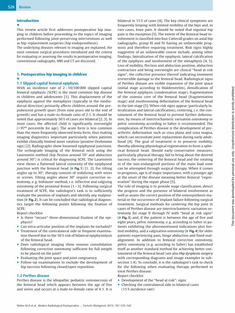
Fig. 2 9-year-old female patient with slipped capi-tal femoral epiphysis on the right side and presen-tation in house seven months after treatment exdomo. Initial imaging ex domo shows epiphysiolysison the right side a, which was stabilized using threeK-wires that were introduced through retrogradeinsertion b. Compared to screws, K-wires are atgreater risk of positional change (migration). Theenlarged picture detail shows that the medial andcaudal K-wire is projecting intraarticularly with itstip (c, black arrow). At time of presentation in housethere is already increasing joint space narrowing (d,black arrows) and persisting, motion-induced pain.Following implant removal, the subsequent MRI ex-amination shows depleted cartilage layer at the ac-etabulum roof, joint effusion and accompanyingbone marrow oedema corresponding to a severeosteoarthritis of the hip at infancy (e, coronal and f,transverse PD-w, fs). In addition, there is ossificationof the musculature on the left side at the formerentry point of the K-wires (arrow, status post im-plant removal one year after initial medical treat-ment) and also severe osteoarthritis of the right hip(g, arrow).
Table 1 In-house MRI protocol for congenital hip luxation in infants(3 Tesla).
sequence voxel size inmm measurement
time in s
remarks
coronal T2 TSE 0.6 × 0.6 × 2 90 BLADE
axial T2 TSE 0.6 × 0.6 × 2 80 BLADE
axial T2 TSE fs 0.6 × 0.6 × 2 75 BLADE
sagittal PD TSE 0.5 × 0.4 × 2 65 each side
coronal PD TSE 0.5 × 0.5 × 2 80
axial PD TSE 0.6 × 0.6 × 2 85
TSE: turbo spin-echo; PD: proton density; fs: fat-suppressed: sequence technique forreducing movement artifacts (also PROPELLER technique).
Weber M-A et al. Modern Radiological Postoperative… Fortschr Röntgenstr 2015; 187: 525–542
Review528
Thi
s do
cum
ent w
as d
ownl
oade
d fo
r pe
rson
al u
se o
nly.
Una
utho
rized
dis
trib
utio
n is
str
ictly
pro
hibi
ted.
teotomy differs primarily in that an aspherical osteotomy isperformed, both techniques follow the same principles. Inolder patients with hip dysplasia, a periacetabular osteot-omy (e. g. triple osteotomy) can be performed. This servesto reorient the acetabulum and normalize the deficientroofing, yet can be performed only on matured skeletons.With hip dysplasia, the labrum is typically hypertrophicand, in some cases, exhibits cystic changes with paralabralganglion cysts. These findings are typically located in theanterior-superior quadrant [8]. The damage pattern is sim-ilar to that of femoroacetabular CAM impingement or otherpathologies around the femoral head such as Perthes dis-ease and SCFE. Triple osteotomy involves performing an os-teotomy of the ischium, pubic bone and iliac bone and thenrotating and stabilizing the mobilized acetabulum with K-wires to create optimal roofing in the hip joint. Indicationsfor this surgery are hip dysplasia and persistent ossificationdefect in children and adults [3]. The goal of triple osteo-tomy is to pivot the socket above the femoral head and toachieve optimized roofing so that the forces in the joint aretransmitted over a larger surface, thus decreasing the pre-arthritic deformity (●" Fig. 6g).Following surgical treatment of hip dysplasia, the radiologist'srole is to evaluate the consolidation of the osteotomy spaces(●" Fig. 6 h, i) and the position of the material (●" Fig. 6j, k) (e. g.:
Is the Y-shaped growth plate injured with epiphysiodesis? Is for-eign material present in the joint space?). In summary, the pri-mary complications following surgical treatment of hip dyspla-sia are osteonecrosis of the femoral head, implant failure,development of pseudoarthrosis, i. e. absence of bone healingfor more than six months, as well as the recurrence of malposi-tion. Concerning pseudoarthrosis following triple osteotomy, itmust be noted that this condition is frequently asymptomatic atthe pubis and ischium.
2. Imaging following joint-preserving interventionsand joint-replacement surgery
2.1 Radiological evaluation after drilling intoosteonecrosis of the femoral headWhen evaluating the course of osteonecrosis of the femoralhead, is important that the correct stage is identified bothbefore and after therapy. The MRI classification accordingto ARCO (Association Research Circulation Osseous) is as fol-lows: In stage 0 all imaging techniques yield normal find-ings; in stage I signal changes are present in the necroticsegment; in stage II signs of T1-weighted hypointense de-marcation margin and the double-line sign in T2-weightingwith demarcation of the circumscribed osteonecrosis areawith intact femoral head contour; in stage III subchondral
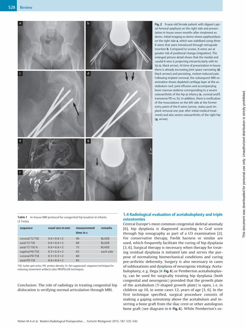
Fig. 3 7-year-old male patient with Perthes' disease. This case shows theosteonecrosis of the epiphysis more pronounced on the right than on theleft side using MRI (a, coronal T1w, white arrow) and using X-rays b. Surgicaltreatment with varisating osteotomy c was performed after the patient in-itially presented. The goal was to improve the contact between the femoral
head and the acetabular socket (containment). The following X-ray imagesdocument the follow-up over two years with increasing osseous consolida-tion of the osteotomy and reconstruction of the capital femoral epiphysisd–f.
Weber M-A et al. Modern Radiological Postoperative… Fortschr Röntgenstr 2015; 187: 525–542
Review 529
Thi
s do
cum
ent w
as d
ownl
oade
d fo
r pe
rson
al u
se o
nly.
Una
utho
rized
dis
trib
utio
n is
str
ictly
pro
hibi
ted.
fracture ("crescent sign"); and in stage IV secondary os-teoarthrosis with mechanical failure of the femoral head[5, 9]. In early stages of osteonecrosis of the femoral head,the necrotic lesion can be drilled (“core decompression” or
medullary decompression,●" Fig. 7) [10, 11]. The rational forthis is reducing the intraosseous pressure in the necrosiszone to thereby lower venous intraosseous hypertension.In addition, vascularization and bone growth stimulation
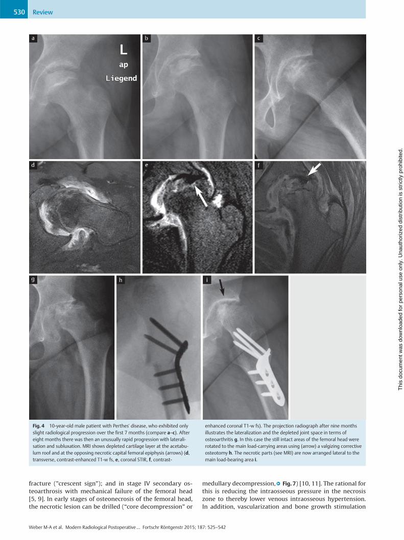
Fig. 4 10-year-old male patient with Perthes' disease, who exhibited onlyslight radiological progression over the first 7 months (compare a–c). Aftereight months there was then an unusually rapid progression with laterali-sation and subluxation. MRI shows depleted cartilage layer at the acetabu-lum roof and at the opposing necrotic capital femoral epiphysis (arrows) (d,transverse, contrast-enhanced T1-w fs, e, coronal STIR, f, contrast-
enhanced coronal T1-w fs). The projection radiograph after nine monthsillustrates the lateralization and the depleted joint space in terms ofosteoarthritis g. In this case the still intact areas of the femoral head wererotated to the main load-carrying areas using (arrow) a valgizing correctiveosteotomy h. The necrotic parts (see MRI) are now arranged lateral to themain load-bearing area i.
Weber M-A et al. Modern Radiological Postoperative… Fortschr Röntgenstr 2015; 187: 525–542
Review530
Thi
s do
cum
ent w
as d
ownl
oade
d fo
r pe
rson
al u
se o
nly.
Una
utho
rized
dis
trib
utio
n is
str
ictly
pro
hibi
ted.

using pluripotent stem cells from blood should be per-formed to avert a subchondral collapse, i. e. progressinginto ARCO stage III [11, 12]. The drilling should thus be per-formed in ARCO stages I and II. The 15-year success rates arereported to be 90% and 66% when performed in ARCOstages I and II, respectively [11, 12].The pronounced bone marrow edema without necroticzone (transient bone marrow edema syndrome, formerly:transient osteoporosis) is no longer seen as a preliminarystage of osteonecrosis, but rather as an independent pathol-ogy of still unclear pathophysiology and self-limitingcourse, which can, as so-calledmigrating bonemarrow ede-ma syndrome, affect other bones of the joint [10, 13, 14].Conclusion: The role of radiology following “core decom-pression” is to check the progress of the necrosis and moni-tor the success of therapy through MRI.
2.2 Radiological diagnostics following therapyfor femoroacetabular impingement (FAI)FAI is a frequent cause of early osteoarthrosis of the hip[15–17]. It affects 15% of the young population [8]. Forevaluating the severity of the disease, it is important tobear in mind that the labral lesion, which is frequently theprimary finding imaged, is only the tip of the iceberg. Pa-thology of the acetabulum and/or the femur usually in-volves cartilage damage [8]. A positive anterior labrum im-pingement test, i. e. a reproducible inguinal pain occurringwhen hip flection and inner rotation are combined, is a clin-ical sign of a labral lesion [10, 15, 16]. The diagnostic algo-rithm is comprised of medical history, clinical examination(positive inguinal tenderness, anterior labrum impinge-ment test), radiographs and subsequent MRI by means ofdirect MR arthrography for evaluating the labrum and car-
Fig. 5 Congenital hip luxation of an infant, confirmed through sonogram.MRI performed following repositioning showed normal articulation of thejoints (arrows) on the T2-w turbo spin-echo sequences (a, transverse and b,coronal). In contrast to this, are images c-g taken from an infant followingunsuccessful repositioning and bilateral persisting dorsally luxated femoral
heads (white arrows) and empty acetabulum (c, transverse T2 fs, sagittalproton-density weighting of the right d and left e hip joint). Five monthslater and after repeated attempts of repositioning of the right side, therewas joint effusion when compared to the left side and a pathological frac-ture (f, g, transverse T2-w fs in each case).
Weber M-A et al. Modern Radiological Postoperative… Fortschr Röntgenstr 2015; 187: 525–542
Review 531
Thi
s do
cum
ent w
as d
ownl
oade
d fo
r pe
rson
al u
se o
nly.
Una
utho
rized
dis
trib
utio
n is
str
ictly
pro
hibi
ted.

tilage [8, 17]. FAI is caused by incomplete congruence bet-ween the femoral head and the acetabulum. In the hip, dis-tinction is made between Pincer impingement and CAM
impingement [16, 17], with 86% of patients having mixedforms. A definitive diagnosis should be made only on thebasis of combined appropriate clinical and imaging evi-
Fig. 6 7-year-old boy with infantile cerebral palsy, spastic tetraparesis andneurogenic hip luxation on both sides. The radiographic Rippstein-1 view(X-ray survey in 90° flexion of knee/hip and 20° abduction of the hip) showsbilaterally distinct deficient roofing with subluxation of the femoral head onthe right side and bilateral fleeing and steep acetabulum roof e. Correctivesurgery with reconstruction of both hips was performed including varisa-tion osteotomy with derotation and acetabular roof reconstruction accord-ing to Dega. Dega acetabuloplasty a is in house the standard of treatmentand is performed as supraacetabular transiliac continuous osteotomy. In-traoperative X-rays show the curved bit, which is inserted until the Y-
shaped jointing b, the spreading of the osteotomy using a spreader c andthen the impact driving of the wedge of bone that has been removed fromthe proximal femur into the pelvic osteotomy. The wedge of bone getspressfit jammed and the image intensifier control image shows the final si-tuation after removal of the spreader d. Because patients with hip dysplasiapresent with a valgus and malpositioning in internal rotation e, treatment isvarisating and derotating f. Schematic drawing of triple pelvic osteotomy g.Bony non-union within the os ilium after triple pelvic osteotomy h, i andintraarticular position of material as complication of this operation j, k.
Weber M-A et al. Modern Radiological Postoperative… Fortschr Röntgenstr 2015; 187: 525–542
Review532
Thi
s do
cum
ent w
as d
ownl
oade
d fo
r pe
rson
al u
se o
nly.
Una
utho
rized
dis
trib
utio
n is
str
ictly
pro
hibi
ted.
dence [15, 17]. Only the correct roofing of the sphericalhead in a normal hip joint facilitates a physiological rangeof motion. With Pincer impingement, the excessive roofingresults in premature boney contact between joint compo-nents with limited range of motion. This in turn results indamage to the labrum and joint cartilage [15]. With CAMimpingement, it is the aspherical head that causes the lim-ited range of motion and joint damage [16]. The caused is areduced to absent offset between the femoral neck andhead, a change which is referred to as “bump deformity”.The term “bump” denotes the appositional boney changefrom which the name “cam” is derived [15, 17]. The MR ar-thrography of the hip is the gold standard for detecting lab-ral tear or detachment [18] with clearly higher sensitivityand specificity compared to normal MRI, even at 3 Tesla[18–20]. With axial slicing according the femoral neck thealpha angle is additionally determined using the Nötzlimethod (corresponding to femoral neck offset). This param-eter measures the angle between point A at which the ra-dius exits the sphericity of the femoral head (in axial slicing)and point B at which the midline through the femoral neckintersects the femoral head diameter [21].With FAI, the goal of therapy is to surgically correct the in-dividual pathological anatomy such that future mechanicaldamage to the labrum and cartilage are prevented andthe impingement-free range of motion is significantly in-creased [8, 20]. One method would be open hip dislocationsurgery [22]. The advantage of this method is that it pro-vides an excellent intraoperative overview of the femoralhead and acetabulum, allowing FAI pathologies to be visual-ized and treated laterally and dorsolaterally owing to the360° joint exposure. Complications are hemorrhage, infec-tion, overcorrection, risk of creating a bony predeterminedbreaking point and joint capsule adhesion. Another disad-vantage of open hip dislocation surgery is the risk of pseu-doarthrosis of the necessary trochanter osteotomy due tothe constant muscular tension on the major trochanter bythe gluteus medius and minimus muscles [8, 22]. A moreminimally invasive alternative is hip arthroscopy (hip ASC)for treating localized pathologies, particularly at the ante-rior-superior head-neck junction [8, 23]. The advantages of
this method are that it protects soft tissue and requires sig-nificantly shorter rehabilitation. Therapeutic labral resec-tion, reduction or short-distance refixation are also possiblewith this method. Complications of hip ASC are likewise de-velopment of joint capsule adhesion, in particular, however,a transient but persistent anesthesia in the thigh in the in-nervation region of the pudendal nerve. In addition, there isa slight risk of traction damage at the sciatic nerve, since ar-throscopy requires pronounced hip extension to allow in-struments access to the joint space. The disadvantages ofhip arthroscopy are reduced intraoperative visibility anddecreased verifiability of correct resection [8, 24]. The radi-ologist thus has the important task of verifying post-arthro-scopic success [20]. Pathological morphologies are arthros-copically trimmed back using shavers and spherical burrs(●" Fig. 8). Extensive or complete labral resection providespoorer clinical results than labral refixation. The goal isthus to reconstruct, and in the case of detachment, securethe labrum, e. g. through the implantation of anchors [8]. Inthis case, the radiologist must check that the anchors areproperly positioned post-surgery. New or persistent labrallesions can also be successfully imaged and evaluated post-surgery in MR arthrography and radial sequences [8].Post-surgical evaluation following treatment of FAI and lab-ral pathologies is based on the following points, and theradiologist should address the following questions in his orher report [20]:Report checklist
▶ Was the offset of the head-neck junction sufficiently re-stored?
▶ Was a “bump” overlooked, i. e., is there residual aspheri-city, e. g., dorsal or medial?
▶ Is there progress in cartilage damage over time?
▶ Are the anchors positioned correctly following labral re-fixation?
▶ Are there residual loose bodies present following arthro-scopy?
▶ Has new labral damage appeared?
▶ Can a temporary instability or predetermined breakingpoint in the femoral neck be assumed due to an overcor-rection?
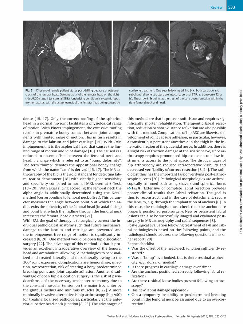
Fig. 7 17-year-old female patient status post drilling because of osteone-crosis of the femoral head. Osteonecrosis of the femoral head on the rightside ARCO stage II (a, coronal STIR). Underlying condition is systemic lupuserythematosus, with the osteonecrosis of the femoral head being caused by
cortisone treatment. One year following drilling b, c, both cartilage andsubchondral bone structure are intact (b, coronal STIR, c, transverse T2-wfs). The arrow in b points at the tract of the core decompression within theright femoral neck and head.
Weber M-A et al. Modern Radiological Postoperative… Fortschr Röntgenstr 2015; 187: 525–542
Review 533
Thi
s do
cum
ent w
as d
ownl
oade
d fo
r pe
rson
al u
se o
nly.
Una
utho
rized
dis
trib
utio
n is
str
ictly
pro
hibi
ted.
2.3 Imaging following hip endoprosthesisThere has been steady increase in the number of joint repla-cement surgeries in the hip and knee joints as well as theshoulders [25, 26]. In Germany more than 300000 joint re-placement surgeries are now performed annually, with158000 artificial hip implantations being performed in2008 [26]. Interestingly, there are no hard indications forhip endoprosthetic surgery [27]. In addition to frequent os-teoarthritis (degenerative, post-traumatic and dysplastic),osteonecrosis of the femoral head and femoral neck fractureare typical indications for a total endoprosthesis (TEP) of thehip.Not only radiological changes, but also movement re-strictions and limitations in everyday life accompanied by
duration and intensity of hip pain are important factorswhen determining whether this therapy is indicated [27].Hip endoprostheses can be divided into hemiprostheses(replacement of the femoral head and femoral neck, e. g.duo-head prosthesis) and total endoprostheses with repla-cement of acetabulum, femoral head and femoral neck ac-cording to the degree of replacement [28, 29]. Superficialreplacement involving replacement of the acetabular andfemoral head surfaces must also be mentioned. However,this solution is associated with poorer long-term resultsand is thus of subordinate clinical relevance. Furthermore,hip prostheses are commonly subdivided according to im-plantation technique into cemented hip TEP, especially in
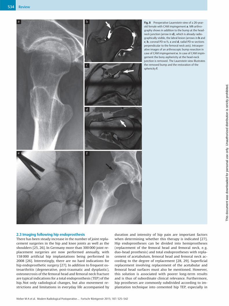
Fig. 8 Preoperative Lauenstein view of a 26-year-old female with CAM impingement a. MR-arthro-graphy shows in addition to the bump at the head-neck junction (arrow in d), which is already radio-graphically visible, the labral lesion (arrows in b andc; b, coronal PD-w fs, c and d, radial PD-w sectionsperpendicular to the femoral neck axis). Intraoper-ative images of an arthroscopic bump resection incase of CAM impingement e. In case of CAM impin-gement the bony asphericity at the head-neckjunction is removed. The Lauenstein view illustratesthe removed bump and the restoration of thesphericity f.
Weber M-A et al. Modern Radiological Postoperative… Fortschr Röntgenstr 2015; 187: 525–542
Review534
Thi
s do
cum
ent w
as d
ownl
oade
d fo
r pe
rson
al u
se o
nly.
Una
utho
rized
dis
trib
utio
n is
str
ictly
pro
hibi
ted.
osteopenic bones and older patients, and non-cementedhip TEPs. The later solutions are implanted primarily inyounger, active patients, since they can be replaced withless loss in bone mass [28, 29]. Special forms include tumorprostheses and revision prostheses, the modularity ofwhich allows them to adapt individually to the bone defectsin the femur and pelvis [28].When it came to long-term results, cemented prostheseswere the long-reigning gold standard, showing very posi-tive results especially in nation-wide registers for the Scan-dinavian countries [30]. Cement-free prosthetic systemshave been steadily approaching the long-term results oftheir cemented counterparts and have become increasinglypopular around the world because of the advantages theyoffer with regard to implantation and replacement [11,29]. Today, cement-free and cemented prostheses havecomparable service lives. International comparison hasshown clear differences in the use of these two anchoringsystems. In no way should cemented prostheses be labeledas “old” and cement-free as “modern”. The choice betweencemented and cement-free treatment is made on the basisof age, bone quality, concomitant diseases, previous sur-gery, etc. [28, 31, 32]. For cement-free systems, the pelvicbones and femur are prepared with surgical burrs andbone rasps, and the implant is inserted using the press-fittechnique (i. e. adjusting the pressure of the implant goinginto the bone without using external materials). High pri-mary stability is the prerequisite for secondary biologicalanchoring in the bone (osteointegration) [11]. Serving assockets are widely distributed hemispherical and roughsurfaced systems which are anchored in the acetabulumthrough press-fit with or without additional screws. Threa-ded cups are also still commonly used. For cement-freeshafts, proven systems with meta-diaphyseal anchoringare available that can be described as long-shaft systems.The short-shaft prostheses are based on a purely metaphy-seal anchoring, and the surgical technique demands preser-ving the medial femoral neck. In the case of standard inter-ventions, immediate mechanical loading is permitted forboth cement-free and cemented prostheses [33].In terms of tribological pairing, hip total endoprosthesis canbe divided into ceramic, metal and polyethylene sockets,which can in turn be combinedwith ceramic or metal heads(●" Fig. 9a–e). The goal is optimal tribological pairing of thehead and socket to keep the constantly present wear to anabsolute minimum [11]. The softer material always wearsoff. In the case of polyethylene-metal pairing, the biological-ly active polyethylene exhibits an average annual wear of0.2mm. The wear products activate osteoclasts via complexcascades and result in sometimes pronounced bone defectsaround the embedded prosthesis [29]. Metal prostheses en-tail the problem of metal particles resulting from wear.These particles can lead to elevated metal ion values on thesystemic level and be accompanied by the development oflocalized pseudotumors (see also subsection “Pseudotu-mors" further below) [11, 34, 36]. Ceramic-ceramic tribolo-gical pairings involve no appreciable wear, thus makingthese the preferred pairings for younger patients [11]. How-ever, ceramic-ceramic pairings do entail the risk of inlaybreakage [29], resulting in their having in some cases higherrevision rates than the pairing consisting of a ceramic headand highly cross-linked polyethylene inlay. During immedi-
ate postoperative evaluation, the radiologist's job is to de-tect or exclude peri- and postoperative complications suchas fracture, malposition and prosthesis luxation [11, 36]. Acorrectly positioned prosthesis will have a socket inclina-tion angle between 35° and 45° and anteversion between10° and 15° [11]. The inclination angle is measured at aline between the Kohler’s teardrops and the socket entranceplane [11, 37]. Socket anteversion is defined through theangle between the socket entrance plane (i. e. of the tangentat the anterior and posterior edge of the socket on CT slices)and the sagittal body axis (e. g. of the parallel lines to ananterior-posterior oriented line running precisely betweenthe two iliac crests) [11, 38]. Various techniques (Lewinnek,Widmer, Law or Pradhan) can be used for indirectly esti-mating anteversion through the ellipsoid representation ofthe socket [39]. In postoperative imaging, it is necessary todistinguish fractures from osteotomies (e. g. shortening os-teotomies on the femur). The radiologist should also indi-cate whether the components are over- or undersized. Thisis visible, for one, in the correct restoration of patient-specific biomechanical conditions with femoral offset andleg length. With cement-free shafts, the implant size is cor-rect if there is sufficient cortical bone contact. The post-operative radiolucent margin is a periprosthetic brightarea visible in non-contrast radiographs which resultsfrom a disparity between the surgically milled bone andprosthesis position. With the osseointegration of the ce-ment-free prosthesis, this margin usually decreases signifi-cantly over time [28].Over the long term, the following complications can arisewith hip endoprostheses: inlay wear or failure (●" Fig. 9f–j),septic or aseptic loosening (●" Fig. 10), as well as infections[25, 29, 40] and the sinking of the prosthetic shaft into thefemur (“subsiding”) [41]. Careful evaluation of the head po-sition over a series of radiographs can prevent the need forsocket replacement in the event of inlay failure. Radiologi-cal follow-up with conventional radiographs (low pelvicoverview and axial view of hip) every two years is thereforeadvised. Other problems are heterotopic ossification (para-articular ossification, PAO) or pseudotumors as well as weargranulomas. The key to diagnosing loosening is the appear-ance of a radiolucent margin of over two millimeters pro-gressing over time as well as the migration of the prosthe-sis, e. g. the sinking of the shaft or the protrusion of thesocket [11, 28, 40]. The appearance of a radiolucent marginonly in the proximal femoral area of the prosthesis (in theintertrochanteric region) initially has no clinical relevanceand physiologically results from mechanical loading andload effect further distal [28]. With cemented systems, theappearance of a radiolucent margin especially at the an-choring point is clinically relevant. Supplemental scintigra-phy can be performed when radiographs as primary ima-ging modality and CT, which is the most sensitive atdetecting the appearance of radiolucent margins, are notsufficiently conclusive [28]. The diagnostic value of thesemodalities, however, is undisputed, particularly in the firstone or two years following implantation. Implant migrationor positional change as well as breakage of components orthe surrounding cement are other sensitive parameters fordiagnosing a loosening. [29]. Thorough evaluation shouldtherefore always include comparison with previous images[11]. Periprosthetic fractures (●" Fig. 11a–d) may occur in-
Weber M-A et al. Modern Radiological Postoperative… Fortschr Röntgenstr 2015; 187: 525–542
Review 535
Thi
s do
cum
ent w
as d
ownl
oade
d fo
r pe
rson
al u
se o
nly.
Una
utho
rized
dis
trib
utio
n is
str
ictly
pro
hibi
ted.
traoperatively, following surgery during mobilization andas a result of trauma. Avulsion fractures are frequently ob-served on the greater trochanter, the same being true of ob-lique or spiral fractures on the femoral shaft. Acetabularfractures around the implanted cup occur more rarely.When planning therapy, diagnosing or excluding a loosen-ing of the prosthesis is crucial. A loose prosthesis must bereplaced. In cases of doubt, supplemental CT should be per-formed liberally [40]. Periprosthetic fractures detected in-traoperatively through fluoroscopic examination are treat-ed immediately by means of cerclage.
InfectionsProsthesis-related infection is a formidable complication,appearing in 0.5–1.0% of patients worldwide. The risk fac-tors are advanced age, obesity, diabetes mellitus and im-mune suppression. Distinction is made between early infec-tions, occurring within six weeks post surgery, and lateinfections [28, 42]. Early infections can be treated throughattempted preservation of the prosthesis by means of deb-ridement and purging. Late infections necessitate a single oreven double implant replacement. The radiologist needs toindicate whether the infection process has made contactwith the prosthesis (●" Fig. 11e–f) or whether a periosteal re-action or osteolysis with blurry edges is present [11, 29, 40].Inversion recovery sequences such as STIR are better suited
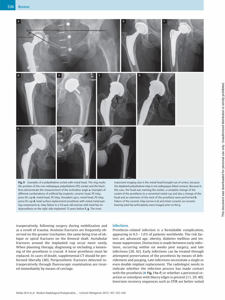
Fig. 9 Examples of a polyethylene socket with metal head. The ring marksthe position of the non-radiopaque polyethylene (PE) socket and the blacklines demonstrate the measurement of the inclination angle a. Examples ofdifferent combinations of artificial hip implants: ceramic head, PE inlay,press-fit cup b, metal head, PE inlay, threaded cup c, metal head, PE inlay,press-fit cup d, total surface replacement prosthesis with metal-metal pair-ing components e. Inlay failure in a 54-year-old woman with total hip en-doprosthesis on the right side implanted 15 years before f, g. The most
important imaging clue is the metal head brought out of centre, becausethe depleted polyethylene inlay is not radiopaque (black arrows). Because inthis case, the head was reaming the socket, a complete change of thesocket of the prosthesis to a cemented metal cup and also a change of thehead and an extension of the neck of the prosthesis were performed h.Failure of the ceramic inlay (arrow in i) and intact ceramic-on-ceramicbearing total hip arthroplasty were imaged prior to this j.
Weber M-A et al. Modern Radiological Postoperative… Fortschr Röntgenstr 2015; 187: 525–542
Review536
Thi
s do
cum
ent w
as d
ownl
oade
d fo
r pe
rson
al u
se o
nly.
Una
utho
rized
dis
trib
utio
n is
str
ictly
pro
hibi
ted.
than spectral fat saturation, while T1- and T2-weighted(turbo-) spin echo sequences are better suited than gradientecho sequences at decreasing the metal artifacts of the hipendoprosthesis and detecting periprosthetic bone and softtissue changes as well as fluid collections [36, 42, 43]. Theabsence of joint effusion has a high negative predictive val-ue for an infection of 96% [36]. Because of the applicabilityof MRI, nuclear medicine methods such as scintigraphy or
positron emission tomography (PET) are used less frequent-ly for these clinical problems [28].
PseudotumorsPseudotumors appearing with polyethylene inlay are calledabrasion granulomas (●" Fig. 12a–c). The abrasion debris ofthe polyethylene inlay is engulfed by macrophages, whichaccumulate in foreign body granulomas and usually have adensity of 30 Houndsfield units in CT. In MRI they appear
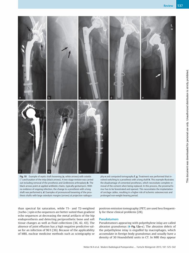
Fig. 10 Example of septic shaft loosening (a, white arrows) with osteitis(*) and luxation of the inlay (black arrows). A two-stage revision was carriedout including removal of the prosthesis and Girdlestone arthroplasty b. Theblack arrows point at applied antibiotic chains, typically gentamycin. Withno evidence of ongoing infection, the change to a prosthesis with a longshaft was performed c, d. Examples of pronounced loosening of the pros-thesis shafts with large osteolysis margins (arrows) at projection radiogra-
phy e and computed tomography f, g. Treatment was performed that in-volved switching to a prosthesis with a long shaft h. This example illustratesthe disadvantage of cemented prostheses, which necessitate complete re-moval of the cement when being replaced. In this process, the proximal fe-mur has to be fenestrated and opened. This necessitates the implantationof cerclage cables, resulting in a higher risk of ischemic osteonecrosis andprolonged non-weight-bearing period.
Weber M-A et al. Modern Radiological Postoperative… Fortschr Röntgenstr 2015; 187: 525–542
Review 537
Thi
s do
cum
ent w
as d
ownl
oade
d fo
r pe
rson
al u
se o
nly.
Una
utho
rized
dis
trib
utio
n is
str
ictly
pro
hibi
ted.
hypointense and slightly hyperintense in relation to themuscle in T1- and T2-weighted sequences, respectively,with T2-weighting showing a hypointense line to the bonemarrow, and typically involve no perifocal bone marrowedema [36, 40, 42]. With metal-metal tribological pairings,the terms cyst, ALVAL (aseptic lymphocytic vasculitis-asso-ciated lesion) or ARMD (adverse reactions to metal debris)are used synonymously with pseudotumor. These casesusually involve elevated metal ions in serum [11, 35]. Thepatients are usually below the age of 50 and have under-
gone joint replacement surgery with metal-metal tribologi-cal paring (e. g. surface replacement) [34]. The incidencerate is 1–4% with a peak appearing four to five years fol-lowing TEP implantation. Pseudotumors frequently expandinto the iliopsoas muscle [11, 34]. The key to diagnosis is de-tecting a space occupation in connection with the hip jointof the prosthesis and, in the case of metal-metal pairings,solid components and/or a low-signal wall in T2-weighting(●" Fig. 12d–j) [42, 43]. Multiple grading systems for soft tis-sue changes occurring with metal-metal prostheses have
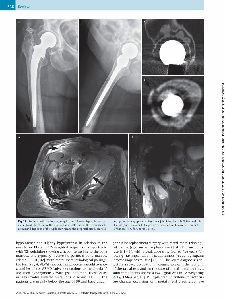
Fig. 11 Periprosthetic fracture as complication following hip endoprosth-esis a, b with break-out of the shaft at the middle third of the femur (blackarrow) and depiction of the cup loosening and the periprosthetic fracture at
computed tomography c, d. Prosthetic joint infection at MRI, the fluid col-lection (arrows) contacts the prosthesis material (e, transverse, contrast-enhanced T1-w fs, f, coronal STIR).
Weber M-A et al. Modern Radiological Postoperative… Fortschr Röntgenstr 2015; 187: 525–542
Review538
Thi
s do
cum
ent w
as d
ownl
oade
d fo
r pe
rson
al u
se o
nly.
Una
utho
rized
dis
trib
utio
n is
str
ictly
pro
hibi
ted.
been proposed. According to Hauptfleisch, pseudotumorsappearing with metal-metal pairings can be categorizedinto three types [34]:
▶ Type 1: cystic, wall ≤ 3mm, usually minor symptoms
▶ Type 2: cystic, wall > 3mm
▶ Type 3: primarily solid with the highest revision rateIt is the consistency of the pseudotumor rather than its sizealone that determine the signs and symptoms [34].
LuxationsRecurring luxation of hip TEP (●" Fig. 12k, l) is a complicationthat has decreased in incidence since the introduction of
prosthesis planning involving restoration of the patient-specific anatomy. It can be caused by incorrect cup position(excessively high inclination angle, incorrect version (withcorrespondingly different frequency depending on surgicalaccess pathway used)) as well as incorrect shaft position(excessive/insufficient antetorsion) [29]. Besides eliminat-ing the cause, recurring luxation following hip total endo-prosthesis can be treated by lengthening the prosthesisneck to create more tension on the soft tissues or using aninlay with a cambered cup rim [33]. Enlarging the diameterof the prosthetic head increases the degree of the freedomof motion of the prosthesis to the effect that the prosthesis
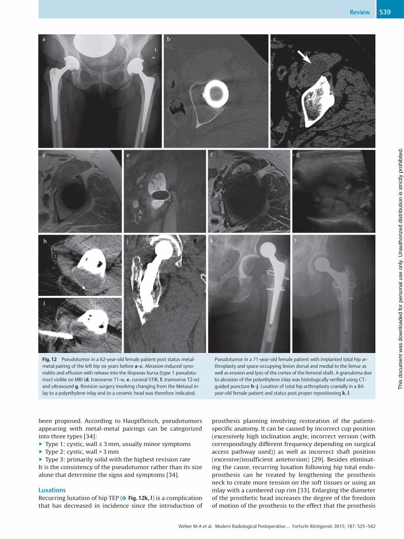
Fig. 12 Pseudotumor in a 62-year-old female patient post status metal-metal pairing of the left hip six years before a–c. Abrasion-induced syno-vialitis and effusion with release into the iliopsoas bursa (type 1 pseudotu-mor) visible on MRI (d, transverse T1-w, e, coronal STIR, f, transverse T2-w)and ultrasound g. Revision surgery involving changing from the Metasul in-lay to a polyethylene inlay and to a ceramic head was therefore indicated.
Pseudotumor in a 71-year-old female patient with implanted total hip ar-throplasty and space-occupying lesion dorsal and medial to the femur aswell as erosion and lysis of the cortex of the femoral shaft. A granuloma dueto abrasion of the polyethylene inlay was histologically verified using CT-guided puncture h–j. Luxation of total hip arthroplasty cranially in a 84-year-old female patient and status post proper repositioning k, l.
Weber M-A et al. Modern Radiological Postoperative… Fortschr Röntgenstr 2015; 187: 525–542
Review 539
Thi
s do
cum
ent w
as d
ownl
oade
d fo
r pe
rson
al u
se o
nly.
Una
utho
rized
dis
trib
utio
n is
str
ictly
pro
hibi
ted.
neck does not strike against the rim of the cup (impinge-ment) and thereby damage the cup or lever the prosthesishead out of the cup (luxation, subluxation) [29, 33]. The lar-ger the prosthesis head, the lower the risk of luxation.
Heterotopic ossifications (PAO)While the rate of incidence of heterotopic ossifications isvery high especially over the long term at 40–50%, it is
asymptomatic in 70% of patients [11, 40]. Heterotopic ossifi-cations appear in the area of the former capsule and thepara-articular soft tissue. The risk of developing PAO is in-creased in patients with diffuse idiopathic skeletal hyperos-tosis (DISH), Parkinson’s disease, Paget’s disease, Bechterew’sdisease or a past history of PAO [11]. Muscle-preserving sur-gical techniques and prophylaxis with nonsteroidal anti-in-flammatory drugs can reduce the appearance of PAOs. Pro-
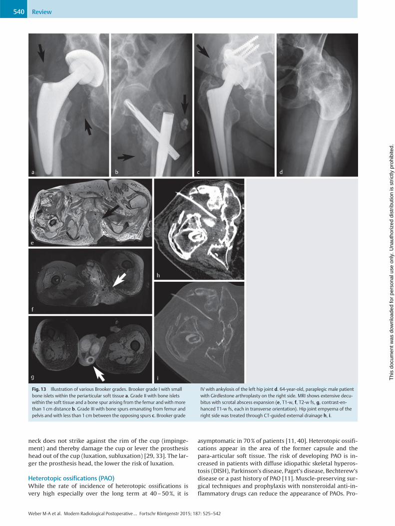
Fig. 13 Illustration of various Brooker grades. Brooker grade I with smallbone islets within the periarticular soft tissue a. Grade II with bone isletswithin the soft tissue and a bone spur arising from the femur and with morethan 1 cm distance b. Grade III with bone spurs emanating from femur andpelvis and with less than 1 cm between the opposing spurs c. Brooker grade
IV with ankylosis of the left hip joint d. 64-year-old, paraplegic male patientwith Girdlestone arthroplasty on the right side. MRI shows extensive decu-bitus with scrotal abscess expansion (e, T1-w, f, T2-w fs, g, contrast-en-hanced T1-w fs, each in transverse orientation). Hip joint empyema of theright side was treated through CT-guided external drainage h, i.
Weber M-A et al. Modern Radiological Postoperative… Fortschr Röntgenstr 2015; 187: 525–542
Review540
Thi
s do
cum
ent w
as d
ownl
oade
d fo
r pe
rson
al u
se o
nly.
Una
utho
rized
dis
trib
utio
n is
str
ictly
pro
hibi
ted.
nounced PAOs following primary implantations have thusbecome less common. According to Brooker, heterotopic os-sification in the hip is categorized into four grades (●" Fig. 13)[44]:
▶ Grade I – bone islets in soft tissue
▶ Grade II – osteophytes emanating from the femur or pel-vis
▶ Grade III – same as grade II but with bone spurs beingspaced less than 1 cm apart
▶ Grade IV – complete boney ankyloses.
Metal artefacts in cross-sectional imagingIn MRI, signal dropouts and noise at the phase interfaces ofprimarily magnetic materials (e. g. metal) are referred to assusceptibility artefacts. While in principle these can appearwith any pulse sequence, spin echo sequences are less sen-sitive in this area owing to their pulse characteristics. Inroutine diagnostic testing, artifacts can be reduced throughthe following measures:
▶ Using spin echo and turbo spin echo sequences instead ofgradient echo (GRE) sequences as well as using STIR se-quences instead of frequency-selective techniques for fatsuppression
▶ Interchanging phase and frequency direction
▶ Imaging with higher sensitivity bandwidth, if applicableorienting the longitudinal axis of the metal implant alongthe primary direction of the magnetic field
▶ Using modern artifact-reducing sequences, e. g. SEMAC(slice-encoding for metal artifact correction) or MARVRIC(multiple-acquisition variable-resonance imaging combi-nation; GE Healthcare, Milwaukee, WI) [40, 42].
CT involves primarily hardening artifacts along metallicnon-radiopaque materials. For iterative reconstructionthere are already commercially available algorithms forthese cases (e. g. O-MAR, Metal Artifact Reduction for Or-thopedic Implants) [45]. With this technique, the first, un-corrected image is reconstructed and regularized, beforethen being compared with the gathered raw data. As longas these fail to match, other reconstructions are generated,thus constituting what is referred to as filtered back-projec-tion. Image quality increases with the number of recon-structions. However, the disadvantage of this technique isthe increased radiation dose required. Even CT scanning it-self can considerably reduce artifacts through dual-energytechniques, allowing the same bodily region to be examinedat two different energy levels [40].
Summary and core statements on imaging after hip en-doprosthesisProblems occurring over the course of time with hip endo-prostheses must be addressed through imaging as de-scribed below. Projection radiography examinations consti-tute the basic diagnostic means for evaluating implantposition and detecting periprosthetic fractures, any loosen-ing or soft tissue ossification. Computed tomography is theprimary diagnostic method to enlist when radiographsyield unclear findings and periprosthetic fractures are sus-pected [29]. Modern prostheses such as those made of tita-nium alloys generate few artifacts. Sonography is suited fordetecting or excluding joint effusion or postoperative sero-ma, while allowing direct fluid puncture and draining [25,29]. MRI is indicated for suspected infection or tumor recur-
rence in the case of tumor prostheses and pseudotumors. Itis important that many clinical questions can be answeredthrough thorough evaluation of conventional radiographsover the course of time. In this process it is also imperativethat the entire prosthesis is imaged completely.
References01 Funk JF, Lebek S. Epiphyseolysis capitis femoris. Neue Aspekte in Diag-
nostik und Therapie. Orthopäde 2014; 43: 742–74902 Graf R. Radiologisch-orthopädische Anforderungsprofile bei der kin-
dlichen Hüftdysplasie, der Koxitis und der Epiphyseolysis capitis fe-moris. Radiologe 2002; 42: 467–473
03 Breusch S, Mau H, Sabo D et al. Untere Extremität. In: Breusch S,Clarius M, Mau H. et al. (eds). Klinikleitfaden Orthopädie Unfallchir-urgie. 7. Aufl. München: Elsevier; 2013: 429–562
04 Kramer J, Hofmann S, Scheurecker A et al. Morbus Perthes. Radiologe2002; 42: 432–439
05 von Stillfried E, Weber MA. Aseptische Osteonekrosen bei Kindern undJugendlichen. Orthopäde 2014; 43: 750–757
06 Multerer C, Döderlein L. Angeborene Hüftdysplasie und -luxation. Be-währte und neue Verfahren in Diagnostik und Therapie. Orthopäde2014; 43: 733–741
07 Gould SW, Grissom LE, Niedzielski A et al. Protocol for MRI of the hipsafter spica cast placement. J Pediatr Orthop 2012; 32: 504–509
08 Steppacher SD, Tannast M, Siebenrock KA. Labrumläsionen des Hüftge-lenks. Orthopädie und Unfallchirurgie up2date 2008; 3: 215–232
09 Kramer J, Scheurecker G, Scheurecker A et al. Hüftkopfnekrose. Radi-ologe 2009; 49: 410–418
10 Mattes T, Fraitzl C, Ostertag O et al. Differentialdiagnosen der asepti-schen Hüftkopfnekrose. Artikulärer Leistenschmerz des Erwachsenen.Orthopäde 2007; 36: 414–422
11 Carty FL, Cashman JP, Parvizi J et al. Imaging of the postoperative hip.Semin Musculoskelet Radiol 2011; 15: 357–371
12 Fairbank AC, Bhatia D, Jinnah RH et al. Long-term results of core de-compression for ischaemic necrosis of the femoral head. J Bone JointSurg Br 1995; 77: 42–49
13 Karantanas AH. Acute bone marrow edema of the hip: role of MR ima-ging. Eur Radiol 2007; 17: 2225–2236
14 Vande Berg BC, Lecouvet FE, Koutaissoff S et al. Bone marrow edema ofthe femoral head and transient osteoporosis of the hip. Eur J Radiol2008; 67: 68–77
15 Mamisch TC, Werlen S, Zilkens C et al. Radiologische Diagnose des fe-moroacetabularen Impingements. Radiologe 2009; 49: 425–433
16 Reid GD, Reid CG,Widmer N et al. Femoroacetabular impingement syn-drome: an underrecognized cause of hip pain and premature osteoar-thritis? J Rheumatol 2010; 37: 1395–1404
17 Räuchle M, Cemerka M, Eibenberger B et al. Arthrose – update 2012.Radiologe 2012; 52: 149–155
18 Czerny C,Oschatz E, Neuhold A et al.MR Arthrograpie des Hüftgelenkes.Radiologe 2002; 42: 451–456
19 Petersilge CA. MR arthrography for evaluation of the acetabular lab-rum. Skeletal Radiol 2001; 30: 423–430
20 Llopis E, Fernandez E, Cerezal L. MR and CT arthrography of the hip.Semin Musculoskelet Radiol 2012; 16: 42–56
21 Nötzli HP,Wyss TF, Stoecklin CH et al. The contour of the femoral head-neck junction as a predictor for the risk of anterior impingement. JBone Joint Surg Br 2002; 84: 556–560
22 Ganz R, Gill TJ, Gautier E et al. Surgical dislocation of the adult hip atechnique with full access to the femoral head and acetabulum with-out the risk of avascular necrosis. J Bone Joint Surg Br 2001; 83:1119–1124
23 Byrd JW. Hüftarthroskopie. Portaltechnik und arthroskopische Anato-mie. Orthopäde 2006; 35: 41–53
24 Botser IB, Smith TW Jr, Nasser R et al. Open surgical dislocation versusarthroscopy for femoroacetabular impingement: a comparison of clin-ical outcomes. Arthroscopy 2011; 27: 270–278
25 Barron D. CT and MRI of hip arthroplasty. Clin Radiol 2007; 62: 1172–1173
26 Pfeil J, Höhle P, Rehbein P. Bilateraler endoprothetischer Ersatz amHüft- oder Kniegelenk. Dtsch Arztebl Int 2011; 108: 463–468
27 Richter-Kuhlmann EA. Hochschulmedizin: Balanceakt Indikationsstel-lung. Dtsch Arztebl 2013; 110: B–749
Weber M-A et al. Modern Radiological Postoperative… Fortschr Röntgenstr 2015; 187: 525–542
Review 541
Thi
s do
cum
ent w
as d
ownl
oade
d fo
r pe
rson
al u
se o
nly.
Una
utho
rized
dis
trib
utio
n is
str
ictly
pro
hibi
ted.

28 Mayerhoefer ME, Fruhwald-Pallamar J, Czerny C. Bildgebung beiHüftgelenkendoprothesen. Radiologe 2009; 49: 419–424
29 Miller TT. Imaging of hip arthroplasty. Eur J Radiol 2012; 81: 3802–3812
30 Hailer NP, Garellick G, Kärrholm J. Uncemented and cemented primarytotal hip arthroplasty in the Swedish Hip Arthroplasty Register. ActaOrthop 2010; 81: 34–41
31 Azegami S, Gurusamy KS, Parker MJ. Cemented versus uncementedhemiarthroplasty for hip fractures: a systematic review of randomisedcontrolled trials. Hip Int 2011; 21: 509–517
32 Abdulkarim A, Ellanti P, Motterlini N et al. Cemented versus uncemen-ted fixation in total hip replacement: a systematic review and meta-a-nalysis of randomized controlled trials. Orthop Rev (Pavia) 2013; 5: e8.DOI: 10.4081/or.2013.e8
33 Duparc J. (ed). Chirurgische Techniken in Orthopädie und Traumatolo-gie. München: Urban & Fischer Verlag; 2005
34 Hauptfleisch J, Pandit H, Grammatopoulos G et al. AMRI classification ofperiprosthetic soft tissue masses (pseudotumours) associated withmetal-on-metal resurfacing hip arthroplasty. Skeletal Radiol 2012;41: 149–155
35 Parsons TM, Satchithananda K, Berber R et al. Magnetresonanztomo-graphische Untersuchungen bei Problemen mit Metall-auf-Metall-Im-plantaten. Orthopäde 2013; 42: 629–636
36 Cahir JG, Toms AP,Marshall TJ et al. CT andMRI of hip arthroplasty. ClinRadiol 2007; 62: 1163–1171
37 Jesse MK, Petersen B, Strickland C et al. Normal anatomy and imaging ofthe hip: emphasis on impingement assessment. Semin MusculoskeletRadiol 2013; 17: 229–247
38 Tschauner C, Fock CM,Hofmann S et al. Rotationsfehler des Hüftgelenks.Radiologe 2002; 42: 457–466
39 Pradhan R. Planar anteversion of the acetabular cup as determinedfrom plain anteroposterior radiographs. J Bone Joint Surg Br 1999;81: 431–435
40 Agten CA, Sutter R, Pfirrmann CWA. CT und MRT der Hüftprothese.Radiologe 2014; 54: 715–726
41 Hendrich C, Sauer U, Albrecht T et al. Subsidence of titanium straightstems in combination with highly viscous bone cement. Int Orthop2005; 29: 96–100
42 Hayter CL, Koff MF, Potter HG. Magnetic resonance imaging of the post-operative hip. J Magn Reson Imaging 2012; 35: 1013–1025
43 Ostlere S. How to image metal-on-metal prostheses and their compli-cations. Am J Roentgenol 2011; 197: 558–567
44 Brooker AF, Bowerman JW, Robinson RA et al. Ectopic ossification fol-lowing total hip replacement. Incidence and amethod of classification.J Bone Joint Surg Am 1973; 55: 1629–1632
45 Kidoh M, Nakaura T, Nakamura S et al. Reduction of dental metallic ar-tefacts in CT: value of a newly developed algorithm for metal artefactreduction (O-MAR). Clin Radiol 2014; 69: e11–e16
Weber M-A et al. Modern Radiological Postoperative… Fortschr Röntgenstr 2015; 187: 525–542
Review542
Thi
s do
cum
ent w
as d
ownl
oade
d fo
r pe
rson
al u
se o
nly.
Una
utho
rized
dis
trib
utio
n is
str
ictly
pro
hibi
ted.