models p204-4120/4121 · p204-4120 and p204-4121 spare parts list item part no. description qty. 1...
TRANSCRIPT
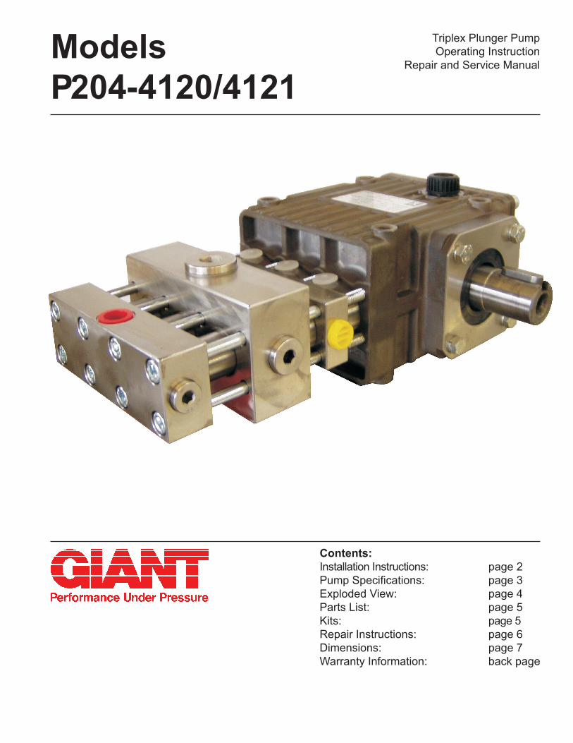
ModelsP204-4120/4121
Contents:Installation Instructions: page 2Pump Specifications: page 3Exploded View: page 4Parts List: page 5Kits: page 5Repair Instructions: page 6Dimensions: page 7Warranty Information: back page
Triplex Plunger PumpOperating Instruction
Repair and Service Manual
2
INSTALLATION INSTRUCTIONS Safety Rule: The pump is not to be used without a safety valve.
Operation and MaintenanceCheck oil level prior to starting and ensure trouble-free fluid supply.The viscosity and the vapor point of the conveyed medium determine the required input pressure.The valves of the pump open at a pressure of 5.8 PSI (0.4 bar). This resistance must also be considered when calculating the input pressure. The maximum input pressure is 145 PSI (10 bar).Oil: Use only 9.5 ounces (0.28 liters) of industrial gear oil SAE90 (Giant’s part number 01154) or as per ISO VG e.g. Aral Degol BG 150 before starting.Initial change after 50 operating hours and then every 500 operating hours or 1 year if used less.Caution when operating in damp places or with high temperature fluctuations. Oil must be changed imme-diately should condensate (frothy oil) occur in the gear box.
Safety RulesPump operation without safety valve as well as any excess in temperature or speed limits, automatically voids the warranty. The safety valve must be regulated in accordance with the guidelines for liquid spray-ing units so that the maximum admissible operating pressure can not be exceeded by more than 10%.
When the pump is in operation, the drive shaft end and the coupling must be covered up by either a con-tact-protector or by a coupling bell. Pressure in discharge line and in pump must be at zero before any maintenance to the pump takes place. Close up suction line. Disconnect fuses to ensure that the driving motor does not get switched on accidentally.Make sure that all parts on the pressure side of the unit are vented before starting the pump. In order to prevent air, or an air-water mixture being absorbed and to prevent cavitation occurring, the pump-NPSHR suction head and water temperature must be kept under control.
Cavitation and/or compression of gases lead to uncontrollable pressure-kicks which can ruin pump and unit parts and also be dangerous to the operator or anyone standing nearby.
Before pumping inflammable, explosive and toxic media - the pump manufacturer must under all circumstances be consulted with regard to the resistance of the pump material. It is the responsi-bility of the equipment manufacture and/or operator to ensure that all pertinent safety regulations are adhered to.
For additional information on how this pump functions, go to:https://www.giantpumps.com/wp-content/uploads/2019/06/P201_P202_P204_P213-Function-Description.pdf

3
P204-4120 and P204-4121 Pump Specifications
U.S. MetricVolume......................................................................1.8 GPM* ...............................6.8 L/min*Discharge Pressure ..................................................3200 PSI ................................220 BarPower Required ........................................................4.0 BHP ..................................3.0 kWCrankshaft Speed .....................................................................................................1450 RPMPlunger Diameter......................................................0.47” .......................................12 mmPlunger Stroke ..........................................................0.56” .......................................14.1 mmCrankshaft Diameter.................................................0.98” .......................................24 mmKey Width .................................................................0.31” .......................................8 mmCrankshaft Mounting ................................................................................................Either sideCrankshaft Rotation ......................................................................Top of Pulley Towards Fluid EndTemperature of Pumped Fluids ................................140 oF .....................................60 oCInlet Ports .................................................................................................................(2) 1/2” BSPDischarge Ports ........................................................................................................(2) 1/4” BSPWeight ......................................................................13.9 lbs. .................................6.3 kgCrankcase Oil Capacity ............................................9.5 Ounces. ............................0.28 Liters
* Theoretical displacement per revolution is approximately 0.161 ounce (4.75 cm3)
Important! The 1/8” rinsing connection on both sides serves to place a separating agent (e.g. DOP) behind the medium seal on the suction side. This stops leakage (e.g. with Iscocyanate) from crystallizing. When pumping different types of Freon, the pressure in the rinsing system should be approximately 7.25 PSI (0.5 bar) higher than on the suction side of the pumped medium.To vent the pump easily on the discharge side, it is recommeded to install a T-piece with a high-pressure cut-off tap as close as possible to the discharge port.
HORSEPOWER RATINGS:
The rating shown are the power require-ments for the pump. Gas engine power outputs must be approximately twice the pump power requirements shown above.
We recommend a 1.15 service factor be speci-fied when selecting an electric motor as the power source. To compute specific pump horse power requirements, use the following formula:
HP = (GPM X PSI) / 1450
P204-4120/P204-4121 Horsepower RequirementsRPM GPM 500 PSI 1000 PSI 2000 PSI 3200 PSI725 0.9 0.31 0.62 1.2 2.0900 1.1 0.38 0.76 1.5 2.4
1200 1.5 0.52 1.0 2.1 3.31450 1.8 0.62 1.2 2.5 4.0

4
Exploded View - P204-4120 and P204-4121

5
ITEM PART NO. DESCRIPTION QTY.23 07770-0001 O-Ring, Viton (P204-4121) 9 24 05859 Spacer Ring 325 05860 Support Ring 326 05861 Rod Seal (P204-4120) 326 05861-0010 Rod Seal (P204-4121) 327 05862 Guide Band 328 05863 Guide Sleeve 329 08416 O-Ring (P204-4120) 329 08416-0001 O-Ring (P204-4121) 330 05864 Rod Seal (P204-4120) 330 05864-0010 Rod Seal (P204-4121) 331 05865 Seal Retainer 332 05866 Inlet Casing 133 05867 Plug, 1/2” BSP 134 05868 Seal, 1/2” BSP 135 07423-0100 Plug, 1/4” BSP 236 05869 Seal, 1/4” BSP 237 05870 Valve Seat 338 05454 Valve Assembly 639 05871 O-Ring (P204-4120) 339 05871-0001 O-Ring (P204-4121) 340 12017 O-Ring (P204-4120) 340 11507-0001 O-Ring (P204-4121) 341 05872 Discharge Casing 142 05873 Hexagon Socket Screw 844 06589 Socket Plug, 1/8” BSP 145 05874 Seal, 1/8” BSP 1
P204-4120 and P204-4121 Spare Parts List
ITEM PART NO. DESCRIPTION QTY. 1 08300CA Crankcase, Anodized 12 08301 Oil Dipstick with O-Ring 13 08302A Crankcase Cover, Anodized 13A 07190 Drain Plug and Gasket 14 08005 O-Ring 15 08185 Oil Drain Plug with Gasket 16 07188 Screw, Short Cover 46A 07223-0100 Spring Washer 47 08303 Bearing Cover 28 08491 Sight Glass 19 07193 O-Ring for Sight Glass 110 07225 Screw with Lock Washer 811 08331 Radial Shaft Seal 112A 04917 Ball Bearing 112B 01086 Ball Bearing 113 04919 Crankshaft 114 06207 Fitting Key 115 08333 Connecting Rod 316 05453 Plunger 317 08442 Wrist Pin 319 08356-0010 Oil Seal 320 05855 Spacer ring 320A 05856 Plug 321 05857 Intermediate Casing 122 06717 Seal Ring, gray 322A 05858 Seal Ring, black 623 07770 O-Ring (P204-4120) 9
Seal Repair Kit - P204-4120 - #09711Item # Part # Description Qty.22 06717 Seal Ring, gray 322A 05858 Seal Ring, black 623 07770 O-Ring 926 05861 Rod Seal 3 27 05862 Guide Band 329 08416 O-Ring 330 05864 Rod Seal 339 05871 O-Ring 340 12017 O-Ring 3
Oil Seal Repair Kit - #09144-0010Item # Part # Description Qty.19 08356-0010 Oil Seal 3
P204-4120 and P204-4121 Repair Kits
Seal Repair Kit - P204-4121 - #09711-0021Item # Part # Description Qty.22 06717 Grooved Seal Ring 322A 05858 Grooved Ring 623 07770-0001 O-Ring, Viton 926 05861-0010 Rod Seal, Viton 3 27 05862 Guide Band 329 08416-0001 O-Ring, Viton 330 05864-0010 Rod Seal, Viton 339 05871-0001 O-Ring, Viton 340 11507-0001 O-Ring, Viton 3

6
P204-4020 and P204-4021 Repair InstructionsAdditional repair instructions shown on Giant’s website:(https://www.giantpumps.com/wp-content/uploads/2019/06/P202-P204-4020_4021-repair-instructions.pdf).
1. Suction and Discharge ValvesRemove hexagon socket screws (42), pull off discharge casing (41) towards the front. Pull valve seat (37) out of suction casing (32). The complete valve (38) which was pressed into place must be re moved by carefully drilling it out of the valve seat (37) or plunger (16) with a ø7.8 drill. Examine o-rings (39,40) on valve seat and replace if necessary.
The new valve (38) must be inserted into the bore so that it is level. The holding pin must then be pressed in to be level with the help of a tool (hammer or insert tool-see fig. 1). When reassembling tighten hexagon socket screw (42) to 88-106 in-lbs. (10-12 Nm).
2. Grooved Seal Remove hexagon socket screws (42), pull off discharge casing (41), valve seat (37), suction casing (32) and intermediate casing (21) towards the front. Pull valve seat (37) out of suction casing (32). Remove intermediate casing (21) from guide sleeve (28), then pull out seal adaptor (31) from suction casing (32). Pry seal rings (22/22A) as well as rod seals (30) out of the guide sleeve (28), the spacer ring (20), the guide sleeve (31) and suction casing (32).
Important! Examine surfaces of plungers (16). Damaged surfaces lead to rapid seal wear. If the plunger(s) (16) is (are) worn, the complete plunger must be replaced -see 3b.
Important! New seals must be installed with utmost care. Even mi nute scratches on the inner/outer seal surface can cause leakage. Carefully note the sequence and position of seal rings. Place the cases holding the seals onto the plungers.
When reassembling tighten hexagon socket screw (42) to 88-106 in-lbs. (10-12 Nm).
3.Gear and PlungerIf oil leaks where the plunger (16) protrudes out of the gear, gear seals (19) and plungers have to be examined and replaced if necessary.
a) Oil SealRemove plug (3A) and drain oil. Pull off discharge casing (41), valve seat (37), suction casing (32), guide sleeve (28) and intermediate casing (21) towards the front. Take spacer ring (20) off plunger, remove plunger as described under 3b and pry out gear seal (19) with a screwdriver. Note the exact sequence of assembly.
b) PlungersRemove plug (3A) and drain oil. Remove gear cover (3). To dismantle crankshaft (13), use an insert tool to remove bearing cover (7). Carefully move the crankshaft axialwise using a rubber hammer or insert tool at the same time threading it carefully through the connecting rods (15), taking care not to force the crankshaft or bend the connecting rods. Remove and dismantle connecting rods and plungers. Replace worn parts. Put crankshaft in again through the connecting rods and press in bearings (12A,12B) on each side. Then install radial shaft seal (11), oil sight glass (8 not shown) and bearing cover (7).
4. To Change Crankshaft SideThe crankshaft end is on the left side of the pump when viewed from behind. Should the crankshaft have to be on the right side, proceed as follows:Switch stopper plugs (33/35) and seals (34/36) into the opposite connection. The suction line should always run to the pump from below and the dis charge line from above to ensure the pump is optimally vented.The leakage holes in the spacer rings (20) must be open and facing downward so that leakage liquid can drain.Close upper holes with plastic plugs (20A).Interchange plug (5) and oil filler plug (2) and turn gear cover (3) 180° around.
7
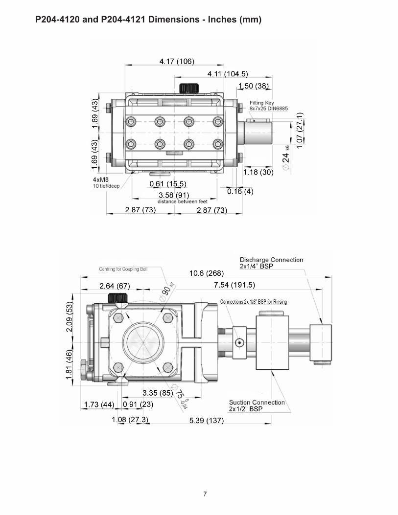
P204-4120 and P204-4121 Dimensions - Inches (mm)
06/19 P204-4120_P204-4121.indd
GIANT INDUSTRIES LIMITED WARRANTYGiant Industries, Inc. pumps and accessories are warranted by the manufacturer to be free from defects in workmanship and material as follows:
1. For portable pressure washers and self-serve car wash applications, the discharge manifolds will never fail, period. If they ever fail, we will replace them free of charge. Our other pump parts, used in portable pressure washers and in car wash applications, are warranted for five years from the date of shipment for all pumps used in NON-SALINE, clean water applications.
2. One (1) year from the date of shipment for all other Giant industrial and consumer pumps.
3. Six (6) months from the date of shipment for all rebuilt pumps.4. Ninety (90) days from the date of shipment for all Giant accessories.
This warranty is limited to repair or replacement of pumps and accessories of which the manufacturer’s evaluation shows were defective at the time of shipment by the manufacturer. The following items are NOT covered or will void the warranty:
1. Defects caused by negligence or fault of the buyer or third party.2. Normal wear and tear to standard wear parts.3. Use of repair parts other than those manufactured or authorized by Giant.4. Improper use of the product as a component part.5. Changes or modifications made by the customer or third party.6. The operation of pumps and or accessories exceeding the specifications
set forth in the Operations Manuals provided by Giant Industries, Inc.
Liability under this warranty is on all non-wear parts and limited to the replacement or repair of those products returned freight prepaid to Giant Industries which are deemed to be defective due to workmanship or failure of material. A Returned Goods Authorization (R.G.A.) number and completed warranty evaluation form is required prior to the return to Giant Industries of all products under warranty consideration. Call (419)-531-4600 or fax (419)-531-6836 to obtain an R.G.A. number.
Repair or replacement of defective products as provided is the sole and exclusive remedy provided hereunder and the MANUFACTURER SHALL NOT BE LIABLE FOR FURTHER LOSS, DAMAGES, OR EXPENSES, INCLUDING INCIDENTAL AND CONSEQUENTIAL DAMAGES DIRECTLY OR INDIRECTLY ARISING FROM THE SALE OR USE OF THIS PRODUCT.
THE LIMITED WARRANTY SET FORTH HEREIN IS IN LIEU OF ALL OTHER WARRANTIES OR REPRESENTATION, EXPRESS OR IMPLIED, INCLUDING WITHOUT LIMITATION ANY WARRANTIES OR MERCHANTABILITY OR FITNESS FOR A PARTICULAR PURPOSE AND ALL SUCH WARRANTIES ARE HEREBY DISCLAIMED AND EXCLUDED BY THE MANUFACTURER.
GIANT INDUSTRIES, INC., 900 N. Westwood Ave., Toledo, Ohio 43607PHONE (419) 531-4600, FAX (419) 531-6836, www.giantpumps.com© Copyright 2019 Giant Industries, Inc.