models of vascular pattern formation in leaves
TRANSCRIPT

HAL Id tel-00487510httpstelarchives-ouvertesfrtel-00487510
Submitted on 29 May 2010
HAL is a multi-disciplinary open accessarchive for the deposit and dissemination of sci-entific research documents whether they are pub-lished or not The documents may come fromteaching and research institutions in France orabroad or from public or private research centers
Lrsquoarchive ouverte pluridisciplinaire HAL estdestineacutee au deacutepocirct et agrave la diffusion de documentsscientifiques de niveau recherche publieacutes ou noneacutemanant des eacutetablissements drsquoenseignement et derecherche franccedilais ou eacutetrangers des laboratoirespublics ou priveacutes
Models of Vascular Pattern Formation in LeavesFranccedilois Feugier
To cite this versionFranccedilois Feugier Models of Vascular Pattern Formation in Leaves Mathematics [math] KyushuUniversity 2006 English tel-00487510
Doctorate thesis from the University of Paris 6
Biology
Defended by
Franccedilois G Feugier
For the degree of Philosophy Doctor from the University of Paris 6
Models of Vascular Pattern Formation in Leaves
Thesis Co Directors Jacob Koella Yoh Iwasa
Defended on the 14th of December 2006
Jury members Yves Couder (President) Steacutephane Douady (Referee) Christophe Godin (Referee) Jacob Koella (Inspector Co Director)
1
Preface5 General Introduction 6
1 Plant physiology6 11 Utility of a vascular system6 12 How does plant vascular network form8
2 Earlier and recent theoretical works9 13 Models of leaf vascular formation 9 14 Models of Phyllotaxis13
3 Terminology 15 4 Principle of canalization15
15 Principle of canalization17 16 How does a preferential path of auxin form19
- First article - 28 Self-organization of the vascular system in plant leaves Inter-dependent dynamics of auxin flux and carrier proteins29
Abstract 29 1 Introduction 30 2 Self-organization model for vein formation31
21 Cell-to-cell auxin flux 32 22 Dynamics of carrier protein concentrations 33 23 Auxin production rate34 24 Response functions35
3 Numerical analyses 37 31 Computer simulations 37 32 Typical patterns 38
4 Results 40 41 Linear flux and independent carrier protein regulation40 42 Saturating flux and independent carrier protein regulation41 43 Linear flux and carrier protein reallocation43 44 Saturating flux and carrier protein reallocation43
5 Discussion 45 51 Leaking46 52 Response function and branching 47 53 Higher auxin concentration in veins47
Acknowledgment 48 References 49
- Second article - 52 How canalization can make loops A new model of reticulated leaf vascular pattern formation53
Abstract 53 1 Introduction 54
2
2 Model 57 3 Simulations59 4 Results vein patterns 59
41 Alternative choices of the cell coupling function60 42 Parameter dependence63 43 Pattern with discontinuous veins65
5 Discussion 66 Acknowledgments 70 Appendix Supplementary materials 70 References 71
- Non-published material - 73
Appendices 74 Appendix A 74 Appendix B 75
Alternative models 80 1 Phyllotaxis model 80 2 Model of global allocation enhancement 82
General Discussion84
1 Vascular formation and cell differentiation 84 2 Tip-tip and pseudo tip-vein connections the saddle cell hypothesis 87 3 Pattern of veins emergence 88 4 Wounds and vascular bundle structures 89 5 Cell division criterion89 6 Veins thickness the roles of flux bifurcations and bipolarsaddle cells 90
6 1 The flux bifurcation90 6 2 The bipolarsaddle cell 93
7 Proposal of an experiment to check the existence of flux bifurcations94 8 Auxin hot spots96 9 Probable impact of phyllotaxis dynamics on main vein loops pattern97 10 Conclusion98 Acknowledgment 100 References for General introduction and General discussion 100 Reacutesumeacute en franccedilais103
3
4
Preface
I chose to make my thesis on models of leaf pattern formation for several reasons Firstly
the last paper published on leaf pattern models is from the 80s and until 2003 there was not much
publications on modeling of this phenomenon However during these 23 years progress has been
done in molecular biology and vascular formation in plants has been studied comprehensively in
A thaliana at the gene level New data were available to improve our understanding Therefore it
was time to restart working on that topic Secondly I am interested in self-organization processes
Plants are a nice example of self-assembled structures Just adding some phytohormone to plant
cells in culture starts to create order and roots and shoots come out from the anarchic callus
Thirdly I simply love plantshellip
This thesis is made out from two papers published in JTB
- Feugier FG Mochizuki A and Iwasa Y2005 Self-organization of the vascular
system in plant leaves Inter-dependent dynamics of auxin flux and carrier proteins Journal of
Theoretical Biology Volume 236 Issue 4 21 October 2005 Pages 366-375
- Feugier FG and Iwasa Y 2006 How canalization can make loops A new model of
reticulated leaf vascular pattern formation Journal of Theoretical Biology 243 235-244
I also added some non-published material taking in account recent publications
5
General Introduction
For all organisms resources are the essential condition for subsistence Once resources are
extracted from the environment they have to be distributed throughout all the parts of the organism
to supply each cell The best way Nature found to do so is to fill the body with a network of tubes
a vascular system The more complex the organism the more sophisticated the network
1 Plant physiology 11 Utility of a vascular system
Plants are autotrophic they do not need to eat any other living creature to survive they need
only three basics which are the carbon dioxide water and light to create their own organic matter
Plants assemble carbon dioxide molecules to create plant bricks cellulose Water is the second
ingredient the previous reaction but also plays a mechanical role to erect the plant by the creation of
a turgor pressure Finally light is the energy required for the reaction creating cellulose from the
two previous ingredients This reaction is called the photosynthesis and only plants can do that
This is the reason why plants are the lower level of the food chain
Leaves of the plant are the cellulose factories where photosynthesis takes place Ingredients
of the cellulose must meet there for the photosynthesis to occur But the plant faces a problem The
three basics required by the plant to build its cellulose and therefore grow are segregated in the
environment water is underground and carbon dioxide and light are above the ground Thus to
solve this problem and bring water in leaves for the photosynthesis to take place the plant uses an
upward network of pipes called xylem Water is absorbed by the roots and goes through the xylem
toward the leaves On the other hand carbon dioxide enters directly the leave through holes in the
leaf epidermis called the stomata Finally light is captured directly by the leaves to give the energy
required for the reaction Once all the basics are gathered bricks of cellulose are produced by
photosynthesis for the plant growth
6
Plants grow via the shoot apical meristems but also the roots Therefore bricks are needed in
the underground part of the plant to allow roots to elongate and explore new areas of the ground to
take more water and avoid competition with other plants roots Thus to convey bricks of cellulose
in the roots plants use a downward network this time called the phloem It happens that xylem
and phloem are on the same tracks in the vascular system but anti parallel
Figure 1 Leaf shape margin disposition and venation (From httpenwikipediaorgwikiLeaf)
7
The vascular system is particularly ramified in the leaves There it is not only a conveyor
but it plays the role of an exchange platform for gases and light Each cell doing photosynthesis
must be close to a vein to be supplied therefore the vascular network fills the flat surface of the leaf
as efficiently as possible Leaves and their network can take very divers shapes depending on the
plant species although its purposes are always the same (Figure 1)
12 How does plant vascular network form
Plant vascular network and animal vascular network are formed in very different fashions
due to different constraints
In animals it is formed by special cells that migrate and arrange together in a cylindrical cell
layer surrounding a lumen in order to create a tubular structure where fluids circulate On the other
hand given that plant cells cannot migrate and rearrange due to the cellulose wall surrounding
them the network must be assembled in a different way
During vascular formation files of cells - the pre-procambial cells - are selected among
surrounding equivalent cells to draw the place of the future vascular system Once they are selected
they eventually differentiate into cambium cells and divide longitudinally to give on one side the
xylem and on the other side the phloem Especially cells on the xylem side become empty and lose
the wall separating them creating as a result tubes going throughout the plant from the roots to the
shoots where fluids circulate Contrarily to the case of animal vascular system where fluids
circulate within a cylindrical layer of leaving cells in plants fluids circulate inside dead cells
But how does a plant manage to draw this network connecting the very end of the roots to
the shoots
The way these files of pre-procambial cells are selected among many equivalent cells has
been studied for several decades Some molecules having a strong effect on the vascular formation
have been discovered One of the most important morphogen is a phytohormone called auxin The
major macroscopic effect of auxin is the promotion of growth and its most remarkable
microscopic property is a polar movement through cells making auxin the only phytohormone
transported polarly from the shoots of the plant to the roots
8
This transportation is performed by another important molecule in plant morphogenesis
the auxin efflux carrier proteins of the PIN family Auxin can enter passively into a cell but needs
PIN carrier proteins to leave it Other carrier proteins have been discovered such as the AUX
family proteins that facilitate the entrance of auxin inside the cell But recently all the attention has
been focused on PIN proteins
Since auxin is produced in the shoots and travels to join the roots during the whole life of
the plant a constant flow of auxin is maintained The only cells likely to contribute actively to the
auxin transport during the plant life are the cambial cells the ones which were selected in first
place to give birth to the vascular system This perpetual transport may play several roles in the
plant such as for cell division axis and elongation and healing of wounds It is known that auxin can
also travel through the phloem but not polarly
Auxin and PIN proteins are also involved in phyllotaxis ndash the positioning of the leaves
around the stem The way these molecules interact to recruit the cells that form the vascular system
and also elaborate phyllotaxis is an issue for theoretical studies for more than thirty years Several
principles have been proposed ndash reaction diffusion canalization and mechanical constraints ndash to
explain this phenomenon based on empirical studies
2 Earlier and recent theoretical works
Here I review chronologically different theoretical approaches for the modeling of leaf
venation pattern and works on phyllotaxis Because the same actors operate in both phenomena
results from each are informative This short review deals with works published until 2006
13 Models of leaf vascular formation
In 1976 before any evidence of auxin transport by carrier proteins Meinhardt proposed a
model of leaf vascular formation based on Turing system (1952) In his model a substrate s auxin
for instance is produced in the whole leaf An activator a is produced from the substrate and
produces in turn an inhibitor h and a molecule for differentiation into vascular cells y The inhibitor
s prevents a to diffuse and create a massive differentiation Activator is at first supplied from the
petiole When a peak of a is formed it creates enough y so that y can be produced independently
9
from a by self catalysis Now y is high it consumes s decreasing in turn the production of a But
other non-differentiated surrounding cells contain a large amount of s Since a and s diffuse into
these cells a news peak of activator can take place in the non-differentiated cells and so on The
result is a moving peak of activator surrounded by a faster diffusing inhibitor and followed by a
trail of differentiated cells rich in y The peak can divide into two peaks going apart to form a tip
bifurcation or a peak can emerge along the formed trail to create a lateral branching The pattern
stops when the surface is evenly covered by a branching pattern consuming the substrate
Although there is no directional substrate movement the growth is clearly oriented toward
sites of high substrate concentration As a result two peaks will avoid colliding because substrate
concentration decreases as a peak comes close to another one and because of inhibitor diffusion
around each peak Therefore the model produces no connection
Mitchison (1980 1981) was the first to propose a model based on the canalization
hypothesis made by Sachs (1969) In his earliest model he assumes that permeability of the
interface between cells can change according to the squared value of the net flux through that
interface In a lattice of cells this facilitated diffusion principle can amplify a small perturbation in
an initially uniform laminar flow of auxin through the lattice creating eventually stable preferential
paths where auxin flows toward a sink Mitchison could obtain loops where auxin flows in two
opposite directions by moving punctual sources of auxin In a second model he introduces an
asymmetric diffusion between cells creating a polar transport of auxin Contrary to facilitated
diffusion where auxin movement is improved between two cells whatever the direction of the
movement in this second case auxin movement is improved in one direction This change creates
also preferential paths
Independently Honda and Yoshizato (1997) were working on the formation the branching
pattern of blood vessels in the wall of avian yolk sac They start their model with many islands of
cells between which blood is flowing from a source to a sink which is actually the heart of the
embryo They use the Kirchhoff law to calculate blood flux in each vessel Resistance of a vessel
increases when the blood flow in it decreases and vice versa The results show that some paths
between islands vanish whereas other spaces increase to form preferential blood paths Since this
model is mode only with loops (closed network) it shows many flux bifurcations contrary to the
canalization model proposed by Mitchison
10
By means of a completely different approach Markus et al (1999) used cellular automata
(CA) for the creation of leaf venation pattern This CA based on Turing system has four variables
activator inhibitor genetic switch and substrate and twelve rules to make possible autocatalysis
tip death dichotomous branching lateral branching chemotaxis and anastosmosis (vein
connections) In the model the role of the vein is to deplete from the field the auxin produced They
overcome the problem of vein connection which is the same problem for almost all models of leaf
venation by assuming that older veins leak auxin so as to attract younger surrounding veins They
obtain nice resulting patterns comparable to what is observed in real leaves
A more physical approach is proposed by Couder et al (2002) who suggest that the strain
that cells experience in a growing leaf can be the trigger of vascular differentiation This
assumption is based on the observation of cracks in silicon gels Surprisingly cracks have the same
constitutive property as veins in a leaf angle formed between three joined cracks are comparable to
the angles made by the meeting of three veins and the width of the cracks which is physically
related to the angles are of same order as the veins thickness (Bohn et al 2002) Furthermore
Bohn et al (2002) showed that this vein property is the same for any plant
Feugier et al (2005) started from Mitchisonrsquos model (1981) In their model a lattice of cell
can exchange auxin through their sides by using auxin carriers Carrier concentration on each side
can change according to the net flux through them They introduce carrier conservation in the cell
which improves the stability of the model and creates auxin preferential paths richer in auxin than
the surrounding cells contrarily the existing models Instead of using the upper row of the lattice as
auxin source and the lower row as auxin sink they use a global auxin production hypothesis and one
cell as a sink They study nine functional shapes of the self enhancement by the flux of the auxin
transport and conclude that only accelerating functions can create preferential paths In their
results the paths can branch to fill the whole lattice On the other hand they observe no vein
connection
Runions et al (2005) introduced an algorithm to generate realistic venation patterns In
their method veins grow toward the auxin sources in the leaf closest to their tip a source is
removed once a vein is close enough to it finally leaf grows following an anisotropic scaling and
new auxin source are placed in new spaces out of veinsrsquo range To obtain loops they assume that
veins connect by their tip on an auxin source To insure that two or more veins reach the source
they maintain the source until all the veins are arrived Then anastomose occurs The resulting
11
patterns are very realistic ranging from mono or dicotyledonous venation patterns to gingko
pattern
Rolland-Lagan and Prusinkiewicz (2005) started from Mitchisonrsquos models of auxin
facilitated diffusion and polar transport and added to both passive auxin diffusions They deduced
from their results that passive diffusion may play an important role in controlling veins that connect
auxin sources to sinks since they observe only one channel of auxin rather than several when
passive diffusion is high By setting a movement schedule to several sinks and sources during
simulations they obtain loops as seen in the Arabidopsis young cotyledon Finally by using two
auxin sources of different concentration they obtain a transient discontinuous venation
To mix reaction diffusion models and canalization Fujita and Mochizuki (2006) made a
model based on the diffusion of an activator of auxin transport This activator is produced by the
sum of the auxin fluxes in cells and diffuses amongst them If a cell experiences a low flux by
receiving the activator from nearby active cells it will increase its carrier allocation Orientation of
carrier allocation is done by calculating the direction vector of the mean flux vector of the cell
Carriers are allocated preferably on sides in the direction of the mean flux and to keep the total
amount of carrier constant carrier level on each side is normalized with the total amount of carriers
in the cell In their model all cells produce auxin Results show branching pattern wherein auxin
flows toward an auxin sink To obtain a netlike structure Fujita and Mochizuki start from a lattice
with random noise in auxin concentrations Noise provides some cells with a higher auxin
concentration than their neighbors Therefore due to flux enhancement cells start to flush away
auxin around them These circular waves propagate to the neighborhood until the moment all
waves front meet to form a network pattern covering the lattice in a way circles grow to meet and
form a Voronoi segmentation
To test an alternative of flux sensing by the cells Dimitrov et al (2006) propose a model
based on the sensing of auxin gradient rather than auxin flux and where auxin transport is done by
improved diffusion (Mitchison 1980) In their model they start from an already formed leaf areole
Cells in the center are undifferentiated and produce auxin and cells around forming the areole are
vascular and drain auxin In undifferentiated cells auxin diffuses passively The authors set a
threshold so that at some auxin gradient value between two cells they increase to a higher constant
value the diffusion coefficient between them As initial condition for the growth of the veins they
use an areole in which auxin has reached diffusion equilibrium In their results areas near the
12
border of the areole have the largest auxin gradient with the lowest concentration and the gradient
goes to zero as going toward the point with highest auxin concentration in the center of the areole
Cells in the areas with an auxin gradient larger than the threshold near the areole boundary start
increasing their diffusion coefficient toward the neighboring cell with which the threshold is
exceeded This behavior repeats from near to near climbing the gradient toward the center of the
areole to create a path where auxin flows in direction if the areole boundary Their model can
predict precisely where veins should emerge from the areole and where they should converge to
finally connect
14 Models of Phyllotaxis
Phyllotaxis has for a long time intrigued and numerous hypotheses for its formation have
been proposed A first idea is that mechanical forces due to growth in the shoot apical meristem
(SAM) can decide the place of emergence of primordia
Douady and Couder (1996) made a very elegant experiment to check whether placement of
primordia results from a processus of energy minimization in the meristem At the center of a
Teflon plate under a vertical magnetic field they drop periodically droplets of ferrofluid
representing the primordia The periodicity at witch they are dropped represents the growth speed
of the SAM In these conditions droplets are slowly attracted outward due the magnetic field
Droplets behave such as a dipole and repulse each other Hence at some dropping speed the
density of droplets on the plate increases and the spatial configuration demanding the lowest
energy should emerge The result shows nice spirals of phyllotaxis as observed in real plants The
divergence angle between droplets converges to the golden angle and the parastichies (phyllotactic
spirals) number changes following consecutive Fibonacci series numbers as the period between
two droplets decreases
This shows that new primordia try to emerge the furthest from already existing primordia
due to energy minimization (here magnetic field) Other phenomena can give identical results to
the previous experiment if the underlying physical principle is the same eg energy minimization
This is observed in buckling and Turing reaction-diffusion systems
Meinhardt (1998) also proposed a reaction-diffusion model for phyllotaxis by running a
typical activator-inhibitor model on a cylinder elongating at one end Starting from uniform initial
13
conditions and according to parameters peaks of activator emerge following a distichous
decussate or phyllotactic spiral pattern during elongation of the cylinder Peaks of activator emerge
in the areas of lowest inhibitor concentration which is the furthest from other activator peaks
(since peaks of activator are surrounded by high inhibitor concentration) This principle is the same
as the one proposed by Douady and Couder in their experiment
Shipman et al (2005) proposed a model based on the buckling pattern that minimizes
elastic energy Constraints in the growing SAM could generate a buckling that can induce special
behavior on cells such as growth and differentiation
Since the observation of a particular layout of PIN1 proteins in the tunica that presages the
emergence of primordia of leaves (Reinhardtb et al 2003) new modeling based on auxin transport
by PIN1 has been applied to phyllotaxis
Accumulation of auxin in the tunica is thought to give birth to leaf primordia To check this
hypothesis Barbier de Reuille et al (2006) verified whether the observed layout of PIN1 in the
tunica leads really to the accumulation of auxin presaging leaf primordia To do so they analyzed a
real SAM by computer and constructed a map of connections of each cell with its neighbors and
PIN concentration in each connection Using this map they ran dynamics of passive auxin diffusion
and auxin transport with PIN1 until steady state is reached Results show indeed auxin
accumulation in area of future primordia Furthermore they confirm the experimental fact
(Reinhardta et al 2003) that the summit of the SAM has no influence on the pattern of auxin
accumulation
Joumlnsson et al (2006) propose a model of phyllotaxis based on dynamics of active auxin
transport and passive diffusion In this model each cell contains a pool of free PIN1 carrier proteins
Allocation of carriers on one side of the cell depends in a monotonically increasing fashion on the
concentration of auxin in the neighboring cell on that side Thus if two cells have a slightly
different auxin concentration the one with a lower level will send more auxin toward the second
with a higher level As a result auxin converges toward areas of high concentration to form peaks
of auxin To estimate the parameters of their model they make a template of an observed SAM by
computer with the connection map of the cells and use an optimization algorithm After
estimation of the parameters they run their model on a 3D shape representing the SAM on which
all cells can divide and produce auxin Results show while elongation of the shape repeated
14
emergence of auxin concentration peaks following a spiral or a whorled configuration according to
parameters
Smith et al (2006) also proposed a model where auxin is pumped preferably toward cells
with high auxin concentration They run their 2D model by mapping it on a 3D growing shape
representing a SAM where cells divide They use different rates of auxin production according to
the area (central zone peripheral and proximal) of the SAM Their results show very realistic
patterns of all the different types of phyllotaxis
3 Terminology
In the following I deal often with the words ldquobifurcationrdquo and ldquojunctionrdquo To avoid any
confusion I clarify their use here
Usually a bifurcation is about a branch or a road which splits into two new branches or
roads such as a ldquoYrdquo shape If one walks upward on the ldquoYrdquo one meets a bifurcation But if one
walks downward on one branch of the ldquoYrdquo one meets a junction There is a crucial notion of
direction In the following when I use one of these words about some phenomenon (auxin
movement vein growth) I always take into account the direction of this phenomenon
For example if I look at salmons traveling from the sea to the source of a river I would say
the salmons will meet many bifurcations on their way whereas streams of water meet only
junctions It is just a matter of direction
If this looks simple to you (I hope) then you are ready for the following
4 Principle of canalization
To explain the formation of preferential paths of auxin Sachs proposed the canalization
hypothesis (Sachs 1969) inspired by the formation of rivers
Let us start with a readily observable example of this process On the beach at low tide it is
often possible to observe on the flat sand some branching patterns formed by the sea water flowing
back slowly to the sea (Figure 2) When a thin layer of water flows gently and evenly on a sand
slope if there is a small gutter in the sand water will rush into it due to gravity As a result the flow
increases in that gutter and sand is carried away increasing in turn the gutter size Since a larger
15
and deeper gutter receives more water the flow in the gutter increases and removes more sand and
so on creating a preferential path for water The increase in gutter size due to the water flow makes
this process a self enhancement process which is the foundation of the canalization hypothesis
Figure 2 branching pattern on the sand at low tide
A typical river (with erosion and sediment transport) is a branching network without any
closed loops A closed loop can be done by a bifurcating stream with the two branches connected
somewhere else downstream But this configuration is unstable and therefore transient Indeed at
the bifurcation point the stream of water will eventually flow into either one branch opening one
side of the loop
One can extend this canalization principle to plants vascular formation now In the case of
plants the role of water is played by auxin and the variation in the gutter size is mimicked by PIN1
carrier proteins concentration
16
The majority of plants have a reticulate network exhibiting many closed loops Since
several empirical results support the hypothesis of auxin canalization for the vascular system
formation their must be an additional process to canalization absent from river formation to
create stable closed loops of veins
15 Principle of canalization
To introduce canalization let us take an image with the simplest possible enhancement
model In first place consider a box in which one supplies water with a constant rate r the water
level being A and with two valves plugged at the bottom of the box with constant openings P1 and
P2 as shown in Figure 3a The dynamics of the water level follow
21 APAPrdtdA
minusminus=
where APi is the flux of water through valve i (i=12) resulting from the mass action law
between the height of water in the box and the valve opening value
r
P2P1
A
22 APJ =11 APJ =
r
P2P1
A( )1 PAϕ( )1 PAϕ ( )2 PAϕ( )2 PAϕ
22 APJ =11 APJ =
a) b)
Figure 3 Canalization example with a box and two valves Water is added in the box at a constant rate r a) The openings P1 and P2 are constant b) A machine measures the flux through the valves with a water while and controls their openings with the response function ( )iPAϕ
If one sets an opening for each valve P1 and P2 as supplying water with a constant rate box
fills and the water level reaches an equilibrium height which is the ratio of supply rate over the sum
of the valve openings
17
21
PPrA+
=
Now let us allow valve opening to change by introducing their dynamics Simplest opening
self enhancement for one valve would be the activation of its opening according to the flux of water
APi going through it The opening will respond to the flux going through it following a certain
behavior which one will call the response function ( )iPAϕ But in order to be a self enhancement
process as compared with a river broadening the response function needs to be a monotonically
increasing function of the flux The simplest one would be a linear response Therefore a basic
canalization model would be
( )
( )22
11
PAdt
dP
PAdtdP
ϕ
ϕ
=
=
where the simplest activation would be a response function proportional to the flux as
( ) ii APPA αϕ = with a α constant which one fixes to 1 for the following These equations are the
essence of self enhancement with the flux But in these conditions the box will fill for ever if the
valves are initially closed or the valves will remain opened even after water supply has stopped
and the box is empty Thus for a slightly more robust model one needs to guaranty that valves
never close completely neither stay wide opened for ever To do so let us introduce a ground value
q for the openings so the valves never close completely and a decay of the openings so the valves
never stay opened when the flux is null The system becomes
( )
( ) 222
111
PqPAdt
dP
PqPAdtdP
minus+=
minus+=
ϕ
ϕ
This system is the one proposed by Mitchison in 1981 One can increase complexity by
adding other variables in the response function term as well as changing the rest of the dynamics
18
but this simple self enhancement model offers a simple and intuitive approach to start studying vein
pattern formation with canalization
16 How does a preferential path of auxin form
To explain how flux self enhancement creates a preferential let us use the box introduced
earlier
The system reaches a steady state with
2
2
2
1
rqPP
rqrA
+==
+=
One remarks that what ever the value of r and the initial openings of each valve the both valves
converge to the same opening at steady state
Now let us try an accelerating response function valves will change there opening
according to the squared flux of water going through them In that case dynamics of water level is
unchanged but the response function becomes ( ) ( )2 ii APPA =ϕ
In this situation the steady state offers a more surprising particularity explained in more
mathematical details in Appendix B Now valves openings value at the steady state depend on
water supply rate and noise in the openings
- If r is below some threshold both valves will end up stably with the same opening
- If r is above some threshold the valve having initially a larger opening than the other
one will end up full opened whilst the other one will end up to the minimal opening (cf
Appendix B)
Finally a decelerating response function such as ( ) ii APPA =ϕ gives always a steady
state with both valve openings equal
The three types of response function give completely different steady states With the linear
response function both valves end up with the same opening whatever the initial conditions and the
water supply value With the quadratic response function valves behave similar to the linear
19
response when the supply of water is small but with a larger supply value the equality of the
openings becomes an unstable situation and one of the valves ldquowinsrdquo And finally the square root
response gives also equality of the two valves at steady state
Let us explain these results more intuitively The valve opening is clearly self-enhanced
since a wider valve creates a larger flux and a larger flux creates a larger response to open the
valves One also understands intuitively that the lower the level of water in the box the more stable
the system Therefore to have a low level of water one needs the total outward flux (the sum of
both fluxes) to be the largest Thus because the sum of he openings is proportional to the total
response totϕ the total flux 21 JJJtot += is proportional to totϕ eg tottotJ ϕprop As a result to get
the lower level of water one needs to be the largest hence totJ totϕ has to be maximum Let us try
to find the value of he fluxes for which totϕ is maximal with a fixed in the case of the linear
response an accelerating (squared) response and decelerating (square-rooted) response
totJ
Let be the flux through valve i and ii APJ = 21 JJJtot += be the total outward flux so
In the case of the linear response 12 JJJ tot minus= totϕ is equal to the sum of the fluxes
tottot JJJ =+= 21ϕ One can notice that whatever the value of J1 (and implicitly J2) totϕ is equal to
which is constant Therefore the total response totJ totϕ cannot be maximized
In the quadratic response case totϕ is equal to the sum of the squared fluxes
One can see that ( 21
21
22
21 JJJJJ tottot minus+=+=ϕ ) totϕ is maximal when or when
Therefore the total response is the largest and consequently the total
opening when only one of the two valves is opened and takes the total outward flux When the
system ends up with one valve wide opened and the other one nearly closed the configuration is
stable Indeed if the larger opening starts to decrease water level will increase in the box and the
flux through both valves will also increase But due to the non linearity of the response the larger
opening will open back faster than the smaller one taking more flux and staying the larger Then
the level of water will come back to the previous level
totJJ =1
tottottot JJJJJ =minus=minus= 012
20
Figure 4 Profile of the total response depending on either the linear square or square root response functions 3=totJ
Finally when looking at the square root response function totϕ will look like
1121 JJJJJ tottot minus+=+=ϕ In this case totϕ is maximized when 221totJJJ == This
gives the reverse result to the squared response function The Figure 4 illustrates all the cases
To summarize when the activation is quadratic one valve opens more than the sum of two
valves openings Therefore the lowest water level is reached only when one of the both valves is
fully opened and the other one is closed In the linear response case the openings tend to have the
same value but actually any opening values that sum up to are equivalent as seen in totJ Figure 4
and give the lowest water level Finally with the square root response both openings have to be
equal for the lowest water level By the way in the current model valve never close completely but
settle down to the minimum opening q
The same situation occurs for a box with n valves When the water supply is large with a
square root response all the valves tend to open equivalently whereas with the linear response all
the valves end up to any opening as long as their sum equals the total out flux and at last with a
21
quadratic response only one valve becomes fully opened and all the others n-1 pipes converge to
the smallest opening possible in the model which is q
In the system with quadratic response of the valve opening in regard to the flux the
threshold of water supply and therefore the flux through each valve is critical below this
threshold the flux is low the system behaves similarly to the linear regulation and noise in the
openings has no effect whereas above this threshold flux through valve is large the system
becomes unstable and sensitive to noise so as soon has the symmetry is broken it moves in the
situation where only one valve wins against all the others
So far we were speaking about a system unable to produce any spatial pattern because
deprived of dimension Now instead of using only one box let us use several square boxes arranged
together like a chess board (Figure 5a) For reasons which become clear later let us forget the
valves and use pumps between the boxes Each box has an outward pump toward each of its
neighboring boxes The net flux between two boxes i and j is defined as
jijijijinetij PAPAJJJ minus=minus=
where is the strength of the pumping from box i to box j If the net flux is negative one sets the
response function to null so the pump strength decreases toward a minimum q
ijP
Furthermore water is supplied in every box with the same constant rate and only one of
them on the border of the chess board the box 0 has a hole in it preventing it to fill with water
(Figure 5a) The question is given that we know the behavior of one box emerging from the type of
the response function what is going to happen in this situation where each box interacts with its
neighbors
Let us see what happens when one uses the linear response function in such a system As
soon as water is supplied boxes fill up except for the box 0 having a hole in it (Figure 5a) Since
box 0 is leaking its level of water is always below the one of its neighboring boxes As a result
boxes 11 12 and 13 will start to flow in box 0 (Figure 5b) Due to this flux through the pumps each
one will strengthen proportionally to the positive net flux between each box 1i and the sink Now
that the 1i boxes lose water into the box 0 their level is lower than boxes 2i The same process
continues from near to near to the whole chess board The emerging flow pattern shows no
preferential paths and each box mean flux vector is oriented toward the box 0 The mean flux
22
vector of a box is a vector centered on the middle of a box and taking the sum of the positive net
fluxes value on each opposite side as coordinates
0 11 0 13
12
21 0 25
22 24
23
11 13
12
31 37
32 36
33 35
34
21 0 25
22 24
23
11 13
12
41 49
42 48
43 47
44 46
45
31 37
32 36
33 35
34
21 0 25
22 24
23
11 13
12
a) b)
d)
c)
e)
Figure 5 Pattern obtained with a linear response function The pattern grows at each stop from the center Boxes are ranked in a radial fashion from the cell 0 at the bottom-center to the periphery and the indices are from the left to the right Arrows represent the net fluxes between the boxes Blue color represents pumping
23
boxes A rough idea of the length of each horizontal and vertical arrow can be given by ( ) rankcos θminus and
( ) ranksin θminus respectively with up-right positive direction and θ being the angle with the horizontal centered on box 0 a) - e) water is supplied everywhere Box 0 has a hole in it
What happens now with the quadratic response function Previously in the example of
Figure 3b with the quadratic response function we noticed the presence of a threshold of the water
supply above which the flux becomes high enough so only one valve ends opened and the other
tends to close up The box goes through this threshold if the value of the water supply increases
increasing in turn the out flux In the case of our lattice of boxes the water supply for one box
includes also the quantity of water received from the neighbors Let us assume for simplicity that
once a box receives more than one unit of flux (for example one box with two outward fluxes sends
half a unit of flux per side) the total amount of water received (water supply + sum of incoming
fluxes from the neighbors) can create a sufficiently large net flux with another downstream box so
the system is above the threshold making the pump with the largest net flux to work harder and the
others to shut down the box becomes polar
Let us see step by step on the
Figure 6 the pattern obtained with a quadratic response function For a better understanding
they are three steps to repeat as a loop first establish the zone in which boxes do not have the same
water level to decide the orientation of the fluxes second find the boxes receiving water from
more than one neighbor third set a polarity to these boxes and reorient the arrows of all the other
boxes according to the changes due to the new polar boxes I will principally deal with the left half
of the lattice since it holds for the right half by symmetry
In a) one starts supplying the water into all the boxes and box 0 remains with a lower level
of water due to its hole b) As a result water from boxes 11 12 and 13 flows into box 0 One notices
that box 0 receives water from more than one box so it becomes polar c) In turn water level
decreases in boxes 1i and now boxes 2i flow into box 1i Boxes 1i can become polar d) Since boxes
2i lose water into boxes 1i their water level is lower than boxes 3i Therefore boxes 3i start sending
water into boxes 2i e) Boxes 21 23 and 25 receive enough water to become polar One can see now
the emergence of preferential paths of water As seen previously a box with quadratic response
function under the threshold gives a behavior similar to the one with linear response function
Knowing that one can see that the outward flux of box 33 should be roughly equal to the sum of the
two outward fluxes of box 22 Therefore one can conclude that they have the same water level and
24
thus there is no flux between them Same thing happens for boxes 22 and 32 f) Now that 3i boxes
lose water their levels become low and boxes 4i start pumping water toward them Boxes 32 and
33 receive both 1 unit of flux But the symmetry is broken when looking at the surrounding boxes
of 32 and 33 Box 34 receives 2 units of water though box 31 receives 15 which means that box 34
has a higher level of water than box 31 Due to this level difference box 44 will actually send more
water in box 33 because the level difference is advantageous than in box 34 Symmetrically box
42 will actually send more water in box 32 than in box 31 But due to the higher water level in
boxes 34 than in 31 box 44 will send more water in box 33 than box 42 will send in box 32 As a
result both boxes receive more than one unit of flux but box 33 receives more water than box 32
allowing it to become polar first Box 31 receives also enough water to become polar g) We just
met the reasons why preferential path can branch and it is greatly helped by symmetry breaking
Now that new polar boxes appeared other boxes reorient their fluxes toward them h) Boxes 5i
start pumping toward boxes 4i One easily sees that boxes 41 43 and 45 have the required
conditions to become polar i) If we continue using the previous rules the tips of the water
preferential paths keeps on bifurcate and paths elongate until the pattern fills the whole lattice
0 11 0 13
12
21 0 25
22 24
23
11 13
12
31 37
32 36
33 35
34
21 0 25
22 24
23
11 13
12
a) b)
c) d)
25
31 37
32 36
33 35
34
21 0 25
22 24
23
11 13
12
41 49
42 48
43 47
44 46
45
31 37
32 36
33 35
34
21 0 25
22 24
23
11 13
12
e) f)
41 49
42 48
43 47
44 46
45
31 37
32 36
33 35
34
21 0 25
22 24
23
11 13
12
51 511
52 510
53 59
54 58
55 57
56
41 49
42 48
43 47
44 46
45
31 37
32 36
33 35
34
21 0 25
22 24
23
11 13
12
g) h)
51 511
52 510
53 59
54 58
55 57
56
41 49
42 48
43 47
44 46
45
31 37
32 36
33 35
34
21 0 25
22 24
23
11 13
12
i)
Figure 6 Pattern obtained with a quadratic response function The pattern grows at each stop from the center Boxes are numerated in a radial fashion from the cell 0 at the bottom-center to the periphery and the indices are from the left to the right Arrows represent the net fluxes between the boxes Blue color represents non polar boxes and black arrows are their fluxes Green color represents polar boxes and red arrows are their only outward flux a) - i) water is supplied everywhere Box 0 has a hole in it
26
It is clear that although the tip of the preferential path elongates and bifurcates it does not
mean that boxes are moving It means that from near to near as we saw the state of the boxes will
change from non polar to polar creating the preferential path where water flows better and where
the tip is the last box which became polar The tip is the place where the transition between these
two states occurs
The understanding of the behavior at a microscopic scale (one box) is very enlightening for
the comprehension of a much more complicated behavior at a macroscopic scale (many boxes)
Finally one can see the difference between the self enhancement of the flux and canalization
Canalization is a flux self enhancement process but flux self enhancement is not necessarily
canalization For example linear response function does not give any preferential paths therefore
it is not a canalization process although it does flux self enhancement Quadratic response function
does give preferential paths therefore it is a canalization process as well as it is a self enhancement
process Canalization does not occur in any flux self enhancements Conditions of occurrence are
discussed in Appendix B
Now that we saw what becomes of a lattice of boxes with water and pumps let us at last
investigate models of canalization based on what we saw previously and extend it to the case of
leaves Boxes become cells water becomes the auxin pumps become auxin efflux carriers PIN1
and the response function becomes what the cell does with its auxin
In the first article included in this thesis I deal with models based on flux self enhancement
I verify whether this process transposed to a hormone and its carriers can create an acceptable
pattern and the conditions of emergence
In the second paper I extend a model so that it can create a reticulate network by adding a
parsimonious change in the way an evolutionary jump could do
All reference numberc (figures numbers tableshellip) are internal to each article
27
- First article -
28
Self-organization of the vascular system in plant leaves Inter-dependent dynamics
of auxin flux and carrier proteins
Francois G Feugier A Mochizuki Y Iwasa
Abstract
The vegetative hormone Auxin is involved in vascular tissues formation throughout the plant
Trans-membrane carrier proteins transporting auxin from cell to cell and distributed asymmetrically around
each cell give to auxin a polarized movement in tissues creating streams of auxin that presume future vascular
bundles According to the canalization hypothesis auxin transport ability of cells is thought to increase with
auxin flux resulting in the self-enhancement of this flux along auxin paths In this study we evaluate a series of
models based on canalization hypothesis using carrier proteins under different assumptions concerning auxin
flux formation and carrier protein dynamics Simulations are run on a hexagonal lattice with uniform auxin
production A single cell located in the margin of the lattice indicates the petiole and acts as an auxin sink The
main results are (1) We obtain branching auxin distribution patterns (2) The type of self-enhancement
described by the functional form of the carrier proteins regulation responding to the auxin flux intensity in
different parts of a cell has a strong effect on the possibility of generating the branching patterns For response
functions with acceleration in the increase of carrier protein numbers compared to the auxin flux branching
patterns are likely to be generated For linear or decelerating response functions no branching patterns are
formed (3) When branching patterns are formed auxin distribution greatly differs between the case in which
the number of carrier proteins in different parts of a cell are regulated independently and the case in which
different parts of a cell compete for a limited number of carrier proteins In the former case the auxin level is
lower in veins than in the surrounding tissue while in the latter the auxin is present in greater abundance in
veins These results suggest that canalization is a good candidate for describing plant vein pattern formation
29
1 Introduction
The self-assembled vascular network of higher plants displays very diverse patterns such
as parallel veins branching veins and reticulated networks One of the principal actors in the
development of those structures is the phytohormone auxin (Jacobs 1952 Sachs 1975 Mitchison
1981 Uggla et al 1996 Sieburth 1999 Avsian-Kretchmer et al 2002 Fukuda 2004) Applying
ectopic auxin to vegetative tissue can initiate the development of vascular bundles (Sachs 1975)
To understand the mechanisms behind this vascular tissue formation with the action of auxin
molecular biologists created many mutants which exhibited abnormal venation (Carland et al
1999 Berleth et al 2000 Deyholos et al 2000 Steynen and Schultz 2003) Auxin is a particular
hormone transported in a polar fashion by a protein named PIN1 capable of driving auxin out of
the cell (Mitchison 1980b 1981 Sachs 1991 Goldsmith 1997 Berleth et al 2000 Morris
2000) Auxin entering a cell from its apical side is not pumped back toward the side of entry but is
transported out by the efflux protein PIN1 present in the membrane at the basal side of the cell
Inhibiting PIN1 dramatically changes the shape of the vascular network (Mattson et al 1999)
The canalization hypothesis (Sachs 1975 1981 1991) states that cells with a higher flux of
auxin than their neighbors become specialized in auxin transport and turn into an auxin sink for
normal surrounding cells At this point it remains unclear what triggers this shift in the cell
behavior but the result would create preferential paths which lead auxin toward the petiole
A similar self-organization process of network pattern formation has been discussed by
Honda and Yoshizato (1997) as well as Kobayashi (2000) These discussions concern the
formation of blood vessel networks in the yolk of chicken eggs They start within a population of
non-joined cells between which blood can circulate forming a network of fine vessels If one path
(eg vessel) is wider than other competing paths then the flux through this path increases relative
to the other competing paths The result is a positive feedback increased flux stimulates a
broadening in the pathwaysrsquo diameter which in turn further enhances flux rate In contrast narrow
paths with a weak flux will decrease in diameter and eventually disappear This model is
somehow similar to the self-organization of leaf vein pattern formation generated by the action of
auxin except that the blood vessel network of Honda and Yoshizatorsquos model assumed no polarized
cellular transport of blood (ie only passive isotropic blood movement outside of the cells)
30
Mitchison proposed a similar vein formation model (Mitchison 1980a) based on Sachsrsquo
canalization hypothesis with isotropic auxin movements between cells He extended this model
(Mitchison 1981) by adding anisotropy in auxin transport In his model cells exchange auxin with
their neighbors They increase the permeability of their plasma membrane on the side where the
net flux of auxin with a neighboring cell through the membrane is positive and large Mitchison
performed simulations in a small square lattice of size 4 cells by 5 cells In this model the top row
of cells was linked to an auxin source of a fixed concentration and the bottom row was linked to a
sink of zero auxin concentration Starting with a laminar flow of auxin from top to bottom
Mitchison demonstrated that a small perturbation grows to form a preferential path of auxin
Subsequently auxin supplied in the top margin of the lattice first flows into the preferential path
and then streams down to the sink To create a preferential auxin path Mitchison argued that auxin
concentration in the cells of the path must be lower than concentration in adjacent cells in order to
create an inward flux of auxin into the path To achieve this he assumed that the permeability of
membranes regions increases as a quadratic function of auxin flux passing through it He reported
neither branching patterns nor a network of veins probably because the lattice size adopted in his
numerical analyses of the model was too small to show these phenomena
In this paper we consider a hexagonal lattice of about 3000 cells which is sufficiently large
to study the formation of two-dimensional patterns In our model auxin is produced in all cells in
the lattice and flows out of the lattice through a sink corresponding to the petiole We consider the
abundance of efflux carrier proteins such as PIN1 and assume that they change their abundance in
response to the auxin net flux We explore nine different functional forms that describe the
dependence of carrier protein abundance on the flux We also examine two different ways of
controlling carrier protein numbers PIN1 and two types of auxin transport reaction kinetics by
PIN1 Finally we identify conditions in which branching veins can be formed
2 Self-organization model for vein formation
Mitchison (1981) considered the external movement of auxin with changes in membranes
permeability from one cell to another and also the internal diffusion of auxin between different
sides of a cell Here we simplify Mitchisonrsquos model by assuming that auxin concentration is
uniform within each cell We consider a hexagonal lattice of cells in which a cell i has a
31
concentration Ai of auxin a concentrations ci of efflux carrier proteins free in cytoplasm and a
concentration Pij of efflux carrier proteins embedded in the membrane on side j (j = 12hellip6) and
active as carriers We assume that cells use the net flux of auxin going through each side of their
membrane as a cue to produce or to reallocate the carrier proteins appropriately
21 Cell-to-cell auxin flux
Concerning the auxin flux from cell i to cell on side j the simplest assumption is a linear
form derived from the mass action law between auxin and carrier proteins
Linear flux
( ijjjiiji PAPAJ 21
minus= α ) (1a)
where Jij is the net flux of auxin from cell i to cell j α is the efficiency of a carrier protein
This equation is derived from the following argument A single carrier protein in cell i causes
efflux iAα of auxin The side of cell i facing cell j contains Pij carrier proteins and hence the auxin
efflux from cell i to the intercellular space between i and j is jii PA α Auxin moving out of the cell
into the intercellular space will randomly enter the next cell or return to the cell it originated from
If decay of auxin is neglected half of the auxin efflux is effectively pumped into the neighboring
cell j Considering a similar process caused by carrier proteins in cell j in the side facing to cell i
we obtain Eq (1a) as the net flux of auxin
Since carriers are enzymes and auxin is substrate we also investigated a
MichaelisndashMenten form for the reaction of auxin transport out of the cell Hence the rate of
transport would saturate for a high auxin concentration as follows
Saturating flux
⎟⎟⎠
⎞⎜⎜⎝
⎛
+minus
+= ij
j
jji
i
iji P
AkA
PAk
AJ 21α (1b)
32
where α is the maximum speed of the transport reaction achieved when auxin
concentration is very high The Michaelis-Menten constant k indicates the auxin concentration
achieving half of the maximum speed If the auxin concentration is high enough to saturate the
carriers the total amount of auxin transported through the carriers on one side of the cell is close to
jiP α
22 Dynamics of carrier protein concentrations
We consider two types of dynamics for the carriers First we assume that carriers of
different sides of a cell are regulated independently
Independent regulation model
( )( jimjiji PqJ
dtdP
minus+= ϕλ ) (2)
where λ is the turnover rate at which the carrier protein abundance responds to the auxin
flux qm is the minimum density of carriers always embedded in the plasma membrane ( )jiJ ϕ is
an increasing function of flux Jij describing the response of the cell to the flux by producing new
carrier proteins or by allocating existing free proteins within the cytoplasm to the cell membrane
We will examine different possible functions for ( )jiJ ϕ later
An alternative assumption is that the number of carrier proteins per cell is fixed or changes
very slowly over time (Geldner et al 2001) In this case different sides of a cell must compete
with each other for allocation of free carrier proteins We consider the following dynamics of a
free carrier proteins pool and the carrier proteins on different sides of the cell
Reallocation model
( )( ⎟⎟⎠
⎞⎜⎜⎝
⎛+minus= sum sum
= =
n
j
n
jajiiji
i qJPdt
d1 1
ϕψλψ ) (3a)
( )( )( jiajiiji PqJ
dtdP
minus+= ϕψλ ) (3b)
33
Here iψ is the abundance of free and inactive carrier proteins located in a cytoplasm
compartment Carrier proteins leave the cell membrane by mass action law to join the free carrier
pool and are allocated from the free pool to the cell membrane with a rate depending on ( )jiJ ϕ qa
is the minimum carrier allocation value when there is no flux Under the Reallocation model the
number of carrier proteins is fixed and thus
sum=
minus=n
j
jii
dtdP
dtd
1
ψ
23 Auxin production rate
We assume that in the beginning stages of vein formation cells contain some auxin and are
able to produce it Only one cell located at the boundary of the domain is the auxin sink and has
its concentration of auxin set to zero It represents the petiole of the leaf through which auxin is
flushed away
We assume two steps in auxin production First let Si be the concentration in cell i of a
hypothetical enzyme that is responsible for synthesizing auxin The production of Si is inhibited by
auxin and follows Eq (4)
ieq
ii SAAs
dtdS
δminus⎥⎥⎦
⎤
⎢⎢⎣
⎡minus=
+
1 (4)
where [ ] for and xx =+ 0gtx [ ] 0=+x for 0lex s is the maximum rate at which the auxin
synthesizing enzymes Si are produced Aeq is the threshold auxin concentration such that if AigtAeq
Si production is shut down δ is the decay rate of Si Second auxin in cell i is synthesized by Si and
follows the dynamics of Eq (5)
sum=
minus=n
jjii
i JSdt
dA1
ε (5)
34
where ε is the efficiency of the auxin synthesizing enzyme Si
24 Response functions
The response function ϕ in Eqs (2) and (3) increases with auxin flux J At this point in
time sufficient knowledge of biological molecular processes is unavailable Hence we examine
many possible ϕ functions which differ in the manner that they increase with J
We consider nine functions of carrier protein production or carrier protein reallocation as
candidates for the response to the auxin flux (as given in Table 1 and illustrated in Fig 1) We
assume 0=ϕ if Jij is negative and we consider ϕ to be as in Table 1 when the net flux Jij is
positive In other terms the cell reacts only if the quantity of auxin going out through its membrane
is larger than the quantity of auxin received from outside
For the (1) linear function the production or allocation of carrier proteins increases in
proportion to the flux For the (2) square function the production or allocation of carrier proteins
increases in proportion to square flux (3) Curvilinear function has a derivative equal to zero at J =
0 behaving like a square function when J is small but increases linearly with J when J is large For
the (4) shifted linear function there is no carrier production or allocation if J is smaller than b and
production or reallocation increases linearly with J otherwise
The production or reallocation of carrier proteins is an increasing function of the flux J and
is given by ( )Jϕ in Eq (2) These are classified in four groups based on the behavior of ( ) JJ ϕ
a b h and k are parameters
For the (5) square root function the production or reallocation of carrier proteins increases
with J but the rate of increase becomes slower for a larger J For the (6) saturating function the
production or reallocation of carrier proteins increases rapidly when the flux is low and saturates to
an asymptote when the flux is high (7) Divergent S-function has a derivative equal zero at J = 0
and behaves like a square root function when J is large (8) S-shape function has a derivative equal
zero at J = 0 The production or allocation of carrier proteins is low for a small J accelerates when
J becomes larger and saturates for a large J Finally with (9) step function neither carrier protein
production nor reallocation occurs if J is smaller than b but carrier production or reallocation
occurs at a constant rate when J is greater than b
35
Among these nine functions (2) square (3) curvilinear and (4) shifted linear functions
share a common feature The function value is relatively small for a small J and rapidly increases
beyond some threshold Opposite to the previous are the cases for (5) square root function and (6)
saturating function where the function is rather high for a small J but increases slower as J
becomes large (7) Divergent S-function and (8) S-shape function contain a mixture of the two
previous groups The function is rather small for a small J increases as J becomes larger and
finally the rate of increase diminishes for a high J (9) Step function has a similar property
By noting the behavior of the ratio ( ) JJ ϕ these nine functions can be classified into four
types For response function (1) ( ) JJ ϕ is constant We call this function linear response
function For response functions (2)ndash(4) ( ) JJ ϕ increases with J We call these responses
accelerating response functions For response functions (5) and (6) ( ) JJ ϕ decreases with J We
call these responses decelerating response functions Finally for response functions (7)ndash(9)
( ) JJ ϕ is small for a small J then becomes large for an intermediate J and then becomes smaller
for a large J We call these responses S-like response functions
36
Fig 1 Different protein production response according to the auxin flux (a) Linear function (b)
square function (c) curvilinear function (d) shifted linear function (e) square root function (f) saturating
function (g) divergent lsquolsquoSrsquorsquo function (h) S-shape function (i) step function Horizontal axis is for auxin flux
3 Numerical analyses
31 Computer simulations
We performed the simulations on a hexagonal lattice of fixed size consisting of 2912 cells
plus one playing the role of the auxin sink all arranged inside an elliptic-shaped domain imitating
a leaf primordium Since we are mostly interested in the conditions of vein formation we did not
perform the numerical analysis on a growing domain
Each cell has 6 neighbors except those at the boundary of the leafdomain Cells having
one or more sides on the boundary cannot exchange auxin across it The sink cell corresponds to
the petiole of the leaf Its auxin concentration is fixed at 0 throughout the simulations
We also performed simulations on a smaller lattice of 230 cells plus one sink in order to
increase spatial resolution scale to appreciate the qualitative distribution of carrier proteins and
orientation of the mean fluxes of cells in the principal patterns
Initial concentration of auxin for all the cells is Ai = Aeq Aeq is set to different values
between simulations to give the least ambiguous results We initialize carrier protein abundance to
a constant for all useable sides of all cells (Pij = 01) This initial condition corresponds to the
37
equilibrium value of carrier protein concentration in the absence of auxin flux as we assume qm =
01 for the independent regulation model (Eq (2)) and iψ = 2 and qa = 005 for the reallocation
model (Eqs (3ab))
The simulations were stopped when the variables became extremely large when the
spatial pattern and all the variables became stationary when the pattern was static although
auxin was still accumulating or when leaking (Table 2) was observed before the pattern could be
disturbed We explored a wide range of parameters and attempted to grasp all the different typical
spatial patterns (see Section 32) We especially examined the parameter range which generates the
different branching patterns (Table 2)
32 Typical patterns
For an explanation of the different computer simulation results we introduced a
terminology listed in Table 2
Through the simulations with all our assumptions in a wide range of parameters the model
generated several typical spatial patterns which are as follows
(a) Laminar orientation pattern The mean flux (Table 2) of all the cells is oriented toward the
sink irrespective of their distance from it No veins (Table 2) are formed and cellular
concentration of auxin within the lattice remains uniform (Fig 2a) or an increasing
gradient toward the sink can occur with total concentration stabilized (Fig 2b) also
displayed was an increasing gradient toward the sink with an indefinite accumulation of
auxin over time (Fig 2b)
(b) V-pattern Cellular mean auxin flux is oriented parallel to the lattice sector lines (Table 2)
to which they are the closest Cells on the bisectrix of the sector lines are oriented toward
the sink and have a higher auxin concentration to that of their neighbors (Fig 2c)
(c) Branching pattern Veins grow and bifurcate from the sink to the periphery without
forming closed loops Auxin concentration is higher in veins than in the surrounding cells
(Fig 2d)
(d) Reversed branching pattern This is also a branching pattern but auxin levels are lower in
the veins than in the surrounding tissues (Fig 2e)
38
(e) Leaking pattern This pattern results from venous auxin leakage (Table 2) The total auxin
concentration can keep increasing with time Once leaking starts waves of auxin move
across the lattice destroying any pattern established
Table 2 Terminologies used in describing the results
Mean flux and orientationpolarization of a cell The vector having the carrier protein
concentrations of the 6 sides of the cell as coordinates If the cell has a high concentration of
carriers on one side only and just the basic concentration of carriers on the other sides then the cell
is strongly oriented (in one direction) and the mean flux shows the direction Preferential
pathvein A line of cells in which auxin flux is much higher than in surrounding cells and
homogeneously oriented to form a stream The downstream side of each cell is richer in carrier
proteins than the other sides Auxin concentration (not the flux) can be either higher or lower than
in the surrounding tissues
Sector lines The straight lines of slope 0 3minus and 3+ separating the hexagonal lattice
into 6 equal sectors
Leaking Initially veins are formed and then leaking starts A vein cell suddenly starts
pumping auxin out to the surrounding (non-vein) cells
Fig 2 Typical patterns observed with the models (a) Laminar orientation without gradient of auxin
(b) laminar orientation with gradient of auxin (c) V-pattern (d) reversed branching pattern (e) branching
pattern Light gray indicates high auxin concentration and dark gray low auxin concentration
39
4 Results
We carried out computer simulations of all the combinations of (1) the linear flux versus
saturating flux (2) independent carrier regulation versus competition for free carriers and (3) all
the nine response functions to the fluxes ie 36922 =timestimes cases in total In the following section
we explain the results using four main categories corresponding to the four possible combinations
of auxin flux dynamics and pump regulation and in each category we describe the results obtained
with the different response functions
41 Linear flux and independent carrier protein regulation
We first consider the case in which the flux is non-saturating (Eq (1a)) and the carrier
protein concentrations are regulated independently (Eq (2))
The results greatly depend on the choice of response function ( )Jϕ For the linear response
function (1) no preferential path (Table 2) is formed but we observe a laminar orientation of the
cellsrsquo mean flux toward the sink as seen in Fig 3a
For accelerating response functions ((2)ndash(4)) and the S-like response functions ((7)ndash(9))
the model can create veins and bifurcations if Aeq is sufficiently high giving rise to a reverse
branching pattern (Figs 3c and 4a b) For the accelerating response functions we observed that
cells belonging to a vein are strongly polarized containing most carrier proteins in a single
downstream side of the cell Also we often observed for these accelerating functions an extremely
rapid increase followed by a rapid decrease in the carrier proteins concentrations of cells near the
sink (see appendix A in third part for details) making simulations impossible for higher values of
Aeq The auxin concentration was also observed to be lower in the veins than in the surrounding
tissue
For S-like response functions ((7)ndash(9)) the model initially creates veins However if the
auxin flux is high enough veins begin to bifurcate and cells at the bifurcation points start leaking
(Fig 3f) Leaking destroys all the established vein patterns
In contrast with decelerating response functions ((5) and (6)) the model displayed paths of
high auxin concentration as a V-pattern but no branching of paths was observed (Figs 3b and 4c
d) Furthermore cells with a high auxin concentration are not strongly polarized and send out the
40
hormone through two sides Cells between the high concentration paths pump out auxin through
their three sides which face in the direction of the sink (Fig 4c d)
42 Saturating flux and independent carrier protein regulation
If we adopt the MichaelisndashMenten saturating flux as in Eq (1b) results of the 9 different
response functions ( )Jϕ are as follows
The linear response function gives laminar orientation (Fig 3a) as in the previous section
If α is too small no pattern occurs for the other response functions Therefore we set α
high enough for a pattern to develop Accelerating response functions ((2)ndash(4)) generate reverse
branching patterns (Figs 3c and 4a b) We still have an extremely rapid increase of carrier protein
concentrations followed by a rapid decrease causing simulations to stop even for a very small time
step The saturating response function (6) resulted in a V-pattern (same as Figs 3b and 4c d)
Auxin continues to accumulate over time in the two paths leading to the sink when Aeq is high
For S-like response functions ((7)ndash(9)) reverse branching veins are produced first (Figs 3c and 4a
b) and followed by leaking after veins bifurcate (Fig 3f) Finally the square root response
function (5) gives irregular unpredictable but symmetric patterns (Fig 3e) Groups of cells
become polarized toward the sink while others are polarized toward the opposite direction No
preferential paths are formed as each cell has several sides with a high carrier protein
concentration
41
Fig 3 Results of the numerical analysis The number of cells in the lattice is 2912 The leftmost cell of
the lattices is the sink of auxin corresponding to the petiole The white lines starting from the center of each
cell indicate the orientation of the mean flux of the cell Auxin level is represented by density plot Light
indicates higher level and dark indicates lower level (a) Laminar orientation obtained with linear flux (Eq
(1a)) independent carrier protein regulation (Eq (2)) and linear response function to the auxin flux ((1) in
Table 1) Aeq = 2 and s = 03 (b) V-pattern obtained with linear flux (Eq (1a)) independent carrier protein
regulation (Eq (2)) and saturating response function (6) Aeq = 2 s = 02 and h = 1 (c) Reverse branching
obtained with linear flux (Eq (1a)) independent carrier protein regulation (Eq (2)) and curvilinear response
function to the auxin flux (3) Aeq = 35 s = 07 h = 1 (d) Branching pattern obtained with linear flux (Eq (1a))
carrier protein reallocation (Eqs (3a) and (3b)) and curvilinear response function to the auxin flux (3) Aeq =
07 s = 018 h = 1 α = 6 and k = 005 (e) Chaotic pattern obtained with saturating flux (Eq (1b))
independent carrier protein regulation (Eq (2)) and the square root response function to the auxin flux (2) Aeq
= 196 s = 02 k = 1 (f) Leaking pattern obtained with linear flux (Eq (1a)) independent carrier protein
regulation (Eq (2)) and the lsquolsquoSrsquorsquo shape response function to the auxin flux (8) Aeq = 115 s = 017 and h = 1 In
all the simulations a = 1 α = 2 δ = 1 qm = 01 qa = 005 iψ = 2 λ = 1 and ε = 1 unless stated otherwise
42
43 Linear flux and carrier protein reallocation
Now let us consider the case in which cells contain a fixed number of carrier proteins
allocating them to any side according to auxin fluxes
Response function (1) gives a laminar orientation with an auxin gradient increasing toward
the sink The spatial patterns are similar to those described in the previous sections
The most striking difference between the results of the previous two sections and the
following two sections is the spatial distribution of auxin For the accelerating response functions
((2)ndash(4)) veins include higher levels of auxin than in the surrounding tissues and have an
increasing auxin concentration gradient as we move along a vein from the tip to the sink at
equilibrium auxin level is stabilized to a finite value (Fig 3d)
Decelerating response functions ((5) and (6)) generate again the V-pattern displayed in
Figs 3b and 4c d Auxin levels increase from the tips of the V-shape to the sink
S-like response functions ((7)ndash(9)) produce veins initially for a small Aeq (Fig 3d) and
following the branching process leaking occurs In the present case when a vein cell starts leaking
it pumps auxin into adjacent non-vein cells which in turn pump auxin back into the neighboring
not yet leaking vein cells Subsequently these adjacent vein cells start leaking When Aeq is not too
large this chain reaction can produce thicker veins Auxin accumulates in the lattice until the
leaking stops spreading or fills the entire leaf When Aeq is large the model does not start with a
branching pattern and generates only a V-patterns No destruction of the pattern occurs and auxin
levels are stabilized to a finite value
When k is large well-defined veins quickly form before any leaking occurs even for high
values of Aeq
44 Saturating flux and carrier protein reallocation
In all the cases we observed the unlimited accumulation of auxin over time in veins which
is due to the saturating flux function
43
Fig 4 Contrasts between auxin levels auxin fluxes and carrier protein concentrations in the case of
strongly polarized and weakly polarized cells The number of cells in the lattice is 230 The leftmost cell in the
lattices is the sink of auxin corresponding to the petiole On the left parts (a) and (c) auxin level is represented
by density plot Light indicates higher levels and dark indicates lower levels Mean auxin fluxes of cells are
indicated by white lines starting from the center of each cell On the right parts (b) and (d) the concentrations
of the carrier proteins on each of the six sides of the cells are indicated by the black lines starting fromthe
center of each cell For all parts (a b c and d) long white or black lines indicate respectively high mean auxin
flux or high carrier protein concentration on the corresponding side (a) and (b) Linear flux independent
carrier protein regulation square response function Aeq = 244 s = 055 qm = 01 a = 1 α = 2 In (b) the cells
exhibit only one side with a dominant carrier protein concentration Cells belonging to a vein have only one
carrier with a high concentration oriented downstream to the sink and the other carriers to the minimum
value hence cells are strongly polarized The mean fluxes are well superposed to the most abundant carrier
protein (c) and (d) Linear flux independent carrier protein regulation square root response function Aeq = 2 s
= 03 qm = 01 a = 1 α = 2 The mean fluxes in (c) are oriented toward the base of the leaf and not
preferentially toward the two lines rich in auxin Carrier protein concentrations in (d) show that each cell has
44
more than one side rich in carrier proteins hence cells are not strongly polarized Other parameters are a = 1
δ = 1 λ = 1 and ε = 1
Consequently veins have a higher auxin concentration than the surrounding cells
Response functions (1) (5) and (6) generated qualitatively similar patterns as described for these
functions in Section 41 and response function (2)ndash(4) and (7)ndash(9) generated patterns similar to
those described in Section 43 Although accelerating functions in Section 41 often gave rise to an
extremely rapid increase followed by sudden decrease in carrier protein abundance the
simulations using these functions in this section did not exhibited this feature
5 Discussion
We have studied the conditions in which the self-organization of a vascular system-like
pattern can be achieved by interrelated dynamics of auxin flux and carrier proteins This is based
on the hypothesis proposed by Sachs (1975) and studied by Mitchison (1981) We observed that
several assumptions of the model have strong effects on the possibility of developing vein patterns
similar to those observed in real plant leaves
First the model can generate stable inhomogeneous distributions of auxin resulting in
pathways that branch and avoid collision These pathways may have either lower or higher
concentrations of auxin relative to surrounding cells
Second the likelihood of obtaining veins is very sensitive to the regulation of carrier
protein concentrations by auxin flux as described by ( )Jϕ The accelerating and S-like response
functions (in Table 1 and shown in Fig 1b c d g h and i) can give rise to a pattern of branching
veins A linear response function can also maintain the pattern once it is created such as response
functions (2) and (3) In contrast for the decelerating response functions (shown in Fig 2e f) the
model generates mostly V-patterns that do not branch The accelerating and S-like response
functions differ from the decelerating response functions by the behavior of ( ) JJ ϕ near the
origin
Third when branching veins are formed there are two distinct cases concerning auxin
concentration in veins In reversed branching patterns such as Figs 3c and 4a b the concentration
of auxin is lower within veins than in the surrounding tissues This can occur when the number of
45
carrier proteins in any region of the cellrsquos membrane is regulated independently of the number of
proteins in other regions of the cell On the other hand if carrier protein regulation is achieved
mainly by competition for the allocation of free carrier proteins where an increase of carrier
proteins in a portion of the cellrsquos membrane tends to inhibit the increase of the number of carrier
proteins in other regions of the same cellrsquos membrane whilst the total number of proteins is fixed
then non-reversed branching patterns are likely to be formed This is demonstrated by Fig 3d
which corresponds to carrier protein Eqs (3a) and (3b) Although the veins are richer in auxin
they do not exhibit leaking if the accelerating response functions ((2)ndash(4)) are adopted
Fourth compared with the choices of response function and carrier protein regulation the
choice of linear or saturating flux as a function of auxin levels in two adjacent cells ie the choice
between Eqs (1a) and (1b) does not have a strong influence on the formation of vein patterns
Fifth there are many patterns that show leaking This can occur if a vein system is formed
and if the response functions is of S-like type ((7)ndash(9))
51 Leaking
In instances where leaking occurs a pulse will lsquolsquopushrsquorsquo away auxin from the vein creating
a wave with no preferential direction which starts from the leaking site and spreads among the
normal cells
Furthermore we often observed the formation of small cycles or rings of three or four
cells with circulating auxin creating self-enhanced isolated systems This is consistent with Sachsrsquo
observations on fragments of radish (explained in Mitchison 1981) When auxin is applied to one
side of the fragment the opposite side presents these kinds of vascular cell cycles This type of
vein formation caused by pulsing auxin out from the extremity of an elongating vein is not likely
to create well-structured branching veins To drive the auxin flushing tip of an elongating vein
toward the right direction (ie an auxin sink) cells receiving auxin from the tip of this vein need to
be lsquolsquopartially inducedrsquorsquo in some direction (Sachs 1991) in order to lead this veinrsquos auxin flow
correctly Otherwise the vein wanders and can eventually meet itself creating a ring with
circulating auxin
46
52 Response function and branching
We observed that the branching vein formation critically depends on the choice of response
function ( )Jϕ Concerning the reason why ( )Jϕ determines the formation of branching we may
develop the following intuitive argument Considering a cell that receives a strong flux from one
of its neighbors and has 5 other neighbors which are almost equivalent to each other The focal
cell tends to move carrier proteins into the 5 portions of the plasma membrane which are in contact
with its neighbors to redistribute the received flux among the five neighboring cells Then we ask
whether all of these 5 portions tend to equilibrate their outgoing auxin flux or if one of them
monopolizes the total flux If the response function increases faster than linear then one that
happens to have slightly more carrier proteins than the others will have a higher flux It will tend to
increase its carrier protein concentration more than proportionally resulting in the monopoly of
the auxin flux (se appendix B in third part for analysis) A preferential auxin path emerges and
possibly a branching pattern (Figs 3c d and 4a b) In the carrier reallocation model the monopoly
is reinforced by competition for free carrier proteins
53 Higher auxin concentration in veins
In the case of carrier reallocation model total carrier protein abundance is constant For a
strongly oriented cell all the carrier proteins are present on one side Thus the outgoing flux is
proportional only to the internal auxin concentration since carrier concentration on that side
becomes constant This allows an increase of cellular auxin concentration Subsequently we obtain
a branching pattern in which vein cells have a higher concentration of auxin than normal cells
This result is consistent with experimental observations (Uggla et al 1996
Avsian-Kretchmer et al 2002 Mattson et al 2003) It seems that a higher concentration of auxin
in the pre-procambial cells is necessary for correct orientation of cell division (Petrasek et al
2002) Note that this is contrary to the expectation of Mitchison (1981) who stated that the auxin
concentration needs to be lower in the preferential path than in the surrounding tissue as seen in
reversed branching patterns
According to our study branching patterns are formed when carrier proteins are regulated
by competition between regions of a cell membrane as given by the reallocation model (Eqs (3a)
47
and (3b)) whilst reverse branching patterns are formed when carrier proteins in different regions
of the cell membrane are regulated independently of the others (Eq (2)) Hence the experimental
results suggest that the carrier protein should be regulated by competition as given by Eqs (3ab)
which is consistent with another observation that the total number of proteins within a cell changes
very slowly (Geldner et al 2001) The rapid turnover between different parts of a cell needs to be
tested by more direct experiments
The theoretical study in this paper is just a beginning of a more comprehensive modeling of
the phenomena There are several points we need to address in future studies First we could find
conditions in which branching veins are formed and why in our study we found no closed loops
although loops are formed in the network of some plant leaves Second there are many mutants of
vein pattern formation especially in Arabidopsis Some of these mutants show discontinuous
veins (Carland et al 1999 Deyholos et al 2000 Koizumi et al 2000) which seem to be difficult
to produce using the model studied in this paper The reason may be that we consider a global and
uniform auxin production and not for instance only in the margin Tohya and Mochizuki (in
press) recently developed a reactionndashdiffusion model that is able to explain the formation of
discontinuous veins Fujita and Mochizuki (in press) studied the pattern formation produced by
auxin and its carrier protein and found patch-like network patterns Couder et al (2002) proposed
tensorial field cracks formation as a potentially useful model for leaf vein development (Couder et
al 2002 Bohn et al 2002) We need to examine how these different theories might be related to
the formation of vein networks in plants Finally the leaf pattern formation of real plants occurs on
a dynamically growing region Modeling vein formation in a growing domain incorporating
knowledge of molecular biology is an important future problem of theoretical biology
Acknowledgment
This work has been done with an exchange program for Japanese and French doctoral
students entitled Collegravege Doctorale Franco-Japonais The work has also received the support of a
grant-in-aid for scientific research of JSPS to YI FGF would like to thank his French co-Director
Professor Jacob Koella for his kind advice and Shocircko Sakurai for her support
48
All figures except in the appendices are from Feugier Francois G Mochizuki A Iwasa
Y 2005 Self-organization of the vascular system in plant leaves Inter-dependent dynamics of
auxin flux and carrier proteins Journal of Theoretical Biology 236 (2005) 366ndash375
References
Aloni R 2001 Foliar and axial aspects of vascular differentiation hypotheses and evidence J
Plant Growth Regul 20 22ndash34
Aloni R Schwalm K Langhans M Ullrich CI 2003 Gradual shifts in sites of free-auxin
production during leaf-primordium development and their role in vascular differentiation
and leaf morphogenesis in Arabidopsis Planta 216 841ndash853
Avsian-Kretchmer O Cheng J-C Chen LJ Moctezuma E Sung ZR 2002 Indole acetic
acid distribution coincides with vascular differentiation pattern during Arabidopsis leaf
ontogeny Plant Physiol 130 199ndash209
Bohn S Andreotti B Douady S Munzinger J Couder Y 2002 Constitutive property of the
local organization of leaf venation networks Phys Rev E 65 art no 061914
Carland FM Nelson T 2004 COTYLEDON VASCULAR PATTERN2-mediated inositol
(145) triphosphate signal transduction is essential for closed venation patterns of
Arabidopsis foliar organs Plant Cell 16 1263ndash1275
Couder Y Pauchard L Allain C Adda-Bedia M Douady S 2002 The leaf venation as
formed in a tensorial field Eur Phys J B 28 135ndash138
Deyholos MK Cordner G Beebe D Sieburth LE 2000 The SCARFACE gene is required
for cotyledon and leaf vein patterning Development 127 3205ndash3213
Feugier FG Mochizuki A Iwasa Y 2005 Self-organization of the vascular system of plant
leaves Inter-dependant dynamics of auxin flux and carrier proteins J Theor Biol 236
366ndash375
Fujita H Mochizuki A 2006 Pattern formation of leaf veins by the positive feedback regulation
between auxin flow and auxin efflux carrier J Theor Biol (in press)
49
Fukuda H 2004 Signals that control plant vascular cell differentiation Nat Rev Mol Cell Biol
5 379ndash391
Foster AS Gifford Jr EM 1974 Comparative Morphology of Vascular Plants WH Freeman
and Company San Francisco
Goldsmith M 1977 The polar transport of auxin Annu Rev Plant Physiol 28 349ndash378
Jacobs WP 1952 The role of auxin in the differentiation of xylem around a wound Am J Bot
39 327ndash337
Joumlnsson H Heisler MG Shapiro BE Meyerowitz EM Mjolsness E 2006 An
auxin-driven polarized transport model for phyllotaxis Proc Natl Acad Sci USA 103 (5)
1633ndash1638
Koizumi K Sugiyama M Fukuda H 2000 A series of novel mutants of Arabidopsis thaliana
that are defective in the formation of continuous vascular network calling the auxin signal
flow canalization hypothesis into question Development 1127 3197ndash3204
Koizumi K Naramoto S Sawa S Yahara N Ueda T Nakano A Sugiyama M Fukuda
H 2005 VAN3 ARFndashGAP-mediated vesicle transport is involved in leaf vascular
network formation Development 132 1699ndash1711
Mattson J Sung ZR Berleth T 1999 Responses of plant vascular systems to auxin transport
inhibition Development 126 2979ndash2991
Mattson J Ckurshumova W Berleth T 2003 Auxin signaling in Arabidopsis leaf vascular
development Plant Physiol 131 1327ndash1339
Mitchison GJ 1980a A model for vein formation in higher plants Proc R Soc London B 207
79ndash109
Mitchison GJ 1980b The dynamics of auxin transport Proc R Soc London B 209 489ndash511
Mitchison GJ 1981 The polar transport of auxin and vein pattern in plants Philos Trans R Soc
London B 295 461ndash471
Morris DA 2000 Transmembrane auxin carrier systems-dynamic regulators of polar auxin
transport Plant Growth Regul 32 161ndash172
Motose H Sugiyama M Fukuda H 2004 A proteoglycan mediates inductive interaction
during plant vascular development Nature 429 873ndash878
50
Paciorek T Zazimalova E Ruthardt N Petrasek J Stierhof Y-D Kleine-Vehn J Morris
DA Emans N Jurgens G Geldner N Friml J 2005 Auxin inhibits endocytosis and
promotes its own efflux from cells Nature 435 1251ndash1256
Pyo H Demura T Fukuda H 2004 Gradual shifts in sites of free-auxin production during
leaf-primordium development and their role in vascular differentiation and leaf
morphogenesis in Arabidopsis Plant Cell Physiol 45 (10) 1529ndash1536
Rolland-Lagan A-G Prusinkiewicz P 2005 Reviewing models of auxin canalization in the
context of leaf vein pattern formation in Arabidopsis Plant J 44 854ndash865
Runions A Fuhrer M Lane B Federl P Rolland-Lagan A-G Prusinkiewicz P 2005
Modeling and visualization of leaf venation patterns ACM Trans Graphics 24 (3)
702ndash711
Sachs T 1975 The control of the differentiation of vascular networks Ann Bot 39 197ndash204
Sachs T 1981 The control of the patterned differentiation of vascular tissues Adv Bot Res 9
152ndash162
Sachs T 1989 The development of vascular networks during leaf development Curr Top Plant
Biochem Physiol 8 168ndash183
Sachs T 1991 Cell polarity and tissue patterning in plants Dev Suppl 1 83ndash93
Sack L Cowan PD Holbrook NM 2003 The major vein of the mesomorphic leaves revisited
tests for conductive overload in Acer saccharum (Aceraceae) and Quercus rubra
(Fagaceae) Am J Bot 90 (1) 32ndash39
Scarpella E Francis P Berleth T 2004 Stage-specific markers define early steps of
procambium development in Arabidopsis leaves and correlate termination of vein
formation with mesophyl differentiation Development 131 3445ndash3455
Sieburth LE 1999 Auxin is required for leaf vein pattern in Arabidopsis Plant Physiol 121
1179ndash1190
Smith RS Guyomarcrsquoh S Mandel T Reinhardt D Kuhlemeier C Prusinkiewicz P 2006
A plausible model of phyllotaxis Proc Natl Acad Sci USA 103 (5) 1301ndash1306
Steynen QJ Schultz EA 2003 The FORKED genes are essential for distal vein meeting in
Arabidopsis Development 130 4695ndash4708
Uggla C Moritz T Sandberg G Sundberg B 1996 Auxin as a positional signal in pattern
formation in plants Proc Natl Acad Sci USA 93 9282ndash9286
51
- Second article -
52
How canalization can make loops A new model of reticulated leaf vascular pattern
formation Franccedilois G Feugier Yoh Iwasa
Abstract
Formation of the vascular system in plant leaves can be explained by the canalization hypothesis
which states that veins are formed in an initially homogeneous field by a self-organizing process between the
plant hormone auxin and auxin carrier proteins Previous models of canalization can generate vein patterns
with branching but fail to generate vein patterns with closed loops However closed vein loops are commonly
observed in plant leaves and are important in making them robust to herbivore attacks and physical damage
Here we propose a new model which generates a vein system with closed loops We postulate that the lsquolsquoflux
bifurcatorrsquorsquo level is enhanced in cells with a high auxin flux and that it causes reallocation of auxin carriers
toward neighbouring cells also having a high bifurcator level This causes the auxin flux to bifurcate allowing
vein tips to attach to other veins creating vein loops We explore several alternative functional forms for the
flux bifurcator affecting the reallocation of efflux carriers and examine parameter dependence of the resulting
vein pattern r 2006 Elsevier Ltd All rights reserved
53
1 Introduction
In multicellular organisms it is of crucial importance to distribute the nutrients and oxygen
each cell needs to survive This can be achieved by simple diffusion when the organism is small
andor thin and the resources are easily accessible (for instance algae) However for many
terrestrial plants this can be achieved more efficiently by using a network of tubes In leaves of
higher plants very diverse shapes of vascular systems are observed ranging from long parallel
major veins interconnected by short secondary veins in monocotyledons through open branching
in ferns to reticulated networks in the dicotyledons (Foster and Gifford 1974)
Reticulated networks may have a robustness advantage against damage due to their
redundanciesmdasheven when physical damage occurs fluids can use a different path so the whole
leaf is still well supplied (Sack et al 2003) This gives the leaves more resistance to herbivores
and pathogens The vascular system is formed by a self-assembly process involving complex
interactions which are still not well understood Nevertheless it is well known that the plant
hormone auxin is involved in this process (Jacobs 1952 Mitchison 1981 Uggla et al 1996
Mattson et al 1999 Sieburth 1999 Avsian-Kretchmer et al 2002 Aloni et al 2003 Fukuda
2004)
Auxin is produced in the shoots of the plant and is transported at constant speed through the
whole plant toward the roots (Goldsmith 1977) This transportation of auxin depends on a
trans-membrane efflux carrier protein called PIN1 (Sachs 1991 Morris 2000) Auxin can enter
passively into the cell but needs PIN1 to leave it It has been observed that the position of PIN1
proteins in the cell membrane is not uniform but polar and moreover depends on the presence of
auxin (Paciorek et al 2005)
This gives auxin a polar movement in plant organs Recent works show that auxin can
increase the concentration of PIN1 in the membrane to enhance its own efflux from the cell
(Paciorek et al 2005)
Sachs (1981 1991) proposed a canalization hypothesis which suggests that the paths of
auxin flux are formed by a self-organization process in which cells become polarized toward the
auxin flux they experience and that the auxin paths thus formed become vascular bundles later
Mitchison (1980ab 1981) studied a model based on the self-enhancement of the flux and showed
the formation of preferential paths of auxin flows His model predicts lower auxin concentration in
54
the formed paths than in the surrounding cells which is inconsistent with recent experiments
suggesting a higher concentration of auxin inside files of cells presaging the formation of vascular
bundles (Uggla et al 1996 Avsian-Kretchmer et al 2002 Mattson et al 2003)
Feugier et al (2005) studied models of leaf vein formation based on canalization In their
models cell-tocell transportation of auxin is polarized due to redistribution of auxin carriers within
each cell They considered a series of models with different assumptions concerning auxin flux
formation under given carrier protein dynamics (and vice versa) on a hexagonal lattice with
uniform auxin production in which a cell located in the margin of the lattice indicating the petiole
of a leaf acts as an auxin sink The carrier protein concentration in the membrane on different
sides of a cell increases with the intensity of the auxin outflux on that side Branching veins are
only likely to form if the carrier protein concentration increases in an accelerating fashion with
respect to the auxin flux (Feugier et al 2005) Feugier et al also demonstrated that different sides
of a cell need to compete for the allocation of carrier proteins in order to explain experimental
observations of higher auxin concentrations in the paths than the surrounding cells If the amount
of carrier proteins on different sides of a cellrsquos membrane is regulated independently the auxin
concentration in the final pattern is lower in the paths than in the surrounding cells
However no loops were produced in the open branching patterns obtained by Feugier et al
(2005) An auxin preferential path can repeatedly bifurcate resulting eventually in a branching
vein system but cannot attach to another one to create an area enclosed by veins Fujita and
Mochizuki (2006) modeled the canalization hypothesis with auxin and auxin carriers but they also
failed to generate patterns with vein loops
Among ferns we find species in which leaves have no loops (open venation) although other
species exhibit reticulate venation (Foster and Gifford 1974) Experiments with Arabidopsis
found mutant plants with open branching venation but no closed loops of veins (Steynen et al
2003 Carland and Nelson 2004 Motose et al 2004) This suggests that there might be an
additional process working to connect veins and to make closed loops that is not involved in vein
formation itself Furthermore mutants showing discontinuous venation (Deyholos et al 2000
Koizumi et al 2000 2005) suggest that simple canalization mechanism may not be enough to
explain vascular formation in plant leaves
The difficulty of forming a closed loop of veins (ie a closed loop of auxin preferential
paths) in canalization models can be illustrated by considering the way a loop is formed In the leaf
55
of Arabidopsis a loop is formed when the tip of a vein is attached with another older vein
(Scarpella et al 2004 p 3447 caption to Fig 1) When this occurs we believe the flux of auxin
bifurcates at the connection point of the vein (Fig 1) giving a domain of cells enclosed by a loop of
veins The cell at that point has two faces with a positive outflux of auxin creating as a result a flux
bifurcation
Fig 1 Difference between no vein junction and vein junction Arrows show the auxin flux direction
and size indicates auxin flux strength Gray background indicates the concentration of auxin in the cell Light
gray low level dark gray high level (a) Without flux bifurcator Cell P is sending auxin only to cell R Cell Q
receives no flux from cell P and the flux does not bifurcate The vein ending by the cell Q may stop its
progression in this situation or make a u-turn and continue growing elsewhere (b) With flux bifurcator Cell P
makes the flux bifurcation and has outflux to cell R and to cell Q
On the other hand a cell with only one outflux of auxin but several influxes creates a flux
junction According to a study of the shape of the response function in canalization models
(Feugier et al 2005) auxin preferential paths can be formed only when each cell has a single side
in which auxin carriers are concentrated which corresponds to accelerating response functions
On the other hand if we choose response functions that allow two or more faces having auxin
carriers then preferential paths and hence branching patterns will not be formed In models with an
accelerating response function when branching patterns are formed the streams of auxin can
merge but cannot bifurcate As a consequence loops of veins and reticulate venations are difficult
to form
56
In this paper we introduce a new model which is able to create preferential paths of auxin
which can form closed loops In each cell we consider a variable named auxin lsquolsquoflux-bifurcatorrsquorsquo
that describes a process making possible to attach the tip of a preferential path to the side of
another path by allowing the cell at the connection point to share its auxin flux
2 Model
In the model studied by Feugier et al (2005) carrier protein allocation can increase in
response to auxin outflux Here we add a new variable to the model It allows a cell already having
a strong flux on one side to reallocate carriers to another side without flux but facing an incoming
vein tip We call this variable the lsquolsquoflux bifurcatorrsquorsquo A high level of this variable in a cell indicates
that the cell experiences a high outflux and hence is likely to be part of a vein When two cells both
having high levels of flux-bifurcator are adjacent the reallocation of auxin carriers toward the
adjacent cell can start even in the absence of auxin flux between them (Fig 1a and b) The
flux-bifurcator may not be a single molecule but a process including a number of genes and
proteins
We consider a cell i with a concentration Ai of auxin and concentrations Pij of carrier
proteins on the side facing its neighboring cell j Auxin can leave cell i to enter a neighboring cell
j by going through carrier proteins Pij Reciprocally auxin can leave cell j through carrier proteins
Pji to enter cell i Auxin meets carrier proteins by mass action law The resulting net flux of auxin
Jij leaving cells i and entering cell j is defined as
( jijijiij PAPAJ minus= α21 ) (1)
where a is efficiency of the carrier proteins Each cell produces auxin and in the absence of
flux J has concentration Aeq at which auxin production equals auxin decay The dynamics of auxin
concentration Ai in cell i surrounded by n neighbors follows
sum=
minus⎟⎟⎠
⎞⎜⎜⎝
⎛minus=
n
jij
eq
ii JAAr
dtdA
1
1 (2)
57
where r is the maximum production rate and rAeq is the destruction rate
Let BBi be the flux-bifurcator level in cell i We assume that the flux-bifurcator is activated
in proportion to the sum of the carrier allocation strengths on different sides of cell i and that the
strength of carrier protein allocation is the square of the magnitude of the auxin outflux (see below)
Dynamics of the flux-bifurcator level are
[ ] ⎟⎟⎠
⎞⎜⎜⎝
⎛minus= sum
=+ i
n
jij
i BJdt
dB1
2λ (3)
where λ is the reaction speed [ ] xx =+ if and 0gex [ ] 0=+x if 0ltx
Carrier proteins in a cell i are allocated to different sides according to two forces The first
is pure canalization which is proportional to [ ]2+ijJ on the side facing neighboring cell j The
second is caused by the flux-bifurcator level BBj of neighboring cell j combined with the focal cellrsquos
flux-bifurcator level BiB The cell i will allocate carrier proteins on a second side only if both BBj and
BiB are sufficiently large Carrier protein dynamics are defined as
[ ] ( )( ijjiijij PqBBJ
dtdP
δηψ minus++=+
2 ) (4)
where sum=
minus=n
jijPT
1
ψ is the amount of free carriers and T is the total amount of carriers in
cell i BBi and BjB are the flux-bifurcator levels in cells i and j respectively ( )ji BB η is the term for
the interaction between BBi and BjB of two neighboring cells We call ( )ji BB η the lsquolsquocell coupling
functionrsquorsquo ( )ji BB η increases both with BBi and with BjB We will examine several alternative forms
for this q is the background allocation of carriers and δ is the rate at which allocated carriers
return to the free carriers pool
Except for flux-bifurcator in Eq (3) and the cell-coupling function in Eq (4) this model is
similar to the lsquolsquoreallocation modelrsquorsquo (Eqs (3ab)) with lsquolsquoLinear fluxrsquorsquo (Eq (1a)) and the
58
lsquolsquoaccelerating square response functionrsquorsquo in Feugier et al (2005) Additional minor changes are
auxin is produced in one step instead of two steps auxin can be decomposed
(ie the first term of Eq (2) can be negative)
3 Simulations
Most simulations were done on an elliptic domain containing 4042 cells with hexagonal
neighborhood One of the cells at the border of the lattice was a sink of auxin and played the role of
a vein connected to the petiole of the leaf The auxin concentration at the sink was fixed at 0
throughout the simulations Cells at the margin of the domain have less than six neighbors and
only exchanged auxin toward sides with a neighboring cell Initial concentration of auxin for all
the cells was ε+= eqi AA where ε was a small amount of random noise added during the
simulations
We used the Euler method with a time step of 001 The simulations were stopped either
when the spatial pattern became stationary or when the patterns were thought to be non-convergent
We examined the parameter range for which different choices of ( )ji BB η generated different
branching patterns In all the simulations α = 1 a = 12 Aeq = 22 δ = 1 λ = 1 k1 = 03 k2 = 1
r = 2 T = 4 and q = 16 unless stated otherwise a k1 and k2 are defined later By this choice of q
half of the total carrier proteins are allocated in the absence of auxin flux
4 Results vein patterns
When the simulations start preferential paths of auxin emerge from the cells near to the
sink and begin to grow Auxin flows into a path by the sides but especially around its tip and is
transported toward the sink in the path Then the path elongates slowly for as long as enough auxin
enters its tip
The model in the absence of flux-bifurcator is given by ( ) 0 =ji BBη in Eq (4) and is
similar to the one studied by Feugier et al (2005) and shown in their Fig 3d The result is
illustrated in Fig 2a No closed vein loops were formed
59
41 Alternative choices of the cell coupling function
The simplest cell-coupling function is the product of flux-bifurcator levels in two adjacent
cells
( ) jiji BaBBB =η (5)
where a is the strength of the coupling If two adjacent cells both have a high bifurcator
level it is likely that both are vein cells Using the additional Eq (5) term in Eq (4) might help in
forming loop of veins in a situation illustrated in Fig 1 According to the simulation results
however the model with Eq (5) is not promising Veins start growing from the sink but at some
distance from it veins stop growing then shrink then grow again The pattern shows oscillations
and does not converge This anomalous behavior can be explained by a sensitive dependence of
the coupling term η on the flux Consider two consecutive cells i and j in a linear vein along which
auxin flows The term for canalization in Eq (4) is proportional to [ ]2
+ijJ as well as the bifurcator
level given by Eq (3) Since they experience approximately the same outflux the product of both
flux-bifurcator levels in the coupling function from Eq (5) is proportional to [ Hence carrier
allocation dynamics given by Eq (4) will be driven by canalization for low value of the flux
]4+ijJ
[ ]+ijJ
but for larger values of the coupling function [ ]+ijJ η dominates in Eq (4)
While η dominates level of carriers becomes very large and as a result auxin is flushed out
from the cell Then the flux diminishes again because of low auxin concentration and canalization
dominates the dynamics again This switching makes the flux going back and forth and the vein
system stops growing We therefore need a canalization term and a coupling function of the same
order with respect to [ ]+ijJ
60
Fig 2 Resulting pattern for different functions ( )ji BB η (a) Pure canalization ( ) 0 =ji BBη The
pattern includes only branching veins without loops (b) ( )ji BB η is as Eq (6) Loops are observed but
carriers are allocated against the flux (c) ( )ji BB η is as Eq (7) We observe loops with correct carrier
allocation (d) ( )ji BB η is as Eq (7) Discontinuous veins are formed for different values of λ and k2 Green
color is auxin concentration and red color is flux-bifurcator level Yellow is the result of high auxin
concentration and high flux-bifurcator level Cells have hexagonal neighborhood although they are displayed
as squares In all the figures the parameters are a = 12 α = 1 Aeq = 22 δ = 1 k1 = 03 k2 = 1 r = 2 λ = 1
except for (b) where Aeq = 35 and (d) where λ = 008 and k2 = 195
To mitigate instability observed for the model with the cell coupling function from Eq (5)
we studied the model with the following coupling function
( )j
jiji Bk
BaBBB
+=
1
η (6)
61
where k1 is the half saturation constant Now for large values of BBj the cell-coupling
function Z is proportional to BiB instead of in Eq (5) (ie 2iB [ ]2
+ijJ instead of [ ) Using Eq (6)
the instability described above disappears and we observe the formation of veins and loop
connections (Fig 2b)
]4+ijJ
We note that in the model with Eq (6) veins are formed for an equilibrium value of auxin
much greater than is the case without the η term For example in Fig 2b we used Aeq = 35
compared with Aeq = 22 in Fig 2a so veins with loops could be formed This implies that the η
term given in Eq (6) acts as an inhibitor of vein formation The η term makes vein cells reallocate
carriers to any side facing adjacent vein cells even the sides with auxin influx As a consequence
carriers allocated to the upstream face of the vein cell make flux more difficult to form than the
model without the η term
To suppress this unrealistic reallocation of carriers we multiply Eq (6) by a new factor
( ) [ ]+
minus++=
ijj
jiji Jk
kBk
BaBBB
2
2
1
η (7)
where k1 and k2 are half saturation constants and Jij is the net flux from cell j entering cell i
The last factor is 1 if there is no incoming auxin flux ( so 0geijJ [ ]+
minus ijJ is 0) but it is very small if
there is a strong incoming flux (Jij lt 0 so [ ]+
minus ijJ large) The model with Eq (7) shows branching
veins in the same range of parameters as the model without the flux-bifurcator term In addition
the model can generate closed loops if parameters are chosen appropriately The resulting pattern
is shown in Fig 2c and a magnification of an area of flux bifurcation with the value of variables is
shown in Fig 3 The document Supp1 is a movie of a simulation published as supplementary
material available on the web page of the JTB It shows the formation of preferential paths and the
spontaneous connection process One representation of the behavior of the auxin fluxes in such a
reticulate network we obtain is shown in Fig 4
We have also examined the η function from Eq (5) multiplied by factor [ ]( )+
minus+ ijJkk 22
We observed more pronounced oscillations than resulted from Eq (5) alone followed by
explosion in the variables
62
Fig 3 Magnification of an area of flux bifurcation In each cell concentration of auxin is shown by the
letter lsquolsquoArsquorsquo and level of flux-bifurcator is shown by the letter lsquolsquoBrsquorsquo Numbers near each side of a cell indicate
carrier protein concentration on that side Arrows show the direction of the auxin flux and their thickness
indicates approximately the strength of the flux Dark background shows a high auxin concentration and light
shows low auxin concentration The preferential path has a higher concentration of auxin and higher level of
flux-bifurcator than the surrounding normal cells Parameters used are the same as the simulation in Fig 2c
Hence in the rest of the paper we adopt Eq (7) together with Eqs (2ndash4) as the model for
generating the reticulate vein system
The pattern generated by the model with Eq (7) has loops as well as free ending veins
Indeed some veins can remain stably free ending in the equilibrium pattern without attaching to
the side of another vein This mixed type of vein patterning is consistent with experimental
observation in Arabidopsis thaliana (Scarpella et al 2004)
42 Parameter dependence
To study the parameter dependence of the pattern we chose a standard set of parameters
giving the best pattern and examined the changes in this standard pattern in response to modifying
parameters Each of the eight parameters was increased or decreased by 20 one by one around its
reference value with the other parameters fixed Here we ran the simulation in a small lattice of
63
square shape with 263 cells having a hexagonal neighborhood representing some small area of a
leaf
The typical patterns generated are shown in Fig 5 where Fig 5d is the reference pattern
and the parameter dependence is summarized in Table 1 The parameters can be sorted into four
categories depending on the effect they have on the reference pattern
Increasing any parameter in the first category (a r and k1) increased the number of veins
and decreased the space between them (Fig 5e) while a decrease in these parameters had the
reverse effect (Fig 5bndashd)
In the second category Aeq and α had an especially strong effect on the number of veins
and increasing them produced a pattern with many veins fused together which we call lsquolsquodensely
packed veinsrsquorsquo (Fig 5f) Decreasing them produced lsquolsquono veinsrsquorsquo (Fig 5a)
In contrast to the two previous categories an increase in either parameter of the third
category (k2 and δ ) decreased the number of veins in the resulting pattern and increased the space
between them (Fig 5bc) A decrease produced the reversed effect (Fig 5e)
Finally a change of 20 in any direction in the forth category λ did not significantly
change the number of veins formed but the resulting pattern had a different disposition (Fig 5d)
64
Fig 4 Scheme illustrating the principle of
flux-junctionsflux-bifurcations in a reticulate
network Arrows indicate the direction of the
auxin net fluxes nodes with a circle correspond to
a flux bifurcation otherwise they correspond to
flux junctions Eventually freely ending veins can
reconnect later on during development (dashed)
creating new flux bifurcation nodes Other
configurations of the flux bifurcations are possible
but their number has to equal the number of
empty loops
43 Pattern with discontinuous veins
Some mutants of Arabidopsis thaliana show a leaf pattern with discontinuous veins
(Deyholos et al 2000 Koizumi et al 2000 2005) We examined whether the model with the
flux-bifurcator can produce discontinuous vein patterns as found in these A thaliana mutants We
found that setting very low values of the flux-bifurcatorrsquos production speed λ is enough to create
discontinuous veins Increasing k2 at the same time enhances the phenomenon (Fig 2d)
Veins start growing and bifurcating but as they become longer they lose their connection
to the vein from which they emerged earlier The disconnected end shrinks and forms a small cycle
of veins playing the role of a sink while the other end stops growing when the auxin concentration
landscape is no more favorable
65
5 Discussion
We have demonstrated that a canalization-based model can generate a reticulated network
of veins by adding a new process to the dynamics of auxin carriers This process which we called
lsquolsquoflux-bifurcatorrsquorsquo allows a cell to share its auxin outflux between two adjacent cells The typical
behavior of the auxin flux throughout a reticulated network that we obtained is illustrated in Fig 4
where arrows indicate direction of the flux Note that there is no point at which flux vanishesmdashno
arrows of opposite directions in the same auxin path contrary to the proposition of Sachs (1975
1989) on the existence of non-polar strands in reticulate networks There are neither three arrows
emerging from nor converging to one node Later on the tracks of the preferential paths of auxin
cells will differentiate into procambium and eventually give the xylem and the phloem in which
fluids will flow independently from the direction of the former auxin flows
Bifurcations are formed when the tip of a growing vein reaches a cell Q (cf Fig 1) which is
on the side of another vein cell P Q will slowly start pumping auxin toward that tip stronger than
toward P By doing so Qrsquos level of bifurcator will increase whilst its auxin concentration will
decrease This new high level of bifurcator will be perceived by P and reallocation of carriers in P
will start toward Q as well as reallocation in Q will start toward P (since both P and Q have now a
high level of bifurcator) But the low auxin concentration of Q will decide that the auxin flux will
go from P to Q so the incoming flux in Q will inhibit carrier allocation toward P As a result the
allocation of carriers in cell P toward cell Q will increase and the flux from P to Q will also
increase in turn creating the bifurcation
Based on our analysis the flux-bifurcator needs to have the following properties [1]
Flux-bifurcator level should be enhanced in a cell that experiences a high net outflux of auxin on
any of its sides [2] A cell with a high flux-bifurcator level will inform its adjacent cells that also
have a high flux-bifurcator level
66
Fig 5 Parameter dependence of the pattern generated by the model (a) lsquolsquono veinsrsquorsquo (b) lsquolsquovery few
veinsrsquorsquo (c) lsquolsquofewer veinsrsquorsquo (d) lsquolsquostandardrsquorsquo (e) lsquolsquomore veinsrsquorsquo (f) lsquolsquodensely packed veinsrsquorsquo Parameters are (a)
Aeq = 176 α = 08 (b) k1 = 024 δ = 12 (c) r = 16 k2 = 12 (d) λ = 08 λ = 12 a = 092 (e) r = 24 δ = 08
k2 = 08 a = 144 k1 = 036 (f) Aeq = 264 α = 12 Other parameters are the same as the standard set Cells
67
have hexagonal neighborhood although they are displayed as squares The standard pattern (d) was calculated
with the following parameters a = 12 α = 1 Aeq = 22 δ = 1 k1 = 03 k2 = 1 r = 2 λ = 1 The lattice has 493
cells plus one for the sink The white lines starting from the center of the cells indicate the concentration of
carrier on each side and therefore give an idea of the strengths of the auxin net fluxes through each cell side
Table 1 Parameter dependence of the model
[3] The cell that receives such a signal and also has a high flux-bifurcator level starts
reallocating PIN1 to the side facing incoming signal [4] This last process is inhibited on sides
having strong incoming auxin net flux There can be many possible molecular mechanisms to
realize a process with these properties and the flux-bifurcator can be a process including a
numerous genes
In this paper we focused on the connection process instead of geometrical shape of the
network Although the lattice has a pseudo-leaf shape it is not growing as a real leaf would be
during vascular formation Hence it is difficult to make an interpretation of the geometry of the
network The hierarchical structure should emerge from domain growth and cell division
Even in a model without a cell coupling term η (ie canalization only) and for high Aeq
the model sometimes generates a pattern in which the tip of a preferential auxin path comes in
contact with a side of another vein However in these cases the tip can receive auxin only from the
adjacent cells on its sides not from the vein it touches As a result a few cells downstream from
the tip have auxin concentrations lower than the equilibrium value (Fig 1a) and will not
differentiate into a vascular system (Uggla et al 1996 Avsian-Kretchmer et al 2002 Mattson et
al 2003) After development this leads to an open branching pattern without loops A loop with a
null flux point as proposed by Sachs (1975 1989) would give the same result In contrast in our
model including the flux-bifurcator auxin concentration in preferential paths is higher than the
68
equilibrium value (Figs 1b and 3) and differentiation of cells in the paths can later form a closed
network of veins This suggests that the auxin flux has to experience lsquolsquoflux junctionsrsquorsquo as well as
lsquolsquoflux bifurcationsrsquorsquo in order to create a continuous and closed network (Figs 2c and 4) Level of
flux-bifurcator could also play a role in cell differentiation
An auxin preferential path gains auxin after a flux junction and loses auxin after a flux
bifurcation A long path by meeting these successive flux junctions and flux bifurcations is an
irregular succession of low and high auxin concentrations still higher than the equilibrium value
Depending on species sensitivity to auxin levels this disparity can lead to a natural transient
feature of discontinuous differentiation into xylem given that speed of differentiation into xylem
is suggested to be positively correlated with auxin level (Aloni 2001 Pyo et al 2004)
Experiments have shown that some mutant plants with a reticulated venation can lose the
ability to produce an initial closed network and hence form an open dichotomous venation
(Steynen et al 2003 Carland and Nelson 2004 Motose et al 2004) This too suggests that there
exists a specific mechanism to make the connection of veins possible
In recent experiments Koizumi et al (2005) have shown that a mutant of VAN3 gene
creates a discontinuous vein pattern They concluded that VAN3 seems to be involved not in auxin
transportation but in auxin signal transduction and that expression of this gene is induced by auxin
The flux-bifurcator model studied in this paper is able to produce discontinuous vein patterns as
illustrated in Fig 2d VAN3 could be a gene involved in the bifurcator process of our model
Scarpella et al (2004) observed that the reticulated network of the leaves of A thaliana is
made by free ending veins emerging from older veins and attaching later during the development
to create loops They also reported the absence of procambial islands in their large observation
sample which means the network is continuous throughout the development of the leaf Our model
is consistent with these observations since it generates a continuous reticulated network by
creation of free ending veins which can attach to older veins later (Figs 2c 4 and Supp 1)
Another hypothesis based on mechanistic processes supposes that pressure among cells
during the growth of the leaf induces vein and loop formation in the way that cracks could be
formed from a drying gel (Bohn et al 2002 Couder et al 2002) There are also other models
proposing different ways to form loops such as moving sources or sinks of auxin (Mitchison
1980a Rolland-Lagan and Prusinkiewicz 2005) or tips connection (Runions et al 2005) but the
flux-bifurcator seems more parsimonious and has a biologically plausible base Still another
69
approach is a reactionndashdiffusion model for leaf vein formation developed by Tohya and Mochizuki
(non published results) Their model is able to generate discontinuous veins but no loops The
relationship between our model and Tohyarsquos model needs to be studied further It is also
interesting to notice that some phyllotaxis models (Smith et al 2006 Joumlnsson et al 2006)
illustrate a different behavior of the auxin carrier proteins which can be taken into account for the
future
A venation pattern with closed loops would be more resistant to damages Indeed if a vein
is cut fluids can use different paths to supply the whole leaf while in purely open venations
damage is lethal for all the part of the leaf above it For ferns which produce spores on their leaves
this is dramatic since it results in a net decrease in fertility Therefore we expect that plants with
open venation such as some ferns and also gymnosperms such as conifers and Gingko are likely
to adopt a strong chemical andor physical defense against herbivores
Acknowledgments
This work was done during FGFrsquos stay in Japan under the exchange program of Collegravege
Doctorale Franco-Japonais The work has also received the support of a Grant-in-Aid for scientific
research from JSPS to YI We thank the following people for their help and comments H Fujita J
Koella A Mochizuki T Sachs and T Yahara
All figures are from Feugier Francois G Iwasa Y 2006 How canalization can make
loops A new model of reticulated leaf vascular pattern formation Journal of Theoretical Biology
243(2) 235-44
Appendix Supplementary materials
Supplementary data associated with this article can be found in the online version at
httpwwwsciencedirectcomscience_ob=ArticleURLamp_udi=B6WMD-4K3N5S2-2amp_user=1
0amp_coverDate=062F032F2006amp_alid=459884156amp_rdoc=3amp_fmt=summaryamp_orig=searc
hamp_cdi=6932amp_sort=damp_docanchor=ampview=camp_acct=C000050221amp_version=1amp_urlVersion
=0amp_userid=10ampmd5=898d6281333f0965a4e24bf73d582075
70
References
Avsian-Kretchmer O Cheng J-C Chen LJ Moctezuma E Sung ZR 2002 Indole acetic
acid distribution coincides with vascular differentiation pattern during Arabidopsis leaf
ontogeny Plant Physiol 130 199ndash209
Bohn S Andreotti B Douady S Munzinger J Couder Y 2002 Constitutive property of the
local organization of leaf venation networks Phys Rev E 65 art no 061914
Berleth T Mattson J Hardtke C 2000 Vascular continuity cell axialisation and auxin Plant
Growth Regulat 32 173ndash185
Carland FM Berg BL FitzGerald JN Jinamornphongs S Nelson T Keith B 1999
Genetic regulation of vascular tissue patterning in Arabidopsis Plant Cell 11 2123ndash2138
Couder Y Pauchard L Allain C Adda-Bedia M Douady S 2002 The leaf venation as
formed in a tensorial field Eur Phys J B 28 135ndash138
Deyholos MK Cordner G Beebe D Sieburth LE 2000 The SCARFACE gene is required
for cotyledon and leaf vein patterning Development 127 3205ndash3213
Feugier FG Mochizuki A Iwasa Y 2005 Self-organization of vascular system in plant leaves
inter-dependant dynamics of auxin flux and carrier proteins J Theor Biol 236 366ndash375
Fujita H Mochizuki A Pattern formation by the positive feedback regulation between flow of
diffusible signal molecule and localization of its carrier J Theoret Biol in press
Fukuda H 2004 Signals that control plant vascular cell differentiation Nature Rev Mol Cell
Biol 5 379ndash391
Geldner N Friml J Stierhof Y-D Juumlrgens G Palme K 2001 Auxin transport inhibitors
block PIN1 cycling and vesicle trafficking Nature 413 425ndash428
Goldsmith M 1997 The polar transport of auxin Annu Rev Plant Physiol 28 349ndash378
Honda H Yoshizato K 1997 Formation of the branching pattern of blood vessels in the wall of
the avian yolk sac studied by a computer simulation Dev Growth Differ 39 581ndash589
Jacobs WP 1952 The role of auxin in the differentiation of xylem round a wound Am J Bot
39 327ndash337
Kobayashi R 2000 Mathematical models for blood vessel network formation In Honda H
(Ed) Mathematics and Physics of Biological Pattern Formation Kyoritsu Publ Co
Tokyo (in Japanese)
71
Koizumi K Sugiyama M Fukuda H 2000 A series of novel mutants of Arabidopsis thaliana
that are defective in the formation of continuous vascular network calling the auxin signal
flow canalization hypothesis into question Development 1127 3197ndash3204
Mattson J Sung ZR Berleth T 1999 Responses of plant vascular systems to auxin transport
inhibition Development 126 2979ndash2991
Mattson J Ckurshumova W Berleth T 2003 Auxin signaling in Arabidopsis leaf vascular
development Plant Physiol 131 1327ndash1339
Mitchison GJ 1980a A model for vein formation in higher plants Proc R Soc London 207B
79ndash109
Mitchison GJ 1980b The dynamics of auxin transport Proc R Soc London 209B 489ndash511
Mitchison GJ 1981 The polar transport of auxin and vein pattern in plants Philos Trans R Soc
London 295B 461ndash471
Morris DA 2000 Transmembrane auxin carrier systemsmdashDynamic regulators of polar auxin
transport Plant Growth Regulat 32 161ndash172
Petrasek J Elckner M Morris DA Zazimalova E 2002 Auxin efflux carrier activity and
auxin accumulation regulate cell division and polarity in tabacco cells Planta 216
302ndash308
Sachs T 1975 The control of the differentiation of vascular networks Ann Bot 39 197ndash204
Sachs T 1981 The control of the patterned differentiation of vascular tissues Adv Bot Res 9
152ndash262
Sachs T 1991 Cell polarity and tissue patterning in plants Dev Suppl 1 83ndash93
Sieburth LE 1999 Auxin is required for leaf vein pattern in Arabidopsis Plant Physiol 121
1179ndash1190
Steynen QJ Schultz EA 2003 The FORKED genes are essential for distal vein meeting in
Arabidopsis Development 130 4695ndash4708
Tohya S Mochizuki A A new model for leaf venation pattern J Theor Biol in press
Uggla C Moritz T Sandberg G Sundberg B 1996 Auxin as a positional signal in pattern
formation in plants Proc Natl Acad Sci USA 93 9282ndash9286
72
- Non-published material -
73
Appendices
Appendix A
The peak observed can be understood by analyzing a simpler version of the model as
follows Let us consider the model
( )
APrdtdA
PqAPdtdP
minus=
minus+= δ2
(1)
where A is the level of auxin P is the concentration of carrier protein on one side of the cell
r is the quantity of auxin received by the cell by another one q is the basic carrier production δ is
the decay rate
In the simulations a greater A makes higher peaks of P Therefore we are interested in the
behavior of P according to A as follows
( )APr
PqAPdAdt
dtdP
dAdP
minusminus+
==δ2
(2)
As it is Eq (2) is very difficult to analyze so we are going to make some simplifications
At the beginning of the simulation P = q We consider a case where the initial auxin concentration
A0 is quite larger than q so we neglect ( )δminus1q We can consider the least extreme case by studying
the effect of the initial auxin concentration without production so r = 0 Therefore Eq (2) becomes
APdAdP
minus= (3)
Integrating leads to
( ) ( )2202
1 AAqeAP
minus= (4)
74
At the end of the simulation A = 0 and P is at its maximum value since there is no decay
Therefore we can write that the peak of P in Eqs (1) is of same order as
202
1
max
AqeP asymp (5)
which shows a very strong sensitivity to the initial auxin concentration
Appendix B
To understand the critical behavior of the model let us consider a simplified version
( )
( )
( )21
22
22
12
11
PPArdtdA
PqAPdt
dP
PqAPdtdP
+minus=
minus+=
minus+=
δ
δ
(1)
where A is the level of auxin P1 and P2 are the concentrations of carrier proteins on two
different sides of the cell r is the quantity of auxin received by the cell by another one q is the
basic carrier production δ is the decay rate
At the steady state this system has three sets of solutions
Set 1
2
2
2
2
1
42ˆ4
4ˆ
44ˆ
rqrA
rqP
rqP
+=
+=
+=
δδ
δ
set 2
( )
( )
rA
qrrrP
qrrrP
δδδδδδδ
=
minus+=
minusminus=
ˆ2
4ˆ
24ˆ
2
2222
2
2
2222
1
set 3
( )
( )
rA
qrrrP
qrrrP
δδδδδδδ
=
minusminus=
minus+=
ˆ2
4ˆ
24ˆ
2
2222
2
2
2222
1
Solutions for the P1 and P2 are symmetric in sets 2 and 3
If we plot this three set values against r we observe a catastrophe in Figure 7
75
0 05 1 15 2r
0
05
1
15
2
25
3
35A
1P
dna2P
A P2
A
P1 and P2
P1
Figure 7 Catastrophe occurring in the steady states of the system Green shows the set 1 and red shows the set 2 On the left of the vertical line set 1 is stable and set 2 is unstable on the right of the vertical line it is the reverse situation Since set 2 and set 3 are symmetrical P1 and P2 would be reversed in a plot of set 3
We did a stability analysis of Eqs (1) To do so we calculated the Jacobian
Jijjjjjjj
-
k
P1 -P2 -A -A2 A P1
2 2 A2 P1 -d 02 A P2
2 0 2 A2 P2 -d
yzzzzzzz(2)
We first deal with set 1 of solutions Replacing set 1 in J gives
J1
ijjjjjjjjjjjjjjjj
- r2+4 q
k
2 d- 2 r d
r2+4 q- 2 r d
r2+4 q
r Ir2+4 qM4 d
2 r2 dr2+4 q
-d 0
r Ir2+4 qM4 d
0 2 r2 dr2+4 q
-d
yzzzzzzzzzzzzzzzz
(3)
76
We calculate the characteristic polynomial 01 =minus JIλ giving
l3 +ijj- 4 d r2
k r2 + 4 q + 2 d + r2 + 4 q2 d
yzz l2 +ijj 4 d2 r4
k H Lr2 + 4 q 2 -4 d2 r2
r2 + 4 q +d2 + 4 qyzz l - r2 d +1
2 Hr2 +4 qL d 0 (4)
The solutions of the polynomial for lambda give the eigenvalues of the system (1) at the set
of solutions 1 Since it is difficult to find solutions for a third degree polynomial we use the
Routh-Hurwtiz stability criterion The algorithm leads to the following matrix
RH1
ijjjjjjjjjjjjjjjjjjjjjjjjjjjjj
1 Ir2-4 qM2 d2
k
Hr2+4 qL2 +4 q
- 4 d r2r2+4 q
+ 2 d+ r2+4 q2 d
2 q d - r2 d2
d r2- 12 Ir2+4 qM d+i
kjj- 4 d r2
r2+4 q+2 d+ r2+4 q
2 dyzzi
kjjjjIr2-4 qM2 d2Hr2+4 qL2
+4 qy
zzzz
- 4 d r2r2+4 q
+2 d+ r2+4 q2 d
0
2 q d - r2 d2
0
yzzzzzzzzzz
zzzzzzzzzzzzzzz
zzzz(3)
In the resulting matrix of the Routh-Hurwitz method the number of sign changes in the first
column equals the number of polynomial roots with positive real part Therefore we looked for the
values of the parameter r q and δ in column 1 satisfying this criterion and we obtained the
following conditions
4 qgt r2 r gt 0 d gt 0Iuml Iuml (6)
Condition (6) means that for set 1 of solutions to be stable δ can take any positive value
since qr 2lt with qgt0 Figure 8 illustrates the relation between δ and r for a fixed q
77
05 1 15 2d
025
05
075
1
125
15
175
2rr
2
05 1 15 2d
025
05
075
1
125
15
175
522 == qr
Figure 8 Domain of stability of the system for set 1 of solutions with q=110 For the set 1 to be stable r can take any value below q2 whatever the value of δ
Now using matrix (2) we check stability for set 2 (sets 2 and 3 are symmetrical) Plugging
set 2 into matrix (2) leads to
J2
ijjjjjjjjjjjjjjjjjj
-r2 d-r2 Hr2-4 qL d2
k
2 d2-
d r2+r2 Hr2-4 qL d22 d2
- dr
- dr
Jr2 d-r2 Hr2-4 qL d2 N2
2 r d3r2 d-r2 Hr2-4 qL d2
r2 -d 0
Jd r2+r2 Hr2-4 qL d2 N2
2 r d30 d r2+r2 Hr2-4 qL d2
r2 -d
yzz
zzzzzzzzzzz
zzzzz(7)
The characteristic polynomial of matrix (7) comes as
l3 +r2 l2
d+
ijj2 r2 - d2 -4 q + 4 q d2
k r2yzz l + r2 d - 4 q d 0
(8)
Yet again we apply the Routh-Hurwitz method to Eq (8) and obtain the following matrix
78
RH2
ijjjjjjjjjjjjjjjjj
1 2 r2 -d2 + q I 4 d2
k
r2 -4Mr2d
Hr2 -4 qL d
2 r2 -2 d2 - 4 q+ 8 q d2
r2 0
r2 -4 q d 0
yzzzzzzzzzzzzzzzzz(9)
H L
For stability of solution sets 2 and 3 the first column of matrix (9) must not have any sign
change Therefore the conditions are
r gt 0 Igrave q gt 0 Igrave d gt 0 Igrave 4 q lt r2 Igrave $2 q r2 - r4
4 q - r2 gt d (10)
Condition (10) means that for any value of δ lt $2 q r2 - r4
4 q- r2 and q positive r as to be larger
than q2 Figure 9 shows the domain for which set 2 and 3 are stable
05 1 15 2d
025
05
075
1
125
15
175
2r
05 1 15 2d
025
05
075
1
125
15
175
2r
79
Figure 9 r and δ domain stability of the system for sets 2 and 3 with q = 110 Green lines show
2
42
42
rqrqr
minusminus
=δ and light blue area shows 2
42
42
rqrqr
minusminus
ltδ dark blue line represents qr 2= which is
also the asymptote of the green line when qr 2rarr red line shows r=δ which is the asymptote of the green
line when +infinrarrr To fill all the conditions r and δ must be in the area pointed by the arrows
We can summarize these results by saying that when a cell receives an amount of auxin r
lower than q2 (set 1 of solutions is stable) it will send out this auxin through every side with the
same strength This results in cells receiving from numerous cells and distributing to more than
one cell On the other hand if the cell receives an amount of auxin r larger than q2 and that
2
42
42
rqrqr
minusminus
ltδ (set 2 or 3 of solutions are stable) it will send out this auxin through the side
having already the highest carrier concentration This results in cells receiving from numerous
cells but sending auxin only toward one second cell We call them polarized cells Given the
outgoing flow is roughly equal to the sum of the incoming flows this second cell receiving the
flow will have the same behavior ie sending auxin toward a third cell and so on If this
phenomenon continues to numerous neighboring cells we obtain a preferential auxin path The
branching of the path is due to the fact that two cells start to be polarized toward one similar cell
belonging already to a path
Alternative models
1 Phyllotaxis model
When I first started to work on that topic at the end of 2003 I tried models where cells can
sense the level of auxin in the neighboring cells rather than the flux of auxin through their sides I
tried the following model assuming that if a cell would have a difference of auxin concentration
with a neighboring cell larger than ε it would increase this difference by sending auxin toward
this cell Equations are
80
[ ] jiij
n
kki
ji PAAPTdt
dP
1
δε minusminusminus⎟⎠
⎞⎜⎝
⎛ minus=+
=sum (1)
(sumsum==
minus+minusminus=n
jij
n
jjii
i AADJArdtdA
11 ) (2)
where D is the coefficient of auxin diffusion
Although it has nothing to do with Turing systems this model can generate stripes (or rings)
that rapidly turn into stable spots of high auxin concentration as seen in Figure 10 The diffusion
term is here mainly to avoid too abrupt peaks of auxin concentration
Figure 10 Phyllotaxis model One cell at the center had a slightly higher initial auxin concentration The pattern spreads from the center to outside δ = 1 Aeq = 21 r = 1 T = 4 ε = 0001 D = 1
81
This behavior reminds phyllotaxis and it is likely that this phenomenon is close to what
actually happens Models with a similar property have already been applied to phyllotaxis with
nice results (Joumlnsson et al 2005 Smith et al 2005)
2 Model of global allocation enhancement
The following is another model based on the canalization of the auxin I tried at the
beginning of my research The model is similar to the model in part 2 except for Pij and BBi
[ ]( ) jijii
n
kki
ji PqJBPTdt
dP
1
δminus+⎟⎠
⎞⎜⎝
⎛ minus=+
=sum (3)
[ ] i
n
jji
i BJdt
dBminus= sum
=+
1 (4)
BBi is the concentration of an enhancer of the carrier allocation in cell i It is produced
proportionally to the activity of the cell which is the sum of all the positive net fluxes This model
gives smooth branching patterns (veins are less biased by the lattice shape) Large auxin paths
slowly narrow down as observed in Scarpella et al (2006) and cells often have more than one side
with high carrier concentration This allows creating loops of veins for a very long but transient
time The shows the pattern at equilibrium Figure 11
Making some analysis of a version of this model with one cell between two sinks as in the
Section 15 or Appendix B gives only one set of solutions for the steady state with carrier
concentrations equal on every side This feature allows the formation of bipolar cells easily
Although this model presents no catastrophe it is able to produce preferential paths of auxin
82
Figure 11 Model of global allocation enhancement after paths had narrowed down δ = 1 q = 01 Aeq = 21 r = 12 T = 4
I think this canalization model is very promising and can be easily and parsimoniously
improved to create connections without having to face the complex behavior due to catastrophes
such as the one studied in Appendix B
83
General Discussion
So far we made various models of auxin canalization showing a wide range of patterns In
the first article to make a robust model we used a fixed total amount of carrier protein instead of
free carrier production and we used an accelerating response function to create the branching
pattern Only this type of function can create the monopoly in carrier allocation necessary for the
pattern to emerge (Appendix B) But in counter part allowing only one side to monopolize carriers
may have an impact on vein connection preventing the formation of a closed network In fact it
depends on how one assumes veins connect each other In theory two types of connections are
possible one tip on one vein side or two tips together
A recent paper from Scarpella et al (2006) shows the existence of cells with more than one
side rich in carrier proteins These ldquobipolarrdquo cells are found in the main vein loops of the leaf and
are thought to form the junction of two veins by their tips It is also interesting to note that other
results of their paper are consistent with the canalization hypothesis In the present work (first and
second articles) we found that tips cannot move toward each other because the auxin concentration
between two approaching tips becomes low and thus tips have no more reason to grow by
canalization toward a depleted area Since we could not obtain from veins to connect by their tips
or even tips to come close to each other we envisaged the connection of a tip on a vein side For
this to occur we need the cell on which connection occurs to share its flux so that the auxin
concentration is uniform in the two branches of the loop Therefore in the second article we
introduced the flux-bifurcator We obtained connections of tips on veins sides showing bipolar
cells at the resulting cross point but not in the middle of the resulting loop as could give a tip-tip
connection
1 Vascular formation and cell differentiation
When looking at the vascular pattern of a leaf we observe the final static pattern We can
ask whether differentiation takes place before vascular formation is finished to stop any further
vein growth and connection or differentiation takes place after veins reach a stable state in which
they have no need to grow further or connect By differentiation one means creation of the
84
cambium xylem and phloem from the procambial cells In the former case the pattern observed is
the result of the interfering dynamics of differentiation on the vein growth In the latter case the
pattern observed is the only result of the steady state of the vein formation dynamics For
robustness and simplicity one can think that the latter case is better A result that could definitely
make the latter case more likely would be that the cambium cells are always maintaining an auxin
flux and are responding at any time to a changing auxin concentration landscape
Evidence is brought by wound experiments made on the vascular system A wound cuts a
vascular strand (phloem cambium and xylem) and the cambium releases the transported auxin
among parenchyma cells The wounded area is soon healed by vascular bridges that connect to
nearby vascular system This shows that cells still react to auxin landscape changes at any time
Thus the observed final pattern may be the result of the steady state of the vein dynamics
Furthermore if the observed pattern is the result of the steady state of the vein formation
dynamics it means that all the vein configurations are ready to change but remain still because
some condition is not filled Thus veins which are ready to connect but lack the required condition
do not connect and all the others are already connected Although they do not connect they should
be in a spatial configuration which requires a rather small displacement to connect It does not seem
sensible that from the steady state configuration veins tip have to travel a lot to connect Therefore
the observed configuration should offer opportunities to connect by mean of a short elongation of
the vein
What is surprising is that on a real leaf one never observes (statistically speaking) two vein
tips facing and away by a short distance This observation leads to three suppositions illustrated in
the Figure 12
- Pure tip-tip connection Figure 12a)-c) Two tips come in a critical range Inside this range
tips connect whereas outside this range they do not The problem is that one never observes two
facing tips in real leaves even apart by a rather long distance Therefore if tip-tip connection is the
real type of connection for veins dynamics should never leave two tips facing each other without
connecting them since one never observes this configuration This also implies that two tips are
necessary so that one isolated tip remains free
- Pure tip-vein connection Figure 12d) g) and h) A vein tip comes in the vicinity of a vein
side Inside some critical range it connects to the vein otherwise if the tip is outside the critical
85
range it stays in place and connection does not occur since one observes this configuration in real
leaves
- Pseudo tip-vein connection mixed strategy Figure 12d) e) and f) A vein tip comes in the
vicinity of a vein side Inside some critical range the tip has an influence on the vein side and
triggers the emergence of another minute vein tip onto which it connects if the tip is outside the
critical range it has no influence on the vein side so connection does not occur
The two last cases are consistent with the absence of vein tips within a critical range around
a vein side observed in real leaf patterns The critical range could be the limit of the auxin drainage
basin as explained later The tip-tip connection and the pseudo tip-vein connection which are
somehow related would require an additional mechanism to create the connection
a)
b)
c)
f)
e) g)
h)
d)
Figure 12 The three hypothetical types of connections a)-c) Pure tip-tip connection d) e) and f) Mixed connection strategy d) g) and h) Pure tip-vein connection a) and d) Drainage basins intersect b) and e) Saddle cell appears g) Flux bifurcation appear c) f) and h) Vein connection occurs Blue color represents the auxin drainage basin big black arrows show the sequence thin black lines represent auxin preferential path and small arrow heads indicates the direction of growth of the paths red ellipse illustrates the saddle cell producing a large amount of auxin and red arrows shows the direction of auxin movement
86
2 Tip-tip and pseudo tip-vein connections the saddle cell
hypothesis
In canalization two tips are naturally repelled because auxin concentration between them is
very low To attract two tips using canalization an undifferentiated cell at the future probable
connection point of the tips should start increasing dramatically its auxin production to become an
auxin source with a larger auxin concentration than the surrounding normal cells and send out
auxin through two different sides toward the two tips This would attract the tips so they come in
contact with the connectionsource cell and stick to it The cell at the connection point needs a
mechanism to know that its position is between two approaching tips One can think the auxin
concentration landscape is a good candidate Indeed at the head of a vein tip one finds a drainage
basin (Figure 12 and Figure 13) an area where cells send auxin toward the vein
a) b)
Figure 13 Tip-tip connection auxin concentration landscape and the saddle cell hypothesis Highest auxin concentrations are the veins The drainage basins are surrounding the veins Vein lateral basin is shallow tip basin is deep Other areas are at the auxin equilibrium value a) Two vein tips approach and their drainage basins are not yet intersecting The cells around the red circle are not yet under influence of any drainage basin b) The two drainage basins intersect and create a saddle node in the auxin concentration landscape on which only one cell among all the others receives no auxin from any of its neighbors but sends auxin toward the tips The red circle shows the position of the saddle cell
Outside this area cells are no more influenced by the draining effect of the veins One
observes in the simulation proposed in the previous articles that the drainage basin is larger and
87
deeper for the vein tip When two remote tips approach at some critical distance their drainage
basins intersect At this moment in the auxin concentration landscape one cell (or a couple)
becomes the saddle node of the drainage basins - and consequently of the auxin concentration
landscape If this cell suddenly increases its auxin production level it can feed the drainage basins
and therefore the tips As a result both tips are attracted toward the saddle cell This implies that the
saddle cell produces two times more auxin (in order to feed two veins) and allocates carriers on two
different sides exhibiting bipolarity Thus canalization models must allow cells to make a kind of
bifurcation of the auxin flux even for a tip-tip connection
Bipolar cells have been observed (Scarpella et al 2006) but we do not know whether they
appear on the saddle node of the auxin concentration landscape of two tips or tip-vein and whether
they produce more auxin than the other cells Observed bipolar cells are not necessarily saddle cells
but saddle cells are bipolar
Another possibility for tip-tip connection would be a change in the behavior of the tips to
make them approach each other rather than a change in the cell(s) between them This alternative
is not envisaged here
3 Pattern of veins emergence
If veins connection remains unclear veins emergence seems understood and different
modeling converge to the same results According to Dimitrov et al (2006) veins emerge from
places with the largest auxin gradient This is actually what happens in canalization models
although cells react to the auxin flux
Let us start from the same areole used in Dimitrov et al as explained in the General
Introduction and apply canalization models to it Cells at rest have all the same carrier proteins
ground concentration q Therefore the flux from cell i to cell j before carriers dynamics start can be
written as ( )jijijijijiji AAqqAqAAPAPJ minus=minus=minus= which is negatively proportional to the
gradient and where q plays the role of a diffusion coefficient Thus if the intrinsic threshold of the
canalization dynamics is exceeded (see appendix B) it will be exceeded at the same places as in the
model proposed by Dimitrov et al Therefore the places where veins would emerge and where they
converge in canalization would be the same as in the model from Dimitrov et al But at the moment
when two or more drainage basins intersect then the story becomes more complicated
88
4 Wounds and vascular bundle structures
Given that the cambial cells always transport auxin when a wound is performed auxin is
released among parenchyma cells from the cambial cells upstream to the wound The area becomes
as a result a source of auxin This area will attract new auxin inward paths emerged from nearby
vascular strands or will emit paths with auxin outward flux that will connect to nearby vascular
strand A combination of both cases also occurs paths with an outward flux emerge from the
wound and connect to paths with inward flux emerged from a nearby sane cambium This is an
asymmetric tip-tip connection For regeneration to occur the cambium of nearby sane vascular
strands has to be accessible In amphicribral - where the phloem is surrounded by xylem - and
amphivasal - where the xylem is surrounded by the phloem - cambium is not accessible since it is
surrounded by either xylem or phloem respectively It could be interesting to check whether plants
with these vascular bundle structures have a particular way to heal wounds if they do
5 Cell division criterion
One must keep in mind that all the vascular formation process occurs during leaf growth so
that the geometry of the network and the vein hierarchy depends on cell division Canalization
creates auxin preferential paths while cells of the paths divide One can ask what triggers cell
division and what turns out of the paths after their cell number increased
During vascular formation it is not yet clear what triggers cell division Observations show
that cellrsquos internal auxin concentration (Petrasek et al 2002) and maybe auxin flux through the
membrane play an important role Indeed a very downstream cell receives auxin from a large
network such as the estuary of a river On the other hand cells upstream near to the tip of a vein
receive a low amount of auxin such as brooks The auxin decay in a cell cannot be large enough to
keep a arbitrary fixed auxin concentration whatever the quantity of auxin entering the cell As a
result the a downstream cell ends up with a larger auxin concentration (proportional to the
upstream length and the number of upstream vein tips) than a cell next to a vein tip Quantity of
auxin or auxin flux strength can be a cue for the cell to sense its position in the forming vascular
system and the necessity to divide
89
Let us suppose that a cell divides to keep a low outward flux As one moves downstream
the vein cells receive a large amount of auxin and have to pump it toward the next downstream cell
At some extent the quantity of auxin a cell has to pump can be very large Therefore if the cell
divides into two daughter cells each one would receive half the auxin flux from the upstream cell
and in turn pump less auxin downstream But this implies that cells must bifurcate the flux
6 Veins thickness the roles of flux bifurcations and
bipolarsaddle cells
6 1 The flux bifurcation
If one assumes that cell division depends on auxin concentration or auxin flux then it is
worth discussing about the impact of flux bifurcations Auxin concentration pattern in the network
depends on auxin production in each network cell but especially on the places auxin enters the
network from the surrounding cells One can address two cases
1 Auxin enters a vein only by the tips
2 Auxin enters a vein both by vein sides and tips
The case where auxin enters only by the side is not envisaged since it seems contradictory with the
process of canalization
In the case 1) concentration in cells will increase downstream a vein bifurcation
proportionally to the number of tips upstream Therefore cells will start dividing just at the
bifurcation point of the vein and the next downstream cells will continue to divide from near to near
(Figure 14 a-c) In this configuration no flux bifurcation will appear and the thickening of the
auxin path will move downstream At the base of the branching pattern each cell is directly linked
to one vein tip But the problem is that if auxin enters only the vein tips no vein would never
emerge from a vein side only bifurcating tips create more tips In the case of an areole no vein
would ever emerge from the surrounding vein loop to fill the areole as it grows Therefore auxin is
not likely to enter only the tips except if vein emergence depends on other more complicated
molecular mechanisms
90
a) b) c) d)
h)g)f)e)
Figure 14 Preferential paths and cell division Red arrows are the auxin fluxes through procambium cells in black lines a)-c) If auxin enters only by the tips the pattern of division move downstream e)-f) If auxin enters from the tips and the vein sides and flux bifurcation is possible the pattern of division moves upstream g) If flux bifurcation is not possible downstream cells divide indefinitely h) If auxin enters by the tips an the vein sides and flux bifurcation is possible the pattern of division is bidirectional
In the case 2) the auxin concentration and flux increase linearly as we move from the tip to
the sink (Figure 14d) Therefore the cell that will divide first is the one next to the sink (Figure 14e)
After the division the second cell from the sink will be in contact with the two daughter cells
resulting from the division of the first cell What happens if there is no flux bifurcation The second
cell chooses to send auxin in one of the daughter cells As a result this daughter cell receives the
whole auxin flux as its mother cell did Thus it will divide and the same problem will start again
(Figure 14g) In a sense absence of bifurcation tends to keep a very thin cambium but auxin
concentration will increase dramatically inside it
If a flux bifurcation is possible the second cell shares its auxin flux between the two
daughter cells (Figure 14e) As a result they receive half the flux their mother cell received So
with time and as their PIN pool is reconstituted their outward flux will decrease as well as their
91
auxin concentration While the vein grows the second cell reaches the required auxin
fluxconcentration to divide and so on (Figure 14f) In this case 2) the pattern of division goes
upstream But when a vein bifurcation occurs (at the tip or at the vein side) the pattern of division is
such as the case a)-c) giving mixed patterns such as in h) which ends up as in c) In case 2) a
growing areole can be filled with newly emerging veins
To summarize auxin enters by the tips but should also enter by the sides of a preferential
path to allow areoles to be filled by new veins cells should share their flux otherwise the network
will become extremely rich in auxin without flux bifurcation the pathsrsquo thickness cannot exceed
one cell in any transversal direction to the path making impossible to create a ribbon-shaped
cambium Detailed observations of real time growth and cell division would bring information on
the thickening pattern and therefore on the movements of auxin
Figure 15 Constant thickness of a vein (in red) Original picture from Bohn et al 2002
However auxin entering by the sides of the preferential paths does not seem to have a
strong effect on the thickness increasing when looking at Figure 15 Indeed between intersections
veins have fairly the same thickness Even when looking at longer veins thickness looks rather
constant (Figure 15 red line) If auxin concentration in the cambium regulates cell division and
therefore vein thickness this obzerved vein cannot be consistent with the hypothesis supporting
92
tip-tip connections which creates only flux junctions and consequently gradual thickening of veins
Indeed the vein in red on Figure 15 should become thicker because it meets only flux junctions on
its way But when looking at its thickness one cannot tell whether auxin would move in the vein on
left or on the right of the figure This constant thickness may be due to an alternating presence of
flux junctions and flux bifurcations on the auxin travel regulating the auxin quantity carried and
thus the vein thickness
6 2 The bipolarsaddle cell
Now let us consider the impact of the bipolarsaddle cell and flux bifurcation hypotheses on
the efficiency of the vascular system given the previous criteria for cell division
Let us consider a small loop where one unit of auxin flows downward per unit of time In
the case of a flux bifurcation (Figure 16a) the small loop has same vein width at the entrance and at
the exit On the other hand in case of a bipolarsaddle cell (Figure 16b) the loop is wider at the exit
than at the entrance In the first the network is symmetrical whilst in the second case it is
asymmetrical If the width of the cambium decides the width of the xylem and the phloem
efficiency of the network will depend on the direction of the water flow in the case of an
asymmetric network On the other hand in a symmetric network water would flow similarly in any
direction Therefore networks made from bipolarsaddle cells would create congestions (Figure
16d) whereas networks made from flux bifurcations are already well balanced in any direction
(Figure 16c)
The benefit of flux bifurcation in that situation is that if there is no traffic jams for auxin in
the cambium there wonrsquot be any traffic jam for fluids in the future xylem and phloem No
last-minute adjustments will be necessary during leaf growth and life
On must keep in mind that these hypotheses depend on the assumption that cells divide
according to auxin flow or concentration
93
1
1
1212
1
1
1212
1
12
12
32
2
1
12
12
32
2
Vascular differentiation
a) b) d)c)
Figure 16 Impact of bipolar saddle cell and flux bifurcation on the future vascular network Auxin flows (red arrows) in the cambium a) Flow meets a bifurcation and is separated equally (although proportions are of no importance) b) A bipolar saddle cell produces auxin in the loop Flow meets only junctions c) Result after differentiation of the network with a bifurcation One sees that whatever the directions of water in the network there are no traffic jams d) Result after differentiation of the network with a bipolar saddle cell The network is asymmetrical therefore traffic jams will occur if water goes upward but not downward
7 Proposal of an experiment to check the existence of flux
bifurcations
Here I propose an experiment to check existence of flux bifurcations I have no precise idea
about feasibility of this experiment therefore I whish experimentalists who are familiar with
protocols try to improve my proposition The idea would be to use a direct method to mark auxin
molecules (with C14 for instance) or indirect methods (gene marker sensitive to an auxin analogous
molecule transported the same way auxin is transported) to reveal the path normally took by auxin
molecules through the transporting cells By applying such molecules on a branch of the vascular
network one could confirm or invalidate the existence of flux bifurcations
If there is no way to visualize auxin paths one can do a more indirect method By doing
exogenous application of an auxin analogous at one point of the forming vascular network the
molecules will start to be transported through the procambial cells (Figure 17) Now one measures
the concentration of the molecule in the branches Taking a complete branch with many cells gives
a better precision for the measure if the concentration is very low Weighting the value measured
by the number of cells or the length of the branch gives a better approximation of the
94
concentration in one cell In the best case one can measure each branch of the network and by
using conservation law find the orientation of the flow in each branch of the network Even by
taking a couple of random branch samples of the network one can infer on the presence of
bifurcations but not the orientation of the flux If flux bifurcations do not exist molecules should
follow only one linear path toward the petiole (Figure 17a) Therefore very few samples should
contain the molecule especially samples remote from the application point and hierarchically
similar should not contain it Samples of the path should have roughly the same concentration per
cell if the transport reached a steady state On the other hand if flux bifurcations do exist the
molecules should be found in many different branches of the network with very different
concentrations (Figure 17b)
The most enlightening may be to measure the complete network of several neighboring
areoles
One must keep in mind that auxin is also able to move in a non polar fashion in the phloem
Therefore it is necessary to find a way to make the distinction between auxin movement in the
phloem and in the cambium
a) b)
Figure 17 An experiment to check the existence of flux bifurcations in the vascular system of a leaf The red circle indicated the place of application of the auxin analogous Red line is the path took by the molecule in case of a) absence and b) presence of flux bifurcations Rectangles represent sampling areas Black circles indicate
95
flux bifurcations Many other dispositions of bifurcations exist but only one flux configuration corresponds to one disposition of bifurcation points There are 23 empty vein loops therefore there are 23 bifurcations
8 Auxin hot spots
As to increase complexity it seems that PIN1 behavior changes according to the tissue it is
expressed in In the epidermis of the shoot apical meristem (SAM) PIN1 tends to accumulate so
that cells send auxin toward neighboring cells with higher auxin level than themselves resulting in
an instability which increases auxin level differences between cells giving patterns with spots of
high auxin concentration On the other hand in deeper tissues cells behaves more in a way to
evacuate auxin with canalization These two behaviors are therefore in contradiction Auxin
convergence points driven by PIN1 were observed by Reinhardt et al (2003) making believe that
auxin concentration is high in these areas (Reinhardt 2005) Indeed cell proliferation taking place
in these areas may indicate a high auxin concentration This high concentration of auxin has been
verified indirectly by computer simulation (de Reuille et al 2006) Furthermore as the SAM
increases in size new auxin peaks emerge It is due to the balance between auxin production and
auxin out flux in each cell During growth when an auxin minimum (divergent flux point) becomes
far enough from surrounding auxin maxima (convergent flux points) its auxin gradient decreases
and becomes close to zero As a result there is no information on where are located auxin peaks to
send more auxin Thus cells in these areas stop sending auxin to their neighbors and their internal
auxin concentration starts to increase due to ground production This small increase creates as a
result a new emerging peak which will reorient surrounding cells and attract auxin Reversion
where the internal auxin production starts to balance auxin out flux can occur only at the furthest
place from all surrounding auxin maxima the place where all meeting gradients are the closest to
zero ie the active auxin transport is almost null Without growth peak number and position would
be static It is interesting to notice that this type of behavior has the same properties as what is
observed in the experience of Douady and Couder (1996) it can create pattern with spots placed
the furthest distance from each others
96
9 Probable impact of phyllotaxis dynamics on main vein loops
pattern
It is likely that for the sake of economy plants manage phyllotaxis and vascular formation
with different behaviors of the same actors Indeed since a young leaf primordium is a local sprout
of the SAM the nature of the epidermis of the primordium would be the same as the one on the
SAM Well the epidermis of the SAM is responsible for the formation of hot spots of auxin on the
2D epidermis surface of the SAM giving birth to the phyllotactic pattern Therefore one may think
that the same hot spots occur at the margin of the leaf primordium in 1D Somehow it seems to be
the case Convergence points were observed on the margin of the leaf lamina (Scarpella et al
2006) Thus one can see that the dynamics taking place in the formation of phyllotaxis may also
play a role in the pattern formation of leaf main vein loops Furthermore main loops of the leaf
seem to be influenced by the convergence points on the margin of the leaf lamina (Scarpella et al
2006) Although these convergence points are observed on the margin of the primordium they are
absent from its surface meaning that no convergence point will affect the formation of the netlike
structure present within the main loops If that is so this could explain in part why the main veins
have a precise and regular positioning regarding the leaf shape and why all the other higher order
veins inside the main loops have no particular positioning regarding the leaf shape Higher order
veins are only affected by the shape of the loop or areole wherein they emerge from explaining in
this way their diversity But it does not exclude that canalization without convergence points in the
leaf margin can give a vein pattern similar to the one with those convergence points These two
hypothesis need to be checked
If the patterns of phyllotaxis and main veins depend in part on the same process (auxin
convergence points) different phyllotactic patterns (spiral decussatehellip) may have associated or
correlated leaf main veins patterns This point would deserve to be investigated with statistical
methods to verify the existence of a relation
However the apparent dual behavior of PIN proteins is to clarify In leaf vascular formation
experiments the ground meristem cells of a young leaf would react by sending auxin toward only
one preferred neighboring cell creating eventually a preferential path of auxin In the canalization
models this preferred neighboring cell is the one toward which the net flux is the largest - the cell
sending back auxin the least Cells sending to more than one cell do not create any preferential path
97
On the other hand Experiments and models of phyllotaxis assume quite the reverse thing The
question is are these two principles exclusive or do they act together at variable degrees in
phyllotaxis and vein formation
10 Conclusion
Canalization seems strongly involved in vascular formation in plants but at the same time
brings many questions For example it creates auxin preferential paths with polar cells but polar
cells prevent the creation of a reticulate network with connection To create a vein connection
(whatever the type of connection) it is necessary that one cell at the connection point allocates
auxin carriers on two different sides to feed both connected veins with auxin Practically a bipolar
cell allocate PIN1 on two different sides to connect two tips without although I do not know
whether auxin flux is really bifurcated whereas a cell with the Bifurcator connects a tip on a vein
side by bifurcating the flux The impact of each hypothesis on the network is very different With
bipolar cells the network contains only auxin flux junction and therefore veins should always
gradually thicken from the bipolar cell to the sink giving at the end very thick veins With flux
bifurcations auxin concentration in the network is quite regular and prevents long veins to become
too rich in auxin and too thick The way cells would bifurcate the flux is still a theory but the
Bifurcator brings some light on its likelihood and the impact on the network On the other hand
whereas bipolar cells have already been observed we do not know whether they produce more
auxin and if they are saddle cells Nevertheless these cells would satisfy tip-tip connections and
pseudo tip-vein connections with the same principle which is an economic strategy But the
becoming of these cells in the adult leaf is uncertain and the resulting network shape does not seem
consistent with real leaf networks
For future modeling we must take into account other key behaviors such as auxin
production pattern or carriers (PIN and AUX) production and allocation The cell population
dynamics is crucial too Auxin is a good candidate for the regulation of cell division and carrier
allocation seems to decide the orientation of the division axis
By looking at the way plant manipulates auxin one can imagine a more anthropomorphic
behavior of the plant which is obviously artificial but gives a more intuitive meaning of auxin For
example during a wound as soon as auxin is released among surrounding cells it attracts newborn
98
vessels that drain the free auxin toward the auxin transport network (the cambium of a nearby
vascular bundle) Thanks to the auxin signal these new vessel connect to wounded vein As if free
auxin were a signal of distress When a hydathodes or a primordium is forming cells grow and
need resources and water They produce and release auxin which attracts new vessels that will
remove the free auxin and create vascular system bringing resources for their growth As if auxin
were a ldquofeed merdquo message As if free auxin had to be contained in the vascular system If not it
would mean that there is a problem or a need Therefore one can imagine that plant ldquotriesrdquo to
contain its auxin within its vascular system for everything to work fine By doing so each cell and
organ would be ldquosatisfiedrdquo
Nevertheless vascular formation includes many more actors than just PIN1 and auxin
More data on the localization of these other actors would be helpful to validate the major role of
PIN1 More than ever nice experimental studies are welcome and simple models are needed to
capture complex behaviors for a better understanding
99
Acknowledgment
I would like to thank Jacob Koella for his patience and his kind support Yoh Iwasa for the
great experience I had with him Steacutephane Douady for his interest and his availability Christophe
Godin for his advices Steffen Bohn for nice discussions Hiroo Fukuda for inviting me to his lab
in the Tokyo University for a talk and for the nice discussions Munetaka Sugiyama for the
discussion and the visit of the botanical garden in Tokyo Przemyslaw Prusinkiewicz for the
interesting discussions in French Enrico Scarpella and Thomas Berleth for enlightening
discussions about their work Akira Sasaki for his kind discussions and invitations my family for
their unconditional support Mieko Ishibashi for her kindness and the good time we had for one
year friends in Japan for discussions and support Ben Adams Yoshihiro Morishita Jun
Nakabayashi Hisashi Ohtsuki Akiko Ohtsuki Shocircko Sakurai Suzuki Sayaki Robert Schlicht
Ryocirc Taku Takashi Uehara Hiroyuki Yokomizohellip and all the others I am sorry to forgethellip
References for General introduction and General discussion
Barbier de Reuille P Bohn-Courseau I Ljung K Morin H Carraro N Godin C 2006
Computer simulations reveal properties of the cell-cell signaling network at te shoot apex
in Arabidopsis PNAS 103 1627-1632
Bohn S Andreotti B Douady S Munzinger J Couder Y 2002 Constitutive property of the
local organization of leaf vein networks Physical Review E 65 1-12
Douady S Couder Y 1996 Phyllotaxis as a Dynamical Self Organizing Process Part I The
Spiral Modes Resulting from Time Periodic Iterations J theor Biol 178 255-274
Honda H Yoshizato K 1997 Formation of the branching pattern of blood vessels in the wall of
the avian yolk sac studied by a computer simulation Develop Growth Differ 39
581-589
Joumlnsson H Heisler MG Shapiro BE Meyerowitz EM Mjolsness E 2005 An
auxin-driven polarized transport model for phyllotaxis PNAS 103 1633-1638
100
Markus M Boumlhm D Schmick M 1999 Simulation of vessel morphogenesis using cellular
automata Mathematical Bioscience 156 191-206
Meinhardt H1976 Morphogenesis of lines and nets Differentiation 6 117-123
Meinhardt H 1998 Reprint of a chapter that appeared in Symmetry in Plants (D Barabe and R
V Jean Eds) World Scientific Publishing Singapore pp 723-758
Mitchison GJ1980 The Dynamics of Auxin Transport Proceedings of the Royal Society of
London Series B Biological Sciences Vol 209 489-511
Mitchison GJ (1981) The polar transport of auxin and vein patterns in plants Philos Trans R
Soc Lond B 295 461-471
Petrasek J Elckner M Morris DA Zazimalova E 2002 Auxin efflux carrier activity and
auxin accumulation regulate cell division and polarity in tabacco cells Planta 216
302ndash308
Reinhardta D Frenz M Mandel T amp Kuhlemeier C 2003 Microsurgical and laser ablation
analysis of interactions between the zones and layers of the tomato shoot apical meristem
Development 130 4073ndash4083
Reinhardtb D Pesce1 ER Stieger1 P Mandel T Baltensperger K Bennett M Traas J
Friml J Kuhlemeier C 2003 Regulation of phyllotaxis by polar auxin transport Nature
426 255-260
Reinhardt D 2005 Phyllotaxis - a new chapter in an old tale about beauty and magic numbers
Current Opinion in Plant Biology 8 487-493
Rolland-Lagan A-G Prusinkiewicz P 2005 Reviewing models of auxin canalization in the
context of leaf vein pattern formation in Arabidopsis The Plant Journal 44 854-865
Runions A Fuhrer M Lane B Federl P Rolland-Lagan A-G and Prusinkiewicz P 2005
Modeling and visualization of leaf venation patterns ACM Trans Graphics 24(3)
702-711
Sachs T 1969 Polarity and the Induction of Organized Vascular Tissues Annals of Botany 33
263-275
Scarpella E Marcos D Friml J Berleth T 2006 Control of leaf vascular patterning by polar
auxin transport Genes amp Dev 2006 20 1015-1027
Shipman PD Newell AC 2005 Polygonal planforms and phyllotaxis on plants J Theor Biol
236(2) 154-97
101
Smith RS Guyomarcrsquoh S Mandel T Reinhardt D Kuhlemeier C Prusinkiewicz P 2005
A plausible model of phyllotaxis PNAS 103 1301-1306
Turing AM 1952 The basis of morphogenesis Phil Trans Roy Soc Lond B 237 37-72
102
Reacutesumeacute en franccedilais
Jrsquoeacutetudie la formation du systegraveme vasculaire des feuilles des plantes agrave lrsquoaide de modegraveles
matheacutematiques Lrsquohypothegravese de canalisation drsquoune phytohormone lrsquoauxin stipule que lrsquoauto
activation de son transport entre les cellules creacutee des chemins preacutefeacuterentiels qui se diffeacuterencieront
plus tard en systegraveme vasculaire Jrsquoentreprends une analyse numeacuterique de modegraveles de canalisation
sur une grande matrice et parviens agrave creacuteer des motifs brancheacutes dans lesquels circule lrsquoauxin Une
analyse de stabiliteacute drsquoun modegravele simplifieacute nous eacuteclaire sur les raisons de la formation de ces motifs
et lrsquoimpossibiliteacute de creacuteer un reacuteseau reacuteticuleacute La majoriteacute des plantes ayant un systegraveme vasculaire
reacuteticuleacute je modifie le modegravele de faccedilon agrave obtenir ce type de reacuteseau En ajoutant une variable
biologiquement plausible je parviens agrave creacuteer un reacuteseau reacuteticuleacute dans lequel lrsquoauxin circule
uniformeacutement Enfin je discute des relations entre la formation du systegraveme vasculaire et de la
spirale de phyllotaxie
103

1
Preface5 General Introduction 6
1 Plant physiology6 11 Utility of a vascular system6 12 How does plant vascular network form8
2 Earlier and recent theoretical works9 13 Models of leaf vascular formation 9 14 Models of Phyllotaxis13
3 Terminology 15 4 Principle of canalization15
15 Principle of canalization17 16 How does a preferential path of auxin form19
- First article - 28 Self-organization of the vascular system in plant leaves Inter-dependent dynamics of auxin flux and carrier proteins29
Abstract 29 1 Introduction 30 2 Self-organization model for vein formation31
21 Cell-to-cell auxin flux 32 22 Dynamics of carrier protein concentrations 33 23 Auxin production rate34 24 Response functions35
3 Numerical analyses 37 31 Computer simulations 37 32 Typical patterns 38
4 Results 40 41 Linear flux and independent carrier protein regulation40 42 Saturating flux and independent carrier protein regulation41 43 Linear flux and carrier protein reallocation43 44 Saturating flux and carrier protein reallocation43
5 Discussion 45 51 Leaking46 52 Response function and branching 47 53 Higher auxin concentration in veins47
Acknowledgment 48 References 49
- Second article - 52 How canalization can make loops A new model of reticulated leaf vascular pattern formation53
Abstract 53 1 Introduction 54
2
2 Model 57 3 Simulations59 4 Results vein patterns 59
41 Alternative choices of the cell coupling function60 42 Parameter dependence63 43 Pattern with discontinuous veins65
5 Discussion 66 Acknowledgments 70 Appendix Supplementary materials 70 References 71
- Non-published material - 73
Appendices 74 Appendix A 74 Appendix B 75
Alternative models 80 1 Phyllotaxis model 80 2 Model of global allocation enhancement 82
General Discussion84
1 Vascular formation and cell differentiation 84 2 Tip-tip and pseudo tip-vein connections the saddle cell hypothesis 87 3 Pattern of veins emergence 88 4 Wounds and vascular bundle structures 89 5 Cell division criterion89 6 Veins thickness the roles of flux bifurcations and bipolarsaddle cells 90
6 1 The flux bifurcation90 6 2 The bipolarsaddle cell 93
7 Proposal of an experiment to check the existence of flux bifurcations94 8 Auxin hot spots96 9 Probable impact of phyllotaxis dynamics on main vein loops pattern97 10 Conclusion98 Acknowledgment 100 References for General introduction and General discussion 100 Reacutesumeacute en franccedilais103
3
4
Preface
I chose to make my thesis on models of leaf pattern formation for several reasons Firstly
the last paper published on leaf pattern models is from the 80s and until 2003 there was not much
publications on modeling of this phenomenon However during these 23 years progress has been
done in molecular biology and vascular formation in plants has been studied comprehensively in
A thaliana at the gene level New data were available to improve our understanding Therefore it
was time to restart working on that topic Secondly I am interested in self-organization processes
Plants are a nice example of self-assembled structures Just adding some phytohormone to plant
cells in culture starts to create order and roots and shoots come out from the anarchic callus
Thirdly I simply love plantshellip
This thesis is made out from two papers published in JTB
- Feugier FG Mochizuki A and Iwasa Y2005 Self-organization of the vascular
system in plant leaves Inter-dependent dynamics of auxin flux and carrier proteins Journal of
Theoretical Biology Volume 236 Issue 4 21 October 2005 Pages 366-375
- Feugier FG and Iwasa Y 2006 How canalization can make loops A new model of
reticulated leaf vascular pattern formation Journal of Theoretical Biology 243 235-244
I also added some non-published material taking in account recent publications
5
General Introduction
For all organisms resources are the essential condition for subsistence Once resources are
extracted from the environment they have to be distributed throughout all the parts of the organism
to supply each cell The best way Nature found to do so is to fill the body with a network of tubes
a vascular system The more complex the organism the more sophisticated the network
1 Plant physiology 11 Utility of a vascular system
Plants are autotrophic they do not need to eat any other living creature to survive they need
only three basics which are the carbon dioxide water and light to create their own organic matter
Plants assemble carbon dioxide molecules to create plant bricks cellulose Water is the second
ingredient the previous reaction but also plays a mechanical role to erect the plant by the creation of
a turgor pressure Finally light is the energy required for the reaction creating cellulose from the
two previous ingredients This reaction is called the photosynthesis and only plants can do that
This is the reason why plants are the lower level of the food chain
Leaves of the plant are the cellulose factories where photosynthesis takes place Ingredients
of the cellulose must meet there for the photosynthesis to occur But the plant faces a problem The
three basics required by the plant to build its cellulose and therefore grow are segregated in the
environment water is underground and carbon dioxide and light are above the ground Thus to
solve this problem and bring water in leaves for the photosynthesis to take place the plant uses an
upward network of pipes called xylem Water is absorbed by the roots and goes through the xylem
toward the leaves On the other hand carbon dioxide enters directly the leave through holes in the
leaf epidermis called the stomata Finally light is captured directly by the leaves to give the energy
required for the reaction Once all the basics are gathered bricks of cellulose are produced by
photosynthesis for the plant growth
6
Plants grow via the shoot apical meristems but also the roots Therefore bricks are needed in
the underground part of the plant to allow roots to elongate and explore new areas of the ground to
take more water and avoid competition with other plants roots Thus to convey bricks of cellulose
in the roots plants use a downward network this time called the phloem It happens that xylem
and phloem are on the same tracks in the vascular system but anti parallel
Figure 1 Leaf shape margin disposition and venation (From httpenwikipediaorgwikiLeaf)
7
The vascular system is particularly ramified in the leaves There it is not only a conveyor
but it plays the role of an exchange platform for gases and light Each cell doing photosynthesis
must be close to a vein to be supplied therefore the vascular network fills the flat surface of the leaf
as efficiently as possible Leaves and their network can take very divers shapes depending on the
plant species although its purposes are always the same (Figure 1)
12 How does plant vascular network form
Plant vascular network and animal vascular network are formed in very different fashions
due to different constraints
In animals it is formed by special cells that migrate and arrange together in a cylindrical cell
layer surrounding a lumen in order to create a tubular structure where fluids circulate On the other
hand given that plant cells cannot migrate and rearrange due to the cellulose wall surrounding
them the network must be assembled in a different way
During vascular formation files of cells - the pre-procambial cells - are selected among
surrounding equivalent cells to draw the place of the future vascular system Once they are selected
they eventually differentiate into cambium cells and divide longitudinally to give on one side the
xylem and on the other side the phloem Especially cells on the xylem side become empty and lose
the wall separating them creating as a result tubes going throughout the plant from the roots to the
shoots where fluids circulate Contrarily to the case of animal vascular system where fluids
circulate within a cylindrical layer of leaving cells in plants fluids circulate inside dead cells
But how does a plant manage to draw this network connecting the very end of the roots to
the shoots
The way these files of pre-procambial cells are selected among many equivalent cells has
been studied for several decades Some molecules having a strong effect on the vascular formation
have been discovered One of the most important morphogen is a phytohormone called auxin The
major macroscopic effect of auxin is the promotion of growth and its most remarkable
microscopic property is a polar movement through cells making auxin the only phytohormone
transported polarly from the shoots of the plant to the roots
8
This transportation is performed by another important molecule in plant morphogenesis
the auxin efflux carrier proteins of the PIN family Auxin can enter passively into a cell but needs
PIN carrier proteins to leave it Other carrier proteins have been discovered such as the AUX
family proteins that facilitate the entrance of auxin inside the cell But recently all the attention has
been focused on PIN proteins
Since auxin is produced in the shoots and travels to join the roots during the whole life of
the plant a constant flow of auxin is maintained The only cells likely to contribute actively to the
auxin transport during the plant life are the cambial cells the ones which were selected in first
place to give birth to the vascular system This perpetual transport may play several roles in the
plant such as for cell division axis and elongation and healing of wounds It is known that auxin can
also travel through the phloem but not polarly
Auxin and PIN proteins are also involved in phyllotaxis ndash the positioning of the leaves
around the stem The way these molecules interact to recruit the cells that form the vascular system
and also elaborate phyllotaxis is an issue for theoretical studies for more than thirty years Several
principles have been proposed ndash reaction diffusion canalization and mechanical constraints ndash to
explain this phenomenon based on empirical studies
2 Earlier and recent theoretical works
Here I review chronologically different theoretical approaches for the modeling of leaf
venation pattern and works on phyllotaxis Because the same actors operate in both phenomena
results from each are informative This short review deals with works published until 2006
13 Models of leaf vascular formation
In 1976 before any evidence of auxin transport by carrier proteins Meinhardt proposed a
model of leaf vascular formation based on Turing system (1952) In his model a substrate s auxin
for instance is produced in the whole leaf An activator a is produced from the substrate and
produces in turn an inhibitor h and a molecule for differentiation into vascular cells y The inhibitor
s prevents a to diffuse and create a massive differentiation Activator is at first supplied from the
petiole When a peak of a is formed it creates enough y so that y can be produced independently
9
from a by self catalysis Now y is high it consumes s decreasing in turn the production of a But
other non-differentiated surrounding cells contain a large amount of s Since a and s diffuse into
these cells a news peak of activator can take place in the non-differentiated cells and so on The
result is a moving peak of activator surrounded by a faster diffusing inhibitor and followed by a
trail of differentiated cells rich in y The peak can divide into two peaks going apart to form a tip
bifurcation or a peak can emerge along the formed trail to create a lateral branching The pattern
stops when the surface is evenly covered by a branching pattern consuming the substrate
Although there is no directional substrate movement the growth is clearly oriented toward
sites of high substrate concentration As a result two peaks will avoid colliding because substrate
concentration decreases as a peak comes close to another one and because of inhibitor diffusion
around each peak Therefore the model produces no connection
Mitchison (1980 1981) was the first to propose a model based on the canalization
hypothesis made by Sachs (1969) In his earliest model he assumes that permeability of the
interface between cells can change according to the squared value of the net flux through that
interface In a lattice of cells this facilitated diffusion principle can amplify a small perturbation in
an initially uniform laminar flow of auxin through the lattice creating eventually stable preferential
paths where auxin flows toward a sink Mitchison could obtain loops where auxin flows in two
opposite directions by moving punctual sources of auxin In a second model he introduces an
asymmetric diffusion between cells creating a polar transport of auxin Contrary to facilitated
diffusion where auxin movement is improved between two cells whatever the direction of the
movement in this second case auxin movement is improved in one direction This change creates
also preferential paths
Independently Honda and Yoshizato (1997) were working on the formation the branching
pattern of blood vessels in the wall of avian yolk sac They start their model with many islands of
cells between which blood is flowing from a source to a sink which is actually the heart of the
embryo They use the Kirchhoff law to calculate blood flux in each vessel Resistance of a vessel
increases when the blood flow in it decreases and vice versa The results show that some paths
between islands vanish whereas other spaces increase to form preferential blood paths Since this
model is mode only with loops (closed network) it shows many flux bifurcations contrary to the
canalization model proposed by Mitchison
10
By means of a completely different approach Markus et al (1999) used cellular automata
(CA) for the creation of leaf venation pattern This CA based on Turing system has four variables
activator inhibitor genetic switch and substrate and twelve rules to make possible autocatalysis
tip death dichotomous branching lateral branching chemotaxis and anastosmosis (vein
connections) In the model the role of the vein is to deplete from the field the auxin produced They
overcome the problem of vein connection which is the same problem for almost all models of leaf
venation by assuming that older veins leak auxin so as to attract younger surrounding veins They
obtain nice resulting patterns comparable to what is observed in real leaves
A more physical approach is proposed by Couder et al (2002) who suggest that the strain
that cells experience in a growing leaf can be the trigger of vascular differentiation This
assumption is based on the observation of cracks in silicon gels Surprisingly cracks have the same
constitutive property as veins in a leaf angle formed between three joined cracks are comparable to
the angles made by the meeting of three veins and the width of the cracks which is physically
related to the angles are of same order as the veins thickness (Bohn et al 2002) Furthermore
Bohn et al (2002) showed that this vein property is the same for any plant
Feugier et al (2005) started from Mitchisonrsquos model (1981) In their model a lattice of cell
can exchange auxin through their sides by using auxin carriers Carrier concentration on each side
can change according to the net flux through them They introduce carrier conservation in the cell
which improves the stability of the model and creates auxin preferential paths richer in auxin than
the surrounding cells contrarily the existing models Instead of using the upper row of the lattice as
auxin source and the lower row as auxin sink they use a global auxin production hypothesis and one
cell as a sink They study nine functional shapes of the self enhancement by the flux of the auxin
transport and conclude that only accelerating functions can create preferential paths In their
results the paths can branch to fill the whole lattice On the other hand they observe no vein
connection
Runions et al (2005) introduced an algorithm to generate realistic venation patterns In
their method veins grow toward the auxin sources in the leaf closest to their tip a source is
removed once a vein is close enough to it finally leaf grows following an anisotropic scaling and
new auxin source are placed in new spaces out of veinsrsquo range To obtain loops they assume that
veins connect by their tip on an auxin source To insure that two or more veins reach the source
they maintain the source until all the veins are arrived Then anastomose occurs The resulting
11
patterns are very realistic ranging from mono or dicotyledonous venation patterns to gingko
pattern
Rolland-Lagan and Prusinkiewicz (2005) started from Mitchisonrsquos models of auxin
facilitated diffusion and polar transport and added to both passive auxin diffusions They deduced
from their results that passive diffusion may play an important role in controlling veins that connect
auxin sources to sinks since they observe only one channel of auxin rather than several when
passive diffusion is high By setting a movement schedule to several sinks and sources during
simulations they obtain loops as seen in the Arabidopsis young cotyledon Finally by using two
auxin sources of different concentration they obtain a transient discontinuous venation
To mix reaction diffusion models and canalization Fujita and Mochizuki (2006) made a
model based on the diffusion of an activator of auxin transport This activator is produced by the
sum of the auxin fluxes in cells and diffuses amongst them If a cell experiences a low flux by
receiving the activator from nearby active cells it will increase its carrier allocation Orientation of
carrier allocation is done by calculating the direction vector of the mean flux vector of the cell
Carriers are allocated preferably on sides in the direction of the mean flux and to keep the total
amount of carrier constant carrier level on each side is normalized with the total amount of carriers
in the cell In their model all cells produce auxin Results show branching pattern wherein auxin
flows toward an auxin sink To obtain a netlike structure Fujita and Mochizuki start from a lattice
with random noise in auxin concentrations Noise provides some cells with a higher auxin
concentration than their neighbors Therefore due to flux enhancement cells start to flush away
auxin around them These circular waves propagate to the neighborhood until the moment all
waves front meet to form a network pattern covering the lattice in a way circles grow to meet and
form a Voronoi segmentation
To test an alternative of flux sensing by the cells Dimitrov et al (2006) propose a model
based on the sensing of auxin gradient rather than auxin flux and where auxin transport is done by
improved diffusion (Mitchison 1980) In their model they start from an already formed leaf areole
Cells in the center are undifferentiated and produce auxin and cells around forming the areole are
vascular and drain auxin In undifferentiated cells auxin diffuses passively The authors set a
threshold so that at some auxin gradient value between two cells they increase to a higher constant
value the diffusion coefficient between them As initial condition for the growth of the veins they
use an areole in which auxin has reached diffusion equilibrium In their results areas near the
12
border of the areole have the largest auxin gradient with the lowest concentration and the gradient
goes to zero as going toward the point with highest auxin concentration in the center of the areole
Cells in the areas with an auxin gradient larger than the threshold near the areole boundary start
increasing their diffusion coefficient toward the neighboring cell with which the threshold is
exceeded This behavior repeats from near to near climbing the gradient toward the center of the
areole to create a path where auxin flows in direction if the areole boundary Their model can
predict precisely where veins should emerge from the areole and where they should converge to
finally connect
14 Models of Phyllotaxis
Phyllotaxis has for a long time intrigued and numerous hypotheses for its formation have
been proposed A first idea is that mechanical forces due to growth in the shoot apical meristem
(SAM) can decide the place of emergence of primordia
Douady and Couder (1996) made a very elegant experiment to check whether placement of
primordia results from a processus of energy minimization in the meristem At the center of a
Teflon plate under a vertical magnetic field they drop periodically droplets of ferrofluid
representing the primordia The periodicity at witch they are dropped represents the growth speed
of the SAM In these conditions droplets are slowly attracted outward due the magnetic field
Droplets behave such as a dipole and repulse each other Hence at some dropping speed the
density of droplets on the plate increases and the spatial configuration demanding the lowest
energy should emerge The result shows nice spirals of phyllotaxis as observed in real plants The
divergence angle between droplets converges to the golden angle and the parastichies (phyllotactic
spirals) number changes following consecutive Fibonacci series numbers as the period between
two droplets decreases
This shows that new primordia try to emerge the furthest from already existing primordia
due to energy minimization (here magnetic field) Other phenomena can give identical results to
the previous experiment if the underlying physical principle is the same eg energy minimization
This is observed in buckling and Turing reaction-diffusion systems
Meinhardt (1998) also proposed a reaction-diffusion model for phyllotaxis by running a
typical activator-inhibitor model on a cylinder elongating at one end Starting from uniform initial
13
conditions and according to parameters peaks of activator emerge following a distichous
decussate or phyllotactic spiral pattern during elongation of the cylinder Peaks of activator emerge
in the areas of lowest inhibitor concentration which is the furthest from other activator peaks
(since peaks of activator are surrounded by high inhibitor concentration) This principle is the same
as the one proposed by Douady and Couder in their experiment
Shipman et al (2005) proposed a model based on the buckling pattern that minimizes
elastic energy Constraints in the growing SAM could generate a buckling that can induce special
behavior on cells such as growth and differentiation
Since the observation of a particular layout of PIN1 proteins in the tunica that presages the
emergence of primordia of leaves (Reinhardtb et al 2003) new modeling based on auxin transport
by PIN1 has been applied to phyllotaxis
Accumulation of auxin in the tunica is thought to give birth to leaf primordia To check this
hypothesis Barbier de Reuille et al (2006) verified whether the observed layout of PIN1 in the
tunica leads really to the accumulation of auxin presaging leaf primordia To do so they analyzed a
real SAM by computer and constructed a map of connections of each cell with its neighbors and
PIN concentration in each connection Using this map they ran dynamics of passive auxin diffusion
and auxin transport with PIN1 until steady state is reached Results show indeed auxin
accumulation in area of future primordia Furthermore they confirm the experimental fact
(Reinhardta et al 2003) that the summit of the SAM has no influence on the pattern of auxin
accumulation
Joumlnsson et al (2006) propose a model of phyllotaxis based on dynamics of active auxin
transport and passive diffusion In this model each cell contains a pool of free PIN1 carrier proteins
Allocation of carriers on one side of the cell depends in a monotonically increasing fashion on the
concentration of auxin in the neighboring cell on that side Thus if two cells have a slightly
different auxin concentration the one with a lower level will send more auxin toward the second
with a higher level As a result auxin converges toward areas of high concentration to form peaks
of auxin To estimate the parameters of their model they make a template of an observed SAM by
computer with the connection map of the cells and use an optimization algorithm After
estimation of the parameters they run their model on a 3D shape representing the SAM on which
all cells can divide and produce auxin Results show while elongation of the shape repeated
14
emergence of auxin concentration peaks following a spiral or a whorled configuration according to
parameters
Smith et al (2006) also proposed a model where auxin is pumped preferably toward cells
with high auxin concentration They run their 2D model by mapping it on a 3D growing shape
representing a SAM where cells divide They use different rates of auxin production according to
the area (central zone peripheral and proximal) of the SAM Their results show very realistic
patterns of all the different types of phyllotaxis
3 Terminology
In the following I deal often with the words ldquobifurcationrdquo and ldquojunctionrdquo To avoid any
confusion I clarify their use here
Usually a bifurcation is about a branch or a road which splits into two new branches or
roads such as a ldquoYrdquo shape If one walks upward on the ldquoYrdquo one meets a bifurcation But if one
walks downward on one branch of the ldquoYrdquo one meets a junction There is a crucial notion of
direction In the following when I use one of these words about some phenomenon (auxin
movement vein growth) I always take into account the direction of this phenomenon
For example if I look at salmons traveling from the sea to the source of a river I would say
the salmons will meet many bifurcations on their way whereas streams of water meet only
junctions It is just a matter of direction
If this looks simple to you (I hope) then you are ready for the following
4 Principle of canalization
To explain the formation of preferential paths of auxin Sachs proposed the canalization
hypothesis (Sachs 1969) inspired by the formation of rivers
Let us start with a readily observable example of this process On the beach at low tide it is
often possible to observe on the flat sand some branching patterns formed by the sea water flowing
back slowly to the sea (Figure 2) When a thin layer of water flows gently and evenly on a sand
slope if there is a small gutter in the sand water will rush into it due to gravity As a result the flow
increases in that gutter and sand is carried away increasing in turn the gutter size Since a larger
15
and deeper gutter receives more water the flow in the gutter increases and removes more sand and
so on creating a preferential path for water The increase in gutter size due to the water flow makes
this process a self enhancement process which is the foundation of the canalization hypothesis
Figure 2 branching pattern on the sand at low tide
A typical river (with erosion and sediment transport) is a branching network without any
closed loops A closed loop can be done by a bifurcating stream with the two branches connected
somewhere else downstream But this configuration is unstable and therefore transient Indeed at
the bifurcation point the stream of water will eventually flow into either one branch opening one
side of the loop
One can extend this canalization principle to plants vascular formation now In the case of
plants the role of water is played by auxin and the variation in the gutter size is mimicked by PIN1
carrier proteins concentration
16
The majority of plants have a reticulate network exhibiting many closed loops Since
several empirical results support the hypothesis of auxin canalization for the vascular system
formation their must be an additional process to canalization absent from river formation to
create stable closed loops of veins
15 Principle of canalization
To introduce canalization let us take an image with the simplest possible enhancement
model In first place consider a box in which one supplies water with a constant rate r the water
level being A and with two valves plugged at the bottom of the box with constant openings P1 and
P2 as shown in Figure 3a The dynamics of the water level follow
21 APAPrdtdA
minusminus=
where APi is the flux of water through valve i (i=12) resulting from the mass action law
between the height of water in the box and the valve opening value
r
P2P1
A
22 APJ =11 APJ =
r
P2P1
A( )1 PAϕ( )1 PAϕ ( )2 PAϕ( )2 PAϕ
22 APJ =11 APJ =
a) b)
Figure 3 Canalization example with a box and two valves Water is added in the box at a constant rate r a) The openings P1 and P2 are constant b) A machine measures the flux through the valves with a water while and controls their openings with the response function ( )iPAϕ
If one sets an opening for each valve P1 and P2 as supplying water with a constant rate box
fills and the water level reaches an equilibrium height which is the ratio of supply rate over the sum
of the valve openings
17
21
PPrA+
=
Now let us allow valve opening to change by introducing their dynamics Simplest opening
self enhancement for one valve would be the activation of its opening according to the flux of water
APi going through it The opening will respond to the flux going through it following a certain
behavior which one will call the response function ( )iPAϕ But in order to be a self enhancement
process as compared with a river broadening the response function needs to be a monotonically
increasing function of the flux The simplest one would be a linear response Therefore a basic
canalization model would be
( )
( )22
11
PAdt
dP
PAdtdP
ϕ
ϕ
=
=
where the simplest activation would be a response function proportional to the flux as
( ) ii APPA αϕ = with a α constant which one fixes to 1 for the following These equations are the
essence of self enhancement with the flux But in these conditions the box will fill for ever if the
valves are initially closed or the valves will remain opened even after water supply has stopped
and the box is empty Thus for a slightly more robust model one needs to guaranty that valves
never close completely neither stay wide opened for ever To do so let us introduce a ground value
q for the openings so the valves never close completely and a decay of the openings so the valves
never stay opened when the flux is null The system becomes
( )
( ) 222
111
PqPAdt
dP
PqPAdtdP
minus+=
minus+=
ϕ
ϕ
This system is the one proposed by Mitchison in 1981 One can increase complexity by
adding other variables in the response function term as well as changing the rest of the dynamics
18
but this simple self enhancement model offers a simple and intuitive approach to start studying vein
pattern formation with canalization
16 How does a preferential path of auxin form
To explain how flux self enhancement creates a preferential let us use the box introduced
earlier
The system reaches a steady state with
2
2
2
1
rqPP
rqrA
+==
+=
One remarks that what ever the value of r and the initial openings of each valve the both valves
converge to the same opening at steady state
Now let us try an accelerating response function valves will change there opening
according to the squared flux of water going through them In that case dynamics of water level is
unchanged but the response function becomes ( ) ( )2 ii APPA =ϕ
In this situation the steady state offers a more surprising particularity explained in more
mathematical details in Appendix B Now valves openings value at the steady state depend on
water supply rate and noise in the openings
- If r is below some threshold both valves will end up stably with the same opening
- If r is above some threshold the valve having initially a larger opening than the other
one will end up full opened whilst the other one will end up to the minimal opening (cf
Appendix B)
Finally a decelerating response function such as ( ) ii APPA =ϕ gives always a steady
state with both valve openings equal
The three types of response function give completely different steady states With the linear
response function both valves end up with the same opening whatever the initial conditions and the
water supply value With the quadratic response function valves behave similar to the linear
19
response when the supply of water is small but with a larger supply value the equality of the
openings becomes an unstable situation and one of the valves ldquowinsrdquo And finally the square root
response gives also equality of the two valves at steady state
Let us explain these results more intuitively The valve opening is clearly self-enhanced
since a wider valve creates a larger flux and a larger flux creates a larger response to open the
valves One also understands intuitively that the lower the level of water in the box the more stable
the system Therefore to have a low level of water one needs the total outward flux (the sum of
both fluxes) to be the largest Thus because the sum of he openings is proportional to the total
response totϕ the total flux 21 JJJtot += is proportional to totϕ eg tottotJ ϕprop As a result to get
the lower level of water one needs to be the largest hence totJ totϕ has to be maximum Let us try
to find the value of he fluxes for which totϕ is maximal with a fixed in the case of the linear
response an accelerating (squared) response and decelerating (square-rooted) response
totJ
Let be the flux through valve i and ii APJ = 21 JJJtot += be the total outward flux so
In the case of the linear response 12 JJJ tot minus= totϕ is equal to the sum of the fluxes
tottot JJJ =+= 21ϕ One can notice that whatever the value of J1 (and implicitly J2) totϕ is equal to
which is constant Therefore the total response totJ totϕ cannot be maximized
In the quadratic response case totϕ is equal to the sum of the squared fluxes
One can see that ( 21
21
22
21 JJJJJ tottot minus+=+=ϕ ) totϕ is maximal when or when
Therefore the total response is the largest and consequently the total
opening when only one of the two valves is opened and takes the total outward flux When the
system ends up with one valve wide opened and the other one nearly closed the configuration is
stable Indeed if the larger opening starts to decrease water level will increase in the box and the
flux through both valves will also increase But due to the non linearity of the response the larger
opening will open back faster than the smaller one taking more flux and staying the larger Then
the level of water will come back to the previous level
totJJ =1
tottottot JJJJJ =minus=minus= 012
20
Figure 4 Profile of the total response depending on either the linear square or square root response functions 3=totJ
Finally when looking at the square root response function totϕ will look like
1121 JJJJJ tottot minus+=+=ϕ In this case totϕ is maximized when 221totJJJ == This
gives the reverse result to the squared response function The Figure 4 illustrates all the cases
To summarize when the activation is quadratic one valve opens more than the sum of two
valves openings Therefore the lowest water level is reached only when one of the both valves is
fully opened and the other one is closed In the linear response case the openings tend to have the
same value but actually any opening values that sum up to are equivalent as seen in totJ Figure 4
and give the lowest water level Finally with the square root response both openings have to be
equal for the lowest water level By the way in the current model valve never close completely but
settle down to the minimum opening q
The same situation occurs for a box with n valves When the water supply is large with a
square root response all the valves tend to open equivalently whereas with the linear response all
the valves end up to any opening as long as their sum equals the total out flux and at last with a
21
quadratic response only one valve becomes fully opened and all the others n-1 pipes converge to
the smallest opening possible in the model which is q
In the system with quadratic response of the valve opening in regard to the flux the
threshold of water supply and therefore the flux through each valve is critical below this
threshold the flux is low the system behaves similarly to the linear regulation and noise in the
openings has no effect whereas above this threshold flux through valve is large the system
becomes unstable and sensitive to noise so as soon has the symmetry is broken it moves in the
situation where only one valve wins against all the others
So far we were speaking about a system unable to produce any spatial pattern because
deprived of dimension Now instead of using only one box let us use several square boxes arranged
together like a chess board (Figure 5a) For reasons which become clear later let us forget the
valves and use pumps between the boxes Each box has an outward pump toward each of its
neighboring boxes The net flux between two boxes i and j is defined as
jijijijinetij PAPAJJJ minus=minus=
where is the strength of the pumping from box i to box j If the net flux is negative one sets the
response function to null so the pump strength decreases toward a minimum q
ijP
Furthermore water is supplied in every box with the same constant rate and only one of
them on the border of the chess board the box 0 has a hole in it preventing it to fill with water
(Figure 5a) The question is given that we know the behavior of one box emerging from the type of
the response function what is going to happen in this situation where each box interacts with its
neighbors
Let us see what happens when one uses the linear response function in such a system As
soon as water is supplied boxes fill up except for the box 0 having a hole in it (Figure 5a) Since
box 0 is leaking its level of water is always below the one of its neighboring boxes As a result
boxes 11 12 and 13 will start to flow in box 0 (Figure 5b) Due to this flux through the pumps each
one will strengthen proportionally to the positive net flux between each box 1i and the sink Now
that the 1i boxes lose water into the box 0 their level is lower than boxes 2i The same process
continues from near to near to the whole chess board The emerging flow pattern shows no
preferential paths and each box mean flux vector is oriented toward the box 0 The mean flux
22
vector of a box is a vector centered on the middle of a box and taking the sum of the positive net
fluxes value on each opposite side as coordinates
0 11 0 13
12
21 0 25
22 24
23
11 13
12
31 37
32 36
33 35
34
21 0 25
22 24
23
11 13
12
41 49
42 48
43 47
44 46
45
31 37
32 36
33 35
34
21 0 25
22 24
23
11 13
12
a) b)
d)
c)
e)
Figure 5 Pattern obtained with a linear response function The pattern grows at each stop from the center Boxes are ranked in a radial fashion from the cell 0 at the bottom-center to the periphery and the indices are from the left to the right Arrows represent the net fluxes between the boxes Blue color represents pumping
23
boxes A rough idea of the length of each horizontal and vertical arrow can be given by ( ) rankcos θminus and
( ) ranksin θminus respectively with up-right positive direction and θ being the angle with the horizontal centered on box 0 a) - e) water is supplied everywhere Box 0 has a hole in it
What happens now with the quadratic response function Previously in the example of
Figure 3b with the quadratic response function we noticed the presence of a threshold of the water
supply above which the flux becomes high enough so only one valve ends opened and the other
tends to close up The box goes through this threshold if the value of the water supply increases
increasing in turn the out flux In the case of our lattice of boxes the water supply for one box
includes also the quantity of water received from the neighbors Let us assume for simplicity that
once a box receives more than one unit of flux (for example one box with two outward fluxes sends
half a unit of flux per side) the total amount of water received (water supply + sum of incoming
fluxes from the neighbors) can create a sufficiently large net flux with another downstream box so
the system is above the threshold making the pump with the largest net flux to work harder and the
others to shut down the box becomes polar
Let us see step by step on the
Figure 6 the pattern obtained with a quadratic response function For a better understanding
they are three steps to repeat as a loop first establish the zone in which boxes do not have the same
water level to decide the orientation of the fluxes second find the boxes receiving water from
more than one neighbor third set a polarity to these boxes and reorient the arrows of all the other
boxes according to the changes due to the new polar boxes I will principally deal with the left half
of the lattice since it holds for the right half by symmetry
In a) one starts supplying the water into all the boxes and box 0 remains with a lower level
of water due to its hole b) As a result water from boxes 11 12 and 13 flows into box 0 One notices
that box 0 receives water from more than one box so it becomes polar c) In turn water level
decreases in boxes 1i and now boxes 2i flow into box 1i Boxes 1i can become polar d) Since boxes
2i lose water into boxes 1i their water level is lower than boxes 3i Therefore boxes 3i start sending
water into boxes 2i e) Boxes 21 23 and 25 receive enough water to become polar One can see now
the emergence of preferential paths of water As seen previously a box with quadratic response
function under the threshold gives a behavior similar to the one with linear response function
Knowing that one can see that the outward flux of box 33 should be roughly equal to the sum of the
two outward fluxes of box 22 Therefore one can conclude that they have the same water level and
24
thus there is no flux between them Same thing happens for boxes 22 and 32 f) Now that 3i boxes
lose water their levels become low and boxes 4i start pumping water toward them Boxes 32 and
33 receive both 1 unit of flux But the symmetry is broken when looking at the surrounding boxes
of 32 and 33 Box 34 receives 2 units of water though box 31 receives 15 which means that box 34
has a higher level of water than box 31 Due to this level difference box 44 will actually send more
water in box 33 because the level difference is advantageous than in box 34 Symmetrically box
42 will actually send more water in box 32 than in box 31 But due to the higher water level in
boxes 34 than in 31 box 44 will send more water in box 33 than box 42 will send in box 32 As a
result both boxes receive more than one unit of flux but box 33 receives more water than box 32
allowing it to become polar first Box 31 receives also enough water to become polar g) We just
met the reasons why preferential path can branch and it is greatly helped by symmetry breaking
Now that new polar boxes appeared other boxes reorient their fluxes toward them h) Boxes 5i
start pumping toward boxes 4i One easily sees that boxes 41 43 and 45 have the required
conditions to become polar i) If we continue using the previous rules the tips of the water
preferential paths keeps on bifurcate and paths elongate until the pattern fills the whole lattice
0 11 0 13
12
21 0 25
22 24
23
11 13
12
31 37
32 36
33 35
34
21 0 25
22 24
23
11 13
12
a) b)
c) d)
25
31 37
32 36
33 35
34
21 0 25
22 24
23
11 13
12
41 49
42 48
43 47
44 46
45
31 37
32 36
33 35
34
21 0 25
22 24
23
11 13
12
e) f)
41 49
42 48
43 47
44 46
45
31 37
32 36
33 35
34
21 0 25
22 24
23
11 13
12
51 511
52 510
53 59
54 58
55 57
56
41 49
42 48
43 47
44 46
45
31 37
32 36
33 35
34
21 0 25
22 24
23
11 13
12
g) h)
51 511
52 510
53 59
54 58
55 57
56
41 49
42 48
43 47
44 46
45
31 37
32 36
33 35
34
21 0 25
22 24
23
11 13
12
i)
Figure 6 Pattern obtained with a quadratic response function The pattern grows at each stop from the center Boxes are numerated in a radial fashion from the cell 0 at the bottom-center to the periphery and the indices are from the left to the right Arrows represent the net fluxes between the boxes Blue color represents non polar boxes and black arrows are their fluxes Green color represents polar boxes and red arrows are their only outward flux a) - i) water is supplied everywhere Box 0 has a hole in it
26
It is clear that although the tip of the preferential path elongates and bifurcates it does not
mean that boxes are moving It means that from near to near as we saw the state of the boxes will
change from non polar to polar creating the preferential path where water flows better and where
the tip is the last box which became polar The tip is the place where the transition between these
two states occurs
The understanding of the behavior at a microscopic scale (one box) is very enlightening for
the comprehension of a much more complicated behavior at a macroscopic scale (many boxes)
Finally one can see the difference between the self enhancement of the flux and canalization
Canalization is a flux self enhancement process but flux self enhancement is not necessarily
canalization For example linear response function does not give any preferential paths therefore
it is not a canalization process although it does flux self enhancement Quadratic response function
does give preferential paths therefore it is a canalization process as well as it is a self enhancement
process Canalization does not occur in any flux self enhancements Conditions of occurrence are
discussed in Appendix B
Now that we saw what becomes of a lattice of boxes with water and pumps let us at last
investigate models of canalization based on what we saw previously and extend it to the case of
leaves Boxes become cells water becomes the auxin pumps become auxin efflux carriers PIN1
and the response function becomes what the cell does with its auxin
In the first article included in this thesis I deal with models based on flux self enhancement
I verify whether this process transposed to a hormone and its carriers can create an acceptable
pattern and the conditions of emergence
In the second paper I extend a model so that it can create a reticulate network by adding a
parsimonious change in the way an evolutionary jump could do
All reference numberc (figures numbers tableshellip) are internal to each article
27
- First article -
28
Self-organization of the vascular system in plant leaves Inter-dependent dynamics
of auxin flux and carrier proteins
Francois G Feugier A Mochizuki Y Iwasa
Abstract
The vegetative hormone Auxin is involved in vascular tissues formation throughout the plant
Trans-membrane carrier proteins transporting auxin from cell to cell and distributed asymmetrically around
each cell give to auxin a polarized movement in tissues creating streams of auxin that presume future vascular
bundles According to the canalization hypothesis auxin transport ability of cells is thought to increase with
auxin flux resulting in the self-enhancement of this flux along auxin paths In this study we evaluate a series of
models based on canalization hypothesis using carrier proteins under different assumptions concerning auxin
flux formation and carrier protein dynamics Simulations are run on a hexagonal lattice with uniform auxin
production A single cell located in the margin of the lattice indicates the petiole and acts as an auxin sink The
main results are (1) We obtain branching auxin distribution patterns (2) The type of self-enhancement
described by the functional form of the carrier proteins regulation responding to the auxin flux intensity in
different parts of a cell has a strong effect on the possibility of generating the branching patterns For response
functions with acceleration in the increase of carrier protein numbers compared to the auxin flux branching
patterns are likely to be generated For linear or decelerating response functions no branching patterns are
formed (3) When branching patterns are formed auxin distribution greatly differs between the case in which
the number of carrier proteins in different parts of a cell are regulated independently and the case in which
different parts of a cell compete for a limited number of carrier proteins In the former case the auxin level is
lower in veins than in the surrounding tissue while in the latter the auxin is present in greater abundance in
veins These results suggest that canalization is a good candidate for describing plant vein pattern formation
29
1 Introduction
The self-assembled vascular network of higher plants displays very diverse patterns such
as parallel veins branching veins and reticulated networks One of the principal actors in the
development of those structures is the phytohormone auxin (Jacobs 1952 Sachs 1975 Mitchison
1981 Uggla et al 1996 Sieburth 1999 Avsian-Kretchmer et al 2002 Fukuda 2004) Applying
ectopic auxin to vegetative tissue can initiate the development of vascular bundles (Sachs 1975)
To understand the mechanisms behind this vascular tissue formation with the action of auxin
molecular biologists created many mutants which exhibited abnormal venation (Carland et al
1999 Berleth et al 2000 Deyholos et al 2000 Steynen and Schultz 2003) Auxin is a particular
hormone transported in a polar fashion by a protein named PIN1 capable of driving auxin out of
the cell (Mitchison 1980b 1981 Sachs 1991 Goldsmith 1997 Berleth et al 2000 Morris
2000) Auxin entering a cell from its apical side is not pumped back toward the side of entry but is
transported out by the efflux protein PIN1 present in the membrane at the basal side of the cell
Inhibiting PIN1 dramatically changes the shape of the vascular network (Mattson et al 1999)
The canalization hypothesis (Sachs 1975 1981 1991) states that cells with a higher flux of
auxin than their neighbors become specialized in auxin transport and turn into an auxin sink for
normal surrounding cells At this point it remains unclear what triggers this shift in the cell
behavior but the result would create preferential paths which lead auxin toward the petiole
A similar self-organization process of network pattern formation has been discussed by
Honda and Yoshizato (1997) as well as Kobayashi (2000) These discussions concern the
formation of blood vessel networks in the yolk of chicken eggs They start within a population of
non-joined cells between which blood can circulate forming a network of fine vessels If one path
(eg vessel) is wider than other competing paths then the flux through this path increases relative
to the other competing paths The result is a positive feedback increased flux stimulates a
broadening in the pathwaysrsquo diameter which in turn further enhances flux rate In contrast narrow
paths with a weak flux will decrease in diameter and eventually disappear This model is
somehow similar to the self-organization of leaf vein pattern formation generated by the action of
auxin except that the blood vessel network of Honda and Yoshizatorsquos model assumed no polarized
cellular transport of blood (ie only passive isotropic blood movement outside of the cells)
30
Mitchison proposed a similar vein formation model (Mitchison 1980a) based on Sachsrsquo
canalization hypothesis with isotropic auxin movements between cells He extended this model
(Mitchison 1981) by adding anisotropy in auxin transport In his model cells exchange auxin with
their neighbors They increase the permeability of their plasma membrane on the side where the
net flux of auxin with a neighboring cell through the membrane is positive and large Mitchison
performed simulations in a small square lattice of size 4 cells by 5 cells In this model the top row
of cells was linked to an auxin source of a fixed concentration and the bottom row was linked to a
sink of zero auxin concentration Starting with a laminar flow of auxin from top to bottom
Mitchison demonstrated that a small perturbation grows to form a preferential path of auxin
Subsequently auxin supplied in the top margin of the lattice first flows into the preferential path
and then streams down to the sink To create a preferential auxin path Mitchison argued that auxin
concentration in the cells of the path must be lower than concentration in adjacent cells in order to
create an inward flux of auxin into the path To achieve this he assumed that the permeability of
membranes regions increases as a quadratic function of auxin flux passing through it He reported
neither branching patterns nor a network of veins probably because the lattice size adopted in his
numerical analyses of the model was too small to show these phenomena
In this paper we consider a hexagonal lattice of about 3000 cells which is sufficiently large
to study the formation of two-dimensional patterns In our model auxin is produced in all cells in
the lattice and flows out of the lattice through a sink corresponding to the petiole We consider the
abundance of efflux carrier proteins such as PIN1 and assume that they change their abundance in
response to the auxin net flux We explore nine different functional forms that describe the
dependence of carrier protein abundance on the flux We also examine two different ways of
controlling carrier protein numbers PIN1 and two types of auxin transport reaction kinetics by
PIN1 Finally we identify conditions in which branching veins can be formed
2 Self-organization model for vein formation
Mitchison (1981) considered the external movement of auxin with changes in membranes
permeability from one cell to another and also the internal diffusion of auxin between different
sides of a cell Here we simplify Mitchisonrsquos model by assuming that auxin concentration is
uniform within each cell We consider a hexagonal lattice of cells in which a cell i has a
31
concentration Ai of auxin a concentrations ci of efflux carrier proteins free in cytoplasm and a
concentration Pij of efflux carrier proteins embedded in the membrane on side j (j = 12hellip6) and
active as carriers We assume that cells use the net flux of auxin going through each side of their
membrane as a cue to produce or to reallocate the carrier proteins appropriately
21 Cell-to-cell auxin flux
Concerning the auxin flux from cell i to cell on side j the simplest assumption is a linear
form derived from the mass action law between auxin and carrier proteins
Linear flux
( ijjjiiji PAPAJ 21
minus= α ) (1a)
where Jij is the net flux of auxin from cell i to cell j α is the efficiency of a carrier protein
This equation is derived from the following argument A single carrier protein in cell i causes
efflux iAα of auxin The side of cell i facing cell j contains Pij carrier proteins and hence the auxin
efflux from cell i to the intercellular space between i and j is jii PA α Auxin moving out of the cell
into the intercellular space will randomly enter the next cell or return to the cell it originated from
If decay of auxin is neglected half of the auxin efflux is effectively pumped into the neighboring
cell j Considering a similar process caused by carrier proteins in cell j in the side facing to cell i
we obtain Eq (1a) as the net flux of auxin
Since carriers are enzymes and auxin is substrate we also investigated a
MichaelisndashMenten form for the reaction of auxin transport out of the cell Hence the rate of
transport would saturate for a high auxin concentration as follows
Saturating flux
⎟⎟⎠
⎞⎜⎜⎝
⎛
+minus
+= ij
j
jji
i
iji P
AkA
PAk
AJ 21α (1b)
32
where α is the maximum speed of the transport reaction achieved when auxin
concentration is very high The Michaelis-Menten constant k indicates the auxin concentration
achieving half of the maximum speed If the auxin concentration is high enough to saturate the
carriers the total amount of auxin transported through the carriers on one side of the cell is close to
jiP α
22 Dynamics of carrier protein concentrations
We consider two types of dynamics for the carriers First we assume that carriers of
different sides of a cell are regulated independently
Independent regulation model
( )( jimjiji PqJ
dtdP
minus+= ϕλ ) (2)
where λ is the turnover rate at which the carrier protein abundance responds to the auxin
flux qm is the minimum density of carriers always embedded in the plasma membrane ( )jiJ ϕ is
an increasing function of flux Jij describing the response of the cell to the flux by producing new
carrier proteins or by allocating existing free proteins within the cytoplasm to the cell membrane
We will examine different possible functions for ( )jiJ ϕ later
An alternative assumption is that the number of carrier proteins per cell is fixed or changes
very slowly over time (Geldner et al 2001) In this case different sides of a cell must compete
with each other for allocation of free carrier proteins We consider the following dynamics of a
free carrier proteins pool and the carrier proteins on different sides of the cell
Reallocation model
( )( ⎟⎟⎠
⎞⎜⎜⎝
⎛+minus= sum sum
= =
n
j
n
jajiiji
i qJPdt
d1 1
ϕψλψ ) (3a)
( )( )( jiajiiji PqJ
dtdP
minus+= ϕψλ ) (3b)
33
Here iψ is the abundance of free and inactive carrier proteins located in a cytoplasm
compartment Carrier proteins leave the cell membrane by mass action law to join the free carrier
pool and are allocated from the free pool to the cell membrane with a rate depending on ( )jiJ ϕ qa
is the minimum carrier allocation value when there is no flux Under the Reallocation model the
number of carrier proteins is fixed and thus
sum=
minus=n
j
jii
dtdP
dtd
1
ψ
23 Auxin production rate
We assume that in the beginning stages of vein formation cells contain some auxin and are
able to produce it Only one cell located at the boundary of the domain is the auxin sink and has
its concentration of auxin set to zero It represents the petiole of the leaf through which auxin is
flushed away
We assume two steps in auxin production First let Si be the concentration in cell i of a
hypothetical enzyme that is responsible for synthesizing auxin The production of Si is inhibited by
auxin and follows Eq (4)
ieq
ii SAAs
dtdS
δminus⎥⎥⎦
⎤
⎢⎢⎣
⎡minus=
+
1 (4)
where [ ] for and xx =+ 0gtx [ ] 0=+x for 0lex s is the maximum rate at which the auxin
synthesizing enzymes Si are produced Aeq is the threshold auxin concentration such that if AigtAeq
Si production is shut down δ is the decay rate of Si Second auxin in cell i is synthesized by Si and
follows the dynamics of Eq (5)
sum=
minus=n
jjii
i JSdt
dA1
ε (5)
34
where ε is the efficiency of the auxin synthesizing enzyme Si
24 Response functions
The response function ϕ in Eqs (2) and (3) increases with auxin flux J At this point in
time sufficient knowledge of biological molecular processes is unavailable Hence we examine
many possible ϕ functions which differ in the manner that they increase with J
We consider nine functions of carrier protein production or carrier protein reallocation as
candidates for the response to the auxin flux (as given in Table 1 and illustrated in Fig 1) We
assume 0=ϕ if Jij is negative and we consider ϕ to be as in Table 1 when the net flux Jij is
positive In other terms the cell reacts only if the quantity of auxin going out through its membrane
is larger than the quantity of auxin received from outside
For the (1) linear function the production or allocation of carrier proteins increases in
proportion to the flux For the (2) square function the production or allocation of carrier proteins
increases in proportion to square flux (3) Curvilinear function has a derivative equal to zero at J =
0 behaving like a square function when J is small but increases linearly with J when J is large For
the (4) shifted linear function there is no carrier production or allocation if J is smaller than b and
production or reallocation increases linearly with J otherwise
The production or reallocation of carrier proteins is an increasing function of the flux J and
is given by ( )Jϕ in Eq (2) These are classified in four groups based on the behavior of ( ) JJ ϕ
a b h and k are parameters
For the (5) square root function the production or reallocation of carrier proteins increases
with J but the rate of increase becomes slower for a larger J For the (6) saturating function the
production or reallocation of carrier proteins increases rapidly when the flux is low and saturates to
an asymptote when the flux is high (7) Divergent S-function has a derivative equal zero at J = 0
and behaves like a square root function when J is large (8) S-shape function has a derivative equal
zero at J = 0 The production or allocation of carrier proteins is low for a small J accelerates when
J becomes larger and saturates for a large J Finally with (9) step function neither carrier protein
production nor reallocation occurs if J is smaller than b but carrier production or reallocation
occurs at a constant rate when J is greater than b
35
Among these nine functions (2) square (3) curvilinear and (4) shifted linear functions
share a common feature The function value is relatively small for a small J and rapidly increases
beyond some threshold Opposite to the previous are the cases for (5) square root function and (6)
saturating function where the function is rather high for a small J but increases slower as J
becomes large (7) Divergent S-function and (8) S-shape function contain a mixture of the two
previous groups The function is rather small for a small J increases as J becomes larger and
finally the rate of increase diminishes for a high J (9) Step function has a similar property
By noting the behavior of the ratio ( ) JJ ϕ these nine functions can be classified into four
types For response function (1) ( ) JJ ϕ is constant We call this function linear response
function For response functions (2)ndash(4) ( ) JJ ϕ increases with J We call these responses
accelerating response functions For response functions (5) and (6) ( ) JJ ϕ decreases with J We
call these responses decelerating response functions Finally for response functions (7)ndash(9)
( ) JJ ϕ is small for a small J then becomes large for an intermediate J and then becomes smaller
for a large J We call these responses S-like response functions
36
Fig 1 Different protein production response according to the auxin flux (a) Linear function (b)
square function (c) curvilinear function (d) shifted linear function (e) square root function (f) saturating
function (g) divergent lsquolsquoSrsquorsquo function (h) S-shape function (i) step function Horizontal axis is for auxin flux
3 Numerical analyses
31 Computer simulations
We performed the simulations on a hexagonal lattice of fixed size consisting of 2912 cells
plus one playing the role of the auxin sink all arranged inside an elliptic-shaped domain imitating
a leaf primordium Since we are mostly interested in the conditions of vein formation we did not
perform the numerical analysis on a growing domain
Each cell has 6 neighbors except those at the boundary of the leafdomain Cells having
one or more sides on the boundary cannot exchange auxin across it The sink cell corresponds to
the petiole of the leaf Its auxin concentration is fixed at 0 throughout the simulations
We also performed simulations on a smaller lattice of 230 cells plus one sink in order to
increase spatial resolution scale to appreciate the qualitative distribution of carrier proteins and
orientation of the mean fluxes of cells in the principal patterns
Initial concentration of auxin for all the cells is Ai = Aeq Aeq is set to different values
between simulations to give the least ambiguous results We initialize carrier protein abundance to
a constant for all useable sides of all cells (Pij = 01) This initial condition corresponds to the
37
equilibrium value of carrier protein concentration in the absence of auxin flux as we assume qm =
01 for the independent regulation model (Eq (2)) and iψ = 2 and qa = 005 for the reallocation
model (Eqs (3ab))
The simulations were stopped when the variables became extremely large when the
spatial pattern and all the variables became stationary when the pattern was static although
auxin was still accumulating or when leaking (Table 2) was observed before the pattern could be
disturbed We explored a wide range of parameters and attempted to grasp all the different typical
spatial patterns (see Section 32) We especially examined the parameter range which generates the
different branching patterns (Table 2)
32 Typical patterns
For an explanation of the different computer simulation results we introduced a
terminology listed in Table 2
Through the simulations with all our assumptions in a wide range of parameters the model
generated several typical spatial patterns which are as follows
(a) Laminar orientation pattern The mean flux (Table 2) of all the cells is oriented toward the
sink irrespective of their distance from it No veins (Table 2) are formed and cellular
concentration of auxin within the lattice remains uniform (Fig 2a) or an increasing
gradient toward the sink can occur with total concentration stabilized (Fig 2b) also
displayed was an increasing gradient toward the sink with an indefinite accumulation of
auxin over time (Fig 2b)
(b) V-pattern Cellular mean auxin flux is oriented parallel to the lattice sector lines (Table 2)
to which they are the closest Cells on the bisectrix of the sector lines are oriented toward
the sink and have a higher auxin concentration to that of their neighbors (Fig 2c)
(c) Branching pattern Veins grow and bifurcate from the sink to the periphery without
forming closed loops Auxin concentration is higher in veins than in the surrounding cells
(Fig 2d)
(d) Reversed branching pattern This is also a branching pattern but auxin levels are lower in
the veins than in the surrounding tissues (Fig 2e)
38
(e) Leaking pattern This pattern results from venous auxin leakage (Table 2) The total auxin
concentration can keep increasing with time Once leaking starts waves of auxin move
across the lattice destroying any pattern established
Table 2 Terminologies used in describing the results
Mean flux and orientationpolarization of a cell The vector having the carrier protein
concentrations of the 6 sides of the cell as coordinates If the cell has a high concentration of
carriers on one side only and just the basic concentration of carriers on the other sides then the cell
is strongly oriented (in one direction) and the mean flux shows the direction Preferential
pathvein A line of cells in which auxin flux is much higher than in surrounding cells and
homogeneously oriented to form a stream The downstream side of each cell is richer in carrier
proteins than the other sides Auxin concentration (not the flux) can be either higher or lower than
in the surrounding tissues
Sector lines The straight lines of slope 0 3minus and 3+ separating the hexagonal lattice
into 6 equal sectors
Leaking Initially veins are formed and then leaking starts A vein cell suddenly starts
pumping auxin out to the surrounding (non-vein) cells
Fig 2 Typical patterns observed with the models (a) Laminar orientation without gradient of auxin
(b) laminar orientation with gradient of auxin (c) V-pattern (d) reversed branching pattern (e) branching
pattern Light gray indicates high auxin concentration and dark gray low auxin concentration
39
4 Results
We carried out computer simulations of all the combinations of (1) the linear flux versus
saturating flux (2) independent carrier regulation versus competition for free carriers and (3) all
the nine response functions to the fluxes ie 36922 =timestimes cases in total In the following section
we explain the results using four main categories corresponding to the four possible combinations
of auxin flux dynamics and pump regulation and in each category we describe the results obtained
with the different response functions
41 Linear flux and independent carrier protein regulation
We first consider the case in which the flux is non-saturating (Eq (1a)) and the carrier
protein concentrations are regulated independently (Eq (2))
The results greatly depend on the choice of response function ( )Jϕ For the linear response
function (1) no preferential path (Table 2) is formed but we observe a laminar orientation of the
cellsrsquo mean flux toward the sink as seen in Fig 3a
For accelerating response functions ((2)ndash(4)) and the S-like response functions ((7)ndash(9))
the model can create veins and bifurcations if Aeq is sufficiently high giving rise to a reverse
branching pattern (Figs 3c and 4a b) For the accelerating response functions we observed that
cells belonging to a vein are strongly polarized containing most carrier proteins in a single
downstream side of the cell Also we often observed for these accelerating functions an extremely
rapid increase followed by a rapid decrease in the carrier proteins concentrations of cells near the
sink (see appendix A in third part for details) making simulations impossible for higher values of
Aeq The auxin concentration was also observed to be lower in the veins than in the surrounding
tissue
For S-like response functions ((7)ndash(9)) the model initially creates veins However if the
auxin flux is high enough veins begin to bifurcate and cells at the bifurcation points start leaking
(Fig 3f) Leaking destroys all the established vein patterns
In contrast with decelerating response functions ((5) and (6)) the model displayed paths of
high auxin concentration as a V-pattern but no branching of paths was observed (Figs 3b and 4c
d) Furthermore cells with a high auxin concentration are not strongly polarized and send out the
40
hormone through two sides Cells between the high concentration paths pump out auxin through
their three sides which face in the direction of the sink (Fig 4c d)
42 Saturating flux and independent carrier protein regulation
If we adopt the MichaelisndashMenten saturating flux as in Eq (1b) results of the 9 different
response functions ( )Jϕ are as follows
The linear response function gives laminar orientation (Fig 3a) as in the previous section
If α is too small no pattern occurs for the other response functions Therefore we set α
high enough for a pattern to develop Accelerating response functions ((2)ndash(4)) generate reverse
branching patterns (Figs 3c and 4a b) We still have an extremely rapid increase of carrier protein
concentrations followed by a rapid decrease causing simulations to stop even for a very small time
step The saturating response function (6) resulted in a V-pattern (same as Figs 3b and 4c d)
Auxin continues to accumulate over time in the two paths leading to the sink when Aeq is high
For S-like response functions ((7)ndash(9)) reverse branching veins are produced first (Figs 3c and 4a
b) and followed by leaking after veins bifurcate (Fig 3f) Finally the square root response
function (5) gives irregular unpredictable but symmetric patterns (Fig 3e) Groups of cells
become polarized toward the sink while others are polarized toward the opposite direction No
preferential paths are formed as each cell has several sides with a high carrier protein
concentration
41
Fig 3 Results of the numerical analysis The number of cells in the lattice is 2912 The leftmost cell of
the lattices is the sink of auxin corresponding to the petiole The white lines starting from the center of each
cell indicate the orientation of the mean flux of the cell Auxin level is represented by density plot Light
indicates higher level and dark indicates lower level (a) Laminar orientation obtained with linear flux (Eq
(1a)) independent carrier protein regulation (Eq (2)) and linear response function to the auxin flux ((1) in
Table 1) Aeq = 2 and s = 03 (b) V-pattern obtained with linear flux (Eq (1a)) independent carrier protein
regulation (Eq (2)) and saturating response function (6) Aeq = 2 s = 02 and h = 1 (c) Reverse branching
obtained with linear flux (Eq (1a)) independent carrier protein regulation (Eq (2)) and curvilinear response
function to the auxin flux (3) Aeq = 35 s = 07 h = 1 (d) Branching pattern obtained with linear flux (Eq (1a))
carrier protein reallocation (Eqs (3a) and (3b)) and curvilinear response function to the auxin flux (3) Aeq =
07 s = 018 h = 1 α = 6 and k = 005 (e) Chaotic pattern obtained with saturating flux (Eq (1b))
independent carrier protein regulation (Eq (2)) and the square root response function to the auxin flux (2) Aeq
= 196 s = 02 k = 1 (f) Leaking pattern obtained with linear flux (Eq (1a)) independent carrier protein
regulation (Eq (2)) and the lsquolsquoSrsquorsquo shape response function to the auxin flux (8) Aeq = 115 s = 017 and h = 1 In
all the simulations a = 1 α = 2 δ = 1 qm = 01 qa = 005 iψ = 2 λ = 1 and ε = 1 unless stated otherwise
42
43 Linear flux and carrier protein reallocation
Now let us consider the case in which cells contain a fixed number of carrier proteins
allocating them to any side according to auxin fluxes
Response function (1) gives a laminar orientation with an auxin gradient increasing toward
the sink The spatial patterns are similar to those described in the previous sections
The most striking difference between the results of the previous two sections and the
following two sections is the spatial distribution of auxin For the accelerating response functions
((2)ndash(4)) veins include higher levels of auxin than in the surrounding tissues and have an
increasing auxin concentration gradient as we move along a vein from the tip to the sink at
equilibrium auxin level is stabilized to a finite value (Fig 3d)
Decelerating response functions ((5) and (6)) generate again the V-pattern displayed in
Figs 3b and 4c d Auxin levels increase from the tips of the V-shape to the sink
S-like response functions ((7)ndash(9)) produce veins initially for a small Aeq (Fig 3d) and
following the branching process leaking occurs In the present case when a vein cell starts leaking
it pumps auxin into adjacent non-vein cells which in turn pump auxin back into the neighboring
not yet leaking vein cells Subsequently these adjacent vein cells start leaking When Aeq is not too
large this chain reaction can produce thicker veins Auxin accumulates in the lattice until the
leaking stops spreading or fills the entire leaf When Aeq is large the model does not start with a
branching pattern and generates only a V-patterns No destruction of the pattern occurs and auxin
levels are stabilized to a finite value
When k is large well-defined veins quickly form before any leaking occurs even for high
values of Aeq
44 Saturating flux and carrier protein reallocation
In all the cases we observed the unlimited accumulation of auxin over time in veins which
is due to the saturating flux function
43
Fig 4 Contrasts between auxin levels auxin fluxes and carrier protein concentrations in the case of
strongly polarized and weakly polarized cells The number of cells in the lattice is 230 The leftmost cell in the
lattices is the sink of auxin corresponding to the petiole On the left parts (a) and (c) auxin level is represented
by density plot Light indicates higher levels and dark indicates lower levels Mean auxin fluxes of cells are
indicated by white lines starting from the center of each cell On the right parts (b) and (d) the concentrations
of the carrier proteins on each of the six sides of the cells are indicated by the black lines starting fromthe
center of each cell For all parts (a b c and d) long white or black lines indicate respectively high mean auxin
flux or high carrier protein concentration on the corresponding side (a) and (b) Linear flux independent
carrier protein regulation square response function Aeq = 244 s = 055 qm = 01 a = 1 α = 2 In (b) the cells
exhibit only one side with a dominant carrier protein concentration Cells belonging to a vein have only one
carrier with a high concentration oriented downstream to the sink and the other carriers to the minimum
value hence cells are strongly polarized The mean fluxes are well superposed to the most abundant carrier
protein (c) and (d) Linear flux independent carrier protein regulation square root response function Aeq = 2 s
= 03 qm = 01 a = 1 α = 2 The mean fluxes in (c) are oriented toward the base of the leaf and not
preferentially toward the two lines rich in auxin Carrier protein concentrations in (d) show that each cell has
44
more than one side rich in carrier proteins hence cells are not strongly polarized Other parameters are a = 1
δ = 1 λ = 1 and ε = 1
Consequently veins have a higher auxin concentration than the surrounding cells
Response functions (1) (5) and (6) generated qualitatively similar patterns as described for these
functions in Section 41 and response function (2)ndash(4) and (7)ndash(9) generated patterns similar to
those described in Section 43 Although accelerating functions in Section 41 often gave rise to an
extremely rapid increase followed by sudden decrease in carrier protein abundance the
simulations using these functions in this section did not exhibited this feature
5 Discussion
We have studied the conditions in which the self-organization of a vascular system-like
pattern can be achieved by interrelated dynamics of auxin flux and carrier proteins This is based
on the hypothesis proposed by Sachs (1975) and studied by Mitchison (1981) We observed that
several assumptions of the model have strong effects on the possibility of developing vein patterns
similar to those observed in real plant leaves
First the model can generate stable inhomogeneous distributions of auxin resulting in
pathways that branch and avoid collision These pathways may have either lower or higher
concentrations of auxin relative to surrounding cells
Second the likelihood of obtaining veins is very sensitive to the regulation of carrier
protein concentrations by auxin flux as described by ( )Jϕ The accelerating and S-like response
functions (in Table 1 and shown in Fig 1b c d g h and i) can give rise to a pattern of branching
veins A linear response function can also maintain the pattern once it is created such as response
functions (2) and (3) In contrast for the decelerating response functions (shown in Fig 2e f) the
model generates mostly V-patterns that do not branch The accelerating and S-like response
functions differ from the decelerating response functions by the behavior of ( ) JJ ϕ near the
origin
Third when branching veins are formed there are two distinct cases concerning auxin
concentration in veins In reversed branching patterns such as Figs 3c and 4a b the concentration
of auxin is lower within veins than in the surrounding tissues This can occur when the number of
45
carrier proteins in any region of the cellrsquos membrane is regulated independently of the number of
proteins in other regions of the cell On the other hand if carrier protein regulation is achieved
mainly by competition for the allocation of free carrier proteins where an increase of carrier
proteins in a portion of the cellrsquos membrane tends to inhibit the increase of the number of carrier
proteins in other regions of the same cellrsquos membrane whilst the total number of proteins is fixed
then non-reversed branching patterns are likely to be formed This is demonstrated by Fig 3d
which corresponds to carrier protein Eqs (3a) and (3b) Although the veins are richer in auxin
they do not exhibit leaking if the accelerating response functions ((2)ndash(4)) are adopted
Fourth compared with the choices of response function and carrier protein regulation the
choice of linear or saturating flux as a function of auxin levels in two adjacent cells ie the choice
between Eqs (1a) and (1b) does not have a strong influence on the formation of vein patterns
Fifth there are many patterns that show leaking This can occur if a vein system is formed
and if the response functions is of S-like type ((7)ndash(9))
51 Leaking
In instances where leaking occurs a pulse will lsquolsquopushrsquorsquo away auxin from the vein creating
a wave with no preferential direction which starts from the leaking site and spreads among the
normal cells
Furthermore we often observed the formation of small cycles or rings of three or four
cells with circulating auxin creating self-enhanced isolated systems This is consistent with Sachsrsquo
observations on fragments of radish (explained in Mitchison 1981) When auxin is applied to one
side of the fragment the opposite side presents these kinds of vascular cell cycles This type of
vein formation caused by pulsing auxin out from the extremity of an elongating vein is not likely
to create well-structured branching veins To drive the auxin flushing tip of an elongating vein
toward the right direction (ie an auxin sink) cells receiving auxin from the tip of this vein need to
be lsquolsquopartially inducedrsquorsquo in some direction (Sachs 1991) in order to lead this veinrsquos auxin flow
correctly Otherwise the vein wanders and can eventually meet itself creating a ring with
circulating auxin
46
52 Response function and branching
We observed that the branching vein formation critically depends on the choice of response
function ( )Jϕ Concerning the reason why ( )Jϕ determines the formation of branching we may
develop the following intuitive argument Considering a cell that receives a strong flux from one
of its neighbors and has 5 other neighbors which are almost equivalent to each other The focal
cell tends to move carrier proteins into the 5 portions of the plasma membrane which are in contact
with its neighbors to redistribute the received flux among the five neighboring cells Then we ask
whether all of these 5 portions tend to equilibrate their outgoing auxin flux or if one of them
monopolizes the total flux If the response function increases faster than linear then one that
happens to have slightly more carrier proteins than the others will have a higher flux It will tend to
increase its carrier protein concentration more than proportionally resulting in the monopoly of
the auxin flux (se appendix B in third part for analysis) A preferential auxin path emerges and
possibly a branching pattern (Figs 3c d and 4a b) In the carrier reallocation model the monopoly
is reinforced by competition for free carrier proteins
53 Higher auxin concentration in veins
In the case of carrier reallocation model total carrier protein abundance is constant For a
strongly oriented cell all the carrier proteins are present on one side Thus the outgoing flux is
proportional only to the internal auxin concentration since carrier concentration on that side
becomes constant This allows an increase of cellular auxin concentration Subsequently we obtain
a branching pattern in which vein cells have a higher concentration of auxin than normal cells
This result is consistent with experimental observations (Uggla et al 1996
Avsian-Kretchmer et al 2002 Mattson et al 2003) It seems that a higher concentration of auxin
in the pre-procambial cells is necessary for correct orientation of cell division (Petrasek et al
2002) Note that this is contrary to the expectation of Mitchison (1981) who stated that the auxin
concentration needs to be lower in the preferential path than in the surrounding tissue as seen in
reversed branching patterns
According to our study branching patterns are formed when carrier proteins are regulated
by competition between regions of a cell membrane as given by the reallocation model (Eqs (3a)
47
and (3b)) whilst reverse branching patterns are formed when carrier proteins in different regions
of the cell membrane are regulated independently of the others (Eq (2)) Hence the experimental
results suggest that the carrier protein should be regulated by competition as given by Eqs (3ab)
which is consistent with another observation that the total number of proteins within a cell changes
very slowly (Geldner et al 2001) The rapid turnover between different parts of a cell needs to be
tested by more direct experiments
The theoretical study in this paper is just a beginning of a more comprehensive modeling of
the phenomena There are several points we need to address in future studies First we could find
conditions in which branching veins are formed and why in our study we found no closed loops
although loops are formed in the network of some plant leaves Second there are many mutants of
vein pattern formation especially in Arabidopsis Some of these mutants show discontinuous
veins (Carland et al 1999 Deyholos et al 2000 Koizumi et al 2000) which seem to be difficult
to produce using the model studied in this paper The reason may be that we consider a global and
uniform auxin production and not for instance only in the margin Tohya and Mochizuki (in
press) recently developed a reactionndashdiffusion model that is able to explain the formation of
discontinuous veins Fujita and Mochizuki (in press) studied the pattern formation produced by
auxin and its carrier protein and found patch-like network patterns Couder et al (2002) proposed
tensorial field cracks formation as a potentially useful model for leaf vein development (Couder et
al 2002 Bohn et al 2002) We need to examine how these different theories might be related to
the formation of vein networks in plants Finally the leaf pattern formation of real plants occurs on
a dynamically growing region Modeling vein formation in a growing domain incorporating
knowledge of molecular biology is an important future problem of theoretical biology
Acknowledgment
This work has been done with an exchange program for Japanese and French doctoral
students entitled Collegravege Doctorale Franco-Japonais The work has also received the support of a
grant-in-aid for scientific research of JSPS to YI FGF would like to thank his French co-Director
Professor Jacob Koella for his kind advice and Shocircko Sakurai for her support
48
All figures except in the appendices are from Feugier Francois G Mochizuki A Iwasa
Y 2005 Self-organization of the vascular system in plant leaves Inter-dependent dynamics of
auxin flux and carrier proteins Journal of Theoretical Biology 236 (2005) 366ndash375
References
Aloni R 2001 Foliar and axial aspects of vascular differentiation hypotheses and evidence J
Plant Growth Regul 20 22ndash34
Aloni R Schwalm K Langhans M Ullrich CI 2003 Gradual shifts in sites of free-auxin
production during leaf-primordium development and their role in vascular differentiation
and leaf morphogenesis in Arabidopsis Planta 216 841ndash853
Avsian-Kretchmer O Cheng J-C Chen LJ Moctezuma E Sung ZR 2002 Indole acetic
acid distribution coincides with vascular differentiation pattern during Arabidopsis leaf
ontogeny Plant Physiol 130 199ndash209
Bohn S Andreotti B Douady S Munzinger J Couder Y 2002 Constitutive property of the
local organization of leaf venation networks Phys Rev E 65 art no 061914
Carland FM Nelson T 2004 COTYLEDON VASCULAR PATTERN2-mediated inositol
(145) triphosphate signal transduction is essential for closed venation patterns of
Arabidopsis foliar organs Plant Cell 16 1263ndash1275
Couder Y Pauchard L Allain C Adda-Bedia M Douady S 2002 The leaf venation as
formed in a tensorial field Eur Phys J B 28 135ndash138
Deyholos MK Cordner G Beebe D Sieburth LE 2000 The SCARFACE gene is required
for cotyledon and leaf vein patterning Development 127 3205ndash3213
Feugier FG Mochizuki A Iwasa Y 2005 Self-organization of the vascular system of plant
leaves Inter-dependant dynamics of auxin flux and carrier proteins J Theor Biol 236
366ndash375
Fujita H Mochizuki A 2006 Pattern formation of leaf veins by the positive feedback regulation
between auxin flow and auxin efflux carrier J Theor Biol (in press)
49
Fukuda H 2004 Signals that control plant vascular cell differentiation Nat Rev Mol Cell Biol
5 379ndash391
Foster AS Gifford Jr EM 1974 Comparative Morphology of Vascular Plants WH Freeman
and Company San Francisco
Goldsmith M 1977 The polar transport of auxin Annu Rev Plant Physiol 28 349ndash378
Jacobs WP 1952 The role of auxin in the differentiation of xylem around a wound Am J Bot
39 327ndash337
Joumlnsson H Heisler MG Shapiro BE Meyerowitz EM Mjolsness E 2006 An
auxin-driven polarized transport model for phyllotaxis Proc Natl Acad Sci USA 103 (5)
1633ndash1638
Koizumi K Sugiyama M Fukuda H 2000 A series of novel mutants of Arabidopsis thaliana
that are defective in the formation of continuous vascular network calling the auxin signal
flow canalization hypothesis into question Development 1127 3197ndash3204
Koizumi K Naramoto S Sawa S Yahara N Ueda T Nakano A Sugiyama M Fukuda
H 2005 VAN3 ARFndashGAP-mediated vesicle transport is involved in leaf vascular
network formation Development 132 1699ndash1711
Mattson J Sung ZR Berleth T 1999 Responses of plant vascular systems to auxin transport
inhibition Development 126 2979ndash2991
Mattson J Ckurshumova W Berleth T 2003 Auxin signaling in Arabidopsis leaf vascular
development Plant Physiol 131 1327ndash1339
Mitchison GJ 1980a A model for vein formation in higher plants Proc R Soc London B 207
79ndash109
Mitchison GJ 1980b The dynamics of auxin transport Proc R Soc London B 209 489ndash511
Mitchison GJ 1981 The polar transport of auxin and vein pattern in plants Philos Trans R Soc
London B 295 461ndash471
Morris DA 2000 Transmembrane auxin carrier systems-dynamic regulators of polar auxin
transport Plant Growth Regul 32 161ndash172
Motose H Sugiyama M Fukuda H 2004 A proteoglycan mediates inductive interaction
during plant vascular development Nature 429 873ndash878
50
Paciorek T Zazimalova E Ruthardt N Petrasek J Stierhof Y-D Kleine-Vehn J Morris
DA Emans N Jurgens G Geldner N Friml J 2005 Auxin inhibits endocytosis and
promotes its own efflux from cells Nature 435 1251ndash1256
Pyo H Demura T Fukuda H 2004 Gradual shifts in sites of free-auxin production during
leaf-primordium development and their role in vascular differentiation and leaf
morphogenesis in Arabidopsis Plant Cell Physiol 45 (10) 1529ndash1536
Rolland-Lagan A-G Prusinkiewicz P 2005 Reviewing models of auxin canalization in the
context of leaf vein pattern formation in Arabidopsis Plant J 44 854ndash865
Runions A Fuhrer M Lane B Federl P Rolland-Lagan A-G Prusinkiewicz P 2005
Modeling and visualization of leaf venation patterns ACM Trans Graphics 24 (3)
702ndash711
Sachs T 1975 The control of the differentiation of vascular networks Ann Bot 39 197ndash204
Sachs T 1981 The control of the patterned differentiation of vascular tissues Adv Bot Res 9
152ndash162
Sachs T 1989 The development of vascular networks during leaf development Curr Top Plant
Biochem Physiol 8 168ndash183
Sachs T 1991 Cell polarity and tissue patterning in plants Dev Suppl 1 83ndash93
Sack L Cowan PD Holbrook NM 2003 The major vein of the mesomorphic leaves revisited
tests for conductive overload in Acer saccharum (Aceraceae) and Quercus rubra
(Fagaceae) Am J Bot 90 (1) 32ndash39
Scarpella E Francis P Berleth T 2004 Stage-specific markers define early steps of
procambium development in Arabidopsis leaves and correlate termination of vein
formation with mesophyl differentiation Development 131 3445ndash3455
Sieburth LE 1999 Auxin is required for leaf vein pattern in Arabidopsis Plant Physiol 121
1179ndash1190
Smith RS Guyomarcrsquoh S Mandel T Reinhardt D Kuhlemeier C Prusinkiewicz P 2006
A plausible model of phyllotaxis Proc Natl Acad Sci USA 103 (5) 1301ndash1306
Steynen QJ Schultz EA 2003 The FORKED genes are essential for distal vein meeting in
Arabidopsis Development 130 4695ndash4708
Uggla C Moritz T Sandberg G Sundberg B 1996 Auxin as a positional signal in pattern
formation in plants Proc Natl Acad Sci USA 93 9282ndash9286
51
- Second article -
52
How canalization can make loops A new model of reticulated leaf vascular pattern
formation Franccedilois G Feugier Yoh Iwasa
Abstract
Formation of the vascular system in plant leaves can be explained by the canalization hypothesis
which states that veins are formed in an initially homogeneous field by a self-organizing process between the
plant hormone auxin and auxin carrier proteins Previous models of canalization can generate vein patterns
with branching but fail to generate vein patterns with closed loops However closed vein loops are commonly
observed in plant leaves and are important in making them robust to herbivore attacks and physical damage
Here we propose a new model which generates a vein system with closed loops We postulate that the lsquolsquoflux
bifurcatorrsquorsquo level is enhanced in cells with a high auxin flux and that it causes reallocation of auxin carriers
toward neighbouring cells also having a high bifurcator level This causes the auxin flux to bifurcate allowing
vein tips to attach to other veins creating vein loops We explore several alternative functional forms for the
flux bifurcator affecting the reallocation of efflux carriers and examine parameter dependence of the resulting
vein pattern r 2006 Elsevier Ltd All rights reserved
53
1 Introduction
In multicellular organisms it is of crucial importance to distribute the nutrients and oxygen
each cell needs to survive This can be achieved by simple diffusion when the organism is small
andor thin and the resources are easily accessible (for instance algae) However for many
terrestrial plants this can be achieved more efficiently by using a network of tubes In leaves of
higher plants very diverse shapes of vascular systems are observed ranging from long parallel
major veins interconnected by short secondary veins in monocotyledons through open branching
in ferns to reticulated networks in the dicotyledons (Foster and Gifford 1974)
Reticulated networks may have a robustness advantage against damage due to their
redundanciesmdasheven when physical damage occurs fluids can use a different path so the whole
leaf is still well supplied (Sack et al 2003) This gives the leaves more resistance to herbivores
and pathogens The vascular system is formed by a self-assembly process involving complex
interactions which are still not well understood Nevertheless it is well known that the plant
hormone auxin is involved in this process (Jacobs 1952 Mitchison 1981 Uggla et al 1996
Mattson et al 1999 Sieburth 1999 Avsian-Kretchmer et al 2002 Aloni et al 2003 Fukuda
2004)
Auxin is produced in the shoots of the plant and is transported at constant speed through the
whole plant toward the roots (Goldsmith 1977) This transportation of auxin depends on a
trans-membrane efflux carrier protein called PIN1 (Sachs 1991 Morris 2000) Auxin can enter
passively into the cell but needs PIN1 to leave it It has been observed that the position of PIN1
proteins in the cell membrane is not uniform but polar and moreover depends on the presence of
auxin (Paciorek et al 2005)
This gives auxin a polar movement in plant organs Recent works show that auxin can
increase the concentration of PIN1 in the membrane to enhance its own efflux from the cell
(Paciorek et al 2005)
Sachs (1981 1991) proposed a canalization hypothesis which suggests that the paths of
auxin flux are formed by a self-organization process in which cells become polarized toward the
auxin flux they experience and that the auxin paths thus formed become vascular bundles later
Mitchison (1980ab 1981) studied a model based on the self-enhancement of the flux and showed
the formation of preferential paths of auxin flows His model predicts lower auxin concentration in
54
the formed paths than in the surrounding cells which is inconsistent with recent experiments
suggesting a higher concentration of auxin inside files of cells presaging the formation of vascular
bundles (Uggla et al 1996 Avsian-Kretchmer et al 2002 Mattson et al 2003)
Feugier et al (2005) studied models of leaf vein formation based on canalization In their
models cell-tocell transportation of auxin is polarized due to redistribution of auxin carriers within
each cell They considered a series of models with different assumptions concerning auxin flux
formation under given carrier protein dynamics (and vice versa) on a hexagonal lattice with
uniform auxin production in which a cell located in the margin of the lattice indicating the petiole
of a leaf acts as an auxin sink The carrier protein concentration in the membrane on different
sides of a cell increases with the intensity of the auxin outflux on that side Branching veins are
only likely to form if the carrier protein concentration increases in an accelerating fashion with
respect to the auxin flux (Feugier et al 2005) Feugier et al also demonstrated that different sides
of a cell need to compete for the allocation of carrier proteins in order to explain experimental
observations of higher auxin concentrations in the paths than the surrounding cells If the amount
of carrier proteins on different sides of a cellrsquos membrane is regulated independently the auxin
concentration in the final pattern is lower in the paths than in the surrounding cells
However no loops were produced in the open branching patterns obtained by Feugier et al
(2005) An auxin preferential path can repeatedly bifurcate resulting eventually in a branching
vein system but cannot attach to another one to create an area enclosed by veins Fujita and
Mochizuki (2006) modeled the canalization hypothesis with auxin and auxin carriers but they also
failed to generate patterns with vein loops
Among ferns we find species in which leaves have no loops (open venation) although other
species exhibit reticulate venation (Foster and Gifford 1974) Experiments with Arabidopsis
found mutant plants with open branching venation but no closed loops of veins (Steynen et al
2003 Carland and Nelson 2004 Motose et al 2004) This suggests that there might be an
additional process working to connect veins and to make closed loops that is not involved in vein
formation itself Furthermore mutants showing discontinuous venation (Deyholos et al 2000
Koizumi et al 2000 2005) suggest that simple canalization mechanism may not be enough to
explain vascular formation in plant leaves
The difficulty of forming a closed loop of veins (ie a closed loop of auxin preferential
paths) in canalization models can be illustrated by considering the way a loop is formed In the leaf
55
of Arabidopsis a loop is formed when the tip of a vein is attached with another older vein
(Scarpella et al 2004 p 3447 caption to Fig 1) When this occurs we believe the flux of auxin
bifurcates at the connection point of the vein (Fig 1) giving a domain of cells enclosed by a loop of
veins The cell at that point has two faces with a positive outflux of auxin creating as a result a flux
bifurcation
Fig 1 Difference between no vein junction and vein junction Arrows show the auxin flux direction
and size indicates auxin flux strength Gray background indicates the concentration of auxin in the cell Light
gray low level dark gray high level (a) Without flux bifurcator Cell P is sending auxin only to cell R Cell Q
receives no flux from cell P and the flux does not bifurcate The vein ending by the cell Q may stop its
progression in this situation or make a u-turn and continue growing elsewhere (b) With flux bifurcator Cell P
makes the flux bifurcation and has outflux to cell R and to cell Q
On the other hand a cell with only one outflux of auxin but several influxes creates a flux
junction According to a study of the shape of the response function in canalization models
(Feugier et al 2005) auxin preferential paths can be formed only when each cell has a single side
in which auxin carriers are concentrated which corresponds to accelerating response functions
On the other hand if we choose response functions that allow two or more faces having auxin
carriers then preferential paths and hence branching patterns will not be formed In models with an
accelerating response function when branching patterns are formed the streams of auxin can
merge but cannot bifurcate As a consequence loops of veins and reticulate venations are difficult
to form
56
In this paper we introduce a new model which is able to create preferential paths of auxin
which can form closed loops In each cell we consider a variable named auxin lsquolsquoflux-bifurcatorrsquorsquo
that describes a process making possible to attach the tip of a preferential path to the side of
another path by allowing the cell at the connection point to share its auxin flux
2 Model
In the model studied by Feugier et al (2005) carrier protein allocation can increase in
response to auxin outflux Here we add a new variable to the model It allows a cell already having
a strong flux on one side to reallocate carriers to another side without flux but facing an incoming
vein tip We call this variable the lsquolsquoflux bifurcatorrsquorsquo A high level of this variable in a cell indicates
that the cell experiences a high outflux and hence is likely to be part of a vein When two cells both
having high levels of flux-bifurcator are adjacent the reallocation of auxin carriers toward the
adjacent cell can start even in the absence of auxin flux between them (Fig 1a and b) The
flux-bifurcator may not be a single molecule but a process including a number of genes and
proteins
We consider a cell i with a concentration Ai of auxin and concentrations Pij of carrier
proteins on the side facing its neighboring cell j Auxin can leave cell i to enter a neighboring cell
j by going through carrier proteins Pij Reciprocally auxin can leave cell j through carrier proteins
Pji to enter cell i Auxin meets carrier proteins by mass action law The resulting net flux of auxin
Jij leaving cells i and entering cell j is defined as
( jijijiij PAPAJ minus= α21 ) (1)
where a is efficiency of the carrier proteins Each cell produces auxin and in the absence of
flux J has concentration Aeq at which auxin production equals auxin decay The dynamics of auxin
concentration Ai in cell i surrounded by n neighbors follows
sum=
minus⎟⎟⎠
⎞⎜⎜⎝
⎛minus=
n
jij
eq
ii JAAr
dtdA
1
1 (2)
57
where r is the maximum production rate and rAeq is the destruction rate
Let BBi be the flux-bifurcator level in cell i We assume that the flux-bifurcator is activated
in proportion to the sum of the carrier allocation strengths on different sides of cell i and that the
strength of carrier protein allocation is the square of the magnitude of the auxin outflux (see below)
Dynamics of the flux-bifurcator level are
[ ] ⎟⎟⎠
⎞⎜⎜⎝
⎛minus= sum
=+ i
n
jij
i BJdt
dB1
2λ (3)
where λ is the reaction speed [ ] xx =+ if and 0gex [ ] 0=+x if 0ltx
Carrier proteins in a cell i are allocated to different sides according to two forces The first
is pure canalization which is proportional to [ ]2+ijJ on the side facing neighboring cell j The
second is caused by the flux-bifurcator level BBj of neighboring cell j combined with the focal cellrsquos
flux-bifurcator level BiB The cell i will allocate carrier proteins on a second side only if both BBj and
BiB are sufficiently large Carrier protein dynamics are defined as
[ ] ( )( ijjiijij PqBBJ
dtdP
δηψ minus++=+
2 ) (4)
where sum=
minus=n
jijPT
1
ψ is the amount of free carriers and T is the total amount of carriers in
cell i BBi and BjB are the flux-bifurcator levels in cells i and j respectively ( )ji BB η is the term for
the interaction between BBi and BjB of two neighboring cells We call ( )ji BB η the lsquolsquocell coupling
functionrsquorsquo ( )ji BB η increases both with BBi and with BjB We will examine several alternative forms
for this q is the background allocation of carriers and δ is the rate at which allocated carriers
return to the free carriers pool
Except for flux-bifurcator in Eq (3) and the cell-coupling function in Eq (4) this model is
similar to the lsquolsquoreallocation modelrsquorsquo (Eqs (3ab)) with lsquolsquoLinear fluxrsquorsquo (Eq (1a)) and the
58
lsquolsquoaccelerating square response functionrsquorsquo in Feugier et al (2005) Additional minor changes are
auxin is produced in one step instead of two steps auxin can be decomposed
(ie the first term of Eq (2) can be negative)
3 Simulations
Most simulations were done on an elliptic domain containing 4042 cells with hexagonal
neighborhood One of the cells at the border of the lattice was a sink of auxin and played the role of
a vein connected to the petiole of the leaf The auxin concentration at the sink was fixed at 0
throughout the simulations Cells at the margin of the domain have less than six neighbors and
only exchanged auxin toward sides with a neighboring cell Initial concentration of auxin for all
the cells was ε+= eqi AA where ε was a small amount of random noise added during the
simulations
We used the Euler method with a time step of 001 The simulations were stopped either
when the spatial pattern became stationary or when the patterns were thought to be non-convergent
We examined the parameter range for which different choices of ( )ji BB η generated different
branching patterns In all the simulations α = 1 a = 12 Aeq = 22 δ = 1 λ = 1 k1 = 03 k2 = 1
r = 2 T = 4 and q = 16 unless stated otherwise a k1 and k2 are defined later By this choice of q
half of the total carrier proteins are allocated in the absence of auxin flux
4 Results vein patterns
When the simulations start preferential paths of auxin emerge from the cells near to the
sink and begin to grow Auxin flows into a path by the sides but especially around its tip and is
transported toward the sink in the path Then the path elongates slowly for as long as enough auxin
enters its tip
The model in the absence of flux-bifurcator is given by ( ) 0 =ji BBη in Eq (4) and is
similar to the one studied by Feugier et al (2005) and shown in their Fig 3d The result is
illustrated in Fig 2a No closed vein loops were formed
59
41 Alternative choices of the cell coupling function
The simplest cell-coupling function is the product of flux-bifurcator levels in two adjacent
cells
( ) jiji BaBBB =η (5)
where a is the strength of the coupling If two adjacent cells both have a high bifurcator
level it is likely that both are vein cells Using the additional Eq (5) term in Eq (4) might help in
forming loop of veins in a situation illustrated in Fig 1 According to the simulation results
however the model with Eq (5) is not promising Veins start growing from the sink but at some
distance from it veins stop growing then shrink then grow again The pattern shows oscillations
and does not converge This anomalous behavior can be explained by a sensitive dependence of
the coupling term η on the flux Consider two consecutive cells i and j in a linear vein along which
auxin flows The term for canalization in Eq (4) is proportional to [ ]2
+ijJ as well as the bifurcator
level given by Eq (3) Since they experience approximately the same outflux the product of both
flux-bifurcator levels in the coupling function from Eq (5) is proportional to [ Hence carrier
allocation dynamics given by Eq (4) will be driven by canalization for low value of the flux
]4+ijJ
[ ]+ijJ
but for larger values of the coupling function [ ]+ijJ η dominates in Eq (4)
While η dominates level of carriers becomes very large and as a result auxin is flushed out
from the cell Then the flux diminishes again because of low auxin concentration and canalization
dominates the dynamics again This switching makes the flux going back and forth and the vein
system stops growing We therefore need a canalization term and a coupling function of the same
order with respect to [ ]+ijJ
60
Fig 2 Resulting pattern for different functions ( )ji BB η (a) Pure canalization ( ) 0 =ji BBη The
pattern includes only branching veins without loops (b) ( )ji BB η is as Eq (6) Loops are observed but
carriers are allocated against the flux (c) ( )ji BB η is as Eq (7) We observe loops with correct carrier
allocation (d) ( )ji BB η is as Eq (7) Discontinuous veins are formed for different values of λ and k2 Green
color is auxin concentration and red color is flux-bifurcator level Yellow is the result of high auxin
concentration and high flux-bifurcator level Cells have hexagonal neighborhood although they are displayed
as squares In all the figures the parameters are a = 12 α = 1 Aeq = 22 δ = 1 k1 = 03 k2 = 1 r = 2 λ = 1
except for (b) where Aeq = 35 and (d) where λ = 008 and k2 = 195
To mitigate instability observed for the model with the cell coupling function from Eq (5)
we studied the model with the following coupling function
( )j
jiji Bk
BaBBB
+=
1
η (6)
61
where k1 is the half saturation constant Now for large values of BBj the cell-coupling
function Z is proportional to BiB instead of in Eq (5) (ie 2iB [ ]2
+ijJ instead of [ ) Using Eq (6)
the instability described above disappears and we observe the formation of veins and loop
connections (Fig 2b)
]4+ijJ
We note that in the model with Eq (6) veins are formed for an equilibrium value of auxin
much greater than is the case without the η term For example in Fig 2b we used Aeq = 35
compared with Aeq = 22 in Fig 2a so veins with loops could be formed This implies that the η
term given in Eq (6) acts as an inhibitor of vein formation The η term makes vein cells reallocate
carriers to any side facing adjacent vein cells even the sides with auxin influx As a consequence
carriers allocated to the upstream face of the vein cell make flux more difficult to form than the
model without the η term
To suppress this unrealistic reallocation of carriers we multiply Eq (6) by a new factor
( ) [ ]+
minus++=
ijj
jiji Jk
kBk
BaBBB
2
2
1
η (7)
where k1 and k2 are half saturation constants and Jij is the net flux from cell j entering cell i
The last factor is 1 if there is no incoming auxin flux ( so 0geijJ [ ]+
minus ijJ is 0) but it is very small if
there is a strong incoming flux (Jij lt 0 so [ ]+
minus ijJ large) The model with Eq (7) shows branching
veins in the same range of parameters as the model without the flux-bifurcator term In addition
the model can generate closed loops if parameters are chosen appropriately The resulting pattern
is shown in Fig 2c and a magnification of an area of flux bifurcation with the value of variables is
shown in Fig 3 The document Supp1 is a movie of a simulation published as supplementary
material available on the web page of the JTB It shows the formation of preferential paths and the
spontaneous connection process One representation of the behavior of the auxin fluxes in such a
reticulate network we obtain is shown in Fig 4
We have also examined the η function from Eq (5) multiplied by factor [ ]( )+
minus+ ijJkk 22
We observed more pronounced oscillations than resulted from Eq (5) alone followed by
explosion in the variables
62
Fig 3 Magnification of an area of flux bifurcation In each cell concentration of auxin is shown by the
letter lsquolsquoArsquorsquo and level of flux-bifurcator is shown by the letter lsquolsquoBrsquorsquo Numbers near each side of a cell indicate
carrier protein concentration on that side Arrows show the direction of the auxin flux and their thickness
indicates approximately the strength of the flux Dark background shows a high auxin concentration and light
shows low auxin concentration The preferential path has a higher concentration of auxin and higher level of
flux-bifurcator than the surrounding normal cells Parameters used are the same as the simulation in Fig 2c
Hence in the rest of the paper we adopt Eq (7) together with Eqs (2ndash4) as the model for
generating the reticulate vein system
The pattern generated by the model with Eq (7) has loops as well as free ending veins
Indeed some veins can remain stably free ending in the equilibrium pattern without attaching to
the side of another vein This mixed type of vein patterning is consistent with experimental
observation in Arabidopsis thaliana (Scarpella et al 2004)
42 Parameter dependence
To study the parameter dependence of the pattern we chose a standard set of parameters
giving the best pattern and examined the changes in this standard pattern in response to modifying
parameters Each of the eight parameters was increased or decreased by 20 one by one around its
reference value with the other parameters fixed Here we ran the simulation in a small lattice of
63
square shape with 263 cells having a hexagonal neighborhood representing some small area of a
leaf
The typical patterns generated are shown in Fig 5 where Fig 5d is the reference pattern
and the parameter dependence is summarized in Table 1 The parameters can be sorted into four
categories depending on the effect they have on the reference pattern
Increasing any parameter in the first category (a r and k1) increased the number of veins
and decreased the space between them (Fig 5e) while a decrease in these parameters had the
reverse effect (Fig 5bndashd)
In the second category Aeq and α had an especially strong effect on the number of veins
and increasing them produced a pattern with many veins fused together which we call lsquolsquodensely
packed veinsrsquorsquo (Fig 5f) Decreasing them produced lsquolsquono veinsrsquorsquo (Fig 5a)
In contrast to the two previous categories an increase in either parameter of the third
category (k2 and δ ) decreased the number of veins in the resulting pattern and increased the space
between them (Fig 5bc) A decrease produced the reversed effect (Fig 5e)
Finally a change of 20 in any direction in the forth category λ did not significantly
change the number of veins formed but the resulting pattern had a different disposition (Fig 5d)
64
Fig 4 Scheme illustrating the principle of
flux-junctionsflux-bifurcations in a reticulate
network Arrows indicate the direction of the
auxin net fluxes nodes with a circle correspond to
a flux bifurcation otherwise they correspond to
flux junctions Eventually freely ending veins can
reconnect later on during development (dashed)
creating new flux bifurcation nodes Other
configurations of the flux bifurcations are possible
but their number has to equal the number of
empty loops
43 Pattern with discontinuous veins
Some mutants of Arabidopsis thaliana show a leaf pattern with discontinuous veins
(Deyholos et al 2000 Koizumi et al 2000 2005) We examined whether the model with the
flux-bifurcator can produce discontinuous vein patterns as found in these A thaliana mutants We
found that setting very low values of the flux-bifurcatorrsquos production speed λ is enough to create
discontinuous veins Increasing k2 at the same time enhances the phenomenon (Fig 2d)
Veins start growing and bifurcating but as they become longer they lose their connection
to the vein from which they emerged earlier The disconnected end shrinks and forms a small cycle
of veins playing the role of a sink while the other end stops growing when the auxin concentration
landscape is no more favorable
65
5 Discussion
We have demonstrated that a canalization-based model can generate a reticulated network
of veins by adding a new process to the dynamics of auxin carriers This process which we called
lsquolsquoflux-bifurcatorrsquorsquo allows a cell to share its auxin outflux between two adjacent cells The typical
behavior of the auxin flux throughout a reticulated network that we obtained is illustrated in Fig 4
where arrows indicate direction of the flux Note that there is no point at which flux vanishesmdashno
arrows of opposite directions in the same auxin path contrary to the proposition of Sachs (1975
1989) on the existence of non-polar strands in reticulate networks There are neither three arrows
emerging from nor converging to one node Later on the tracks of the preferential paths of auxin
cells will differentiate into procambium and eventually give the xylem and the phloem in which
fluids will flow independently from the direction of the former auxin flows
Bifurcations are formed when the tip of a growing vein reaches a cell Q (cf Fig 1) which is
on the side of another vein cell P Q will slowly start pumping auxin toward that tip stronger than
toward P By doing so Qrsquos level of bifurcator will increase whilst its auxin concentration will
decrease This new high level of bifurcator will be perceived by P and reallocation of carriers in P
will start toward Q as well as reallocation in Q will start toward P (since both P and Q have now a
high level of bifurcator) But the low auxin concentration of Q will decide that the auxin flux will
go from P to Q so the incoming flux in Q will inhibit carrier allocation toward P As a result the
allocation of carriers in cell P toward cell Q will increase and the flux from P to Q will also
increase in turn creating the bifurcation
Based on our analysis the flux-bifurcator needs to have the following properties [1]
Flux-bifurcator level should be enhanced in a cell that experiences a high net outflux of auxin on
any of its sides [2] A cell with a high flux-bifurcator level will inform its adjacent cells that also
have a high flux-bifurcator level
66
Fig 5 Parameter dependence of the pattern generated by the model (a) lsquolsquono veinsrsquorsquo (b) lsquolsquovery few
veinsrsquorsquo (c) lsquolsquofewer veinsrsquorsquo (d) lsquolsquostandardrsquorsquo (e) lsquolsquomore veinsrsquorsquo (f) lsquolsquodensely packed veinsrsquorsquo Parameters are (a)
Aeq = 176 α = 08 (b) k1 = 024 δ = 12 (c) r = 16 k2 = 12 (d) λ = 08 λ = 12 a = 092 (e) r = 24 δ = 08
k2 = 08 a = 144 k1 = 036 (f) Aeq = 264 α = 12 Other parameters are the same as the standard set Cells
67
have hexagonal neighborhood although they are displayed as squares The standard pattern (d) was calculated
with the following parameters a = 12 α = 1 Aeq = 22 δ = 1 k1 = 03 k2 = 1 r = 2 λ = 1 The lattice has 493
cells plus one for the sink The white lines starting from the center of the cells indicate the concentration of
carrier on each side and therefore give an idea of the strengths of the auxin net fluxes through each cell side
Table 1 Parameter dependence of the model
[3] The cell that receives such a signal and also has a high flux-bifurcator level starts
reallocating PIN1 to the side facing incoming signal [4] This last process is inhibited on sides
having strong incoming auxin net flux There can be many possible molecular mechanisms to
realize a process with these properties and the flux-bifurcator can be a process including a
numerous genes
In this paper we focused on the connection process instead of geometrical shape of the
network Although the lattice has a pseudo-leaf shape it is not growing as a real leaf would be
during vascular formation Hence it is difficult to make an interpretation of the geometry of the
network The hierarchical structure should emerge from domain growth and cell division
Even in a model without a cell coupling term η (ie canalization only) and for high Aeq
the model sometimes generates a pattern in which the tip of a preferential auxin path comes in
contact with a side of another vein However in these cases the tip can receive auxin only from the
adjacent cells on its sides not from the vein it touches As a result a few cells downstream from
the tip have auxin concentrations lower than the equilibrium value (Fig 1a) and will not
differentiate into a vascular system (Uggla et al 1996 Avsian-Kretchmer et al 2002 Mattson et
al 2003) After development this leads to an open branching pattern without loops A loop with a
null flux point as proposed by Sachs (1975 1989) would give the same result In contrast in our
model including the flux-bifurcator auxin concentration in preferential paths is higher than the
68
equilibrium value (Figs 1b and 3) and differentiation of cells in the paths can later form a closed
network of veins This suggests that the auxin flux has to experience lsquolsquoflux junctionsrsquorsquo as well as
lsquolsquoflux bifurcationsrsquorsquo in order to create a continuous and closed network (Figs 2c and 4) Level of
flux-bifurcator could also play a role in cell differentiation
An auxin preferential path gains auxin after a flux junction and loses auxin after a flux
bifurcation A long path by meeting these successive flux junctions and flux bifurcations is an
irregular succession of low and high auxin concentrations still higher than the equilibrium value
Depending on species sensitivity to auxin levels this disparity can lead to a natural transient
feature of discontinuous differentiation into xylem given that speed of differentiation into xylem
is suggested to be positively correlated with auxin level (Aloni 2001 Pyo et al 2004)
Experiments have shown that some mutant plants with a reticulated venation can lose the
ability to produce an initial closed network and hence form an open dichotomous venation
(Steynen et al 2003 Carland and Nelson 2004 Motose et al 2004) This too suggests that there
exists a specific mechanism to make the connection of veins possible
In recent experiments Koizumi et al (2005) have shown that a mutant of VAN3 gene
creates a discontinuous vein pattern They concluded that VAN3 seems to be involved not in auxin
transportation but in auxin signal transduction and that expression of this gene is induced by auxin
The flux-bifurcator model studied in this paper is able to produce discontinuous vein patterns as
illustrated in Fig 2d VAN3 could be a gene involved in the bifurcator process of our model
Scarpella et al (2004) observed that the reticulated network of the leaves of A thaliana is
made by free ending veins emerging from older veins and attaching later during the development
to create loops They also reported the absence of procambial islands in their large observation
sample which means the network is continuous throughout the development of the leaf Our model
is consistent with these observations since it generates a continuous reticulated network by
creation of free ending veins which can attach to older veins later (Figs 2c 4 and Supp 1)
Another hypothesis based on mechanistic processes supposes that pressure among cells
during the growth of the leaf induces vein and loop formation in the way that cracks could be
formed from a drying gel (Bohn et al 2002 Couder et al 2002) There are also other models
proposing different ways to form loops such as moving sources or sinks of auxin (Mitchison
1980a Rolland-Lagan and Prusinkiewicz 2005) or tips connection (Runions et al 2005) but the
flux-bifurcator seems more parsimonious and has a biologically plausible base Still another
69
approach is a reactionndashdiffusion model for leaf vein formation developed by Tohya and Mochizuki
(non published results) Their model is able to generate discontinuous veins but no loops The
relationship between our model and Tohyarsquos model needs to be studied further It is also
interesting to notice that some phyllotaxis models (Smith et al 2006 Joumlnsson et al 2006)
illustrate a different behavior of the auxin carrier proteins which can be taken into account for the
future
A venation pattern with closed loops would be more resistant to damages Indeed if a vein
is cut fluids can use different paths to supply the whole leaf while in purely open venations
damage is lethal for all the part of the leaf above it For ferns which produce spores on their leaves
this is dramatic since it results in a net decrease in fertility Therefore we expect that plants with
open venation such as some ferns and also gymnosperms such as conifers and Gingko are likely
to adopt a strong chemical andor physical defense against herbivores
Acknowledgments
This work was done during FGFrsquos stay in Japan under the exchange program of Collegravege
Doctorale Franco-Japonais The work has also received the support of a Grant-in-Aid for scientific
research from JSPS to YI We thank the following people for their help and comments H Fujita J
Koella A Mochizuki T Sachs and T Yahara
All figures are from Feugier Francois G Iwasa Y 2006 How canalization can make
loops A new model of reticulated leaf vascular pattern formation Journal of Theoretical Biology
243(2) 235-44
Appendix Supplementary materials
Supplementary data associated with this article can be found in the online version at
httpwwwsciencedirectcomscience_ob=ArticleURLamp_udi=B6WMD-4K3N5S2-2amp_user=1
0amp_coverDate=062F032F2006amp_alid=459884156amp_rdoc=3amp_fmt=summaryamp_orig=searc
hamp_cdi=6932amp_sort=damp_docanchor=ampview=camp_acct=C000050221amp_version=1amp_urlVersion
=0amp_userid=10ampmd5=898d6281333f0965a4e24bf73d582075
70
References
Avsian-Kretchmer O Cheng J-C Chen LJ Moctezuma E Sung ZR 2002 Indole acetic
acid distribution coincides with vascular differentiation pattern during Arabidopsis leaf
ontogeny Plant Physiol 130 199ndash209
Bohn S Andreotti B Douady S Munzinger J Couder Y 2002 Constitutive property of the
local organization of leaf venation networks Phys Rev E 65 art no 061914
Berleth T Mattson J Hardtke C 2000 Vascular continuity cell axialisation and auxin Plant
Growth Regulat 32 173ndash185
Carland FM Berg BL FitzGerald JN Jinamornphongs S Nelson T Keith B 1999
Genetic regulation of vascular tissue patterning in Arabidopsis Plant Cell 11 2123ndash2138
Couder Y Pauchard L Allain C Adda-Bedia M Douady S 2002 The leaf venation as
formed in a tensorial field Eur Phys J B 28 135ndash138
Deyholos MK Cordner G Beebe D Sieburth LE 2000 The SCARFACE gene is required
for cotyledon and leaf vein patterning Development 127 3205ndash3213
Feugier FG Mochizuki A Iwasa Y 2005 Self-organization of vascular system in plant leaves
inter-dependant dynamics of auxin flux and carrier proteins J Theor Biol 236 366ndash375
Fujita H Mochizuki A Pattern formation by the positive feedback regulation between flow of
diffusible signal molecule and localization of its carrier J Theoret Biol in press
Fukuda H 2004 Signals that control plant vascular cell differentiation Nature Rev Mol Cell
Biol 5 379ndash391
Geldner N Friml J Stierhof Y-D Juumlrgens G Palme K 2001 Auxin transport inhibitors
block PIN1 cycling and vesicle trafficking Nature 413 425ndash428
Goldsmith M 1997 The polar transport of auxin Annu Rev Plant Physiol 28 349ndash378
Honda H Yoshizato K 1997 Formation of the branching pattern of blood vessels in the wall of
the avian yolk sac studied by a computer simulation Dev Growth Differ 39 581ndash589
Jacobs WP 1952 The role of auxin in the differentiation of xylem round a wound Am J Bot
39 327ndash337
Kobayashi R 2000 Mathematical models for blood vessel network formation In Honda H
(Ed) Mathematics and Physics of Biological Pattern Formation Kyoritsu Publ Co
Tokyo (in Japanese)
71
Koizumi K Sugiyama M Fukuda H 2000 A series of novel mutants of Arabidopsis thaliana
that are defective in the formation of continuous vascular network calling the auxin signal
flow canalization hypothesis into question Development 1127 3197ndash3204
Mattson J Sung ZR Berleth T 1999 Responses of plant vascular systems to auxin transport
inhibition Development 126 2979ndash2991
Mattson J Ckurshumova W Berleth T 2003 Auxin signaling in Arabidopsis leaf vascular
development Plant Physiol 131 1327ndash1339
Mitchison GJ 1980a A model for vein formation in higher plants Proc R Soc London 207B
79ndash109
Mitchison GJ 1980b The dynamics of auxin transport Proc R Soc London 209B 489ndash511
Mitchison GJ 1981 The polar transport of auxin and vein pattern in plants Philos Trans R Soc
London 295B 461ndash471
Morris DA 2000 Transmembrane auxin carrier systemsmdashDynamic regulators of polar auxin
transport Plant Growth Regulat 32 161ndash172
Petrasek J Elckner M Morris DA Zazimalova E 2002 Auxin efflux carrier activity and
auxin accumulation regulate cell division and polarity in tabacco cells Planta 216
302ndash308
Sachs T 1975 The control of the differentiation of vascular networks Ann Bot 39 197ndash204
Sachs T 1981 The control of the patterned differentiation of vascular tissues Adv Bot Res 9
152ndash262
Sachs T 1991 Cell polarity and tissue patterning in plants Dev Suppl 1 83ndash93
Sieburth LE 1999 Auxin is required for leaf vein pattern in Arabidopsis Plant Physiol 121
1179ndash1190
Steynen QJ Schultz EA 2003 The FORKED genes are essential for distal vein meeting in
Arabidopsis Development 130 4695ndash4708
Tohya S Mochizuki A A new model for leaf venation pattern J Theor Biol in press
Uggla C Moritz T Sandberg G Sundberg B 1996 Auxin as a positional signal in pattern
formation in plants Proc Natl Acad Sci USA 93 9282ndash9286
72
- Non-published material -
73
Appendices
Appendix A
The peak observed can be understood by analyzing a simpler version of the model as
follows Let us consider the model
( )
APrdtdA
PqAPdtdP
minus=
minus+= δ2
(1)
where A is the level of auxin P is the concentration of carrier protein on one side of the cell
r is the quantity of auxin received by the cell by another one q is the basic carrier production δ is
the decay rate
In the simulations a greater A makes higher peaks of P Therefore we are interested in the
behavior of P according to A as follows
( )APr
PqAPdAdt
dtdP
dAdP
minusminus+
==δ2
(2)
As it is Eq (2) is very difficult to analyze so we are going to make some simplifications
At the beginning of the simulation P = q We consider a case where the initial auxin concentration
A0 is quite larger than q so we neglect ( )δminus1q We can consider the least extreme case by studying
the effect of the initial auxin concentration without production so r = 0 Therefore Eq (2) becomes
APdAdP
minus= (3)
Integrating leads to
( ) ( )2202
1 AAqeAP
minus= (4)
74
At the end of the simulation A = 0 and P is at its maximum value since there is no decay
Therefore we can write that the peak of P in Eqs (1) is of same order as
202
1
max
AqeP asymp (5)
which shows a very strong sensitivity to the initial auxin concentration
Appendix B
To understand the critical behavior of the model let us consider a simplified version
( )
( )
( )21
22
22
12
11
PPArdtdA
PqAPdt
dP
PqAPdtdP
+minus=
minus+=
minus+=
δ
δ
(1)
where A is the level of auxin P1 and P2 are the concentrations of carrier proteins on two
different sides of the cell r is the quantity of auxin received by the cell by another one q is the
basic carrier production δ is the decay rate
At the steady state this system has three sets of solutions
Set 1
2
2
2
2
1
42ˆ4
4ˆ
44ˆ
rqrA
rqP
rqP
+=
+=
+=
δδ
δ
set 2
( )
( )
rA
qrrrP
qrrrP
δδδδδδδ
=
minus+=
minusminus=
ˆ2
4ˆ
24ˆ
2
2222
2
2
2222
1
set 3
( )
( )
rA
qrrrP
qrrrP
δδδδδδδ
=
minusminus=
minus+=
ˆ2
4ˆ
24ˆ
2
2222
2
2
2222
1
Solutions for the P1 and P2 are symmetric in sets 2 and 3
If we plot this three set values against r we observe a catastrophe in Figure 7
75
0 05 1 15 2r
0
05
1
15
2
25
3
35A
1P
dna2P
A P2
A
P1 and P2
P1
Figure 7 Catastrophe occurring in the steady states of the system Green shows the set 1 and red shows the set 2 On the left of the vertical line set 1 is stable and set 2 is unstable on the right of the vertical line it is the reverse situation Since set 2 and set 3 are symmetrical P1 and P2 would be reversed in a plot of set 3
We did a stability analysis of Eqs (1) To do so we calculated the Jacobian
Jijjjjjjj
-
k
P1 -P2 -A -A2 A P1
2 2 A2 P1 -d 02 A P2
2 0 2 A2 P2 -d
yzzzzzzz(2)
We first deal with set 1 of solutions Replacing set 1 in J gives
J1
ijjjjjjjjjjjjjjjj
- r2+4 q
k
2 d- 2 r d
r2+4 q- 2 r d
r2+4 q
r Ir2+4 qM4 d
2 r2 dr2+4 q
-d 0
r Ir2+4 qM4 d
0 2 r2 dr2+4 q
-d
yzzzzzzzzzzzzzzzz
(3)
76
We calculate the characteristic polynomial 01 =minus JIλ giving
l3 +ijj- 4 d r2
k r2 + 4 q + 2 d + r2 + 4 q2 d
yzz l2 +ijj 4 d2 r4
k H Lr2 + 4 q 2 -4 d2 r2
r2 + 4 q +d2 + 4 qyzz l - r2 d +1
2 Hr2 +4 qL d 0 (4)
The solutions of the polynomial for lambda give the eigenvalues of the system (1) at the set
of solutions 1 Since it is difficult to find solutions for a third degree polynomial we use the
Routh-Hurwtiz stability criterion The algorithm leads to the following matrix
RH1
ijjjjjjjjjjjjjjjjjjjjjjjjjjjjj
1 Ir2-4 qM2 d2
k
Hr2+4 qL2 +4 q
- 4 d r2r2+4 q
+ 2 d+ r2+4 q2 d
2 q d - r2 d2
d r2- 12 Ir2+4 qM d+i
kjj- 4 d r2
r2+4 q+2 d+ r2+4 q
2 dyzzi
kjjjjIr2-4 qM2 d2Hr2+4 qL2
+4 qy
zzzz
- 4 d r2r2+4 q
+2 d+ r2+4 q2 d
0
2 q d - r2 d2
0
yzzzzzzzzzz
zzzzzzzzzzzzzzz
zzzz(3)
In the resulting matrix of the Routh-Hurwitz method the number of sign changes in the first
column equals the number of polynomial roots with positive real part Therefore we looked for the
values of the parameter r q and δ in column 1 satisfying this criterion and we obtained the
following conditions
4 qgt r2 r gt 0 d gt 0Iuml Iuml (6)
Condition (6) means that for set 1 of solutions to be stable δ can take any positive value
since qr 2lt with qgt0 Figure 8 illustrates the relation between δ and r for a fixed q
77
05 1 15 2d
025
05
075
1
125
15
175
2rr
2
05 1 15 2d
025
05
075
1
125
15
175
522 == qr
Figure 8 Domain of stability of the system for set 1 of solutions with q=110 For the set 1 to be stable r can take any value below q2 whatever the value of δ
Now using matrix (2) we check stability for set 2 (sets 2 and 3 are symmetrical) Plugging
set 2 into matrix (2) leads to
J2
ijjjjjjjjjjjjjjjjjj
-r2 d-r2 Hr2-4 qL d2
k
2 d2-
d r2+r2 Hr2-4 qL d22 d2
- dr
- dr
Jr2 d-r2 Hr2-4 qL d2 N2
2 r d3r2 d-r2 Hr2-4 qL d2
r2 -d 0
Jd r2+r2 Hr2-4 qL d2 N2
2 r d30 d r2+r2 Hr2-4 qL d2
r2 -d
yzz
zzzzzzzzzzz
zzzzz(7)
The characteristic polynomial of matrix (7) comes as
l3 +r2 l2
d+
ijj2 r2 - d2 -4 q + 4 q d2
k r2yzz l + r2 d - 4 q d 0
(8)
Yet again we apply the Routh-Hurwitz method to Eq (8) and obtain the following matrix
78
RH2
ijjjjjjjjjjjjjjjjj
1 2 r2 -d2 + q I 4 d2
k
r2 -4Mr2d
Hr2 -4 qL d
2 r2 -2 d2 - 4 q+ 8 q d2
r2 0
r2 -4 q d 0
yzzzzzzzzzzzzzzzzz(9)
H L
For stability of solution sets 2 and 3 the first column of matrix (9) must not have any sign
change Therefore the conditions are
r gt 0 Igrave q gt 0 Igrave d gt 0 Igrave 4 q lt r2 Igrave $2 q r2 - r4
4 q - r2 gt d (10)
Condition (10) means that for any value of δ lt $2 q r2 - r4
4 q- r2 and q positive r as to be larger
than q2 Figure 9 shows the domain for which set 2 and 3 are stable
05 1 15 2d
025
05
075
1
125
15
175
2r
05 1 15 2d
025
05
075
1
125
15
175
2r
79
Figure 9 r and δ domain stability of the system for sets 2 and 3 with q = 110 Green lines show
2
42
42
rqrqr
minusminus
=δ and light blue area shows 2
42
42
rqrqr
minusminus
ltδ dark blue line represents qr 2= which is
also the asymptote of the green line when qr 2rarr red line shows r=δ which is the asymptote of the green
line when +infinrarrr To fill all the conditions r and δ must be in the area pointed by the arrows
We can summarize these results by saying that when a cell receives an amount of auxin r
lower than q2 (set 1 of solutions is stable) it will send out this auxin through every side with the
same strength This results in cells receiving from numerous cells and distributing to more than
one cell On the other hand if the cell receives an amount of auxin r larger than q2 and that
2
42
42
rqrqr
minusminus
ltδ (set 2 or 3 of solutions are stable) it will send out this auxin through the side
having already the highest carrier concentration This results in cells receiving from numerous
cells but sending auxin only toward one second cell We call them polarized cells Given the
outgoing flow is roughly equal to the sum of the incoming flows this second cell receiving the
flow will have the same behavior ie sending auxin toward a third cell and so on If this
phenomenon continues to numerous neighboring cells we obtain a preferential auxin path The
branching of the path is due to the fact that two cells start to be polarized toward one similar cell
belonging already to a path
Alternative models
1 Phyllotaxis model
When I first started to work on that topic at the end of 2003 I tried models where cells can
sense the level of auxin in the neighboring cells rather than the flux of auxin through their sides I
tried the following model assuming that if a cell would have a difference of auxin concentration
with a neighboring cell larger than ε it would increase this difference by sending auxin toward
this cell Equations are
80
[ ] jiij
n
kki
ji PAAPTdt
dP
1
δε minusminusminus⎟⎠
⎞⎜⎝
⎛ minus=+
=sum (1)
(sumsum==
minus+minusminus=n
jij
n
jjii
i AADJArdtdA
11 ) (2)
where D is the coefficient of auxin diffusion
Although it has nothing to do with Turing systems this model can generate stripes (or rings)
that rapidly turn into stable spots of high auxin concentration as seen in Figure 10 The diffusion
term is here mainly to avoid too abrupt peaks of auxin concentration
Figure 10 Phyllotaxis model One cell at the center had a slightly higher initial auxin concentration The pattern spreads from the center to outside δ = 1 Aeq = 21 r = 1 T = 4 ε = 0001 D = 1
81
This behavior reminds phyllotaxis and it is likely that this phenomenon is close to what
actually happens Models with a similar property have already been applied to phyllotaxis with
nice results (Joumlnsson et al 2005 Smith et al 2005)
2 Model of global allocation enhancement
The following is another model based on the canalization of the auxin I tried at the
beginning of my research The model is similar to the model in part 2 except for Pij and BBi
[ ]( ) jijii
n
kki
ji PqJBPTdt
dP
1
δminus+⎟⎠
⎞⎜⎝
⎛ minus=+
=sum (3)
[ ] i
n
jji
i BJdt
dBminus= sum
=+
1 (4)
BBi is the concentration of an enhancer of the carrier allocation in cell i It is produced
proportionally to the activity of the cell which is the sum of all the positive net fluxes This model
gives smooth branching patterns (veins are less biased by the lattice shape) Large auxin paths
slowly narrow down as observed in Scarpella et al (2006) and cells often have more than one side
with high carrier concentration This allows creating loops of veins for a very long but transient
time The shows the pattern at equilibrium Figure 11
Making some analysis of a version of this model with one cell between two sinks as in the
Section 15 or Appendix B gives only one set of solutions for the steady state with carrier
concentrations equal on every side This feature allows the formation of bipolar cells easily
Although this model presents no catastrophe it is able to produce preferential paths of auxin
82
Figure 11 Model of global allocation enhancement after paths had narrowed down δ = 1 q = 01 Aeq = 21 r = 12 T = 4
I think this canalization model is very promising and can be easily and parsimoniously
improved to create connections without having to face the complex behavior due to catastrophes
such as the one studied in Appendix B
83
General Discussion
So far we made various models of auxin canalization showing a wide range of patterns In
the first article to make a robust model we used a fixed total amount of carrier protein instead of
free carrier production and we used an accelerating response function to create the branching
pattern Only this type of function can create the monopoly in carrier allocation necessary for the
pattern to emerge (Appendix B) But in counter part allowing only one side to monopolize carriers
may have an impact on vein connection preventing the formation of a closed network In fact it
depends on how one assumes veins connect each other In theory two types of connections are
possible one tip on one vein side or two tips together
A recent paper from Scarpella et al (2006) shows the existence of cells with more than one
side rich in carrier proteins These ldquobipolarrdquo cells are found in the main vein loops of the leaf and
are thought to form the junction of two veins by their tips It is also interesting to note that other
results of their paper are consistent with the canalization hypothesis In the present work (first and
second articles) we found that tips cannot move toward each other because the auxin concentration
between two approaching tips becomes low and thus tips have no more reason to grow by
canalization toward a depleted area Since we could not obtain from veins to connect by their tips
or even tips to come close to each other we envisaged the connection of a tip on a vein side For
this to occur we need the cell on which connection occurs to share its flux so that the auxin
concentration is uniform in the two branches of the loop Therefore in the second article we
introduced the flux-bifurcator We obtained connections of tips on veins sides showing bipolar
cells at the resulting cross point but not in the middle of the resulting loop as could give a tip-tip
connection
1 Vascular formation and cell differentiation
When looking at the vascular pattern of a leaf we observe the final static pattern We can
ask whether differentiation takes place before vascular formation is finished to stop any further
vein growth and connection or differentiation takes place after veins reach a stable state in which
they have no need to grow further or connect By differentiation one means creation of the
84
cambium xylem and phloem from the procambial cells In the former case the pattern observed is
the result of the interfering dynamics of differentiation on the vein growth In the latter case the
pattern observed is the only result of the steady state of the vein formation dynamics For
robustness and simplicity one can think that the latter case is better A result that could definitely
make the latter case more likely would be that the cambium cells are always maintaining an auxin
flux and are responding at any time to a changing auxin concentration landscape
Evidence is brought by wound experiments made on the vascular system A wound cuts a
vascular strand (phloem cambium and xylem) and the cambium releases the transported auxin
among parenchyma cells The wounded area is soon healed by vascular bridges that connect to
nearby vascular system This shows that cells still react to auxin landscape changes at any time
Thus the observed final pattern may be the result of the steady state of the vein dynamics
Furthermore if the observed pattern is the result of the steady state of the vein formation
dynamics it means that all the vein configurations are ready to change but remain still because
some condition is not filled Thus veins which are ready to connect but lack the required condition
do not connect and all the others are already connected Although they do not connect they should
be in a spatial configuration which requires a rather small displacement to connect It does not seem
sensible that from the steady state configuration veins tip have to travel a lot to connect Therefore
the observed configuration should offer opportunities to connect by mean of a short elongation of
the vein
What is surprising is that on a real leaf one never observes (statistically speaking) two vein
tips facing and away by a short distance This observation leads to three suppositions illustrated in
the Figure 12
- Pure tip-tip connection Figure 12a)-c) Two tips come in a critical range Inside this range
tips connect whereas outside this range they do not The problem is that one never observes two
facing tips in real leaves even apart by a rather long distance Therefore if tip-tip connection is the
real type of connection for veins dynamics should never leave two tips facing each other without
connecting them since one never observes this configuration This also implies that two tips are
necessary so that one isolated tip remains free
- Pure tip-vein connection Figure 12d) g) and h) A vein tip comes in the vicinity of a vein
side Inside some critical range it connects to the vein otherwise if the tip is outside the critical
85
range it stays in place and connection does not occur since one observes this configuration in real
leaves
- Pseudo tip-vein connection mixed strategy Figure 12d) e) and f) A vein tip comes in the
vicinity of a vein side Inside some critical range the tip has an influence on the vein side and
triggers the emergence of another minute vein tip onto which it connects if the tip is outside the
critical range it has no influence on the vein side so connection does not occur
The two last cases are consistent with the absence of vein tips within a critical range around
a vein side observed in real leaf patterns The critical range could be the limit of the auxin drainage
basin as explained later The tip-tip connection and the pseudo tip-vein connection which are
somehow related would require an additional mechanism to create the connection
a)
b)
c)
f)
e) g)
h)
d)
Figure 12 The three hypothetical types of connections a)-c) Pure tip-tip connection d) e) and f) Mixed connection strategy d) g) and h) Pure tip-vein connection a) and d) Drainage basins intersect b) and e) Saddle cell appears g) Flux bifurcation appear c) f) and h) Vein connection occurs Blue color represents the auxin drainage basin big black arrows show the sequence thin black lines represent auxin preferential path and small arrow heads indicates the direction of growth of the paths red ellipse illustrates the saddle cell producing a large amount of auxin and red arrows shows the direction of auxin movement
86
2 Tip-tip and pseudo tip-vein connections the saddle cell
hypothesis
In canalization two tips are naturally repelled because auxin concentration between them is
very low To attract two tips using canalization an undifferentiated cell at the future probable
connection point of the tips should start increasing dramatically its auxin production to become an
auxin source with a larger auxin concentration than the surrounding normal cells and send out
auxin through two different sides toward the two tips This would attract the tips so they come in
contact with the connectionsource cell and stick to it The cell at the connection point needs a
mechanism to know that its position is between two approaching tips One can think the auxin
concentration landscape is a good candidate Indeed at the head of a vein tip one finds a drainage
basin (Figure 12 and Figure 13) an area where cells send auxin toward the vein
a) b)
Figure 13 Tip-tip connection auxin concentration landscape and the saddle cell hypothesis Highest auxin concentrations are the veins The drainage basins are surrounding the veins Vein lateral basin is shallow tip basin is deep Other areas are at the auxin equilibrium value a) Two vein tips approach and their drainage basins are not yet intersecting The cells around the red circle are not yet under influence of any drainage basin b) The two drainage basins intersect and create a saddle node in the auxin concentration landscape on which only one cell among all the others receives no auxin from any of its neighbors but sends auxin toward the tips The red circle shows the position of the saddle cell
Outside this area cells are no more influenced by the draining effect of the veins One
observes in the simulation proposed in the previous articles that the drainage basin is larger and
87
deeper for the vein tip When two remote tips approach at some critical distance their drainage
basins intersect At this moment in the auxin concentration landscape one cell (or a couple)
becomes the saddle node of the drainage basins - and consequently of the auxin concentration
landscape If this cell suddenly increases its auxin production level it can feed the drainage basins
and therefore the tips As a result both tips are attracted toward the saddle cell This implies that the
saddle cell produces two times more auxin (in order to feed two veins) and allocates carriers on two
different sides exhibiting bipolarity Thus canalization models must allow cells to make a kind of
bifurcation of the auxin flux even for a tip-tip connection
Bipolar cells have been observed (Scarpella et al 2006) but we do not know whether they
appear on the saddle node of the auxin concentration landscape of two tips or tip-vein and whether
they produce more auxin than the other cells Observed bipolar cells are not necessarily saddle cells
but saddle cells are bipolar
Another possibility for tip-tip connection would be a change in the behavior of the tips to
make them approach each other rather than a change in the cell(s) between them This alternative
is not envisaged here
3 Pattern of veins emergence
If veins connection remains unclear veins emergence seems understood and different
modeling converge to the same results According to Dimitrov et al (2006) veins emerge from
places with the largest auxin gradient This is actually what happens in canalization models
although cells react to the auxin flux
Let us start from the same areole used in Dimitrov et al as explained in the General
Introduction and apply canalization models to it Cells at rest have all the same carrier proteins
ground concentration q Therefore the flux from cell i to cell j before carriers dynamics start can be
written as ( )jijijijijiji AAqqAqAAPAPJ minus=minus=minus= which is negatively proportional to the
gradient and where q plays the role of a diffusion coefficient Thus if the intrinsic threshold of the
canalization dynamics is exceeded (see appendix B) it will be exceeded at the same places as in the
model proposed by Dimitrov et al Therefore the places where veins would emerge and where they
converge in canalization would be the same as in the model from Dimitrov et al But at the moment
when two or more drainage basins intersect then the story becomes more complicated
88
4 Wounds and vascular bundle structures
Given that the cambial cells always transport auxin when a wound is performed auxin is
released among parenchyma cells from the cambial cells upstream to the wound The area becomes
as a result a source of auxin This area will attract new auxin inward paths emerged from nearby
vascular strands or will emit paths with auxin outward flux that will connect to nearby vascular
strand A combination of both cases also occurs paths with an outward flux emerge from the
wound and connect to paths with inward flux emerged from a nearby sane cambium This is an
asymmetric tip-tip connection For regeneration to occur the cambium of nearby sane vascular
strands has to be accessible In amphicribral - where the phloem is surrounded by xylem - and
amphivasal - where the xylem is surrounded by the phloem - cambium is not accessible since it is
surrounded by either xylem or phloem respectively It could be interesting to check whether plants
with these vascular bundle structures have a particular way to heal wounds if they do
5 Cell division criterion
One must keep in mind that all the vascular formation process occurs during leaf growth so
that the geometry of the network and the vein hierarchy depends on cell division Canalization
creates auxin preferential paths while cells of the paths divide One can ask what triggers cell
division and what turns out of the paths after their cell number increased
During vascular formation it is not yet clear what triggers cell division Observations show
that cellrsquos internal auxin concentration (Petrasek et al 2002) and maybe auxin flux through the
membrane play an important role Indeed a very downstream cell receives auxin from a large
network such as the estuary of a river On the other hand cells upstream near to the tip of a vein
receive a low amount of auxin such as brooks The auxin decay in a cell cannot be large enough to
keep a arbitrary fixed auxin concentration whatever the quantity of auxin entering the cell As a
result the a downstream cell ends up with a larger auxin concentration (proportional to the
upstream length and the number of upstream vein tips) than a cell next to a vein tip Quantity of
auxin or auxin flux strength can be a cue for the cell to sense its position in the forming vascular
system and the necessity to divide
89
Let us suppose that a cell divides to keep a low outward flux As one moves downstream
the vein cells receive a large amount of auxin and have to pump it toward the next downstream cell
At some extent the quantity of auxin a cell has to pump can be very large Therefore if the cell
divides into two daughter cells each one would receive half the auxin flux from the upstream cell
and in turn pump less auxin downstream But this implies that cells must bifurcate the flux
6 Veins thickness the roles of flux bifurcations and
bipolarsaddle cells
6 1 The flux bifurcation
If one assumes that cell division depends on auxin concentration or auxin flux then it is
worth discussing about the impact of flux bifurcations Auxin concentration pattern in the network
depends on auxin production in each network cell but especially on the places auxin enters the
network from the surrounding cells One can address two cases
1 Auxin enters a vein only by the tips
2 Auxin enters a vein both by vein sides and tips
The case where auxin enters only by the side is not envisaged since it seems contradictory with the
process of canalization
In the case 1) concentration in cells will increase downstream a vein bifurcation
proportionally to the number of tips upstream Therefore cells will start dividing just at the
bifurcation point of the vein and the next downstream cells will continue to divide from near to near
(Figure 14 a-c) In this configuration no flux bifurcation will appear and the thickening of the
auxin path will move downstream At the base of the branching pattern each cell is directly linked
to one vein tip But the problem is that if auxin enters only the vein tips no vein would never
emerge from a vein side only bifurcating tips create more tips In the case of an areole no vein
would ever emerge from the surrounding vein loop to fill the areole as it grows Therefore auxin is
not likely to enter only the tips except if vein emergence depends on other more complicated
molecular mechanisms
90
a) b) c) d)
h)g)f)e)
Figure 14 Preferential paths and cell division Red arrows are the auxin fluxes through procambium cells in black lines a)-c) If auxin enters only by the tips the pattern of division move downstream e)-f) If auxin enters from the tips and the vein sides and flux bifurcation is possible the pattern of division moves upstream g) If flux bifurcation is not possible downstream cells divide indefinitely h) If auxin enters by the tips an the vein sides and flux bifurcation is possible the pattern of division is bidirectional
In the case 2) the auxin concentration and flux increase linearly as we move from the tip to
the sink (Figure 14d) Therefore the cell that will divide first is the one next to the sink (Figure 14e)
After the division the second cell from the sink will be in contact with the two daughter cells
resulting from the division of the first cell What happens if there is no flux bifurcation The second
cell chooses to send auxin in one of the daughter cells As a result this daughter cell receives the
whole auxin flux as its mother cell did Thus it will divide and the same problem will start again
(Figure 14g) In a sense absence of bifurcation tends to keep a very thin cambium but auxin
concentration will increase dramatically inside it
If a flux bifurcation is possible the second cell shares its auxin flux between the two
daughter cells (Figure 14e) As a result they receive half the flux their mother cell received So
with time and as their PIN pool is reconstituted their outward flux will decrease as well as their
91
auxin concentration While the vein grows the second cell reaches the required auxin
fluxconcentration to divide and so on (Figure 14f) In this case 2) the pattern of division goes
upstream But when a vein bifurcation occurs (at the tip or at the vein side) the pattern of division is
such as the case a)-c) giving mixed patterns such as in h) which ends up as in c) In case 2) a
growing areole can be filled with newly emerging veins
To summarize auxin enters by the tips but should also enter by the sides of a preferential
path to allow areoles to be filled by new veins cells should share their flux otherwise the network
will become extremely rich in auxin without flux bifurcation the pathsrsquo thickness cannot exceed
one cell in any transversal direction to the path making impossible to create a ribbon-shaped
cambium Detailed observations of real time growth and cell division would bring information on
the thickening pattern and therefore on the movements of auxin
Figure 15 Constant thickness of a vein (in red) Original picture from Bohn et al 2002
However auxin entering by the sides of the preferential paths does not seem to have a
strong effect on the thickness increasing when looking at Figure 15 Indeed between intersections
veins have fairly the same thickness Even when looking at longer veins thickness looks rather
constant (Figure 15 red line) If auxin concentration in the cambium regulates cell division and
therefore vein thickness this obzerved vein cannot be consistent with the hypothesis supporting
92
tip-tip connections which creates only flux junctions and consequently gradual thickening of veins
Indeed the vein in red on Figure 15 should become thicker because it meets only flux junctions on
its way But when looking at its thickness one cannot tell whether auxin would move in the vein on
left or on the right of the figure This constant thickness may be due to an alternating presence of
flux junctions and flux bifurcations on the auxin travel regulating the auxin quantity carried and
thus the vein thickness
6 2 The bipolarsaddle cell
Now let us consider the impact of the bipolarsaddle cell and flux bifurcation hypotheses on
the efficiency of the vascular system given the previous criteria for cell division
Let us consider a small loop where one unit of auxin flows downward per unit of time In
the case of a flux bifurcation (Figure 16a) the small loop has same vein width at the entrance and at
the exit On the other hand in case of a bipolarsaddle cell (Figure 16b) the loop is wider at the exit
than at the entrance In the first the network is symmetrical whilst in the second case it is
asymmetrical If the width of the cambium decides the width of the xylem and the phloem
efficiency of the network will depend on the direction of the water flow in the case of an
asymmetric network On the other hand in a symmetric network water would flow similarly in any
direction Therefore networks made from bipolarsaddle cells would create congestions (Figure
16d) whereas networks made from flux bifurcations are already well balanced in any direction
(Figure 16c)
The benefit of flux bifurcation in that situation is that if there is no traffic jams for auxin in
the cambium there wonrsquot be any traffic jam for fluids in the future xylem and phloem No
last-minute adjustments will be necessary during leaf growth and life
On must keep in mind that these hypotheses depend on the assumption that cells divide
according to auxin flow or concentration
93
1
1
1212
1
1
1212
1
12
12
32
2
1
12
12
32
2
Vascular differentiation
a) b) d)c)
Figure 16 Impact of bipolar saddle cell and flux bifurcation on the future vascular network Auxin flows (red arrows) in the cambium a) Flow meets a bifurcation and is separated equally (although proportions are of no importance) b) A bipolar saddle cell produces auxin in the loop Flow meets only junctions c) Result after differentiation of the network with a bifurcation One sees that whatever the directions of water in the network there are no traffic jams d) Result after differentiation of the network with a bipolar saddle cell The network is asymmetrical therefore traffic jams will occur if water goes upward but not downward
7 Proposal of an experiment to check the existence of flux
bifurcations
Here I propose an experiment to check existence of flux bifurcations I have no precise idea
about feasibility of this experiment therefore I whish experimentalists who are familiar with
protocols try to improve my proposition The idea would be to use a direct method to mark auxin
molecules (with C14 for instance) or indirect methods (gene marker sensitive to an auxin analogous
molecule transported the same way auxin is transported) to reveal the path normally took by auxin
molecules through the transporting cells By applying such molecules on a branch of the vascular
network one could confirm or invalidate the existence of flux bifurcations
If there is no way to visualize auxin paths one can do a more indirect method By doing
exogenous application of an auxin analogous at one point of the forming vascular network the
molecules will start to be transported through the procambial cells (Figure 17) Now one measures
the concentration of the molecule in the branches Taking a complete branch with many cells gives
a better precision for the measure if the concentration is very low Weighting the value measured
by the number of cells or the length of the branch gives a better approximation of the
94
concentration in one cell In the best case one can measure each branch of the network and by
using conservation law find the orientation of the flow in each branch of the network Even by
taking a couple of random branch samples of the network one can infer on the presence of
bifurcations but not the orientation of the flux If flux bifurcations do not exist molecules should
follow only one linear path toward the petiole (Figure 17a) Therefore very few samples should
contain the molecule especially samples remote from the application point and hierarchically
similar should not contain it Samples of the path should have roughly the same concentration per
cell if the transport reached a steady state On the other hand if flux bifurcations do exist the
molecules should be found in many different branches of the network with very different
concentrations (Figure 17b)
The most enlightening may be to measure the complete network of several neighboring
areoles
One must keep in mind that auxin is also able to move in a non polar fashion in the phloem
Therefore it is necessary to find a way to make the distinction between auxin movement in the
phloem and in the cambium
a) b)
Figure 17 An experiment to check the existence of flux bifurcations in the vascular system of a leaf The red circle indicated the place of application of the auxin analogous Red line is the path took by the molecule in case of a) absence and b) presence of flux bifurcations Rectangles represent sampling areas Black circles indicate
95
flux bifurcations Many other dispositions of bifurcations exist but only one flux configuration corresponds to one disposition of bifurcation points There are 23 empty vein loops therefore there are 23 bifurcations
8 Auxin hot spots
As to increase complexity it seems that PIN1 behavior changes according to the tissue it is
expressed in In the epidermis of the shoot apical meristem (SAM) PIN1 tends to accumulate so
that cells send auxin toward neighboring cells with higher auxin level than themselves resulting in
an instability which increases auxin level differences between cells giving patterns with spots of
high auxin concentration On the other hand in deeper tissues cells behaves more in a way to
evacuate auxin with canalization These two behaviors are therefore in contradiction Auxin
convergence points driven by PIN1 were observed by Reinhardt et al (2003) making believe that
auxin concentration is high in these areas (Reinhardt 2005) Indeed cell proliferation taking place
in these areas may indicate a high auxin concentration This high concentration of auxin has been
verified indirectly by computer simulation (de Reuille et al 2006) Furthermore as the SAM
increases in size new auxin peaks emerge It is due to the balance between auxin production and
auxin out flux in each cell During growth when an auxin minimum (divergent flux point) becomes
far enough from surrounding auxin maxima (convergent flux points) its auxin gradient decreases
and becomes close to zero As a result there is no information on where are located auxin peaks to
send more auxin Thus cells in these areas stop sending auxin to their neighbors and their internal
auxin concentration starts to increase due to ground production This small increase creates as a
result a new emerging peak which will reorient surrounding cells and attract auxin Reversion
where the internal auxin production starts to balance auxin out flux can occur only at the furthest
place from all surrounding auxin maxima the place where all meeting gradients are the closest to
zero ie the active auxin transport is almost null Without growth peak number and position would
be static It is interesting to notice that this type of behavior has the same properties as what is
observed in the experience of Douady and Couder (1996) it can create pattern with spots placed
the furthest distance from each others
96
9 Probable impact of phyllotaxis dynamics on main vein loops
pattern
It is likely that for the sake of economy plants manage phyllotaxis and vascular formation
with different behaviors of the same actors Indeed since a young leaf primordium is a local sprout
of the SAM the nature of the epidermis of the primordium would be the same as the one on the
SAM Well the epidermis of the SAM is responsible for the formation of hot spots of auxin on the
2D epidermis surface of the SAM giving birth to the phyllotactic pattern Therefore one may think
that the same hot spots occur at the margin of the leaf primordium in 1D Somehow it seems to be
the case Convergence points were observed on the margin of the leaf lamina (Scarpella et al
2006) Thus one can see that the dynamics taking place in the formation of phyllotaxis may also
play a role in the pattern formation of leaf main vein loops Furthermore main loops of the leaf
seem to be influenced by the convergence points on the margin of the leaf lamina (Scarpella et al
2006) Although these convergence points are observed on the margin of the primordium they are
absent from its surface meaning that no convergence point will affect the formation of the netlike
structure present within the main loops If that is so this could explain in part why the main veins
have a precise and regular positioning regarding the leaf shape and why all the other higher order
veins inside the main loops have no particular positioning regarding the leaf shape Higher order
veins are only affected by the shape of the loop or areole wherein they emerge from explaining in
this way their diversity But it does not exclude that canalization without convergence points in the
leaf margin can give a vein pattern similar to the one with those convergence points These two
hypothesis need to be checked
If the patterns of phyllotaxis and main veins depend in part on the same process (auxin
convergence points) different phyllotactic patterns (spiral decussatehellip) may have associated or
correlated leaf main veins patterns This point would deserve to be investigated with statistical
methods to verify the existence of a relation
However the apparent dual behavior of PIN proteins is to clarify In leaf vascular formation
experiments the ground meristem cells of a young leaf would react by sending auxin toward only
one preferred neighboring cell creating eventually a preferential path of auxin In the canalization
models this preferred neighboring cell is the one toward which the net flux is the largest - the cell
sending back auxin the least Cells sending to more than one cell do not create any preferential path
97
On the other hand Experiments and models of phyllotaxis assume quite the reverse thing The
question is are these two principles exclusive or do they act together at variable degrees in
phyllotaxis and vein formation
10 Conclusion
Canalization seems strongly involved in vascular formation in plants but at the same time
brings many questions For example it creates auxin preferential paths with polar cells but polar
cells prevent the creation of a reticulate network with connection To create a vein connection
(whatever the type of connection) it is necessary that one cell at the connection point allocates
auxin carriers on two different sides to feed both connected veins with auxin Practically a bipolar
cell allocate PIN1 on two different sides to connect two tips without although I do not know
whether auxin flux is really bifurcated whereas a cell with the Bifurcator connects a tip on a vein
side by bifurcating the flux The impact of each hypothesis on the network is very different With
bipolar cells the network contains only auxin flux junction and therefore veins should always
gradually thicken from the bipolar cell to the sink giving at the end very thick veins With flux
bifurcations auxin concentration in the network is quite regular and prevents long veins to become
too rich in auxin and too thick The way cells would bifurcate the flux is still a theory but the
Bifurcator brings some light on its likelihood and the impact on the network On the other hand
whereas bipolar cells have already been observed we do not know whether they produce more
auxin and if they are saddle cells Nevertheless these cells would satisfy tip-tip connections and
pseudo tip-vein connections with the same principle which is an economic strategy But the
becoming of these cells in the adult leaf is uncertain and the resulting network shape does not seem
consistent with real leaf networks
For future modeling we must take into account other key behaviors such as auxin
production pattern or carriers (PIN and AUX) production and allocation The cell population
dynamics is crucial too Auxin is a good candidate for the regulation of cell division and carrier
allocation seems to decide the orientation of the division axis
By looking at the way plant manipulates auxin one can imagine a more anthropomorphic
behavior of the plant which is obviously artificial but gives a more intuitive meaning of auxin For
example during a wound as soon as auxin is released among surrounding cells it attracts newborn
98
vessels that drain the free auxin toward the auxin transport network (the cambium of a nearby
vascular bundle) Thanks to the auxin signal these new vessel connect to wounded vein As if free
auxin were a signal of distress When a hydathodes or a primordium is forming cells grow and
need resources and water They produce and release auxin which attracts new vessels that will
remove the free auxin and create vascular system bringing resources for their growth As if auxin
were a ldquofeed merdquo message As if free auxin had to be contained in the vascular system If not it
would mean that there is a problem or a need Therefore one can imagine that plant ldquotriesrdquo to
contain its auxin within its vascular system for everything to work fine By doing so each cell and
organ would be ldquosatisfiedrdquo
Nevertheless vascular formation includes many more actors than just PIN1 and auxin
More data on the localization of these other actors would be helpful to validate the major role of
PIN1 More than ever nice experimental studies are welcome and simple models are needed to
capture complex behaviors for a better understanding
99
Acknowledgment
I would like to thank Jacob Koella for his patience and his kind support Yoh Iwasa for the
great experience I had with him Steacutephane Douady for his interest and his availability Christophe
Godin for his advices Steffen Bohn for nice discussions Hiroo Fukuda for inviting me to his lab
in the Tokyo University for a talk and for the nice discussions Munetaka Sugiyama for the
discussion and the visit of the botanical garden in Tokyo Przemyslaw Prusinkiewicz for the
interesting discussions in French Enrico Scarpella and Thomas Berleth for enlightening
discussions about their work Akira Sasaki for his kind discussions and invitations my family for
their unconditional support Mieko Ishibashi for her kindness and the good time we had for one
year friends in Japan for discussions and support Ben Adams Yoshihiro Morishita Jun
Nakabayashi Hisashi Ohtsuki Akiko Ohtsuki Shocircko Sakurai Suzuki Sayaki Robert Schlicht
Ryocirc Taku Takashi Uehara Hiroyuki Yokomizohellip and all the others I am sorry to forgethellip
References for General introduction and General discussion
Barbier de Reuille P Bohn-Courseau I Ljung K Morin H Carraro N Godin C 2006
Computer simulations reveal properties of the cell-cell signaling network at te shoot apex
in Arabidopsis PNAS 103 1627-1632
Bohn S Andreotti B Douady S Munzinger J Couder Y 2002 Constitutive property of the
local organization of leaf vein networks Physical Review E 65 1-12
Douady S Couder Y 1996 Phyllotaxis as a Dynamical Self Organizing Process Part I The
Spiral Modes Resulting from Time Periodic Iterations J theor Biol 178 255-274
Honda H Yoshizato K 1997 Formation of the branching pattern of blood vessels in the wall of
the avian yolk sac studied by a computer simulation Develop Growth Differ 39
581-589
Joumlnsson H Heisler MG Shapiro BE Meyerowitz EM Mjolsness E 2005 An
auxin-driven polarized transport model for phyllotaxis PNAS 103 1633-1638
100
Markus M Boumlhm D Schmick M 1999 Simulation of vessel morphogenesis using cellular
automata Mathematical Bioscience 156 191-206
Meinhardt H1976 Morphogenesis of lines and nets Differentiation 6 117-123
Meinhardt H 1998 Reprint of a chapter that appeared in Symmetry in Plants (D Barabe and R
V Jean Eds) World Scientific Publishing Singapore pp 723-758
Mitchison GJ1980 The Dynamics of Auxin Transport Proceedings of the Royal Society of
London Series B Biological Sciences Vol 209 489-511
Mitchison GJ (1981) The polar transport of auxin and vein patterns in plants Philos Trans R
Soc Lond B 295 461-471
Petrasek J Elckner M Morris DA Zazimalova E 2002 Auxin efflux carrier activity and
auxin accumulation regulate cell division and polarity in tabacco cells Planta 216
302ndash308
Reinhardta D Frenz M Mandel T amp Kuhlemeier C 2003 Microsurgical and laser ablation
analysis of interactions between the zones and layers of the tomato shoot apical meristem
Development 130 4073ndash4083
Reinhardtb D Pesce1 ER Stieger1 P Mandel T Baltensperger K Bennett M Traas J
Friml J Kuhlemeier C 2003 Regulation of phyllotaxis by polar auxin transport Nature
426 255-260
Reinhardt D 2005 Phyllotaxis - a new chapter in an old tale about beauty and magic numbers
Current Opinion in Plant Biology 8 487-493
Rolland-Lagan A-G Prusinkiewicz P 2005 Reviewing models of auxin canalization in the
context of leaf vein pattern formation in Arabidopsis The Plant Journal 44 854-865
Runions A Fuhrer M Lane B Federl P Rolland-Lagan A-G and Prusinkiewicz P 2005
Modeling and visualization of leaf venation patterns ACM Trans Graphics 24(3)
702-711
Sachs T 1969 Polarity and the Induction of Organized Vascular Tissues Annals of Botany 33
263-275
Scarpella E Marcos D Friml J Berleth T 2006 Control of leaf vascular patterning by polar
auxin transport Genes amp Dev 2006 20 1015-1027
Shipman PD Newell AC 2005 Polygonal planforms and phyllotaxis on plants J Theor Biol
236(2) 154-97
101
Smith RS Guyomarcrsquoh S Mandel T Reinhardt D Kuhlemeier C Prusinkiewicz P 2005
A plausible model of phyllotaxis PNAS 103 1301-1306
Turing AM 1952 The basis of morphogenesis Phil Trans Roy Soc Lond B 237 37-72
102
Reacutesumeacute en franccedilais
Jrsquoeacutetudie la formation du systegraveme vasculaire des feuilles des plantes agrave lrsquoaide de modegraveles
matheacutematiques Lrsquohypothegravese de canalisation drsquoune phytohormone lrsquoauxin stipule que lrsquoauto
activation de son transport entre les cellules creacutee des chemins preacutefeacuterentiels qui se diffeacuterencieront
plus tard en systegraveme vasculaire Jrsquoentreprends une analyse numeacuterique de modegraveles de canalisation
sur une grande matrice et parviens agrave creacuteer des motifs brancheacutes dans lesquels circule lrsquoauxin Une
analyse de stabiliteacute drsquoun modegravele simplifieacute nous eacuteclaire sur les raisons de la formation de ces motifs
et lrsquoimpossibiliteacute de creacuteer un reacuteseau reacuteticuleacute La majoriteacute des plantes ayant un systegraveme vasculaire
reacuteticuleacute je modifie le modegravele de faccedilon agrave obtenir ce type de reacuteseau En ajoutant une variable
biologiquement plausible je parviens agrave creacuteer un reacuteseau reacuteticuleacute dans lequel lrsquoauxin circule
uniformeacutement Enfin je discute des relations entre la formation du systegraveme vasculaire et de la
spirale de phyllotaxie
103
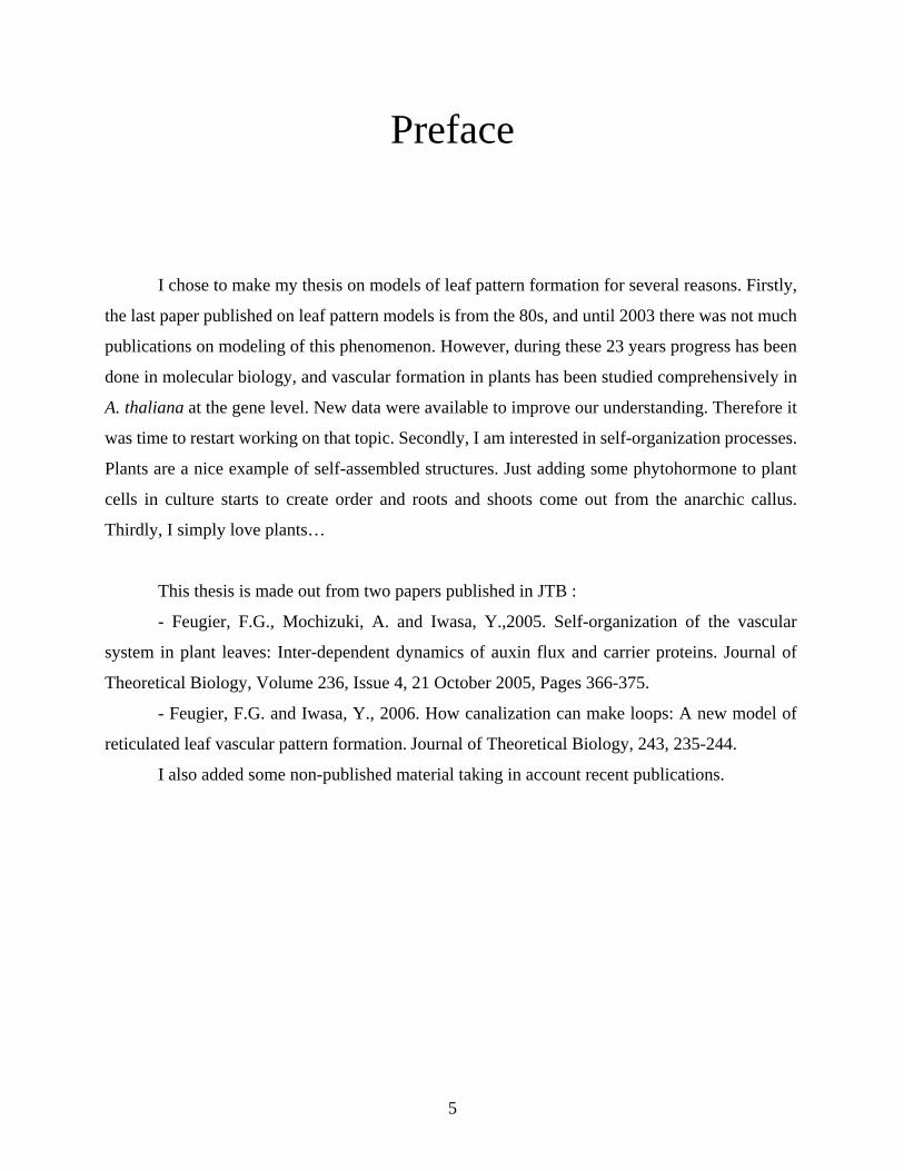