models am-48 and am-48e personal transmission test set instruction...
TRANSCRIPT

Models AM-48 and AM-48EPersonal Transmission
Test Set
INSTRUCTION MANUAL
Models AM-48 and AM-48E
Personal TransmissionTest Set
Instruction Manual
February 4, 2000
Technical Data Subject toChange without Notice
760 Arrow Grand CircleCovina, CA 91722 USA
TEL 626.915.5441FAX 626.915.7181www.ameritec.com
For extra copies ofthis manual, orderPart No. 18-0015 © 2000 Ameritec Corporation
0015-TPG ii
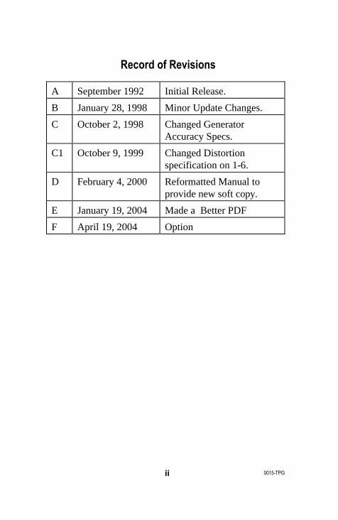
Record of Revisions
A September 1992 Initial Release.
B January 28, 1998 Minor Update Changes.
C October 2, 1998 Changed Generator Accuracy Specs.
C1 October 9, 1999 Changed Distortion specification on 1-6.
D February 4, 2000 Reformatted Manual to provide new soft copy.
E January 19, 2004 Made a Better PDF
F April 19, 2004 Option
AM-48 Test Set (18-0015) Table of Contents
0015-TOC iii
Table of Contents
1. INTRODUCTION ...................................................................................... 1-1
1.1 Manual Overview............................................................................... 1-1
1.2 General Description........................................................................... 1-2
1.3 AM-48 Technical Specifications........................................................ 1-4
1.4 AM-48E Technical Specifications.................................................... 1-11
2. RECEIVING AND UNPACKING.............................................................. 2-1
2.1 Introduction ........................................................................................ 2-1
2.2 Inspection when Received ................................................................ 2-1
2.3 Verification of Contents ..................................................................... 2-1
3. PHYSICAL & FUNCTIONAL DESCRIPTION......................................... 3-1
3.1 Introduction ........................................................................................ 3-1
3.2 General .............................................................................................. 3-1
3.3 Component Location.......................................................................... 3-2
3.4 Connectors and Cables..................................................................... 3-3
3.5 Switches............................................................................................. 3-5
3.6 Keyboard.......................................................................................... 3-14
3.7 Display ............................................................................................. 3-17
3.8 Microphone/Speaker........................................................................ 3-19
3.9 Hand-Held Printer............................................................................ 3-20
3.10 Impedance Adapter ....................................................................... 3-24
4. POWER CONSIDERATIONS.................................................................. 4-1
4.1 General .............................................................................................. 4-1
4.2 Battery Compartment ........................................................................ 4-1
4.3 Battery-Selector Switch ..................................................................... 4-1
4.4 Battery Installation ............................................................................. 4-3
4.5 Battery Information ............................................................................ 4-3
4.6 AC Power........................................................................................... 4-4
4.7 Power On/Off Switch ......................................................................... 4-4
Table of Contents (18-0015) AM-48 Test Set
0015-TOCiv
5. SELF-TEST INSTRUCTIONS.................................................................. 5-1
5.1 General .............................................................................................. 5-1
5.2 Self-Test Setup.................................................................................. 5-1
5.3 Quiet Send Mode............................................................................... 5-4
5.4 Send 1004 Hz.................................................................................... 5-5
5.5 Send PAR (Peak-to-Average Ratio).................................................. 5-7
5.6 Dialing ................................................................................................ 5-8
5.7 Parameter Values for Send Sweep................................................. 5-10
6. CONNECTION AND CONFIGURATION................................................. 6-1
6.1 Introduction ........................................................................................ 6-1
6.2 General .............................................................................................. 6-1
6.3 Connectors and Cables..................................................................... 6-2
6.4 600Ω/900Ω Line Termination Impedances...................................... 6-7
6.5 Impedance Adapter ........................................................................... 6-9
6.6 Configurations.................................................................................. 6-10
7. OPERATING INSTRUCTIONS................................................................ 7-1
7.1 Introduction ........................................................................................ 7-1
7.2 General Instructions and Notes......................................................... 7-3
7.3 General Operating Notes................................................................... 7-3
7.4 Figure Format .................................................................................... 7-4
7.5 General Switch Setup........................................................................ 7-6
7.6 Multiple Use of Keys.......................................................................... 7-8
7.7 Memory .............................................................................................. 7-9
7.8 General Procedure to Set New Parameter Values......................... 7-12
7.9 Send (Generator) Modes and Parameter Settings......................... 7-13
7.10 Types of Send Signals................................................................... 7-13
7.11 Send Quiet.................................................................................... 7-14
7.12 Set Parameters from Quiet Display ............................................. 7-15
7.13 Send Momentary Variable Tones................................................. 7-17
7.14 Send 1004 Hz............................................................................... 7-18
7.15 Send Continuous Variable Tone.................................................. 7-19
AM-48 Test Set (18-0015) Table of Contents
0015-TOC v
7.16 Send Set of Slope Tones ............................................................. 7-19
7.17 Send Variable Sweep................................................................... 7-20
7.18 Send PAR Waveform ................................................................... 7-22
7.19 Send Momentary 2713 Hz Tone.................................................. 7-22
7.20 General Instructions and Notes for MEASURE Modes............... 7-22
7.21 Accuracy of Measurements.......................................................... 7-22
7.22 Absolute and Relative Measurements......................................... 7-23
7.23 Special Measurement Requirements........................................... 7-24
7.24 Timed Tests .................................................................................. 7-26
7.25 MEASURE Modes........................................................................ 7-27
7.26 Measure Level and Frequency..................................................... 7-27
7.27 Measure Noise.............................................................................. 7-28
7.28 Measure PAR................................................................................ 7-29
7.29 Measure Impulse Noise................................................................ 7-29
7.30 Measure Notched Noise............................................................... 7-32
7.31 Measure S/N Ratio ....................................................................... 7-34
7.32 Measure Phase Jitter.................................................................... 7-34
7.33 Measure Amplitude Jitter.............................................................. 7-35
7.34 Measure Transients...................................................................... 7-36
7.35 Miscellaneous Operations............................................................ 7-40
7.36 Store and Recall ........................................................................... 7-40
7.37 Dialing ........................................................................................... 7-43
7.38 Talking........................................................................................... 7-45
7.39 Printing.......................................................................................... 7-45
7.40 Auto Study Result Save................................................................ 7-56
7.41 Impedance Adapter Measurement Corrections........................... 7-56
7.42 Auto Calibrate............................................................................... 7-59
8. EXPLANATION AND APPLICATION OF MEASUREMENTS............... 8-1
8.1 Introduction ........................................................................................ 8-1
8.2 Units of Measurement ....................................................................... 8-1
8.3 Level (Loss or Gain) and Frequency................................................. 8-4
8.4 Idle Channel Noise ............................................................................ 8-4

Table of Contents (18-0015) AM-48 Test Set
0015-TOCvi
8.5 Notched Noise (Noise with Tone) ..................................................... 8-4
8.6 Signal-to-Noise (S/N) Ratio............................................................... 8-5
8.7 P/AR Measurements.......................................................................... 8-6
8.8 Gain Slope ......................................................................................... 8-8
8.9 Idle Channel Impulse Noise .............................................................. 8-9
8.10 Phase Jitter.................................................................................... 8-11
8.11 Amplitude Jitter.............................................................................. 8-11
8.12 Notched Impulse Noise ................................................................. 8-12
8.13 Phase Hits...................................................................................... 8-12
8.14 Gain Hits ........................................................................................ 8-12
8.15 Dropouts......................................................................................... 8-12
9. CIRCUIT DIAGRAMS............................................................................... 9-1
9.1 Introduction ........................................................................................ 9-1
9.2 AM-48 Simplified Block Diagram....................................................... 9-1
9.3 Impedance Adapter Schematic......................................................... 9-3
10. WARRANTY, SERVICE, AND CALIBRATION .................................. 10-1
10.1 Warranty......................................................................................... 10-1
10.2 Service Policy ................................................................................ 10-1
10.3 Calibration Policy........................................................................... 10-1
10.4 Return of Unit................................................................................. 10-2
11. GLOSSARY........................................................................................... 11-1
AM-48 Test Set (18-0015) Table of Contents
0015-TOC vii
List of Figures
Figure 3-1. AM-48 Location of Components................................................ 3-3
Figure 3-2. AM-48 Connectors..................................................................... 3-4
Figure 3-3. Standard AM-48 Cables ............................................................ 3-4
Figure 3-4. Optional AM-48 Cables.............................................................. 3-5
Figure 3-5. AM-48 Switch Identification Numbers ....................................... 3-6
Figure 3-6. AM-48 Keyboard Identification Numbers ................................ 3-15
Figure 3-7. AM-48 Liquid Crystal Display .................................................. 3-18
Figure 3-8. Hand-Held Printer, External View............................................ 3-22
Figure 3-9. Hand-Held Printer, Internal View............................................. 3-23
Figure 3-10. Impedance Adapter................................................................ 3-24
Figure 4-1. Battery Installation and Selector Switch.................................... 4-2
Figure 5-1. AM-48 Setup for Self-Test (Looped Back) ................................ 5-2
Figure 5-2. General Switch Setup for Self Test ........................................... 5-3
Figure 5-3. Quiet Send Mode Self Test........................................................ 5-4
Figure 5-4. Send 1004 Hz Self Test, Switch Settings.................................. 5-6
Figure 5-5. Send 1004 Hz Self Test, Displays............................................. 5-7
Figure 5-6. Send PAR (Peak-to-Average Ratio).......................................... 5-8
Figure 5-7. Dialing....................................................................................... 5-10
Figure 5-8. Default Parameter Settings for SWEEP Send Mode.............. 5-14
Figure 6-1. 2-Wire AM-48 Line Connections................................................ 6-3
Figure 6-2. 4-Wire AM-48 Line Connections................................................ 6-4
Figure 6-3. AM-47 Hand-Held Printer Connection with AC Power.............. 6-5
Figure 6-4. 4-Wire End-to-End Testing...................................................... 6-11
Figure 6-5. 4-Wire Testing with Responder ............................................... 6-13
Figure 6-6. 2-Wire Network Testing with Responders............................... 6-14
Figure 7-1. Parameter Settings from QUIET SEND Display..................... 7-15
Figure 7-2. Parameter Settings from 1004 Hz and VAR Tone Displays ...7-18
Table of Contents (18-0015) AM-48 Test Set
0015-TOCviii
Figure 7-3. Parameter Settings from 3-TONE Slope andPAR SEND Displays......................................................... 7-20
Figure 7-4. Parameter Settings from SWEEP SEND Display................... 7-21
Figure 7-5. L/F, NOISE, and PAR MEASURE Displays............................ 7-28
Figure 7-6. IMPLS MEASURE Displays..................................................... 7-32
Figure 7-7. Notched NOISE and S/N Ratio MEASURE Displays ............. 7-33
Figure 7-8. Phase JTR and Amplitude JTR MEASURE Displays............. 7-35
Figure 7-9. TRANS MEASURE Displays..........................................7-39, 7-40
Figure 7-10. Recall and Store Operations ................................................. 7-42
Figure 7-11. SEND Printouts...................................................................... 7-52
Figure 7-12. MEASURE Printouts, Absolute Measure Mode.................... 7-54
Figure 7-13. MEASURE Printouts, Relative Measure Mode..................... 7-55
Figure 7-14. Impedance Adapter Correction Value Memory Aid............... 7-58
Figure 7-15. AM-48 Auto Calibrate Prompts.............................................. 7-60
Figure 8-1. Level and Noise Units of Measurement .................................... 8-2
Figure 8-2. Impulse Noise Thresholds and Blanking Intervals.................. 8-10
Figure 9-1. Simplified Block Diagram of the AM-48..................................... 9-2
Figure 9-2. Schematic Diagram of the Impedance Adapter........................ 9-4
AM-48 Test Set (18-0015) Table of Contents
0015-TOC ix
List of Tables
Table 1-1. AM-48 General Technical Specifications ................................... 1-5
Table 1-2. AM-48 Generator (Send) Technical Specifications.................... 1-6
Table 1-3. AM-48 Receiver (Measure) Technical Specifications................ 1-8
Table 1-4. AM-48 Power/Physical Technical Specifications ..................... 1-11
Table 2-1. AM-48 Standard Equipment ....................................................... 2-2
Table 2-2. AM-48 Optional Equipment ........................................................ 2-2
Table 3-1. Front Panel/Switches Color Coding............................................ 3-2
Table 3-2. AM-48 SEND, MEASURE, and FILTER Menus....................... 3-19
Table 3-3. AM-47 Hand-Held Printer Technical Specifications................. 3-21
Table 7-1. Setup Requirements for Different Keyboard Applications ......... 7-8
Table 7-2. Steps for Up and Down Arrow Keys........................................... 7-9
Table 7-3. User-Programmable Parameter Values Stored in Memory..... 7-11
Table 7-4. Acceptable Holding Tone Ranges............................................ 7-25
Table 7-5. Special Measurement Requirements........................................ 7-26
Table 7-6. Setup Requirements for Dialing................................................ 7-44
Table 7-7. MF and DTMF Tone Pairs......................................................... 7-44
Table 7-8. Impedance Adapter Correction Values..................................... 7-57
Table 8-1. P/AR Requirements of Telephone Lines.................................... 8-6

AM-48 Test Set (18-0015) Introduction
0015-S01 1-1
1. INTRODUCTION
1.1 Manual OverviewThis instruction manual describes Ameritec Corporation’s AM-48
and AM-48E Personal Transmission Test Sets.
Note: Throughout this manual, all references to the "AM-48" also
apply to the "AM-48E", unless otherwise noted. See ¶1.4
for a summary of the differences between the AM-48 and
the AM-48E.
The other paragraphs in this Introduction section are:
1.2 General Description
1.3 AM-48 Technical Specifications
1.4 AM-48E Technical Specifications
The balance of the manual is divided into the following sections:
2. Receiving and Unpacking
3. Physical and Functional Description
4. Power Considerations
5. Self-Test Instructions
6. Connection and Configuration
7. Operating Instructions
8. Explanation and Application of Measurements
9. Circuit Diagrams
10. Warranty, Service, and Calibration
11. Glossary
Index
Introduction (18-0015) AM-48 Test Set
0015-S011-2
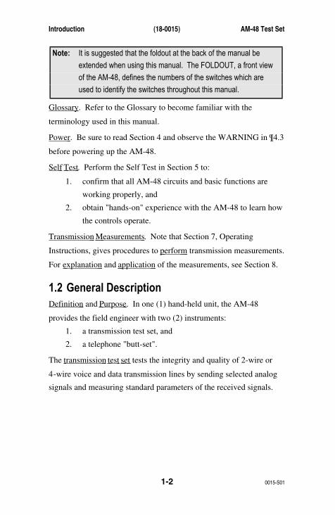
Note: It is suggested that the foldout at the back of the manual be
extended when using this manual. The FOLDOUT, a front view
of the AM-48, defines the numbers of the switches which are
used to identify the switches throughout this manual.
Glossary . Refer to the Glossary to become familiar with the
terminology used in this manual.
Power . Be sure to read Section 4 and observe the WARNING in ¶4.3
before powering up the AM-48.
Self Test . Perform the Self Test in Section 5 to:
1. confirm that all AM-48 circuits and basic functions are
working properly, and
2. obtain "hands-on" experience with the AM-48 to learn how
the controls operate.
Transmission Measurements . Note that Section 7, Operating
Instructions, gives procedures to perform transmission measurements.
For explanation and application of the measurements, see Section 8.
1.2 General DescriptionDefinition and Purpose . In one (1) hand-held unit, the AM-48
provides the field engineer with two (2) instruments:
1. a transmission test set, and
2. a telephone "butt-set".
The transmission test set tests the integrity and quality of 2-wire or
4-wire voice and data transmission lines by sending selected analog
signals and measuring standard parameters of the received signals.

AM-48 Test Set (18-0015) Introduction
0015-S01 1-3
The telephone "butt set" enables the field engineer to dial up and
speak back-and-forth with a field engineer at the far end of the
system. The compact and light-weight AM-48 eliminates the need to
carry multiple, bulky test sets.
Functional Overview
AM-48 can send:
• any frequency from 200 Hz to 20 kHz @ -50 to +10 dBm
• continuous 3-tone slope (404, 1004, 2804 Hz)
• continuous, user-defined, sweep tones
• fixed 1004 Hz
• P/AR waveform
• momentary 2713 Hz for WECO 829 loopback
AM-48 can measure:
• level, -65 to +10.9 dBm (absolute or relative)
• frequency, 0 to 19,999 Hz
• idle channel noise
• noise with tone
• three-level impulse noise
• phase jitter
• gain jitter
• transients (dropouts, phase and gain hits, impulse noise)
• signal-to-noise (S/N) ratio
• peak-to-average ratio (P/AR)
Noise filters provided (each with optional 1010 Hz notch)::
• C-Message (Psophometric for AM-48E)
• 3 kHz
• 15 kHz
• Program (Sound-weighted for AM-48E)

Introduction (18-0015) AM-48 Test Set
0015-S011-4
Other features:
• High impedance bridge, 600 or 900 Ohm termination
• Display prompts help in set-up and testing sequences
• On-board memory can store & recall up to 10 user-defined
test set-ups
• Dials: pulse, DTMF, and MF
• Talk/Listen capability
• Printer interface for hard copy of set-up and test results
• Battery life: Alkaline, 6 to 7 hours; NiCad, 3 to 4 hours
• NiCad batteries can be recharged without removing them
from the unit
Testing Configurations: (For details, see ¶6.6)
There are three (3) basic AM-48 configurations used to test
2-wire/4-wire telephone/data communication lines:
1. End-to-end -- requiring two (2) AM-48 units
2. Loopback
3. Testing with responders
1.3 AM-48 Technical SpecificationsAM-48 technical specifications are presented in four (4) parts:
1. General (Table 1-1)
2. Generator (Send) (Table 1-2)
3. Receiver (Measure) (Table 1-3)
4. Power/Physical (Table 1-4)

AM-48 Test Set (18-0015) Introduction
0015-S01 1-5
Table 1-1. AM-48 General Technical Specifications
Characteristic Specification
Measurements
Level -65 to +10.9 dBm
Frequency 0 to 19,999 Hz
Noise 10 to 99 dBrn
Notched Noise 10 to 99 dBrn
Signal to Noise 0 to 60 dB
P/AR 0 to 120
Amplitude Jitter 0.0 to 25.0%
Phase Jitter 0.0 to 25.0 degrees
3-Level Impulse Noise Counts from 0 to 9999
Transient Measurements
Dropouts 0 to 9999
Gain Hits 0 to 9999
Phase Hits 0 to 9999
3-Level Impulse Noise Counts from 0 to 9999
Dial Built-in 16 button keypad for dial pulse, DTMF (TouchTone), or MF dialing.
Talk Built-in microphone and speaker with push-to-talkoperation on both 2-wire and 4-wire lines. Earphonejack for optional earphone.
Holding A single line holding circuit is provided for 2-wireoperation, or the send pair of 4-wire circuits. Itelectronically simulates a holding coil with a DCresistance of approximately 200 ohms. The ACimpedance is high enough to give no more than 0.2 dBloss at 600 ohm impedance.
Impedances 600 and 900 ohm.
Balance > 60 dB below 4 kHz, decreasing 6 dB.octaveabove 5 kHz.
Return loss > 30 dB 200-5000 Hz, > 15 dB 5-20 kHz.
DC blocking - 150 Volts.
Bridging impedance > 25 kohms.
Introduction (18-0015) AM-48 Test Set
0015-S011-6
Characteristic Specification
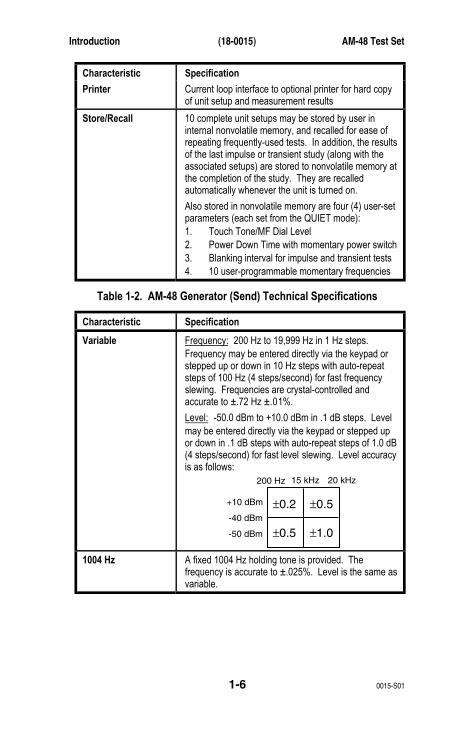
Printer Current loop interface to optional printer for hard copyof unit setup and measurement results
Store/Recall 10 complete unit setups may be stored by user ininternal nonvolatile memory, and recalled for ease ofrepeating frequently-used tests. In addition, the resultsof the last impulse or transient study (along with theassociated setups) are stored to nonvolatile memory atthe completion of the study. They are recalledautomatically whenever the unit is turned on.
Also stored in nonvolatile memory are four (4) user-setparameters (each set from the QUIET mode):1. Touch Tone/MF Dial Level2. Power Down Time with momentary power switch3. Blanking interval for impulse and transient tests4. 10 user-programmable momentary frequencies
Table 1-2. AM-48 Generator (Send) Technical Specifications
Characteristic Specification
Variable Frequency: 200 Hz to 19,999 Hz in 1 Hz steps.Frequency may be entered directly via the keypad orstepped up or down in 10 Hz steps with auto-repeatsteps of 100 Hz (4 steps/second) for fast frequencyslewing. Frequencies are crystal-controlled andaccurate to ±.72 Hz ±.01%.
Level: -50.0 dBm to +10.0 dBm in .1 dB steps. Levelmay be entered directly via the keypad or stepped upor down in .1 dB steps with auto-repeat steps of 1.0 dB(4 steps/second) for fast level slewing. Level accuracyis as follows:
±0.2 ±0.5
±0.5 ±1.0
200 Hz
+10 dBm
-40 dBm
-50 dBm
15 kHz 20 kHz
1004 Hz A fixed 1004 Hz holding tone is provided. Thefrequency is accurate to ±.025%. Level is the same asvariable.

AM-48 Test Set (18-0015) Introduction
0015-S01 1-7
Characteristic Specification
3-Tone A three-tone slope frequency mode is provided, whichcycles continuously between 404 Hz, 1004 Hz, and2804 Hz, giving 5 seconds of each tone. Frequencyaccuracy is the same as variable. Level is the sameas variable.
Sweep A programmable frequency sweep generator isprovided. It generates tones continuously from a user-specified START frequency (200 Hz to 19,999 Hz) to auser-specified STOP frequency (200 Hz to 19,999 Hz),at a user-specified frequency STEP interval (1 Hz to19,999 Hz), and at a user-specified step RATE (0.1second to 19,999 seconds/frequency). Frequencyaccuracy is the same as variable. Level is the sameas variable.
PAR A PAR waveform generator is provided, whichgenerates the 16 simultaneous frequency PARwaveform per Bell 41009 specifications. The levelmay be set from -40.0 dBm to 0.0 dBm, with 0.1 dBmresolution. Level accuracy is ±0.5 dBm.
Quiet In quiet mode, the line is terminated with a passiveresistance equal to the line impedance. Also, when inQuiet, one of 10 user-programmable tones may bemomentarily applied to the line by depressing the (0)thru (9) keys.
Programmable from this mode are (1) Touch Tone diallevel (-50.0 to 7 dBm), (2) Power down Time Off (1 to255 minutes), (3) Impulse and Transient test BlankingInterval (1 to 255 ms), and (4) 10 user-programmabletones for later instant recall.
Aux Tone A momentary pushbutton is provided for thegeneration of an auxiliary tone (2713 Hz), used toactivate remote 829-type loopback devices.
SF Skip A Signaling Frequency (SF) Skip mode prevents thegeneration of tones between 2450 Hz and 2750 Hz invariable or sweep modes.
Distortion Total distortion is < -50 dB @ 1004 fixed tone and< -40 dB @ any other frequency.
Introduction (18-0015) AM-48 Test Set
0015-S011-8
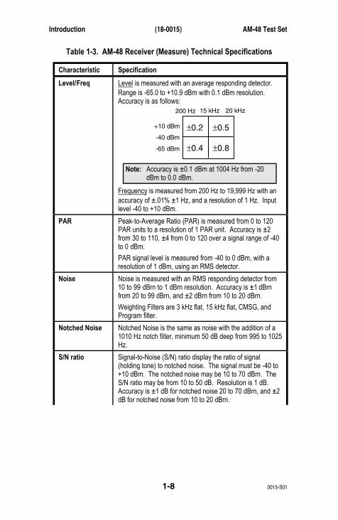
Table 1-3. AM-48 Receiver (Measure) Technical Specifications
Characteristic Specification
Level/Freq Level is measured with an average responding detector.Range is -65.0 to +10.9 dBm with 0.1 dBm resolution.Accuracy is as follows:
±0.2 ±0.5
±0.4 ±0.8
200 Hz
+10 dBm
-40 dBm
-65 dBm
15 kHz 20 kHz
Note: Accuracy is ±0.1 dBm at 1004 Hz from -20dBm to 0.0 dBm.
Frequency is measured from 200 Hz to 19,999 Hz with anaccuracy of ±.01% ±1 Hz, and a resolution of 1 Hz. Inputlevel -40 to +10 dBm.
PAR Peak-to-Average Ratio (PAR) is measured from 0 to 120PAR units to a resolution of 1 PAR unit. Accuracy is ±2from 30 to 110, ±4 from 0 to 120 over a signal range of -40to 0 dBm.
PAR signal level is measured from -40 to 0 dBm, with aresolution of 1 dBm, using an RMS detector.
Noise Noise is measured with an RMS responding detector from10 to 99 dBrn to 1 dBrn resolution. Accuracy is ±1 dBrnfrom 20 to 99 dBrn, and ±2 dBrn from 10 to 20 dBrn.
Weighting Filters are 3 kHz flat, 15 kHz flat, CMSG, andProgram filter.
Notched Noise Notched Noise is the same as noise with the addition of a1010 Hz notch filter, minimum 50 dB deep from 995 to 1025Hz.
S/N ratio Signal-to-Noise (S/N) ratio display the ratio of signal(holding tone) to notched noise. The signal must be -40 to+10 dBm. The notched noise may be 10 to 70 dBrn. TheS/N ratio may be from 10 to 50 dB. Resolution is 1 dB.Accuracy is ±1 dB for notched noise 20 to 70 dBrn, and ±2dB for notched noise from 10 to 20 dBrn.

AM-48 Test Set (18-0015) Introduction
0015-S01 1-9
Characteristic Specification
Amplitude Jitter Displays the incidental amplitude modulation of a holdingtone. The holding tone must be -40 to +10 dBm, 990 to1030 Hz. Amplitude jitter is displayed from 0.0 to 25.0%with a resolution of .1% and an accuracy of ±.2%, ±5% ofreading.
Weighting filter selection: 20-300 Hz or 4-300 Hz.
Phase Jitter Displays the incidental phase modulation of a holding tone.The holding tone must be -40 to +10 dBm, 990 to 1030 Hz.Phase jitter is displayed in degrees from 0.0 to 25.0degrees with a resolution of .1 degree and an accuracy of±.2 degree, ±5% of reading.
Weighting filter selection: 20-300 Hz or 4-300 Hz.
Impulse Noise Three (3) noise thresholds are established: Low, Middle,and High levels, with an equal interval between them calledthe Delta. The maximum High threshold is 105 dBrn for600 ohm impedance (or 104 dBrn for 900 ohm). Theminimum Low threshold is 30 dBrn. Delta can be 2, 3, 4, or6 dB. Threshold accuracy: ±1 dB. A user-selectedblanking interval of 1 to 255 ms for each threshold, blocksfurther counting of impulses at that threshold.
The study duration timer may be set from .1 minute to1999.9 minutes in .1 minute steps, or continuous. Eachthreshold has a count capacity of 0-9999. Weighting filterssame as noise.
Transients Counts dropouts, gain hits, phase hits, and 3-level impulsenoise with tone. Holding tone must be -40 to +10 dBm, 995to 1025 Hz
Dropout threshold is -12 dB from the initial level of theholding tone. A dropout will be counted if the holding tonedrops below the threshold for at least 4 ms ±.5 ms.Counting of dropouts, gain hits, phase hits, and impulses isinhibited for a blanking interval which lasts until 1 secondafter the holding tone is restored to a level above thedropout threshold.

Introduction (18-0015) AM-48 Test Set
0015-S011-10
Characteristic Specification
Transients(cont.)
Gain hit threshold can be 2, 3, 4, or 6 dB. A gain hit will becounted if the level of the holding tone changes up or downby more than the threshold for at least 4 ms ±.5 ms. Ablanking interval, that is user-set from 1 to 255 ms, blocksfurther counting of gain hits.
Phase hit threshold can be 5 to 45 degrees in 1 degreesteps, with an accuracy of ±.5 degrees ±10% of the setting.A phase hit will be counted if the phase of the holding tonechanges by more than the threshold fro at least 4 ms ±.5ms. A blanking interval, that is user-set from 1 to 255 ms,blocks further counting of phase hits.
The three-level impulse noise low threshold can be set from30 to 110 dBrn with threshold differences of 2, 3, 4, or 6 dB.Threshold accuracy: ±1 dB. An independent blankinginterval for each threshold, user-set from 1 to 255 ms,blocks further counting of impulses at that threshold.
The study duration timer may be set from .1 minute to1999.9 minutes in .1 minute steps, or set to 0 for acontinuous study.
Each transient has a count capacity of 0-9999.
Filters same as noise.
Damping A damp mode reduces the display update rate fromapproximately 4 times/second to approximately 2times/second for reading widely fluctuating measurements.
The same switch, when in <DAMP> position, also changesthe monitoring point of the receive (RCV) monitor speakerto the output of the auto-range amplifier (significantlyincreasing the speaker level).
Term/Bridge When in terminate, the receiver terminates the line in theselected impedance. When in bridge, the line is bridged bya high impedance, causing no more than .2 dB loss on a600 ohm line.
AM-48 Test Set (18-0015) Introduction
0015-S01 1-11
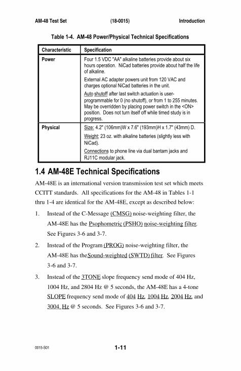
Table 1-4. AM-48 Power/Physical Technical Specifications
Characteristic Specification
Power Four 1.5 VDC "AA" alkaline batteries provide about sixhours operation. NiCad batteries provide about half the lifeof alkaline.
External AC adapter powers unit from 120 VAC andcharges optional NiCad batteries in the unit.
Auto shutoff after last switch actuation is user-programmable for 0 (no shutoff), or from 1 to 255 minutes.May be overridden by placing power switch in the <ON>position. Does not turn itself off while timed study is inprogress.
Physical Size: 4.2" (106mm)W x 7.6" (193mm)H x 1.7" (43mm) D.
Weight: 23 oz. with alkaline batteries (slightly less withNiCad).
Connections to phone line via dual bantam jacks andRJ11C modular jack.
1.4 AM-48E Technical SpecificationsAM-48E is an international version transmission test set which meets
CCITT standards. All specifications for the AM-48 in Tables 1-1
thru 1-4 are identical for the AM-48E, except as described below:
1. Instead of the C-Message (CMSG) noise-weighting filter, the
AM-48E has the Psophometric (PSHO) noise-weighting filter .
See Figures 3-6 and 3-7.
2. Instead of the Program (PROG) noise-weighting filter, the
AM-48E has the Sound-weighted (SWTD) filter . See Figures
3-6 and 3-7.
3. Instead of the 3TONE slope frequency send mode of 404 Hz,
1004 Hz, and 2804 Hz @ 5 seconds, the AM-48E has a 4-tone
SLOPE frequency send mode of 404 Hz , 1004 Hz , 2004 Hz , and
3004 Hz @ 5 seconds. See Figures 3-6 and 3-7.
Introduction (18-0015) AM-48 Test Set
0015-S011-12
4. Instead of Signal Frequency (SF) Skip 2450 Hz to 2750 Hz, the
AM-48E has SF SKIP from 2130 Hz to 2430 Hz .
5. On all noise displays, instead of units of dBrn , the AM-48E
displays the noise in units of dBm . See ¶8.2 and Figure 8-1 for
definitions and corresponding values of dBrn and dBm units.

AM-48 Test Set (18-0015) Receiving and Unpacking
0015-S02 2-1
2. RECEIVING AND UNPACKING
2.1 IntroductionThis section covers procedures to follow when the AM-48 is first
received in its shipping container:
2.2 Inspection when Received
2.3 Verification of Contents
2.2 Inspection when ReceivedThe AM-48 was thoroughly tested and carefully packed before
shipment, and was in good condition when turned over to the carrier
for transport.
The name of the carrier will be noted on the packing slip which
accompanied the shipment.
Upon receipt, thoroughly inspect the outside of the shipping container
for damage. If the container is damaged, and the AM-48 is found to
be damaged or non-operational, immediately contact the carrier and
submit a claim for damages.
Note: To test if the unit is operational, see Section 4 for Power
Considerations and Section 5 for Self-Test Instructions.
2.3 Verification of ContentsAfter opening and unpacking, use the following equipment lists to
verify that all ordered items have been received. Note that some
items are standard and always included; other items are optional, and
only shipped when specially ordered.

Receiving and Unpacking (18-0015) AM-48 Test Set
0015-S02 2-2
Table 2-1. AM-48 Standard Equipment
Amount Part Number Description
1 AM-48 unit
4 24-0006 AA-size 1.5 VDC alkaline batteries
1 48-0049 Modular input cord with minigator clips
1 82-0005 Earphone
1 70-0029 AC Adapter
1 18-0015 AM-48/AM-48E Instruction Manual
1 87-0009 AC Adapter
Table 2-2. AM-48 Optional Equipment
Amount Part Number Description
1 24-0005 Impedance Adapter (1200, 150, 135, 75 ohms)
4 24-0006 AA-size alkaline batteries (replacement set)
4 24-0007 AA-size NiCad (rechargeable) batteries
1 AM-47 Hand-held printer - includes roll of paper, ribbon cartridge, and 48-0079 Printer Cable.
1 26-0014 roll of paper for Hand-held printer
1 26-0015 ribbon cartridge for Hand-held printer
1 48-0047 Bantam (M) to Bantam (M) Cable (6') (two required for 4-wire operation)
1 48-0048 Bantam (M) to 310 (M) Cable (6') (two required for 4-wire operation)
1 48-0049 Modular to Minigator Cable (7')
1 48-0062 Bantam (M) to Minigator Cable (6') (two required for 4-wire operation)
1 48-0078 Printer Cable for use with an EIA printer
1 48-0079 Printer Cable for use with Ameritec Hand-held printer.
1 87-0016 AM4 Soft Carrying Case
See Figure 3-3 for illustrations of the cables listed in Tables 2-1 and
2-2.
AM-48 Test Set (18-0015) Unit Description
0015-S03 3-1
3. PHYSICAL & FUNCTIONAL DESCRIPTION
3.1 IntroductionThis section illustrates and explains the components of the AM-48.
Also described are the Hand-held Printer and the Impedance Adapter.
This section is divided into the following paragraphs:
3.2 General
3.3 Component Location
3.4 Connectors and Cables
3.5 Switches
3.6 Keyboard
3.7 Display
3.8 Microphone/Speaker
3.9 Hand-held Printer
3.10 Impedance Adapater
See ¶4.2 for the description of the battery compartment.
3.2 GeneralThe AM-48 weighs 23 ounces (with batteries) and measures 4.2" x
7.6" x 1.7" (106mm x 193mm x 43mm).
All electronic components are mounted on three (3) interlocking
printed circuit boards, housed in a high-impact injection-molded ABS
plastic case. The case is factory-sealed, since there are no user-
serviceable parts inside.
To stand or hang the AM-48, use the hinged wire bail at the top of the
case. Lift the bail until it snaps into the detent of the desired position.
The front panel and switches are color-coded to tie together
associated functions.
Unit Description (18-0015) AM-48 Test Set
0015-S033-2
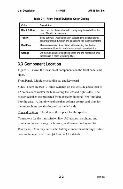
Table 3-1. Front Panel/Switches Color Coding
Color Description
Black & Blue Line controls. Associated with configuring the AM-48 for thetype of line to be measured.
Yellow Send controls. Associated with selecting the desired signalgenerator (send) function and controlling the signal generator.
Red/Pink Measure controls. Associated with selecting the desiredmeasurement function and measurement characteristics.
Orange On menus: all noise-weighting filters and the measurementsthat require a noise-weighting filter.
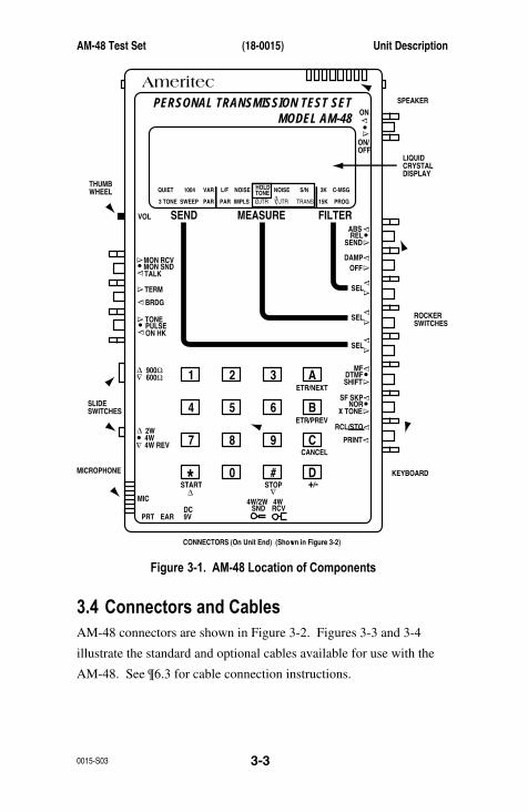
3.3 Component LocationFigure 3-1 shows the location of components on the front panel and
sides.
Front Panel . Liquid crystal display and keyboard.
Sides . There are two (2) slide switches on the left side and a total of
12 color-coded rocker switches along the left and right sides. The
rocker switches are protected from abuse by integral "ribs" molded
into the case. A thumb wheel speaker volume control and slots for
the microphone are also located on the left side.
Top and Bottom . The slots at the top are for the speaker.
Connectors for the transmission line, AC adapter, earphone, and
printer are located along the bottom, as illustrated in Figure 3-2.
Rear Panel . You may access the battery compartment through a slide
door in the rear panel. See ¶4.2 and 4.3 for details.
AM-48 Test Set (18-0015) Unit Description
0015-S03 3-3
AmeritecPERSONAL TRANSMISSION TEST SET
MODEL AM-48
SEND MEASURE FILTER
ON
ABSREL
SEND
ON/OFF
∇
∇
∇
DAMP
∇
∇
OFF
SEL
900Ω600Ω
∇
∇
∇
SEL
∇
∇
SEL
∇
∇
3K C-MSG
15K PROG
QUIET 1004 VAR
PAR
L/F
PAR3 TONE SWEEP
NOISE NOISE S/NHOLDTONE
IMPLS ØJTR JTR TRANS∇∆
•
•
MON RCV
SPEAKER
LIQUIDCRYSTALDISPLAY
ROCKERSWITCHES
THUMBWHEEL
SLIDESWITCHES
KEYBOARDMICROPHONE
CONNECTORS (On Unit End) (Shown in Figure 3-2)
MON SNDTALK
∇
TERM∇
BRDG
∇∇•
4W•
TONEPULSEON HK
∇
∇•
MFDTMFSHIFT
ETR/NEXT
ETR/PREV
CANCEL
STOPSTART
4W/2WSND
4WRCV
+/-
∇
∇
∇
∇
∇2W
4W REV
MIC
VOL
PRT EARDC9V
∇
∇
∇•
SF SKPNOR
X TONE
∇
RCL/STO
∇
∇
•
∇
21 A3
54 B6
87 C9
0* D#
Figure 3-1. AM-48 Location of Components
3.4 Connectors and CablesAM-48 connectors are shown in Figure 3-2. Figures 3-3 and 3-4
illustrate the standard and optional cables available for use with the
AM-48. See ¶6.3 for cable connection instructions.

Unit Description (18-0015) AM-48 Test Set
0015-S033-4
Note: The AM-47 Hand-held Printer includes its own cable, P/N
48-0079. The Printer Cable P/N 48-0078 is for connection
to the RS-232 port (25-pin female) of most other serial EIA
printers..
PRINTER JACK<PRT>
EARPHONE JACK<EAR>
AC ADAPTERPLUG <DC 9V>
RJ11 MODULARJACK
4-WIRE RECEIVEBANTAM JACK
4-WIRE SEND,2-WIRE
BANTAM JACK
Figure 3-2. AM-48 Connectors
YELLOW
GREEN
RED
BLACK
RJ-11 CABLE 48-0049, 7 Ft
2.5 mm JACK AC ADAPTER 70-0029, 6 Ft
EARPHONE 82-0005, 3 Ft
Figure 3-3. Standard AM-48 Cables

AM-48 Test Set (18-0015) Unit Description
0015-S03 3-5
GREEN
RED
R
T
SBLACK
CABLE 48-0062, 6 FtBANTAM PLUG
CABLE 48-0047, 6 FtBANTAM PLUG BANTAM PLUG
CABLE 48-0048, 6 FtBANTAM PLUG 310 PLUG
2.5 mm JACK
2.5 mm PLUG
4-WIDEMODULAR
PRINTER CABLE 48-0079, 6 Ft
2.5 mm PLUG DB25 PLUGPRINTER CABLE 48-0078, 6 Ft
Figure 3-4. Optional AM-48 Cables
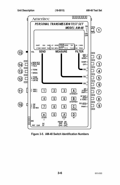
3.5 SwitchesFigure 3-5 shows the location of the AM-48 switches. The functional
descriptions of the switches in this paragraph follows the same
numbering scheme as Figure 3-5.
Note: Throughout this manual, a switch position indicated on the
front panel is referred to with angular brackets, <>. For
example, <ABS> refers to the absolute measurement position
of Switch 2.
Switches are referred to by number throughout this manual.
See Figure 3-5 for ease of reference of switch numbers.
Unit Description (18-0015) AM-48 Test Set
0015-S033-6
AmeritecPERSONAL TRANSMISSION TEST SET
MODEL AM-48
SEND MEASURE FILTER
ON
ABSREL
SEND
ON/OFF
∇
∇
∇
DAMP
∇
∇
OFF
SEL
900Ω600Ω
∇
∇
∇
SEL
∇
∇SEL
∇
∇
3K C-MSG
15K PROG
QUIET 1004 VAR
PAR
L/F
PAR3 TONE SWEEP
NOISE NOISE S/NHOLDTONE
IMPLS ØJTR JTR TRANS∇∆
•
•
MON RCVMON SNDTALK
∇
TERM∇
BRDG
∇∇•
4W•
TONEPULSEON HK
∇
∇•
MFDTMFSHIFT
ETR/NEXT
ETR/PREV
CANCEL
STOPSTART
4W/2WSND
4WRCV
+/-
∇
∇
∇
∇
∇
2W
4W REV
MIC
VOL
PRT EARDC9V
∇
∇
∇
•
SF SKPNOR
X TONE
∇
RCL/STO
∇
∇
•
∇
21 A3
54 B6
87 C9
0* D#
15
14
13
12
11
1
2
3
8
9
4
5
6
7
10
Figure 3-5. AM-48 Switch Identification Numbers
AM-48 Test Set (18-0015) Unit Description
0015-S03 3-7
There are three (3) types of switches:
Thumb Wheel : "Switch" 15 is the only thumb wheel. It is a
volume control. Push up (toward the front panel) on <VOL> to
increase the volume of the monitor speaker. Push down on
<VOL> to decrease the monitor speaker volume.
Slide Switches : Switches 10 and 11 are slide switches. Push
these switches toward the top or the bottom in the direction
indicated by the arrows on the front panel to select the desired
line parameter.
Rocker Switches : The other 12 switches are rocker switches.
The action of these switches is rather like a rocking chair. Rock
the appropriate switch toward or away from the front panel as
indicated by the arrows to activate the desired function. There
are various combinations between toggle and/or momentary
switching action as explained in the functional descriptions
which follow (reference Figure 3-5).
1 Power . Combination toggle and momentary rocker switch.
• Set to <ON> position for power to be on continuously.
• To allow the AM-48 to power down by itself, turn the
power on by momentarily pressing the switch toward
the <ON/OFF> position. The power will shut off
automatically after the TIME OFF setting, if the unit is
left unattended. (See ¶7.12 for instructions to set the
time).
• To turn the power off, momentarily press the switch
toward the <ON/OFF> position.
Unit Description (18-0015) AM-48 Test Set
0015-S033-8
2 Display Select . Three-position toggle switch. This
determines what is being viewed on the display.
• Set <ABS> to view MEASUREMENT mode in absolute
reference.
• Set <REL> to view MEASUREMENT mode in relative
reference.
• Set <SEND> to view the SEND mode.
See ¶7.22 and 8.2 for explanation of absolute and relative
measurements.
3 Two-position toggle switch. This switch has a dual
function:
A. Controls the display damping. <DAMP> gives a
display update of two times per second (used with
widely fluctuating signals to update the display more
often for better sampling of the measurement).
<OFF> gives a display update of four times per
second.
B. Controls the monitoring point of the receive monitor
speaker (<MON RCV> position of Switch 14).
<DAMP> gives a monitoring point at the output of the
auto-range amplifier, significantly increasing the
spaeker level.. See Figure 9-1 for a block diagram
showing how this switch interacts with Switch 14.
AM-48 Test Set (18-0015) Unit Description
0015-S03 3-9
4 Filter Select . Dual momentary switch. Rock up or down
to move FILTER menu cursor left or right to select desired
noise-weighting filter. See Table 7-5 for a list of
measurements that require a noise-weighting filter. See
Figure 3-8 for the FILTER menu.
5 Measure Select . Dual momentary switch. Rock up or
down to move MEASURE menu cursor left or right to
select desired measure mode. See Figure 3-8 for the
MEASURE menu.
6 Send Select . Dual momentary switch. Rock up or down
to move SEND menu cursor left or right to select desired
send (generator) mode. See Figure 3-8 for the SEND
menu.
7 Three-position toggle switch. See Table 7-6 for
interaction of this switch with Switch 12 for dialing.
• Set <MF> to dial multi-frequency tones from the
keyboard.
• Set <DTMF> to dial DTMF (Touch Tone) from the
keyboard.
• Set <SHIFT> to enable the auxiliary functions on the
keyboard. See ¶3.6 for details.
Unit Description (18-0015) AM-48 Test Set
0015-S033-10
8 Two-position toggle plus momentary switch.
• Set <SF SKP> to skip the signaling frequency band of
2450 Hz to 2750 Hz (2130 Hz to 2430 Hz for
AM-48E), avoiding the accidental transmission of
signaling frequencies.
• Set <NOR> to allow the internal signal generator to be
stepped through all frequencies within its range while
in the SWEEP and VAR SEND modes.
• Press <X TONE> to momentarily send a 2713 Hz tone,
overriding the internal signal generator. This feature
is useful for actuating loopback devices. See ¶6.6
under " Loopback Testing " for the procedure to use the
Western Electric Model 829 loopback device.
9 Dual momentary switch.
• Press <RCL/STO> to recall and/or store up to 10 test
setups. See ¶7.36 for details.
• Press <PRINT> to send unit setup and measurement
results to the printer port, <PRT>. See ¶3.9 and 7.39
for details.
10 Three-position slide switch. See Figure 6-1 and 6-2 for
2-wire and 4-wire line connections associted with this
switch.
• Set <2W> to connect the internal measurement
circuitry and signal generator across the 2-wire line at
the <SND> jack. The signal generator source
impedance of 600 or 900 ohms terminates the line in
all signal generator modes except QUIET.
AM-48 Test Set (18-0015) Unit Description
0015-S03 3-11
In QUIET mode, the line will be terminated only if
Switch 13 is set to <TERM>. See Figure 6-1.
Note: The <RCV> jack is not used when connecting
to 2-wire circuits.
• Set <4W> to connect the internal measurement
circuitry to the <RCV> pair, and the internal signal
generator to the <SND> pair. See the upper half of
Figure 6-2.
• Set <4W REV> to reverse the send and receive pairs.
See the lower half of Figure 6-2.
11 Two-position slide switch.
• Set <600 Ω> (usual position for 4-wire) to
A. apply 600 ohms across the receive pair when
Switch 13 is set to <TERM> and,
B. set the send pair source impedance at 600 ohms.
• Set <900 Ω> (usual position for 2-wire) to
A. apply 900 ohms across the receive pair when
Switch 13 is set to <TERM> and,
B. set the send pair source impedance at 900 ohms.
12 Three-position toggle switch. See Table 7-6 for
interaction of this switch with Switch 7 for dialing.
• Set <TONE> to come off-hook to dial either MF or
DTMF (set Switch 7 to <MF> or <DTMF>
accordingly). <TONE> causes a 200 ohm DC short
across T& R of the send pair to simulate a telephone
off-hook condition on 2-wire dial access lines.
Unit Description (18-0015) AM-48 Test Set
0015-S033-12
Press a button on the 16-button keypad to generate the
appropriate DTMF or MF tone pair, depending on the
setting of Switch 7. See Table 7-7 for a list of MF and
DTMF tone pairs generated by pressing the keys.
• Set <PULSE> to dial pulse. Switch 7 must be set at
either <MF> or <DTMF>. <PULSE> causes a 200 ohm
DC short across T & R of the send pair to simulate a
telephone off-hook condition on 2-wire dial access
lines. Press a button on the 16-button keypad while in
this mode to cause the DC short to make and break at
10 PPS, 60% break, creating dial pulses in accordance
with the button pressed.
• Set <ON HK> to open the DC across T & R of the send
pair to simulate a telephone on-hook condition on
2-wire dial access lines. The 16-button keypad stays
operational, and if pressed, will send out DTMF or
MF tones (see Table 7-7) as selected by Switch 7.
13 Two-position toggle switch.
• Set <TERM> to terminate the receive (<RCV>) line
with a resistive impedance as elected by Switch 11.
• Set <BRDG> unterminate the receive line and bridge it
only with the impedance of the measurement circuitry
(>25 kohms) across the receive pair.
AM-48 Test Set (18-0015) Unit Description
0015-S03 3-13
Note: In 2-wire mode, the signal generator source
impedance will terminate the line with 600 or
900 ohms, regardless of the position of
<TERM> / <BRDG>. If the "QUIET" send
mode is selected while in 2-wire bridge mode,
the signal generator will be disconnected from
the send pair, and the send pair source
impedance will be >25 kohms. This will
allow the <TERM> / <BRDG> switch to
function.
14 Speaker Control . Two-position toggle and momentary
switch. See Figure 9-1 for a block diagram showing how
this switch interacts with Switch 3.
• Set <MON RCV> to connect the internal speaker to
audibly monitor the receive pair.
• Set <MON SND> to connect the internal speaker to
audibly monitor the send pair.
• Push <TALK> to mute the speaker and connect the
internal microphone to allow "talking" over the send pair.
This feature is useful in voice communication with an
assistant technician at the distant end of the transmission
line being tested. It also allows the AM-48 to be used as a
conventional push-to-talk telephone set on 2-wire dial
networks. See ¶7.38 for more details.
15 Volume Control . This controls the gain of the internal
speaker amplifier. Use this to set the speaker or earphone
loudness to a comfortable level.
Unit Description (18-0015) AM-48 Test Set
0015-S033-14
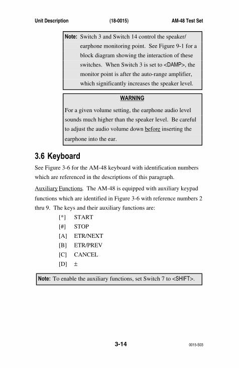
Note: Switch 3 and Switch 14 control the speaker/
earphone monitoring point. See Figure 9-1 for a
block diagram showing the interaction of these
switches. When Switch 3 is set to <DAMP>, the
monitor point is after the auto-range amplifier,
which significantly increases the speaker level.
WARNING
For a given volume setting, the earphone audio level
sounds much higher than the speaker level. Be careful
to adjust the audio volume down before inserting the
earphone into the ear.
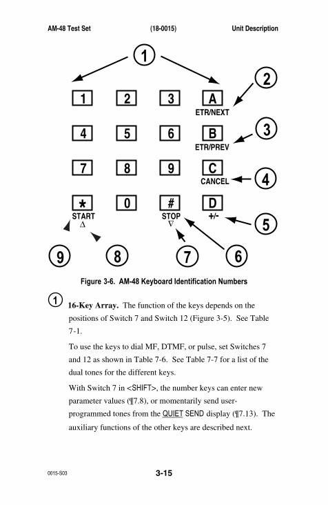
3.6 KeyboardSee Figure 3-6 for the AM-48 keyboard with identification numbers
which are referenced in the descriptions of this paragraph.
Auxiliary Functions . The AM-48 is equipped with auxiliary keypad
functions which are identified in Figure 3-6 with reference numbers 2
thru 9. The keys and their auxiliary functions are:
[*] START
[#] STOP
[A] ETR/NEXT
[B] ETR/PREV
[C] CANCEL
[D] ±
Note: To enable the auxiliary functions, set Switch 7 to <SHIFT>.
AM-48 Test Set (18-0015) Unit Description
0015-S03 3-15
ETR/NEXT
ETR/PREV
CANCEL
STOPSTART +/-∇
∇
21 A3
54 B6
87 C9
0* D#
12
3
4
5
6789Figure 3-6. AM-48 Keyboard Identification Numbers
1 16-Key Array. The function of the keys depends on the
positions of Switch 7 and Switch 12 (Figure 3-5). See Table
7-1.
To use the keys to dial MF, DTMF, or pulse, set Switches 7
and 12 as shown in Table 7-6. See Table 7-7 for a list of the
dual tones for the different keys.
With Switch 7 in <SHIFT>, the number keys can enter new
parameter values (¶7.8), or momentarily send user-
programmed tones from the QUIET SEND display (¶7.13). The
auxiliary functions of the other keys are described next.
Unit Description (18-0015) AM-48 Test Set
0015-S033-16
2 3 [ETR/NEXT], [ETR/PREV]. These keys have a dual
function:
A. To enter new parameter values into memory.
B. To scroll through multiple displays.
After using the number keys to input a new parameter value:
1) Press either [ETR/NEXT] or [ETR/PREV] to enter the
new value into memory.
2) Then press [ETR/NEXT] to step to the next display, or
press [ETR/PREV] to step to the previous display.
If no change was made to the display, or a change was made
with the [∆] or [∇] keys, press [ETR/NEXT or [ETR/PREV] once
to go immediately to the next/previous display. See ¶7.8 for
complete details.
4 [CANCEL]. Press [CANCEL] to erase a value input with the
number keys. The display defaults to the previous value. To
erase an input, press [CANCEL] before pressing [ETR/NEXT] or
[ETR/PREV]. [CANCEL] does not operate after pressing [∆] or
[∇] to change a value. See ¶7.8 for complete details.
5 [±]. This key is used to designate a positive or negative
polarity for a new parameter value input with the number keys.
See ¶7.8 for complete details.
AM-48 Test Set (18-0015) Unit Description
0015-S03 3-17
6 9 [START], [STOP]. These keys are used in the IMPLS
(impulse noise) and TRANS (transients, i.e., impulse noise,
phase hits, gain hits, and dropouts) modes to stop/start the
timed test. See ¶7.24 for information on timed tests. The
[START][STOP] functions are in operation only when data is
displayed, i.e., not when a user-entered parameter is displayed.
With a user-entered parameter displayed, these same keys take
on the functions explained for number 7 and 8.
7 8 [∆∆∆∆] / [∇]. Press [∆] or [∇] to step the value of any variable
number displayed either up or down. Hold down [∆] or [∇] for
one (1) second to enable auto-repeat mode and step in
increments ten (10) times the normal increments. See Table
7-2 for the values of the increments, depending on the
parameter.
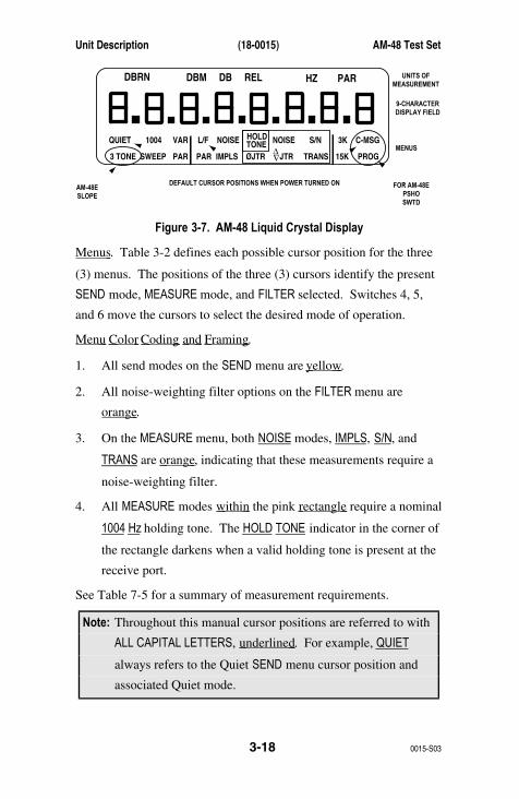
3.7 DisplayFigure 3-7 shows the AM-48 liquid crystal display:
1. The top line in Figure 3-7 shows all the possible units of
measurement. The units of measurement appear as appropriate
to label the value(s) displayed in the main display field. Time
and Count parameters do not show the units on the display.
2. The main display field has nine (9) 7-segmented characters with
decimal points. The prompts that appear on the display are
"pseudo-alpha" because of the limitations of the 7-segmented
characters. There are three (3) possible types of display fields,
as explained in ¶7.4.
3. Below the main display field are the menus for the three (3)
cursors, shown in detail in Table 3-2.
Unit Description (18-0015) AM-48 Test Set
0015-S033-18
3K C-MSG
15K PROG
QUIET
DBRN DBM DB REL HZ PAR
1004 VAR
PAR
L/F
PAR3 TONE SWEEP
NOISE NOISE S/NHOLDTONE
IMPLS ØJTR JTR TRANS∇∆
UNITS OFMEASUREMENT
9-CHARACTERDISPLAY FIELD
MENUS
FOR AM-48EPSHOSWTD
AM-48ESLOPE
DEFAULT CURSOR POSITIONS WHEN POWER TURNED ON
Figure 3-7. AM-48 Liquid Crystal Display
Menus . Table 3-2 defines each possible cursor position for the three
(3) menus. The positions of the three (3) cursors identify the present
SEND mode, MEASURE mode, and FILTER selected. Switches 4, 5,
and 6 move the cursors to select the desired mode of operation.
Menu Color Coding and Framing .
1. All send modes on the SEND menu are yellow .
2. All noise-weighting filter options on the FILTER menu are
orange .
3. On the MEASURE menu, both NOISE modes, IMPLS, S/N, and
TRANS are orange , indicating that these measurements require a
noise-weighting filter.
4. All MEASURE modes within the pink rectangle require a nominal
1004 Hz holding tone. The HOLD TONE indicator in the corner of
the rectangle darkens when a valid holding tone is present at the
receive port.
See Table 7-5 for a summary of measurement requirements.
Note: Throughout this manual cursor positions are referred to with
ALL CAPITAL LETTERS, underlined . For example, QUIET
always refers to the Quiet SEND menu cursor position and
associated Quiet mode.

AM-48 Test Set (18-0015) Unit Description
0015-S03 3-19
The SEND menu is yellow , the MEASURE menu is pink and orange ,
and the FILTER menu is orange .
Table 3-2. AM-48 SEND, MEASURE, and FILTER Menus
SEND MODES
AM-48 ONLY:
AM-48 ONLY:
QUIET
1004
VAR
Passive ResistorTermination
3TONE 404 Hz, 1004 Hz,2804 Hz for 5 sec.Cyclic @ SelectedLevel
AM-48E ONLY:
SLOPE 404 Hz, 1004 Hz,2004 Hz, 3004 Hzfor 5 sec. Cyclic@ Selected Level
SWEEP Tones Steppedper SelectedLevel, Start/StopFrequencies,Step Size andSweep Rate
TRANS Transients(Timed Tests):Impulse Noise,Phase Hits,Gain Hits,Dropouts
PAR Peak-to-AverageRatio Waveform@ Selected Level
1004 Hz Tone@ Selelcted Level
Variable ContinuousFrequency & Level
MEASURE MODES
MEASURE MODES LISTED BELOWNEED 1004 HZ HOLD TONE
L/F
NOISE
PAR
Level/Frequency
Idle ChannelNoise
IMPLS Impulse Noise(Timed Test)
Peak-to-AverageRatio withReceive Level
FILTER OPTIONS
3K 3 kHZ
15K 15 kHZ
C-MSG C-Message
PROG Program
AM-48E ONLY:
PSHO Psophometric
SWTD Sound-Weighted
NOISE
S/N
Notched Noise
∅ JTR Phase Jitter
JTR Amplitude Jitter
Signal-to-NoiseRatio
∇∆
3.8 Microphone/SpeakerThe speaker is for "listening" on the send or receive pairs, and the
microphone is for "talking" on the send pair. See ¶7.38.
Pressing Switch 14 to <TALK> (momentary position) activates the
microphone.
Unit Description (18-0015) AM-48 Test Set
0015-S033-20
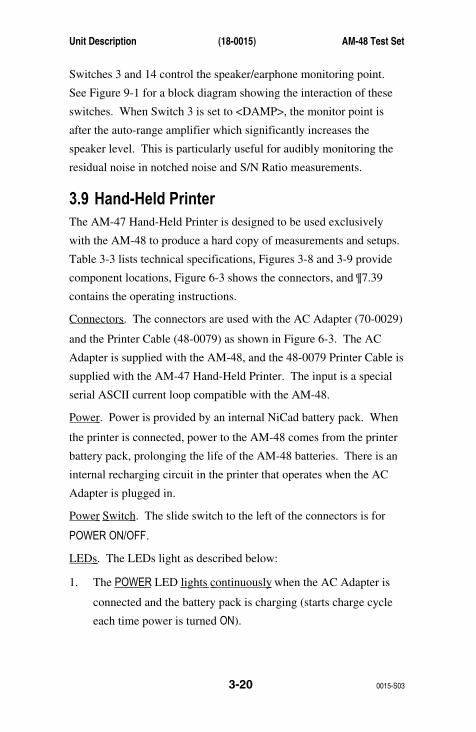
Switches 3 and 14 control the speaker/earphone monitoring point.
See Figure 9-1 for a block diagram showing the interaction of these
switches. When Switch 3 is set to <DAMP>, the monitor point is
after the auto-range amplifier which significantly increases the
speaker level. This is particularly useful for audibly monitoring the
residual noise in notched noise and S/N Ratio measurements.
3.9 Hand-Held PrinterThe AM-47 Hand-Held Printer is designed to be used exclusively
with the AM-48 to produce a hard copy of measurements and setups.
Table 3-3 lists technical specifications, Figures 3-8 and 3-9 provide
component locations, Figure 6-3 shows the connectors, and ¶7.39
contains the operating instructions.
Connectors . The connectors are used with the AC Adapter (70-0029)
and the Printer Cable (48-0079) as shown in Figure 6-3. The AC
Adapter is supplied with the AM-48, and the 48-0079 Printer Cable is
supplied with the AM-47 Hand-Held Printer. The input is a special
serial ASCII current loop compatible with the AM-48.
Power . Power is provided by an internal NiCad battery pack. When
the printer is connected, power to the AM-48 comes from the printer
battery pack, prolonging the life of the AM-48 batteries. There is an
internal recharging circuit in the printer that operates when the AC
Adapter is plugged in.
Power Switch . The slide switch to the left of the connectors is for
POWER ON/OFF.
LEDs . The LEDs light as described below:
1. The POWER LED lights continuously when the AC Adapter is
connected and the battery pack is charging (starts charge cycle
each time power is turned ON).
AM-48 Test Set (18-0015) Unit Description
0015-S03 3-21
2. The POWER LED blinks when power is ON and the battery pack
has been charged.
3. The SIGNAL LED lights when data is being received from the
AM-48.
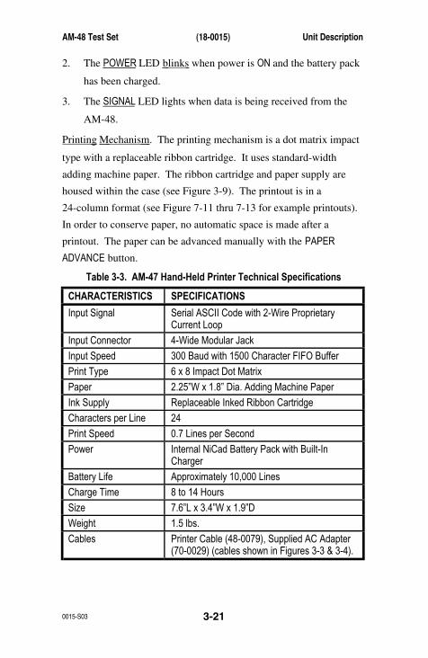
Printing Mechanism . The printing mechanism is a dot matrix impact
type with a replaceable ribbon cartridge. It uses standard-width
adding machine paper. The ribbon cartridge and paper supply are
housed within the case (see Figure 3-9). The printout is in a
24-column format (see Figure 7-11 thru 7-13 for example printouts).
In order to conserve paper, no automatic space is made after a
printout. The paper can be advanced manually with the PAPER
ADVANCE button.
Table 3-3. AM-47 Hand-Held Printer Technical Specifications
CHARACTERISTICS SPECIFICATIONS
Input Signal Serial ASCII Code with 2-Wire ProprietaryCurrent Loop
Input Connector 4-Wide Modular Jack
Input Speed 300 Baud with 1500 Character FIFO Buffer
Print Type 6 x 8 Impact Dot Matrix
Paper 2.25”W x 1.8” Dia. Adding Machine Paper
Ink Supply Replaceable Inked Ribbon Cartridge
Characters per Line 24
Print Speed 0.7 Lines per Second
Power Internal NiCad Battery Pack with Built-InCharger
Battery Life Approximately 10,000 Lines
Charge Time 8 to 14 Hours
Size 7.6”L x 3.4”W x 1.9”D
Weight 1.5 lbs.
Cables Printer Cable (48-0079), Supplied AC Adapter(70-0029) (cables shown in Figures 3-3 & 3-4).

Unit Description (18-0015) AM-48 Test Set
0015-S033-22
TOP VIEW
PUSH UP HERETO REMOVE COVER
PAPER CUTTER
BATTERY CHARGE/POWER LED DATA RECEIVE LED
PAPER FEEDBUTTON
PAPER ROLLCOMPARTMENT(See Figure 3-9)
POWER SWITCH AC ADAPTER PLUG
END VIEW
AmeritecHAND-HELD PRINTER • Model AM-47
PAPERADVANCE
POWER SIGNAL
POWEROFF ON
9VDCIN
SIGNALIN
Figure 3-8. Hand-Held Printer, External View

AM-48 Test Set (18-0015) Unit Description
0015-S03 3-23
MANUALRIBBONTAKE-UP
RIBBON CARTRIDGE
RIBBON
PUSH DOWNHERE TO
EJECT RIBBONCARTRIDGE
PAPER CUTTER
PUSH (PAPER ADVANCE)BUTTON TO ROUTEPAPER THROUGH
FEED PAPERINTO SLOT
INSTALLPAPERROLL
PAPER ROLL COMPARTMENT
PAPER ROLL INSTALLATION
PAPER ROLL
3 21
Figure 3-9. Hand-Held Printer, Internal View

Unit Description (18-0015) AM-48 Test Set
0015-S033-24
3.10 Impedance AdapterThe Impedance Adapter (24-0005) is illustrated in Figure 3-10. It is
used to match the AM-48 to:
1. Line impedance other than 600 Ohms or 900 Ohms
2. 4-Wire split impedances
The Impedance Adapter has settings for five (5) different impedances
to match the AM-48 to the user interface. It plugs into the RJ11
modular connector of the AM-48. See ¶6.5 for installation, and ¶7.41
for measurement corrections when the Impedance Adapter is used.
The schematic of the Impedance Adapter is shown in Figure 9-2.
THRU
1200 Ω
900 Ω
150 Ω
135 Ω
75 Ω
4W/2WSEND
UPPERKNOB
RJ11 PLUG
RJ11 JACK
Ameritec
IMPEDANCE ADAPTERMODEL 240005
CORPORATION COVINA, CA. U S A
SET AM4 SERIES TEST SET FOR 600 Ω
THRU
1200 Ω
900 Ω
150 Ω
135 Ω
75 Ω
4WRCV
LOWERKNOB
Figure 3-10. Impedance Adapter
AM-48 Test Set (18-0015) Power Considerations
0015-S04 4-1
4 POWER CONSIDERATIONS
4.1 GeneralThis section covers AM-48 power considerations, including battery
installation, AC Adapter connection, and the power on/off switch.
The AM-48 runs on internal battery or external AC power. Flashing
display decimal points indicate low batteries; alkaline batteries need
replacing, and NiCad batteries need recharging.
Low-Level Noise Measurements . Power the AM-48 with batteries
when making a low-level noise measurement. Do not power the
AM-48 with the AC Adapter for this test, because interference from
the AC source can affect the measurement.
4.2 Battery CompartmentThe battery compartment under the rear panel is accessed through a
removable slide door. The compartment takes four (4) AA 1.5-volt
alkaline or NiCad batteries. The battery compartment also serves as a
recharger for NiCad batteries when the AM-48 is connected to 115
VAC with the AC Adapter.
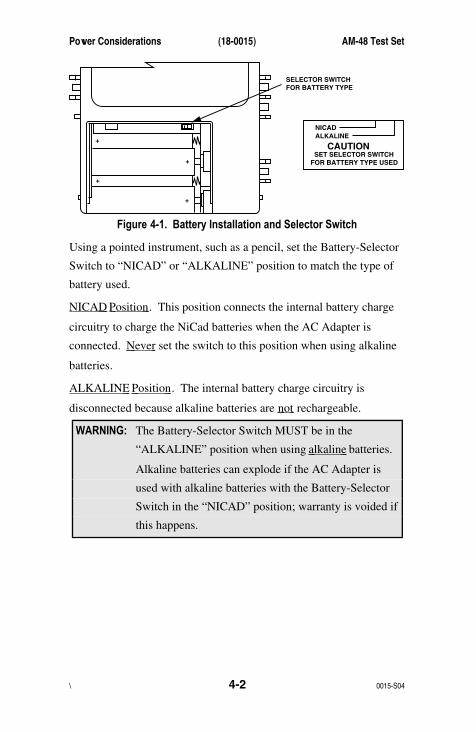
4.3 Battery-Selector SwitchThe Battery-Selector Switch is on the inside edge of the battery
compartment as shown in Figure 4-1.
Power Considerations (18-0015) AM-48 Test Set
\ 0015-S044-2
+
+
+
+
NICADALKALINE
CAUTION SET SELECTOR SWITCHFOR BATTERY TYPE USED
SELECTOR SWITCHFOR BATTERY TYPE
Figure 4-1. Battery Installation and Selector Switch
Using a pointed instrument, such as a pencil, set the Battery-Selector
Switch to “NICAD” or “ALKALINE” position to match the type of
battery used.
NICAD Position . This position connects the internal battery charge
circuitry to charge the NiCad batteries when the AC Adapter is
connected. Never set the switch to this position when using alkaline
batteries.
ALKALINE Position . The internal battery charge circuitry is
disconnected because alkaline batteries are not rechargeable.
WARNING: The Battery-Selector Switch MUST be in the
“ALKALINE” position when using alkaline batteries.
Alkaline batteries can explode if the AC Adapter is
used with alkaline batteries with the Battery-Selector
Switch in the “NICAD” position; warranty is voided if
this happens.
AM-48 Test Set (18-0015) Power Considerations
0015-S04 4-3
4.4 Battery InstallationTo install the batteries:
1. Slide off the battery compartment cover.
2. Set the Battery-Selector Switch per ¶4.3.
3. Lay the ribbon in the base of the compartment (to be able to pull
up on the ribbon for easy removal of the batteries).
4. Install four (4) 1.5-volt AA NiCad or Alkaline batteries as
shown in Figure 4-1.
5. Replace the battery compartment cover.
4.5 Battery InformationGeneral . When new, each battery will furnish approximately 1.5
Volts. The batteries are wired in series, supplying 6 VDC nominal.
An internal DC-to-DC Converter allows operation until the batteries
have discharged to approximately 3 Volts.
To avoid battery chemical leakage :
1. Use only first quality batteries
2. Do not subject the AM-48 to excessively high temperatures.
The warranty does not cover damage resulting from battery leakage.
Alkaline Batteries . The AM-48 is shipped with four (4) high-quality
alkaline batteries, which give approximately 6-7 hours of service.
When the batteries have discharged to approximately 3.5 volts, the
display decimal points will flash. The flashing indicates
approximately 30 minutes of remaining operating life.
Power Considerations (18-0015) AM-48 Test Set
\ 0015-S044-4
NiCad Batteries . Commercially available AA size Nickel Cadmium
(rechargeable) batteries can be used, but operating life will be
reduced to approximately 3 to 4 hours because of the limited energy
storage capacity of rechargeable batteries. Due to the abrupt end-of-
life discharge curve of Nickel Cadmium batteries, the flashing
decimal points low-battery indication will only provide a few minutes
of warning before the end of operation.
4.6 AC PowerTo power the AM-48 with 115 VAC, plug one end of the AC Adapter
(70-0029) into the <DC 9V> connector on the bottom of the unit, and
the other end into an AC wall jack. See Figure 3-3 for the AC
Adapter, and Figure 3-2 for the AC Adapter plug on the AM-48.
The AC Adapter supplies 9 VDC to the AM-48. The locations of the
+ and – DC voltage contacts on the 2.5 mm jack of the AC Adapter
are illustrated on the transformer housing of the AC Adapter itself.
When using the AM-47 Hand-Held Printer, the AC Adapter can be
used to maintain the charge of the printer batteries that power the
AM-48. See Figure 6-3 for connections.
4.7 Power On/Off SwitchThe Power On/Off Switch is a combination toggle switch and
momentary switch located at the top right-hand side of the AM-48
(Switch 1 in Figure 3-5).
Automatic Power Shutdown . To allow the AM-48 to power down by
itself, momentarily press the switch toward the <ON/OFF> position to
turn the power on. If the unit is left unattended, the power will shut
off automatically after the TIME OFF setting (see ¶7.12.4 for
instructions to set the time).

AM-48 Test Set (18-0015) Power Considerations
0015-S04 4-5
Continuous Power On . Set the switch to the <ON> position for power
to be on continuously.
Note: To turn power on continuously when battery voltage is less
than about 5 VDC, first turn power ON in momentary
<ON/OFF> position, then set switch to <ON>.
Power Off . To turn the power off, momentarily press the switch
toward the <ON/OFF> position.
The position of Switch 2 determines the initial display. The default
power-up cursor positions are shown in Figure 3-7.
AM-48 Test Set (18-0015) Self-Test Instructions
0015-S05 5-1
5 SELF-TEST INSTRUCTIONS
5.1 GeneralPurpose . This section has two (2) objectives:
1. To practice the main AM-48 operating procedures.
2. To verify that the AM-48 is working properly.
General . Each test in this section is described and illustrated. In the
figures, circled letters correspond to the steps of the written
description; circled numbers identify the switches.
Note: Power is ON for the tests in this section. See Section 4
concerning connecting and turning on power to the AM-48.
5.2 Self-Test SetupSelf-Test Setup is depicted in Figures 5-1 and 5-2.
Cable Connection . The tests in this section are done with the AM-48
looped back on itself, not connected to any external equipment. Plug
in the Modular-to-Minigator Cable (48-0049) (supplied with the
AM-48), and connect the minigator clips as shown in Figure 5-1.
The signals sent (generated) through the send port are routed directly
back to the receive port.

Self-Test Instructions (18-0015) AM-48 Test Set
0015-S055-2
Ameritec
PERSONAL TRANSMISSION TEST SET
MODEL AM-48
SEND
MEASURE
FILTER
ON
ABSRELSEND
ON/OFF
∇
∇
∇
DAMP ∇ ∇
OFFSEL
900Ω600Ω
∇∇
∇SEL
∇
∇
SEL
∇
∇
3KC-MSG
15KPROG
QUIET1004
VARPAR L/F
PAR
3 TONESWEEP
NOISE
NOISES/N
HOLDTONE
IMPLSØJTR
JTRTRANS
∇∆ •
•
MON RCV
MON SNDTALK
∇TERM
∇
BRDG
∇
∇•
4W•
TONEPULSEON HK
∇∇•
MFDTMFSHIFT
ETR/NEXTETR/PREV
CANCEL
STOP
START
4W/2WSND 4WRCV +/-
∇
∇
∇
∇
∇
2W4W REV
MIC
VOL
PRTEAR DC9V
∇
∇
∇
•SF SKPNORX TONE
∇
RCL/STO ∇ ∇
•PRINT ∇
2
1
A
35
4
B
68
7
C
90
*
D
#
Red (R)
Black (R1)
Green (T)
Yellow (T1)
Figure 5-1. AM-48 Setup for Self-Test (Looped Back)

AM-48 Test Set (18-0015) Self-Test Instructions
0015-S05 5-3
General Switch Setup . Figure 5-2 shows the initial positions of the
switches for the tests in this section. Leave these switches in the
positions indicated unless otherwise directed in the instructions for
the individual tests. Switches are referenced by the circled numbers.
AmeritecPERSONAL TRANSMISSION TEST SET
MODEL AM-48
SEND MEASURE FILTER
(ABS)
(DAMP)
(SHIFT)
(NOR)
(4W)
(600 Ω)
(ON HK)
(TERM)
(MON SND)
ON
ABSREL
SEND
ON/OFF
∇
∇
∇
DAMP
∇
∇
OFF
SEL
900Ω600Ω
∇
∇
∇
SEL
∇
∇
SEL
∇
∇
3K C-MSG
15K PROG
QUIET 1004 VAR
PAR
L/F
PAR3 TONE SWEEP
NOISE NOISE S/NHOLDTONE
IMPLS ØJTR JTR TRANS∇∆
•
•
MON RCVMON SNDTALK
∇
TERM∇
BRDG∇
∇•
4W•
TONEPULSEON HK
∇
∇•
MFDTMFSHIFT
ETR/NEXT
ETR/PREV
CANCEL
STOPSTART
4W/2WSND
4WRCV
+/-
∇
∇
∇
∇
∇
2W
4W REV
MIC
VOL
PRT EARDC9V
∇
∇
∇
•
SF SKPNOR
X TONE
∇
RCL/STO
∇
∇
•
∇
21 A3
54 B6
87 C9
0* D#
15
14
13
12
11
1
2
3
8
9
4
5
6
7
10
Figure 5-2. General Switch Setup for Self Test
Switches 4, 5, 6, and 9 do not have a set position because they are all
dual momentary switches. The instructions for each test will indicate
when to rock switches 5 and 6 to move the cursors to desired
positions on the display menus.
Self-Test Instructions (18-0015) AM-48 Test Set
0015-S055-4
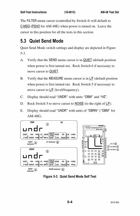
The FILTER menu cursor (controlled by Switch 4) will default to
C-MSG (PSHO for AM-48E) when power is turned on. Leave the
cursor in this position for all the tests in this section.
5.3 Quiet Send ModeQuiet Send Mode switch settings and display are depicted in Figure
5-3.
A. Verify that the SEND menu cursor is in QUIET (default position
when power is first turned on). Rock Switch 6 if necessary to
move cursor to QUIET.
B. Verify that the MEASURE menu cursor is in L/F (default position
when power is first turned on). Rock Switch 5 if necessary to
move cursor to L/F (level/frequency).
C. Display should read “UNDR” with units “DBM” and “HZ”.
D. Rock Switch 5 to move cursor to NOISE (to the right of L/F).
E. Display should read “UNDR” with units of “DBRN” (“DBM” for
AM-48E).
AmeritecPERSONAL TRANSMISSION TEST SET
MODEL AM-48
SEND MEASURE FILTER
ON
ABSREL
SEND
ON/OFF
∇
∇
∇
DAMP
∇
∇
OFF
SEL
900Ω600Ω
∇
∇
∇
SEL
∇
∇
SEL
∇
∇
3K C-MSG
15K PROG
QUIET 1004 VAR
PAR
L/F
PAR3 TONE SWEEP
NOISE NOISE S/NHOLDTONE
IMPLS ØJTR JTR TRANS∇∆
•
•
MON RCVMON SNDTALK
∇
TERM∇
BRDG
∇∇•
4W•
TONEPULSEON HK
∇
∇•
MFDTMFSHIFT
ETR/NEXT
ETR/PREV
CANCEL
STOPSTART
4W/2WSND
4WRCV
+/-
∇
∇
∇
∇
∇
2W
4W REV
MIC
VOL
PRT EARDC9V
∇
∇
∇
•
SF SKPNOR
X TONE
∇
RCL/STO
∇
∇
•
∇
21 A3
54 B6
87 C9
0* D#
5
B
D
A6
Set L/F
Set NOISE
Set QUIET
A B
C
3K C-MSG
15K PROG
QUIET
DBM HZ
1004 VAR
PAR
L/F
PAR3 TONE SWEEP
NOISE NOISE S/NHOLDTONE
IMPLS ØJTR JTR TRANS∇∆
QUIETdarkened
L/F darkened
A D
E
3K C-MSG
15K PROG
QUIET
DBRN
1004 VAR
PAR
L/F
PAR3 TONE SWEEP
NOISE NOISE S/NHOLDTONE
IMPLS ØJTR JTR TRANS∇∆
QUIETdarkened
NOISE darkened
Figure 5-3. Quiet Send Mode Self Test
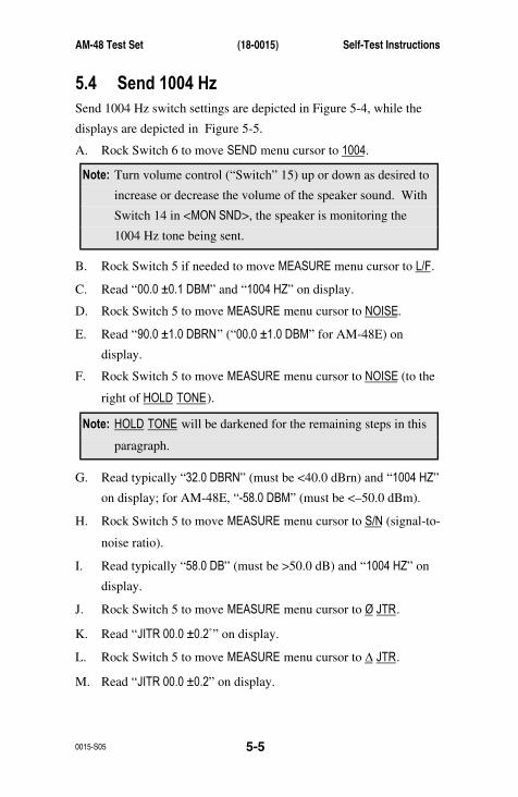
AM-48 Test Set (18-0015) Self-Test Instructions
0015-S05 5-5
5.4 Send 1004 HzSend 1004 Hz switch settings are depicted in Figure 5-4, while the
displays are depicted in Figure 5-5.
A. Rock Switch 6 to move SEND menu cursor to 1004.
Note: Turn volume control (“Switch” 15) up or down as desired to
increase or decrease the volume of the speaker sound. With
Switch 14 in <MON SND>, the speaker is monitoring the
1004 Hz tone being sent.
B. Rock Switch 5 if needed to move MEASURE menu cursor to L/F.
C. Read “00.0 ±0.1 DBM” and “1004 HZ” on display.
D. Rock Switch 5 to move MEASURE menu cursor to NOISE.
E. Read “90.0 ±1.0 DBRN” (“00.0 ±1.0 DBM” for AM-48E) on
display.
F. Rock Switch 5 to move MEASURE menu cursor to NOISE (to the
right of HOLD TONE).
Note: HOLD TONE will be darkened for the remaining steps in this
paragraph.
G. Read typically “32.0 DBRN” (must be <40.0 dBrn) and “1004 HZ”
on display; for AM-48E, “-58.0 DBM” (must be <–50.0 dBm).
H. Rock Switch 5 to move MEASURE menu cursor to S/N (signal-to-
noise ratio).
I. Read typically “58.0 DB” (must be >50.0 dB) and “1004 HZ” on
display.
J. Rock Switch 5 to move MEASURE menu cursor to Ø JTR.
K. Read “JITR 00.0 ±0.2˚” on display.
L. Rock Switch 5 to move MEASURE menu cursor to ∆ JTR.
M. Read “JITR 00.0 ±0.2” on display.
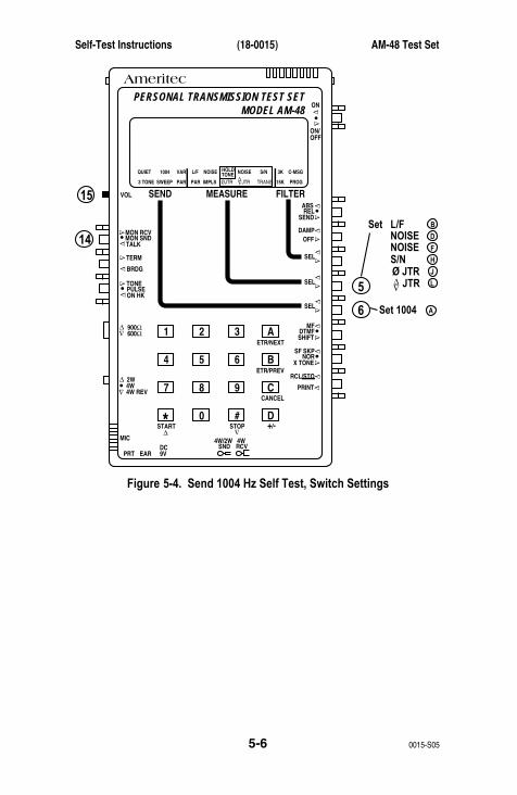
Self-Test Instructions (18-0015) AM-48 Test Set
0015-S055-6
AmeritecPERSONAL TRANSMISSION TEST SET
MODEL AM-48
SEND MEASURE FILTER
ON
ABSREL
SEND
ON/OFF
∇
∇
∇
DAMP
∇
∇
OFF
SEL
900Ω600Ω
∇
∇
∇
SEL
∇
∇SEL
∇
∇
3K C-MSG
15K PROG
QUIET 1004 VAR
PAR
L/F
PAR3 TONE SWEEP
NOISE NOISE S/NHOLDTONE
IMPLS ØJTR JTR TRANS∇∆
∇∆
•
•
MON RCVMON SNDTALK
∇
TERM∇
BRDG
∇∇•
4W•
TONEPULSEON HK
∇
∇•
MFDTMFSHIFT
ETR/NEXT
ETR/PREV
CANCEL
STOPSTART
4W/2WSND
4WRCV
+/-
∇
∇
∇
∇
∇
2W
4W REV
MIC
VOL
PRT EARDC9V
∇
∇
∇
•
SF SKPNOR
X TONE
∇
RCL/STO
∇
∇
•
∇
21 A3
54 B6
87 C9
0* D#
5
15
14B
D
F
H
J
L
A6
Set L/FNOISENOISES/NØ JTR JTR
Set 1004
Figure 5-4. Send 1004 Hz Self Test, Switch Settings
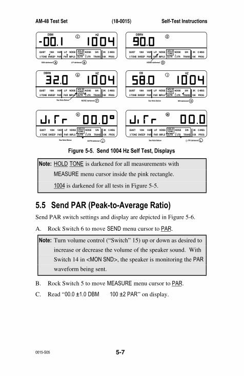
AM-48 Test Set (18-0015) Self-Test Instructions
0015-S05 5-7
3K C-MSG
15K PROG
QUIET
DBRN HZ
1004 VAR
PAR
L/F
PAR3 TONE SWEEP
NOISE NOISE S/NHOLDTONE
IMPLS ØJTR JTR TRANS∇∆
G
3K C-MSG
15K PROG
QUIET
DB HZ
1004 VAR
PAR
L/F
PAR3 TONE SWEEP
NOISE NOISE S/NHOLDTONE
IMPLS ØJTR JTR TRANS∇∆
See Note BelowSee Note Below S/N darkened
••
See Note BelowSee Note Below
I
H
3K C-MSG
15K PROG
QUIET 1004 VAR
PAR
L/F
PAR3 TONE SWEEP
NOISE NOISE S/NHOLDTONE
IMPLS ØJTR JTR TRANS∇∆
K
3K C-MSG
15K PROG
QUIET 1004 VAR
PAR
L/F
PAR3 TONE SWEEP
NOISE NOISE S/NHOLDTONE
IMPLS ØJTR JTR TRANS∇∆
∇∆ JTR darkened
••
M
L
3K C-MSG
15K PROG
QUIET
DBM HZ
1004 VAR
PAR
L/F
PAR3 TONE SWEEP
NOISE NOISE S/NHOLDTONE
IMPLS ØJTR JTR TRANS∇∆
1004 darkened L/F darkened
•
C
A B
3K C-MSG
15K PROG
QUIET
DBRN
1004 VAR
PAR
L/F
PAR3 TONE SWEEP
NOISE NOISE S/NHOLDTONE
IMPLS ØJTR JTR TRANS∇∆
NOISE darkened
•
E
D
NOISE darkened F
ØJTR darkened J
Figure 5-5. Send 1004 Hz Self Test, Displays
Note: HOLD TONE is darkened for all measurements with
MEASURE menu cursor inside the pink rectangle.
1004 is darkened for all tests in Figure 5-5.
5.5 Send PAR (Peak-to-Average Ratio)Send PAR switch settings and display are depicted in Figure 5-6.
A. Rock Switch 6 to move SEND menu cursor to PAR.
Note: Turn volume control (“Switch” 15) up or down as desired to
increase or decrease the volume of the speaker sound. With
Switch 14 in <MON SND>, the speaker is monitoring the PAR
waveform being sent.
B. Rock Switch 5 to move MEASURE menu cursor to PAR.
C. Read “00.0 ±1.0 DBM 100 ±2 PAR” on display.
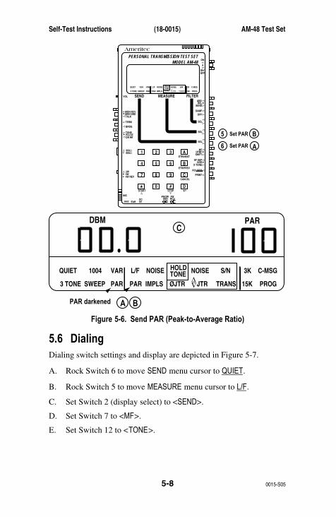
Self-Test Instructions (18-0015) AM-48 Test Set
0015-S055-8
AmeritecPERSONAL TRANSMISSION TEST SET
MODEL AM-48
SEND MEASURE FILTER
ON
ABSREL
SEND
ON/OFF
∇
∇
∇
DAMP
∇
∇
OFF
SEL
900Ω600Ω
∇
∇
∇
SEL∇
∇
SEL
∇
∇
3K C-MSG
15K PROG
QUIET 1004 VAR
PAR
L/F
PAR3 TONE SWEEP
NOISE NOISE S/NHOLDTONE
IMPLS ØJTR JTR TRANS∇∆
•
•
MON RCVMON SNDTALK
∇TERM∇
BRDG
∇∇•
4W•
TONEPULSEON HK
∇
∇•
MFDTMFSHIFT
ETR/NEXT
ETR/PREV
CANCEL
STOPSTART
4W/2WSND
4WRCV
+/-
∇
∇
∇
∇
∇
2W
4W REV
MIC
VOL
PRT EARDC9V
∇
∇
∇
•
SF SKPNOR
X TONE
∇
RCL/STO
∇
∇
•
∇
21 A3
54 B6
87 C9
0* D#
5 B
A6
Set PAR
Set PAR
A B
C
3K C-MSG
15K PROG
QUIET
DBM PAR
1004 VAR
PAR
L/F
PAR3 TONE SWEEP
NOISE NOISE S/NHOLDTONE
IMPLS ØJTR JTR TRANS∇∆
PAR darkened
•
Figure 5-6. Send PAR (Peak-to-Average Ratio)
5.6 DialingDialing switch settings and display are depicted in Figure 5-7.
A. Rock Switch 6 to move SEND menu cursor to QUIET.
B. Rock Switch 5 to move MEASURE menu cursor to L/F.
C. Set Switch 2 (display select) to <SEND>.
D. Set Switch 7 to <MF>.
E. Set Switch 12 to <TONE>.
AM-48 Test Set (18-0015) Self-Test Instructions
0015-S05 5-9
F. Turn volume control (“Switch” 15) all the way up for maximum
speaker volume.
G. Press various keys on the keypad to dial MF (multiple
frequency) tones. Listen to the dual tones coming from the
speaker. The speaker will emit the tones as long as the key is
held down. Note that key [D] has no MF tones.
Note: See Table 7-7 for list of dual frequencies transmitted in tone
dialing.
H. When doing step G., the display will read “DIAL -10.0 DBM”.
This indicates that –10.0 dBm (factory setting) is the send level.
Tone dialing send level can be changed. See ¶7.12.3 and Figure
7-1 for “TTLEV” (Touch Tone Level) display.
I. Set Switch 7 to <DTMF>.
J. Press various keys on the keypad to dial DTMF (Dual Tone
Multiple Frequency) tones. Listen to the dual tones coming
from the speaker. The speaker will emit the tones as long as the
key is held down.
K. The display will read as in step H.
L. Set Switch 12 to <PULSE>.
M. Press the keys on the keypad and note that no sound is heard.
No battery is connected to the line and line battery voltage is
required for pulse dialing.
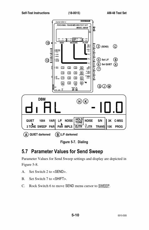
Self-Test Instructions (18-0015) AM-48 Test Set
0015-S055-10
AmeritecPERSONAL TRANSMISSION TEST SET
MODEL AM-48
SEND MEASURE FILTER
ON
ABSREL
SEND
ON/OFF
∇
∇
∇
DAMP
∇
∇
OFF
SEL
900Ω600Ω
∇
∇
∇
SEL∇
∇
SEL
∇
∇
3K C-MSG
15K PROG
QUIET 1004 VAR
PAR
L/F
PAR3 TONE SWEEP
NOISE NOISE S/NHOLDTONE
IMPLS ØJTR JTR TRANS∇∆
•
•
MON RCVMON SNDTALK
∇TERM∇
BRDG
∇∇•
4W•
TONEPULSEON HK
∇
∇•
MFDTMFSHIFT
ETR/NEXT
ETR/PREV
CANCEL
STOPSTART
4W/2WSND
4WRCV
+/-
∇
∇
∇
∇
∇
2W
4W REV
MIC
VOL
PRT EARDC9V
∇
∇
∇
•
SF SKPNOR
X TONE
∇
RCL/STO
∇
∇
•
∇
21 A3
54 B6
87 C9
0* D#
5
2
B
A6
7
15
12 Set L/F
C
G J M
(SEND)
Set QUIET
A B
H K
3K C-MSG
15K PROG
QUIET
DBM
1004 VAR
PAR
L/F
PAR3 TONE SWEEP
NOISE NOISE S/NHOLDTONE
IMPLS ØJTR JTR TRANS∇∆
QUIET darkened
•
L/F darkened
Figure 5-7. Dialing
5.7 Parameter Values for Send SweepParameter Values for Send Sweep settings and display are depicted in
Figure 5-8.
A. Set Switch 2 to <SEND>.
B. Set Switch 7 to <SHIFT>.
C. Rock Switch 6 to move SEND menu cursor to SWEEP.

AM-48 Test Set (18-0015) Self-Test Instructions
0015-S05 5-11
Note: The MEASURE menu cursor can be in any mode.
Turn volume control (“Switch” 15) up or down as desired to
increase or decrease the volume of the speaker sound. With
Switch 14 in <MON SND>, the speaker is monitoring the
frequencies being swept.
D. Display will read “00.0 DBM” and frequencies which start at “204
HZ” and increase in 100 Hz steps every second up to 19,904 Hz,
at which time the sweep starts again at 204 Hz.
E. Rock Switch 6 once to momentarily exit SWEEP mode. Rock
Switch 6 once in the opposite direction to re-enter SWEEP mode
(SEND menu cursor back to SWEEP). Note that the sweep starts
again at 204 Hz.
F. Press [ETR/NEXT] on the keypad ([A] key).
G. Display will change to “LEVL 00.0 DBM”. This is the first of
the five (5) default parameter settings shown in Figure 5-8.
H. Repeat Step F. four (4) more times and observe the NEXT
displays in sequence:
I. “STRT 204 HZ”
J. “STOP 19904 HZ”
K. “STEP 100 HZ”
L. “RATE 1.0”
M. Press [ETR/PREV] on the keypad ([B] key) five (5) times and
observe the PREVIOUS displays appear in reverse sequence.
Note: In the remaining steps, an example will be given of setting
new parameter values for the SWEEP mode. Carefully note
the procedure, because the same procedure is used for setting
all AM-48 parameter values.
Self-Test Instructions (18-0015) AM-48 Test Set
0015-S055-12
N. Repeat Step E. to start with the first SWEEP display.
O. Press [ETR/NEXT] to go to the NEXT display (sweep frequency
LEVEL).
P. Press [±], same as [D] key. Then press [5] and [0]. Display now
reads “LEVL -5.0 DBM”. Press [±] several times and notice the
“-“ sign appear and disappear. Leave display with the “-“.
Q. Press [ETR/NEXT] again. This enters the new LEVEL, -5.0 dBm.
R. Press [ETR/NEXT] to go to the NEXT display (START frequency
setting).
S. Press [4], [0], [0]. Display now reads “STRT 400 HZ”.
T. Press [ETR/NEXT] again. This enters the new START frequency,
400 Hz.
U. Press [ETR/NEXT] to go to the NEXT display (STOP frequency
setting).
V. Press [1], [6], [0], [0]. Display now reads “STOP 1600 HZ”.
W. Press [ETR/NEXT] again. This enters the new STOP frequency,
1600 Hz.
X. Press [ETR/NEXT] to go to the NEXT display (frequency STEP
setting).
Y. Display now reads “STEP 100 HZ”.
Note: In the next step, a “mistake” will be made when entering a
new parameter value to show how it can be corrected.
Z. Press [2], [0], [0]. Display now reads “STEP 200 HZ”. This is
a mistake; desired step is actually 300 Hz.
AA. Press [CANCEL], same as [C] key. The incorrect value is gone
and the display now reads as in Step Y.
BB. Press [3], [0], [0]. Display now reads “STEP 300 HZ”, the
desired value.

AM-48 Test Set (18-0015) Self-Test Instructions
0015-S05 5-13
CC. Press [ETR/NEXT] again. This enters the new frequency STEP,
300 Hz.
DD. Press [ETR/NEXT] to go to the NEXT display (RATE, i.e. duration
of each frequency in the sweep).
EE. Display now reads “RATE 1.0”.
FF. Press [∆] momentarily repeatedly and notice the time increase
0.1 sec at a time: 1.1, 1.2, 1.3. ….sec. Hold [∆] down
continuously and notice that the time starts increasing in steps of
1.0 sec; 2.0, 3.0, 4.0, ….sec. Press momentarily and/or hold
down [∇] and note that the time decreases in steps of 0.1 and/or
1.0 sec. Use [∆] and [∇] as necessary to step the time (rate) to
2.0 sec.
GG. Display now reads “RATE 2.0”.
HH. Press [ETR/NEXT] to return to the original display. Instead of the
sweep that was seen in Step D., there is now a new sweep that
reflects the settings just entered. Display now reads “-05.0 DBM”
and shows frequencies which start at “400 HZ” and increase in
300 Hz steps every 2 seconds up to 1600 Hz, at which time the
sweep starts again at 400 Hz.
Note: The new parameter settings will remain until (1) they are
changed, or (2) power is turned off. If power is turned off,
the settings will revert back to the default settings as shown
in Figure 5-8.
This completes the self test. See Section 7 for complete operating
instructions and details of other tests and parameter settings not
covered here.
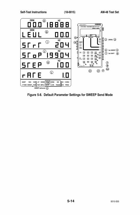
Self-Test Instructions (18-0015) AM-48 Test Set
0015-S055-14
AmeritecPERSONAL TRANSMISSION TEST SET
MODEL AM-48
SEND MEASURE FILTER
ON
ABSREL
SEND
ON/OFF
∇
∇
∇
DAMP
∇
∇
OFF
SEL
900Ω600Ω
∇
∇
∇
SEL
∇
∇
SEL
∇
∇
3K C-MSG
15K PROG
QUIET 1004 VAR
PAR
L/F
PAR3 TONE SWEEP
NOISE NOISE S/NHOLDTONE
IMPLS ØJTR JTR TRANS∇∆
•
•
MON RCVMON SNDTALK
∇
TERM∇
BRDG
∇∇•
4W•
TONEPULSEON HK
∇
∇•
MFDTMFSHIFT
ETR/NEXT
ETR/PREV
CANCEL
STOPSTART
4W/2WSND
4WRCV
+/-
∇
∇
∇
∇
∇
2W
4W REV
MIC
VOL
PRT EARDC9V
∇
∇
∇
•
SF SKPNOR
X TONE
∇
RCL/STO
∇
∇
•
∇
21 A3
54 B6
87 C9
0* D#
6 C
B
P
M
F
AA
7
15
14
Set SWEEP
2 A(SEND)
Set SHIFT
D
G
I
J
K
L
DBM
DBM
HZ
HZ
C
3K C-MSG
15K PROG
QUIET 1004 VAR
PAR
L/F
PAR3 TONE SWEEP
NOISE NOISE S/NHOLDTONE
IMPLS ØJTR JTR TRANS∇∆
SWEEP darkened
•
•
HZ
HZ
•
FFFF
Figure 5-8. Default Parameter Settings for SWEEP Send Mode
AM-48 Test Set (18-0015) Connection & Configuration
0015-S06 6-1
6. CONNECTION AND CONFIGURATION
6.1 IntroductionThis section describes the AM-48 connections and configurations
made in preparation for testing. It is divided into the following
paragraphs:
6.2 General
6.3 Connectors and Cables
6.4 600 Ohm/900 Ohm Line Termination Impedances
6.5 Impedance Adapter
6.6 Configurations
In ¶6.6, basic operating instructions are given for testing with the
Western Electric 829 loopback device, as well as with Ameritec
responders.
Note: Section 7 gives detailed AM-48 operating instructions and
Section 8 explains the meaning of the measurements.
6.2 GeneralLow-Level Noise Measurements . Power the AM-48 with batteries
when making a low-level noise measurement. Do not power the
AM-48 with the AC Adapter for this test because interference from
the AC source can affect the measurement.
“Dry” Circuit Measurements . Set Switch 12 (Figure 3-5) to <ON HK>
when making measurements on “dry” (4-wire only) circuits. “Dry”
circuits have no loop current.
Connection & Configuration (18-0015) AM-48 Test Set
0015-S066-2
Independent Send and Measure Modes . The Send, Measure, and
Filter modes of the AM-48 operate completely independently. Any
combination of Send, Measure, or Filter can be selected. However,
depending on the setup, the resulting measurements may or may not
be valid.
For example, a 1004 Hz holding tone must be sent for various measure
modes and a PAR waveform must be sent when PAR is measured. If
the 1004 Hz tone or PAR waveform were not present in the
corresponding measurement, the measurement would no be valid.
The AM-48 configuration (see ¶6.6) determines in what part of the
system the signals need to be sent and measured.
The correct Send, Measure, and Filter modes are indicated for each
test described in the operating instructions of Sections 5 and 7.
6.3 Connectors and CablesSee Figures 3-2 thru 3-4 for illustrations of the AM-48 connectors
and cables. Note that some cables are standard and others are
optional. Connect the appropriate cable(s) described in this
paragraph according to the desired application.
AC Adapter . Connect the circular connector of the AC Adapter to
the <DC 9V> AC Adapter Plug. Plug the two (2) prongs on the other
end into a standard 115 VAC wall socket. Observe the WARNING
in ¶4.3.
Earphone . The earphone can be used in place of the speaker. Use the
earphone to hear better in noisy environments or to listen without
disturbing other people in the area. See the WARNING in ¶3.5.15
before connecting the earphone. Plug the earphone into the <EAR>
Earphone Jack. Note that the internal speaker is disconnected when
the Earphone is plugged in.
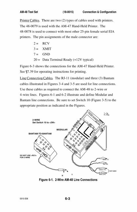
AM-48 Test Set (18-0015) Connection & Configuration
0015-S06 6-3
Printer Cables . There are two (2) types of cables used with printers.
The 48-0079 is used with the AM-47 Hand-Held Printer. The
48-0078 is used to connect with most other 25-pin female serial EIA
printers. The pin assignments of the male connector are:
2 = RCV
3 = XMIT
7 = GND
20 = Data Terminal Ready (+12V typical)
Figure 6-3 shows the connections for the AM-47 Hand-Held Printer.
See ¶7.39 for operating instructions for printing.
Line Connection Cables . The RJ-11 (modular) and three (3) Bantam
cables illustrated in Figures 3-4 and 3-5 are used for line connections.
Use these cables as required to connect the AM-48 to 2-wire or
4-wire lines. Figures 6-1 and 6-2 illustrate and define Modular and
Bantam line connections. Be sure to set Switch 10 (Figure 3-5) to the
appropriate position as indicated in the Figures.
Ameritec
PERSONAL TRANSMISSION TEST SET
MODEL AM-48
SEND
MEASURE
FILTER
ON
ABSRELSEND
ON/OFF
∇
∇
∇
DAMP ∇ ∇
OFFSEL
900Ω600Ω
∇∇
∇
SEL
∇
∇
SEL
∇
∇
3KC-MSG
15KPROG
QUIET1004
VARPAR L/F
PAR
3 TONESWEEP
NOISE
NOISES/N
HOLDTONE
IMPLSØJTR
JTRTRANS
∇∆ •
•
MON RCV
MON SNDTALK
∇
TERM
∇
BRDG
∇
∇•
4W•
TONEPULSEON HK
∇∇•
MFDTMFSHIFT
ETR/NEXTETR/PREV
CANCEL
STOP
START
4W/2WSND 4WRCV +/-
∇
∇
∇
∇
∇
2W4W REV
MIC
VOL
PRTEAR DC9V
∇
∇
∇
•SF SKPNORX TONE
∇
RCL/STO ∇ ∇
•PRINT ∇
2
1
A
35
4
B
68
7
C
90
*
D
#
Black (R1)
Green (T)
Red (R)
Yellow (T1)
Black (R1)
4W•
CANCEL
STOP
START
4W/2WSND 4WRCV +/-
∇
∇
2W4W REV
MIC
PRTEAR DC9V
∇
∇
8
7
C
90
*
D
#
2-WIRESet Switch 10 to <2W>
DO NOT USE <RCV>FOR 2-WIRE
MODULAR
BANTAM-TO-BANTAM
TR
NOT USED
T = TipR = Ring
Figure 6-1. 2-Wire AM-48 Line Connections
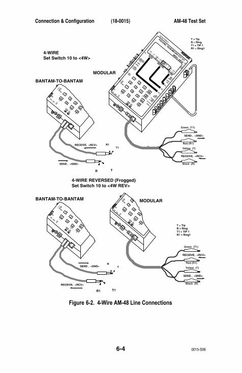
Connection & Configuration (18-0015) AM-48 Test Set
0015-S066-4
Ameritec
PERSONAL TRANSMISSION TEST SET
MODEL AM-48
SEND
MEASURE
FILTER
ON
ABSRELSEND
ON/OFF
∇
∇
∇
DAMP ∇ ∇
OFFSEL
900Ω600Ω
∇∇
∇
SEL
∇
∇
SEL
∇
∇
3KC-MSG
15KPROG
QUIET1004
VARPAR L/F
PAR
3 TONESWEEP
NOISE
NOISES/N
HOLDTONE
IMPLSØJTR
JTRTRANS
∇∆ •
•
MON RCV
MON SNDTALK
∇
TERM
∇
BRDG
∇
∇•
4W•
TONEPULSEON HK
∇∇•
MFDTMFSHIFT
ETR/NEXTETR/PREV
CANCEL
STOP
START
4W/2WSND 4WRCV +/-
∇
∇
∇
∇
∇
2W4W REV
MIC
VOL
PRTEAR DC9V
∇
∇
∇
•SF SKPNORX TONE
∇
RCL/STO ∇ ∇
•PRINT ∇
2
1
A
35
4
B
68
7
C
90
*
D
#
Red (R1)
Black (R)
Green (T1)
Yellow (T)
4W•
CANCEL
STOP
START
4W/2WSND 4WRCV +/-
∇
∇
2W4W REV
MIC
PRTEAR DC9V
∇
∇
8
7
C
90
*
D
#
4-WIRESet Switch 10 to <4W>
MODULAR
BANTAM-TO-BANTAM
TR
T1R1RECEIVE, <RCV>
RECEIVE, <RCV>
SEND , <SND>
SEND , <SND>
T = TipR = RingT1 = TIP 1R1 = Ring1
4W•
STOP
START
4W/2WSND 4WRCV +/-
∇
∇
2W4W REV
MIC
PRTEAR DC9V
∇
∇
4
8
7
90
*
D
#
4W•
CANCEL
STOP
START
4W/2WSND 4WRCV +/-
∇
∇
2W4W REV
MIC
PRTEAR DC9V
∇
∇
8
7
C
90
*
D
#
4-WIRE REVERSED (Frogged)Set Switch 10 to <4W REV>
MODULARBANTAM-TO-BANTAM
T1R1
TR
RECEIVE, <RCV>
RECEIVE, <RCV>
SEND , <SND>
SEND , <SND>
T = TipR = RingT1 = TIP 1R1 = Ring1
Red (R1)
Black (R)
Green (T1)
Yellow (T)
Figure 6-2. 4-Wire AM-48 Line Connections
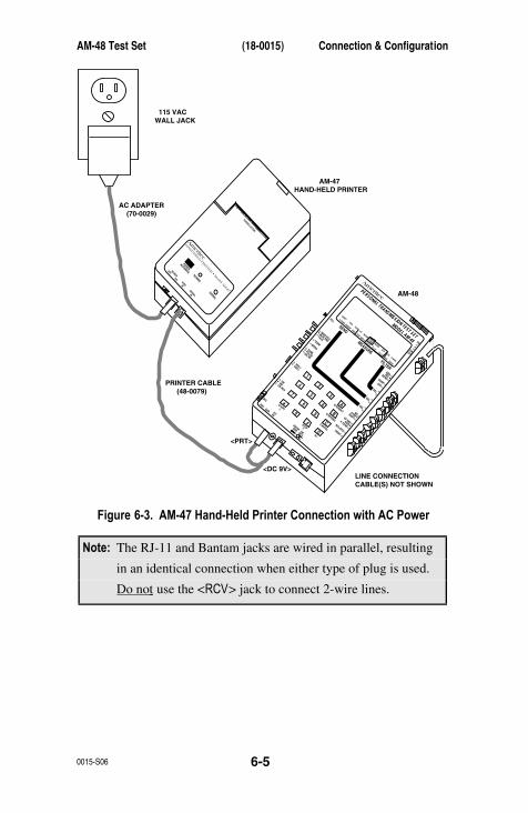
AM-48 Test Set (18-0015) Connection & Configuration
0015-S06 6-5
Ameritec
PERSONAL TRANSMISSION TEST SET
MODEL AM-48
SEND
MEASURE
FILTER
ON
ABSRELSEND
ON/OFF
∇
∇
∇
DAMP ∇ ∇OFF
SEL
900Ω600Ω
∇∇
∇
SEL
∇
∇
SEL
∇
∇
3KC-MSG
15KPROG
QUIET1004
VARPAR L/F
PAR
3 TONESWEEP
NOISE
NOISES/N
HOLDTONE
IMPLSØJTR
JTRTRANS
∇∆ •
•
MON RCV
MON SNDTALK
∇
TERM
∇
BRDG
∇
∇•
4W•
TONEPULSEON HK
∇∇•
MFDTMFSHIFT
ETR/NEXTETR/PREV
CANCEL
STOP
START
4W/2WSND 4WRCV +/-
∇
∇
∇
∇
∇
2W4W REV
MIC
VOL
PRTEAR DC9V
∇
∇
∇
•SF SKPNORX TONE
∇
RCL/STO ∇ ∇
•PRINT ∇
2
1
A
35
4
B
68
7
C
90
*
D
#
PAPER CUTTER
Ameritec
HAND-H
ELD PRINTER • Model AM
-47
PAPERADVANCE
POWER
SIGNAL
POWER
OFF ON9VDCIN
SIGNALIN
115 VACWALL JACK
AC ADAPTER (70-0029)
AM-47HAND-HELD PRINTER
AM-48
PRINTER CABLE (48-0079)
<PRT>
<DC 9V>LINE CONNECTIONCABLE(S) NOT SHOWN
Figure 6-3. AM-47 Hand-Held Printer Connection with AC Power
Note: The RJ-11 and Bantam jacks are wired in parallel, resulting
in an identical connection when either type of plug is used.
Do not use the <RCV> jack to connect 2-wire lines.
Connection & Configuration (18-0015) AM-48 Test Set
0015-S066-6
AM-48 Interface with Line Connections . The position of Switch 10
(Figure 3-5) determines the connection of the AM-48 internal
circuitry to the 2-wire or 4-wire lines. The connections for the
different settings of Switch 10 are listed below:
<2W> Connects the internal measurement circuitry to the
signal generator across the 2-wire line at the <SND>
jack. The signal generator source impedance 600Ω or
900Ω (determined by Switch 11) terminates the line in
all signal generator modes except QUIET. In QUIET
mode, the line will be terminated only if Switch 13 is
set to <TERM>. Note that the < RCV > jack is not used
to connect to 2-wire lines .
<4W> Connects the internal measurement circuitry to the
<RCV> pair, and the internal signal generator to the
<SND> pair.
<4W REV> Send and receive pairs (as defined above) are reversed.
See ¶6.4 and 6.5 for details about line termination impedance.
AM-48 is Polarity Insensitive . It does not matter which way the Send
pair or Receive pair of contacts are connected. The Send <SND> T
and R can be interchanged without affecting the measurement. The
Receive <RCV> T1 and R1 may also be switched without changing
the measurement.
For example, in Figure 5-1, which shows the loopback connections
for self-test, the connections could be changed as indicated below:
Figure 5-1 Connections Alternate Connections
RED (R) to BLACK (R1)GREEN (T) to YELLOW (T1)
RED (R) to YELLOW (T1)GREEN (T) to BLACK (R1)
AM-48 Test Set (18-0015) Connection & Configuration
0015-S06 6-7
In general:
1. For 4-wire
a) Use the <SND> T and R (connecting either way) for
the Send contacts
b) Use the <RCV> T1 and R1 (connecting either way) for
the Receive contacts
2. For 2-wire, use <2W> T and R (connected either way). These
contacts are the same as <SND> for 4-wire.
6.4 600Ω/900Ω Line Termination ImpedancesIt is important that the line(s) be properly terminated with a matching
impedance. This paragraph gives instructions for terminating lines
with 600Ω or 900Ω impedance. To terminate lines with impedance
other than 600Ω or 900Ω connect the Ameritec Impedance Adapter
as per ¶6.5.
To terminate the line(s) correctly with 600Ω or 900Ω:
1. Choose either terminate or bridge mode:
a) Set Switch 13 to <TERM>, terminate mode, or
b) Set Switch 13 to <BRDG>, bridge mode, and terminate
the line with some other device (such as a modem) of
proper impedance.
2. Regardless of the method of termination, set Switch 11 to
<600Ω> or <900Ω> to match the impedance of the line.
Note: An incorrect Switch 11 setting results in about 1.8 dB error
in level and noise readings.
Connection & Configuration (18-0015) AM-48 Test Set
0015-S066-8
Switch 13 Settings . The connections for the settings of Switch 13 are
listed below:
<TERM> Receive line terminated with a resistive impedance as
selected by Switch 11.
<BRDG> Receive line unterminated and bridged only with the
impedance of the measurement circuitry (>25KΩ) across
the receive pair.
Note: In 2-wire mode, the signal generator source impedance will
terminate the line with 600Ω or 900Ω with Switch 13 in
either <TERM> or <BRDG>. However, if SEND is in QUIET
mode, Switch 13 will be able to function. In 2-wire QUIET
send mode, setting Switch 13 to <BRDG> will disconnect the
signal generator from the send pair and the send pair source
impedance will be >25KΩ. There will be an error of 6 dB if
<BRDG> is incorrectly selected when the line should be
terminated with <TERM>.
Switch 11 Settings . The connections for the settings of Switch 11 are
listed below:
<600Ω> 600Ω applied across the Receive pair when Switch 13 is
set to <TERM>.
Send pair source impedance set at 600Ω.
<900Ω> 900Ω applied across the Receive pair when Switch 13 is
set to <TERM>.
Send pair source impedance set at 900Ω.

AM-48 Test Set (18-0015) Connection & Configuration
0015-S06 6-9
6.5 Impedance AdapterThe Impedance Adapter (24-0005) is used:
1. To match the AM-48 to a user interface of impedance other than
600Ω or 900Ω .
2. To match 4-wire split impedances .
See Figure 3-10 for an illustration of the Impedance Adapter; Figure
9-2 is the schematic diagram of the Impedance Adapter.
The Impedance Adapter is used to adapt the AM-48 to impedances of
75Ω, 135Ω, 150Ω, or 1200Ω. For example, high speed digital lines
typically have impedances of 75Ω, 135Ω, or 150Ω. A “THRU”
setting on the Impedance Adapter makes a straight through
connection resulting in a 600Ω or 900Ω termination inside the
AM-48.
To use the AM-48 with the Impedance Adapter:
1. Set AM-48 Switch 11 to <600Ω> and Switch 13 to <BRDG>.
2. Plug the Impedance Adapter into the AM-48 modular jack.
3. Plug a modular line cable into the jack on the Impedance
Adapter.
4. Connect the line cable to the 2-wire or 4-wire line per Figure 6-1
or 6-2.
5. Turn knob(s) on the Impedance Adapter to match the impedance
of the line:
a) For 2-wire, use only the upper knob.
b) For 4-wire, set the upper knob to match the Send pair
impedance and the lower knob to match the Receive
pair impedance.
Connection & Configuration (18-0015) AM-48 Test Set
0015-S066-10
Note: The reading on the AM-48 display needs to be corrected
when the Impedance Adapter is used; see ¶7.41 for
instructions.
6.6 ConfigurationsThere are three (3) basic AM-48 configurations to test 2-wire and 4-
wire telephone and data communication lines:
1. End-to-end - requiring two (2) AM-48’s
2. Loopback
3. Testing with responders
This paragraph describes the different configurations, explains how
they are used, and discusses the advantages and disadvantages.
Note: End-to-end and responder testing applies to either 2-wire or
4-wire. Loopback testing only applies to 4-wire.
End-to-end Testing . Measurements on telephone transmission lines
are usually made by applying an appropriate signal at one end of the
transmission line and then measuring the results at the other end of
the line. This configuration requires a test set at each end of the line
and is called “end-to-end” testing.
Figure 6-4 shows a 4-wire end-to-end configuration, making
measurements over a telephone network that normally connects two
(2) modems. Each AM-48 both sends and receives signals, sending a
signal over the <SND> pair of lines and measuring the signal received
over the <RCV> pair of lines.
End-to-end testing can also be done over 2-wire lines. The AM-48
on one end sends a signal, and the AM-48 on the other end measures
the received signal.
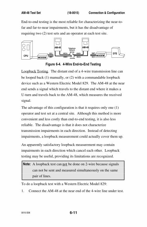
AM-48 Test Set (18-0015) Connection & Configuration
0015-S06 6-11
End-to-end testing is the most reliable for characterizing the near-to-
far and far-to-near impairments, but it has the disadvantage of
requiring two (2) test sets and an operator at each test site.
CPUDTERCV
RCVXMIT
XMIT
<SND>
<RCV> <SND>
<RCV>
AM-48 AM-48
MODEMMODEM
TelephoneNetwork
Figure 6-4. 4-Wire End-to-End Testing
Loopback Testing . The distant end of a 4-wire transmission line can
be looped back (1) manually, or (2) with a commandable loopback
device such as a Western Electric Model 829. The AM-48 at the near
end sends a signal which travels to the distant end where it makes a
U-turn and travels back to the AM-48, which measures the received
signal.
The advantage of this configuration is that it requires only one (1)
operator and test set at a central site. Although this method is more
convenient and less costly than end-to-end testing, it is also less
reliable. The disadvantage is that it does not characterize
transmission impairments in each direction. Instead of detecting
impairments, a loopback measurement could actually cover them up.
An apparently satisfactory loopback measurement may contain
impairments in each direction which cancel each other. Loopback
testing may be useful, providing its limitations are recognized.
Note: A loopback test can not be done on 2-wire because signals
can not be sent and measured simultaneously on the same
pair of lines.
To do a loopback test with a Western Electric Model 829:
1. Connect the AM-48 at the near end of the 4-wire line under test.
Connection & Configuration (18-0015) AM-48 Test Set
0015-S066-12
2. With Switch 8 (Figure 3-5), momentarily press <X TONE> to
send a 2713 Hz tone over the <SND> line. This will trip the
distant Model 829 into loopback.
3. Send the desired test signal with the AM-48 and make the
desired measurement of the looped-back signal.
4. After testing is finished, momentarily press <X TONE> to restore
the Model 829 to its normal, transparent state.
Testing with Responders . The use of multi-function responders
supplies most of the advantages of end-to-end testing with the added
advantage of not requiring an AM-48 at the far end of the system.
This configuration is similar to loopback testing except that the
responder can generate signals in addition to looping back. Unlike a
dedicated loopback device, responders can be used in 2-wire far-to-
near testing.
On 4-wire circuits, a DTMF commandable responder, such as the
Ameritec Model AM3-4, may be placed permanently at the distant
modem where it remains transparent until commanded by DTMF
signals sent from the AM-48 at the central site. In addition to
performing loopback, the responder can send various tones, allowing
for far-to –near tests as well as loopback tests.
EXAMPLE: 4-wire far-to-near and loopback tests for level and
frequency with an Ameritec AM3-4A or AM3-4B Responder:
1. Connect an AM-48 to the near end of a 4-wire facility and an
Ameritec Model AM3-4A or AM3-4B Responder at the far end.
A typical configuration is illustrated in Figure 6-5.
2. Use the AM-48 keypad to send the appropriate DTMF command
sequence to command the responder into milliwatt mode
(responder will generate 1004 Hz, 0 dBm signal). Measure the
received signal and note the level and frequency.
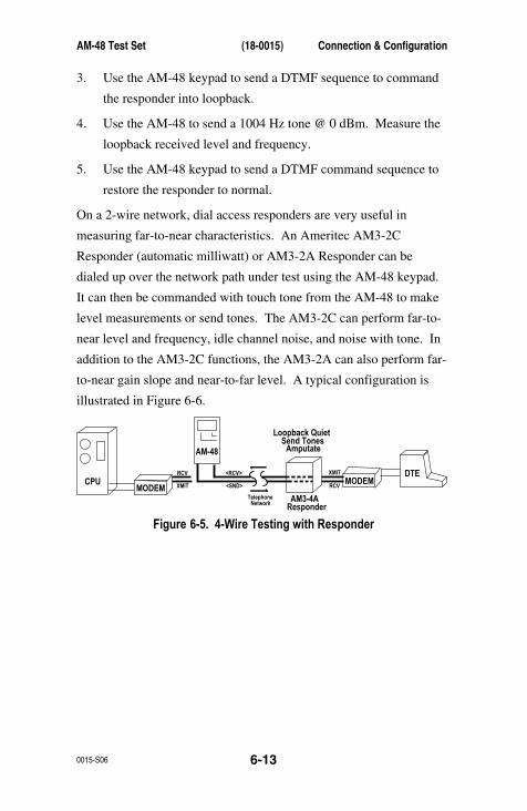
AM-48 Test Set (18-0015) Connection & Configuration
0015-S06 6-13
3. Use the AM-48 keypad to send a DTMF sequence to command
the responder into loopback.
4. Use the AM-48 to send a 1004 Hz tone @ 0 dBm. Measure the
loopback received level and frequency.
5. Use the AM-48 keypad to send a DTMF command sequence to
restore the responder to normal.
On a 2-wire network, dial access responders are very useful in
measuring far-to-near characteristics. An Ameritec AM3-2C
Responder (automatic milliwatt) or AM3-2A Responder can be
dialed up over the network path under test using the AM-48 keypad.
It can then be commanded with touch tone from the AM-48 to make
level measurements or send tones. The AM3-2C can perform far-to-
near level and frequency, idle channel noise, and noise with tone. In
addition to the AM3-2C functions, the AM3-2A can also perform far-
to-near gain slope and near-to-far level. A typical configuration is
illustrated in Figure 6-6.
CPUDTERCV
RCVXMIT
XMIT
<SND>
<RCV>
AM-48
AM3-4AResponder
TelephoneNetwork
Loopback QuietSend Tones
Amputate
MODEMMODEM
Figure 6-5. 4-Wire Testing with Responder
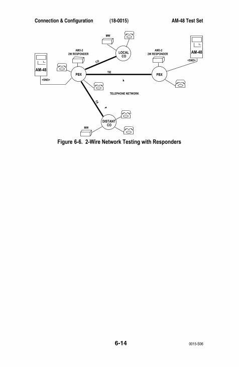
Connection & Configuration (18-0015) AM-48 Test Set
0015-S066-14
LOCALCO
AM-48
AM-48
PBX PBX
DISTANTCO
AM3-22W RESPONDER
TELEPHONE NETWORK
AM3-2
MW
<SND>
TIE
CO
FX
<SND>
MW
2W RESPONDER
Figure 6-6. 2-Wire Network Testing with Responders

AM-48 Test Set (18-0015) Operating Instructions
0015-S07 7-1
7. OPERATING INSTRUCTIONS
Note: Set up the AM-48 per Section 6 before performing
operations in this section.
7.1 IntroductionThe AM-48 operating instructions in this section are divided into five
(5) major subjects and associated paragraphs as listed below:
7.2 General Instructions and Notes
7.3 General Operating Notes
7.4 Figure Format
7.5 General Switch Setup
7.6 Multiple Use of Keys
7.7 Memory
7.8 General Procedure to Set New Parameter Values
7.9 Send (Generator) Modes and Parameter Settings
7.10 Type of Send Signals
7.11 Send Quiet
7.12 Set Parameters from Quiet Display
7.13 Send Momentary Variable Tones
7.14 Send 1004 Hz
7.15 Send Continuous Variable Tone
7.16 Send 3-Tone Slope
7.17 Send Variable Sweep
7.18 Send PAR Waveform
7.19 Send Momentary 2713 Hz Tone
7.20 General Measure Mode Notes
7.21 Accuracy of Measurements
7.22 Absolute and Relative Measurements
7.23 Special Measurement Requirements
7.24 Timed Tests
Operating Instructions (18-0015) AM-48 Test Set
0015-S077-2
7.25 Measure Modes and Parameter Settings
7.26 Measure Level and Frequency
7.27 Measure Noise
7.28 Measure PAR
7.29 Measure Impulse Noise
7.30 Measure Notched Noise
7.31 Measure S.N Ratio
7.32 Measure Phase Jitter
7.33 Measure Amplitude Jitter
7.34 Measure Transients (Impulse Noise, Notched Noise,
Phase Hits, Gain Hits, and Dropouts)
7.35 Miscellaneous Operations
7.36 Store and Recall
7.37 Dialing
7.38 Talking
7.39 Printing
7.40 Auto Study Result Save
7.41 Impedance Adapter Measurement Corrections
7.42 Auto Calibrate
It is assumed in this section that the user is familiar with basic
AM-48 operation, having followed the self-test instructions of
Section 5. Instead of step-by-step procedures with full details, the
instructions refer to the figures, which summarize the information
needed to perform a test.
Read the general notes in ¶7.2 thru 7.10 and 7.20 thru 7.24 before
going to specific operating instructions.
AM-48 Test Set (18-0015) Operating Instructions
0015-S07 7-3
7.2 General Instructions and Notes¶7.3 thru 7.8 cover general instructions and notes. These paragraphs
should be read before doing a specific test or operation.
7.3 General Operating NotesKeys . Do not be afraid to experiment with the keys. The AM-48 will
not accept an “illegal” or meaningless keystroke. If an out-of-
tolerance value is entered in a user-programmable variable field, the
display will default to an acceptable value.
Displays .
1. The units of measurement appear at the top of the display, above
the value. Time and count units are not shown, but are given in
the table associated with the corresponding display.
2. Display decimal points will flash when batteries are low.
3. Displays of “OVER” or “UNDR” indicate the signal being
monitored is too high or low to be read.
4. Depending on the mode, there may be multiple displays through
which one can scroll. All displays accessible form each mode
are shown in the figures.
5. To quickly go to the initial display from another display in a
scroll, momentarily exit and then re-enter the same mode by
moving the cursor. See the example in ¶5.7.
Check List . Go through the following check list to cover important
points while performing any operation:
1. Look at the cursor positions on the menus. These indicate what
SEND and MEASURE mode is selected and what noise-weighting
filter is selected.
Operating Instructions (18-0015) AM-48 Test Set
0015-S077-4
2. Note the color-coding and framing of the cursor menus and use
these to determine if a filter is needed (orange functions) or a
holding tone is needed (within the rectangle) for the present
position of the cursors. See ¶3.7 and 7.23 for explanation of
menu framing.
3. Note the setting of Switch 2, the Display Select Switch. This
will indicate what is being viewed on the display. <ABS> or
<REL> indicate that the display is viewing the MEASURE mode;
while <SEND> indicates the display is viewing the SEND mode.
4. Note the setting of Switch 7. This indicates whether the
keyboard is connected to dial (<DTMF> or <MF>) or to operate
the auxiliary functions (<SHIFT>).
7.4 Figure FormatFigures 7-1 thru 7-9 show the display(s) which can be accessed from
the indicated SEND or MEASURE mode. The position of the menu
cursor, the necessary switch settings, and other pertinent information
is indicated in each figure. A detailed description of the arrangement
of the figures is listed below.
1. The display fields are shown with three (3) types of characters.
The characters are illustrated at the bottom of some figures in a
table labeled “DISPLAY CHARACTER CODE”. The meanings of
the characters are:
a) Solid : These letters and numbers are fixed and will
always appear just as they are shown. They are
abbreviations for the names of the parameters.
AM-48 Test Set (18-0015) Operating Instructions
0015-S07 7-5
b) Cross-hatched : These characters represent values that
are variable but cannot be changed by the user from
the display in which they are shown. In the SEND
modes these indicate the level and frequency being
sent; in the MEASURE mode, they give the measured
values.
c) Plain : These characters represent parameter values
that are variable and can be changed by the user from
the display in which they are shown.
2. Next to each display is a table of information and instructions
which apply to the adjacent display. The middle column of the
table gives the range of acceptable values to enter for a variable
parameter or the range of values that can be measured.
3. The SEND or MEASURE cursor setting is shown darkened on the
menu just as it appears at the bottom of the AM-48 display.
There are always three (3) cursors in view, although only one (1)
is shown in each of the figures. The positions of the other two
(2) cursors will depend upon the test configuration and setup.
4. The switch settings are indicated next to the location of the
switches in the illustration of the AM-48 at the bottom of the
figure. Only the necessary switch settings for the test under
consideration are shown. Set the other switches as appropriate,
according to the test configuration and setup.
5. The notes on the left at the bottom of the figures relate to the
displays. The notes on the right relate to the switches and
keyboard.
Operating Instructions (18-0015) AM-48 Test Set
0015-S077-6
6. At the bottom of some figures, an alternate display(s) is
illustrated, e.g., “OVER” or “UNDR”, which may be displayed to
call attention to an out-of-tolerance condition.
7.5 General Switch SetupSee ¶3.5 for a summary of the use of each switch. Refer to Figure
3-5 for switch identification number (see ¶3.2). Follow the
guidelines below for proper switch setup.
1. Make connections and set Switches 10, 11, and 13 per the line
interface. See ¶6.3 thru 6.5 for details.
2. Connect and turn on power with Switch 1 per Section 4.
3. Switch 2, Display Select, determines what appears on the
display. Set Switch 2 to the desired position:
a) <ABS> to view MEASURE display (see ¶7.22 for use of<REL> position).
b) <SEND> to view SEND display
4. Use Switches 5 and 6 to set the display cursor to the desired
SEND and MEASURE modes, and Switch 4 to select a noise-
weighting filter, if required (see Table 7-5).
5. Set Switch 7 to <SHIFT> to enable auxiliary keyboard functions
to:
a) Scroll through multiple displays
b) Use keyboard to change a parameter value
c) Send momentary user-programmed tone fromkeyboard in QUIET mode
d) Do Store/Recall
e) Run a transient test
f) Do auto calibrate
Leave Switch 7 in <SHIFT> except when dialing.

AM-48 Test Set (18-0015) Operating Instructions
0015-S07 7-7
6. Use Switches 3, 14, and 15 to connect a speaker or earphone to
the desired monitoring point and adjust volume. As a rule, leave
Switch 3 <OFF>.
7. Leave Switch 8 in <NOR> unless it is desired to avoid
transmission of tones in the signaling frequency band (in which
case, set to <SF SKIP>).
8. Use Switch 9 as required to Store and Recall setups or output
information to the Printer port. See ¶7.36 and 7.39.
9. Leave Switch 12 in <ON HK> except to go off-hook on 2-wire
dial access lines. <TONE> and <PULSE> are off-hook positions
and connect a 200Ω DC short across T and R.
Display Damping Switch . Set Switch 3 to <OFF> for a normal
display update of four (4) times per second, or to <DAMP> to slow the
display update to two (2) times per second.
Switch 3 also affects the monitor point of the speaker. Refer to the
upper part of Figure 9-1 with the descriptions below:
1. With Switch 14 set to <MON RCV> and Switch 3 set to <OFF>,
the speaker monitors the signal on the <RCV> jack (T1, R1) for
4-wire operation.
2. With Switch 14 set to <MON RCV> and Switch 3 set to <DAMP>,
the speaker monitors the received signal (from T1, R1 in 4-wire
operation, or T, R in 2-wire operation) at a point following the
noise weighting filter, notch filter (if in use), and auto-ranging
amplifiers. This is particularly useful for audibly monitoring the
residual noise in notched noise and S/N ratio measurements.
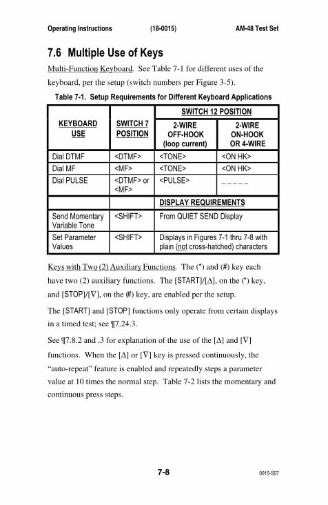
Operating Instructions (18-0015) AM-48 Test Set
0015-S077-8
7.6 Multiple Use of KeysMulti-Function Keyboard . See Table 7-1 for different uses of the
keyboard, per the setup (switch numbers per Figure 3-5).
Table 7-1. Setup Requirements for Different Keyboard Applications
SWITCH 12 POSITION
KEYBOARDUSE
SWITCH 7POSITION
2-WIREOFF-HOOK
(loop current)
2-WIREON-HOOKOR 4-WIRE
Dial DTMF <DTMF> <TONE> <ON HK>
Dial MF <MF> <TONE> <ON HK>
Dial PULSE <DTMF> or<MF>
<PULSE> _ _ _ _ _
DISPLAY REQUIREMENTS
Send MomentaryVariable Tone
<SHIFT> From QUIET SEND Display
Set ParameterValues
<SHIFT> Displays in Figures 7-1 thru 7-8 withplain (not cross-hatched) characters
Keys with Two (2) Auxiliary Functions . The (*) and (#) key each
have two (2) auxiliary functions. The [START]/[∆], on the (*) key,
and [STOP]/[∇], on the (#) key, are enabled per the setup.
The [START] and [STOP] functions only operate from certain displays
in a timed test; see ¶7.24.3.
See ¶7.8.2 and .3 for explanation of the use of the [∆] and [∇]
functions. When the [∆] or [∇] key is pressed continuously, the
“auto-repeat” feature is enabled and repeatedly steps a parameter
value at 10 times the normal step. Table 7-2 lists the momentary and
continuous press steps.
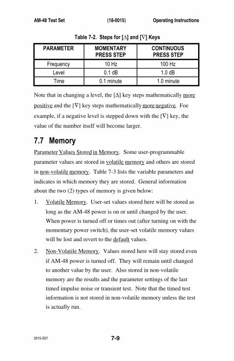
AM-48 Test Set (18-0015) Operating Instructions
0015-S07 7-9
Table 7-2. Steps for [∆] and [∇] Keys
PARAMETER MOMENTARYPRESS STEP
CONTINUOUSPRESS STEP
Frequency 10 Hz 100 Hz
Level 0.1 dB 1.0 dB
Time 0.1 minute 1.0 minute
Note that in changing a level, the [∆] key steps mathematically more
positive and the [∇] key steps mathematically more negative . Foe
example, if a negative level is stepped down with the [∇] key, the
value of the number itself will become larger.
7.7 MemoryParameter Values Stored in Memory . Some user-programmable
parameter values are stored in volatile memory and others are stored
in non-volatile memory . Table 7-3 lists the variable parameters and
indicates in which memory they are stored. General information
about the two (2) types of memory is given below:
1. Volatile Memory . User-set values stored here will be stored as
long as the AM-48 power is on or until changed by the user.
When power is turned off or times out (after turning on with the
momentary power switch), the user-set volatile memory values
will be lost and revert to the default values.
2. Non-Volatile Memory . Values stored here will stay stored even
if AM-48 power is turned off. They will remain until changed
to another value by the user. Also stored in non-volatile
memory are the results and the parameter settings of the last
timed impulse noise or transient test. Note that the timed test
information is not stored in non-volatile memory unless the test
is actually run.
Operating Instructions (18-0015) AM-48 Test Set
0015-S077-10
In order to allow the transfer of timed test information into non-
volatile memory, the AM-48 power will not time-out during a
timed study. The time-out timer restarts at the end of a timed
study.
Level Display . There is only one level setting and it is stored in
volatile memory. For convenience, the level display that shows this
value can be accessed from any SEND display. The level display is
always the second display in the scroll. To access the level display:
1. Set Switch 2 to <SEND>.
2. Set Switch 7 to <SHIFT>.
3. Rock Switch 6 to select any SEND mode.
4. Press [ETR/NEXT]
5. Level display will appear.
Remember that when the level value is changed, it changes the level
for all SEND signals, except for dialed tones (see ¶7.12.3 for
instructions to set touch tone level). When power is turned off, the
send level always defaults to 00.0 dBm. The level for dialed tones,
however, is stored in non-volatile memory.
Store/Recall . Up to 10 test setups, including parameter values, can be
stored in non-volatile memory. A stored test setup can be recalled,
avoiding the need to set cursors and re-enter parameter values for a
routine test. See ¶7.36 for instructions.
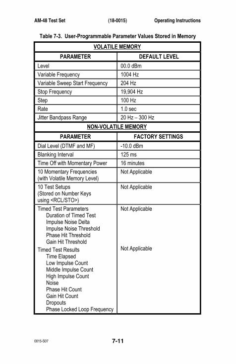
AM-48 Test Set (18-0015) Operating Instructions
0015-S07 7-11
Table 7-3. User-Programmable Parameter Values Stored in Memory
VOLATILE MEMORY
PARAMETER DEFAULT LEVEL
Level 00.0 dBm
Variable Frequency 1004 Hz
Variable Sweep Start Frequency 204 Hz
Stop Frequency 19,904 Hz
Step 100 Hz
Rate 1.0 sec
Jitter Bandpass Range 20 Hz – 300 Hz
NON-VOLATILE MEMORY
PARAMETER FACTORY SETTINGS
Dial Level (DTMF and MF) -10.0 dBm
Blanking Interval 125 ms
Time Off with Momentary Power 16 minutes
10 Momentary Frequencies(with Volatile Memory Level)
Not Applicable
10 Test Setups(Stored on Number Keysusing <RCL/STO>)
Not Applicable
Timed Test ParametersDuration of Timed TestImpulse Noise DeltaImpulse Noise ThresholdPhase Hit ThresholdGain Hit Threshold
Timed Test ResultsTime ElapsedLow Impulse CountMiddle Impulse CountHigh Impulse CountNoisePhase Hit CountGain Hit CountDropoutsPhase Locked Loop Frequency
Not Applicable
Not Applicable
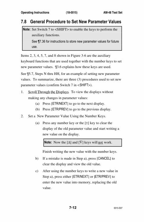
Operating Instructions (18-0015) AM-48 Test Set
0015-S077-12
7.8 General Procedure to Set New Parameter Values
Note: Set Switch 7 to <SHIFT> to enable the keys to perform the
auxiliary functions.
See ¶7.36 for instructions to store new parameter values for future
use.
Items 2, 3, 4, 5, 7, and 8 shown in Figure 3-6 are the auxiliary
keyboard functions that are used together with the number keys to set
new parameter values. ¶3.6 explains how these keys are used.
See ¶5.7, Steps N thru HH, for an example of setting new parameter
values. To summarize, there are three (3) procedures used to set new
parameter values (confirm Switch 7 in <SHIFT>).
1. Scroll Through the Displays . To view the displays without
making any changes in parameter values:
(a) Press [ETR/NEXT] to go to the next display.
(b) Press [ETR/PREV] to go to the previous display.
2. Set a New Parameter Value Using the Number Keys.
(a) Press any number key or the [±] key to clear the
display of the old parameter value and start writing a
new value on the display.
Note: Now the [∆] and [∇] keys will not work.
Finish writing the new value with the number keys.
b) If a mistake is made in Step a), press [CANCEL] to
clear the display and view the old value.
c) After using the number keys to write a new value in
Step a), press either [ETR/NEXT] or [ETR/PREV] to
enter the new value into memory, replacing the old
value.
AM-48 Test Set (18-0015) Operating Instructions
0015-S07 7-13
Note: Now [CANCEL] will not work.
d) Use Step1 to go to another display.
3. Set a New Parameter Value Using the [∆] and [∇] Keys.
a) Press [∆] and/or [∇] to step the displayed parameter
value up or down to a new value. To step in
increments 10 times the normal increment, hold the
key down continuously. See Table 7-2 for step values.
The new value displayed is entered directly into
memory, replacing the old value.
b) The [CANCEL] key will not work here because the new
value directly replaces the old value in memory.
c) [±] can not be used to change the sign because it will
clear the display (see Step 2a).
d) Use Step1 to go to another display.
7.9 Send (Generator) Modes and Parameter SettingsParagraphs 7.10 thru 7.19 discuss the SEND modes.
Note: For all SEND modes, set Switch 8 to <SF SKIP> to prevent
sending tones in the signaling band of 2450 Hz to 2750 Hz
(2130 Hz to 2430 Hz for AM-48E). Set Switch 8 to
<NOR> to allow all frequencies to be sent.
7.10 Types of Send SignalsThe AM-48 Send signals can be classified according to their
duration. The three (3) types of Send signals are:
1. Momentary
2. Continuous
3. Stepped (Slope and Sweep)
Operating Instructions (18-0015) AM-48 Test Set
0015-S077-14
To send a variable momentary tone, set the SEND cursor to QUIET and
set the level and frequency per instructions in ¶7.12.1 and 7.12.2.
Send the frequency from the QUIET SEND display by pressing the
number to which the tone is assigned. Momentarily press Switch 8 to
<X TONE> to send momentary 2713 Hz tone (¶7.19).
To send a variable continuous tone, set the SEND cursor to VAR and
set the desired level and frequency per ¶7.15.
To send continuous 1004 Hz, set the SEND cursor to 1004 (¶7.14). To
send continuous PAR, set the SEND cursor to PAR (¶7.18).
To send a pre-programmed set of slope frequencies, set the SEND
cursor to 3TONE (SLOPE for the AM-48E) (see ¶7.16).
To send variable sweep set the SEND cursor to SWEEP (¶7.17).
7.11 Send Quiet1. See Figure 7-1. Set switches per the SWITCH SETUP illustration
and the SEND cursor per the menu illustration.
2. A Quiet termination display will appear, “_ _ _ _ _ _ _ _”,
confirming that the AM-48 is quiet terminated.
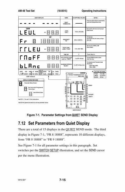
AM-48 Test Set (18-0015) Operating Instructions
0015-S07 7-15
AmeritecPERSONAL TRANSMISSION TEST SET
MODEL AM-48
SEND MEASURE FILTER
ON
ABSREL
SEND
ON/OFF
∇
∇
∇
DAMP
∇
∇
OFF
SEL
900Ω600Ω
∇
∇
∇
SEL
∇
∇
SEL
∇
∇
3K C-MSG
15K PROG
QUIET 1004 VAR
PAR
L/F
PAR3 TONE SWEEP
NOISE NOISE S/NHOLDTONE
IMPLS ØJTR JTR TRANS∇∆
•
•
MON RCVMON SNDTALK
∇
TERM∇
BRDG
∇∇•
4W•
TONEPULSEON HK
∇
∇•
MFDTMFSHIFT
ETR/NEXT
ETR/PREV
CANCEL
STOPSTART
4W/2WSND
4WRCV
+/-
∇
∇
∇
∇
∇
2W
4W REV
MIC
VOL
PRT EARDC9V
∇
∇
∇
•
SF SKPNOR
X TONE
∇
RCL/STO
∇
∇
•
∇
21 A3
54 B6
87 C9
0* D#
Set QUIET
<SEND>
SWITCH SETUP
<SHIFT>
DBM
HZ
3K C-MSG
15K PROG
QUIET 1004 VAR
PAR
L/F
PAR3 TONE SWEEP
NOISE NOISE S/NHOLDTONE
IMPLS ØJTR JTR TRANS∇∆
QUIET darkened
•
•
QUIET DISPLAYS NAME ACCEPTABLE VALUES
FACTORY SETTINGS
TTLEVTMOFFBLANC
-10.0 dBm16 minutes125 ms
NOTES
QUIETTERMINATION
10.0 to -50.0 dBm
Press key ([0] to [9]) to momentarilysend user-programmed tone.
Set level for all tones sent (exceptdialed tones.
10 displays.
[0] to [9].Set frequencies for tones on keys
Set level for DTMF or MFtones dialed.
Power stays on.
Unused AM-48 powers downafter this time.
For Impulse and Transient testsStandards:
143ms Bell 41009125ms IEEE
200 to 19,999 Hz
7.0 to -50.0* dBm
LEVEL"LEVL"
LEVEL "TTLEV"TOUCH TONE
FREQUENCY "FR"
BLANKING INTERVAL "BLANC"
TIME OFF
with momentary power switch on "TMOFF"
0
1 to 255* minutes
1 to 255* millisec (ms)
DISPLAY CHARACTER CODE
Parameter Name (Fixed)
Key from which Programmed
See ¶7.11, 7.12, and 7.13 for instructions.
See ¶7.8 for general procedure to set new parameter values.
User-Entered Value
Tone is Sent
*
Figure 7-1. Parameter Settings from QUIET SEND Display
7.12 Set Parameters from Quiet DisplayThere are a total of 15 displays in the QUIET SEND mode. The third
display in Figure 7-1, “FR 8 18888”, represents 10 different displays,
from “FR 0 18888” to “FR 9 18888”.
See Figure 7-1 for all parameter settings in this paragraph. Set
switches per the SWITCH SETUP illustration, and set the SEND cursor
per the menu illustration.
Operating Instructions (18-0015) AM-48 Test Set
0015-S077-16
1. Set Level (see Figure 7-1 and ¶7.8).
a) Go to “LEVL” display.
b) Set desired level value (default value is 00.0 dBm).
c) New level value is stored in volatile memory.
2. Set Up to 10 Frequencies , sent with number keys from QUIET
display (see Figure 7-1 and ¶7.8).
a) Go to desired “FR” display - - one (1) of 10.
b) The number after “FR” identifies the number key onto
which the frequency is programmed.
c) Set desired frequency value.
d) This value is stored in non-volatile memory.
e) Repeat Steps a) and c) for other frequencies as desired.
3. Set Touch Tone Level (see Figure 7-1 and ¶7.8).
a) Go to “TTLEV” display.
b) Set desired level value for DTMF and MF dialing.
c) Recommended level (factory setting) is –10.0 dBm.
d) This value is stored in non-volatile memory.
4. Set Time Off : operates when power is turned on with the
momentary power switch (see Figure 7-1 and ¶7.8).
a) Go to “TMOFF” display.
b) Set desired time value.
c) This value is stored in non-volatile memory (factory
setting is 16 minutes).
d) This time is when the AM-48 will turn off after the
last key or switch activity, if the unit has been turned
on with the momentary power switch.
AM-48 Test Set (18-0015) Operating Instructions
0015-S07 7-17
e) Note that the AM-48 will not turn itself off if a time of
“0” is set. A time of “0” is not a desirable setting
when using batteries.
5. Set Blanking Interval (see Figure 7-1 and ¶7.8).
a) Go to “BLANC” display.
b) Set desired blanking interval value.
c) This value is stored in non-volatile memory (factory
setting is 125 ms).
d) The meaning of the blanking interval for timed tests is
explained in ¶8.9.
e) Note the Bell and IEEE standard settings listed in
Figure 7-1.
7.13 Send Momentary Variable Tones1. With the switches and cursor set per Figure 7-1, program desired
frequencies on the number keys per ¶7.12.2.
2. The level of the tone sent is the value in the “LEVL” display,
stored in volatile memory (factory setting is 125 ms).
3. Go to the QUIET termination display, “_ _ _ _ _ _ _ _”.
Note: First select “SEND 1004” and then step backwards to select
QUIET termination.
4. Press the appropriate number key; [0], [1], [2], . . . . [9], to send
the desired frequency.
5. The tone will be sent for as long as the key is held down.

Operating Instructions (18-0015) AM-48 Test Set
0015-S077-18
7.14 Send 1004 Hz1. See Figure 7-2. Set switches per the SWITCH SETUP illustration,
and set the SEND cursor per the lower menu illustration.
2. Go to the “LEVL” display and set the desired level value.
AmeritecPERSONAL TRANSMISSION TEST SET
MODEL AM-48
SEND MEASURE FILTER
ON
ABSREL
SEND
ON/OFF
∇
∇
∇
DAMP
∇
∇
OFF
SEL
900Ω600Ω
∇
∇
∇
SEL
∇
∇
SEL
∇
∇
3K C-MSG
15K PROG
QUIET 1004 VAR
PAR
L/F
PAR3 TONE SWEEP
NOISE NOISE S/NHOLDTONE
IMPLS ØJTR JTR TRANS∇∆
•
•
MON RCVMON SNDTALK
∇
TERM∇
BRDG
∇∇•
4W•
TONEPULSEON HK
∇
∇•
MFDTMFSHIFT
ETR/NEXT
ETR/PREV
CANCEL
STOPSTART
4W/2WSND
4WRCV
+/-
∇
∇
∇
∇
∇
2W
4W REV
MIC
VOL
PRT EARDC9V
∇
∇
∇
•
SF SKPNOR
X TONE
∇
RCL/STO
∇
∇
•
∇
21 A3
54 B6
87 C9
0* D#
Set 1004 or VAR
<SEND>
SWITCH SETUP
<SHIFT>
DBM
HZ
HZ
3K C-MSG
15K PROG
QUIET 1004 VAR
PAR
L/F
PAR3 TONE SWEEP
NOISE NOISE S/NHOLDTONE
IMPLS ØJTR JTR TRANS∇∆
VAR darkened
•
•
VARIABLE TONE DISPLAYS NAME ACCEPTABLE VALUES NOTES
VARIABLETONE
10.0 to -50.0 dBm
Send Level and Frequency ofvariable constant tone.
Set level for all tones sent (exceptdialed tones).
constant tones.Set frequency for variable
200 to 19,999 Hz
LEVEL"LEVL"
FREQUENCY "FREQ"
DISPLAY CHARACTER CODE
Parameter Name (Fixed)
Key from which Programmed
See ¶7.8 for general procedure to set new parameter values.
User-Entered Value
Tone is Sent
DBM
HZ
3K C-MSG
15K PROG
QUIET 1004 VAR
PAR
L/F
PAR3 TONE SWEEP
NOISE NOISE S/NHOLDTONE
IMPLS ØJTR JTR TRANS∇∆
1004 darkened
DBM
•
•
•
1004 HZ TONE DISPLAYS NAME ACCEPTABLE VALUES NOTES
"1004" HZ TONE
10.0 to -50.0 dBm
Send Level of 1004 Hzconstant tone.
Set level for all tones sent (exceptdialed tones).LEVEL
"LEVL"
DBM
Figure 7-2. Parameter Settings from 1004 Hz and VAR Tone Send Displays
AM-48 Test Set (18-0015) Operating Instructions
0015-S07 7-19
7.15 Send Continuous Variable Tone1. See Figure 7-2. Set switches per the SWITCH SETUP illustration,
and set the SEND cursor per the lower menu illustration.
2. Go to the “LEVL” display and set the desired level value.
3. Go to the “FREQ” display and set the desired frequency value.
7.16 Send Set of Slope Tones1. See Figure 7-3. Set switches per the SWITCH SETUP illustration,
and set the SEND cursor per the upper menu illustration.
2. Go to the “LEVL” display and set the desired level value.
3. Go to the initial display and note that the frequencies 404 Hz,
1004 Hz, and 2804 Hz (404 Hz, 1004 Hz, 2004 Hz, and 3004 Hz
for AM-48E) are sent in a cycle @ 5 seconds.
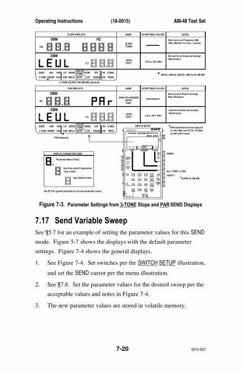
Operating Instructions (18-0015) AM-48 Test Set
0015-S077-20
AmeritecPERSONAL TRANSMISSION TEST SET
MODEL AM-48
SEND MEASURE FILTER
ON
ABSREL
SEND
ON/OFF
∇
∇
∇
DAMP
∇
∇OFF
SEL
900Ω600Ω
∇
∇
∇
SEL
∇
∇
SEL
∇
∇
3K C-MSG
15K PROG
QUIET 1004 VAR
PAR
L/F
PAR3 TONE SWEEP
NOISE NOISE S/NHOLDTONE
IMPLS ØJTR JTR TRANS∇∆
•
•
MON RCVMON SNDTALK
∇
TERM∇
BRDG
∇∇•
4W•
TONEPULSEON HK
∇
∇•
MFDTMFSHIFT
ETR/NEXT
ETR/PREV
CANCEL
STOPSTART
4W/2WSND
4WRCV
+/-
∇
∇
∇
∇
∇
2W
4W REV
MIC
VOL
PRT EARDC9V
∇
∇
∇
•
SF SKPNOR
X TONE
∇
RCL/STO
∇
∇
•
∇
21 A3
54 B6
87 C9
0* D#
Set 3 TONE* or PAR
*SLOPE for AM-48E
<SEND>
SWITCH SETUP
<SHIFT>
DBM
3K C-MSG
15K PROG
QUIET 1004 VAR
PAR
L/F
PAR3 TONE SWEEP
NOISE NOISE S/NHOLDTONE
IMPLS ØJTR JTR TRANS∇∆
PAR darkened
•
•
PAR DISPLAYS NAME ACCEPTABLE VALUES NOTES
PEAK-TO-AVERAGERATIO"PAR"
0.0 to -40.0* dBm
Send Level of Peak-to-AverageRatio Waveform.
*PAR waveform level has range 0.0to -40.0 dBm (not 10.0 to -50 dBm,as with other tones).
LEVEL"LEVL"
DISPLAY CHARACTER CODE
Parameter Name (Fixed)
Key from which Programmed
See ¶7.8 for general procedure to set new parameter values.
User-Entered Value
Tone is Sent
DBM
HZ
3K C-MSG
15K PROG
QUIET 1004 VAR
PAR
L/F
PAR3 TONE SWEEP
NOISE NOISE S/NHOLDTONE
IMPLS ØJTR JTR TRANS∇∆
3 TONE (SLOPE FOR AM-48E) darkened
DBM
•
•
•
SLOPE DISPLAYS NAME ACCEPTABLE VALUES NOTES
SLOPETONES
10.0 to -50.0 dBm
Send Level and Frequency (404,
404 Hz, 1004 Hz, 2004 Hz, 3004 Hz for AM-48E
1004, 2804 Hz* for 5 sec., cyclical).
Set level for all tones sent (exceptdialed tones).
Level for all tones sent (exceptdialed tones).
LEVEL"LEVL"
DBM
*
Figure 7-3. Parameter Settings from 3-TONE Slope and PAR SEND Displays
7.17 Send Variable SweepSee ¶5.7 for an example of setting the parameter values for this SEND
mode. Figure 5-7 shows the displays with the default parameter
settings. Figure 7-4 shows the general displays.
1. See Figure 7-4. Set switches per the SWITCH SETUP illustration,
and set the SEND cursor per the menu illustration.
2. See ¶7.8. Set the parameter values for the desired sweep per the
acceptable values and notes in Figure 7-4.
3. The new parameter values are stored in volatile memory.
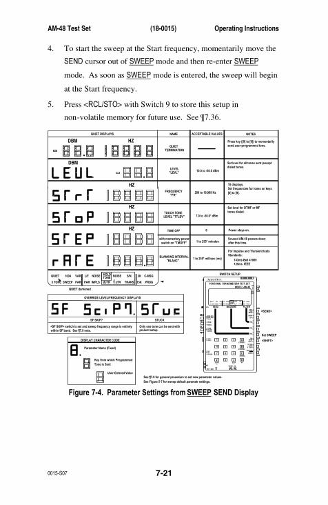
AM-48 Test Set (18-0015) Operating Instructions
0015-S07 7-21
4. To start the sweep at the Start frequency, momentarily move the
SEND cursor out of SWEEP mode and then re-enter SWEEP
mode. As soon as SWEEP mode is entered, the sweep will begin
at the Start frequency.
5. Press <RCL/STO> with Switch 9 to store this setup in
non-volatile memory for future use. See ¶7.36.
AmeritecPERSONAL TRANSMISSION TEST SET
MODEL AM-48
SEND MEASURE FILTER
ON
ABSREL
SEND
ON/OFF
∇
∇
∇
DAMP
∇
∇
OFF
SEL
900Ω600Ω
∇
∇
∇
SEL
∇
∇
SEL
∇
∇
3K C-MSG
15K PROG
QUIET 1004 VAR
PAR
L/F
PAR3 TONE SWEEP
NOISE NOISE S/NHOLDTONE
IMPLS ØJTR JTR TRANS∇∆
•
•
MON RCVMON SNDTALK
∇
TERM∇
BRDG
∇∇•
4W•
TONEPULSEON HK
∇
∇•
MFDTMFSHIFT
ETR/NEXT
ETR/PREV
CANCEL
STOPSTART
4W/2WSND
4WRCV
+/-
∇
∇
∇
∇
∇
2W
4W REV
MIC
VOL
PRT EARDC9V
∇
∇
∇
•
SF SKPNOR
X TONE
∇
RCL/STO
∇
∇
•
∇
21 A3
54 B6
87 C9
0* D#
Set SWEEP
<SEND>
SWITCH SETUP
<SHIFT>
DBM
DBM
HZ
HZ
3K C-MSG
15K PROG
QUIET 1004 VAR
PAR
L/F
PAR3 TONE SWEEP
NOISE NOISE S/NHOLDTONE
IMPLS ØJTR JTR TRANS∇∆
QUIET darkened
•
•
•
QUIET DISPLAYS NAME ACCEPTABLE VALUES NOTES
QUIETTERMINATION
10.0 to -50.0 dBm
Press key ([0] to [9]) to momentarilysend user-programmed tone.
Set level for all tones sent (exceptdialed tones.
10 displays.
[0] to [9].Set frequencies for tones on keys
Set level for DTMF or MFtones dialed.
Power stays on.
Unused AM-48 powers downafter this time.
For Impulse and Transient tests
<SF SKIP> switch is set and sweep frequency range is entirelywithin SF band. See ¶7.9 note.
Only one tone can be sent withpresent setup.
Standards:
143ms Bell 41009125ms IEEE
200 to 19,999 Hz
7.0 to -50.0* dBm
LEVEL"LEVL"
LEVEL "TTLEV"TOUCH TONE
FREQUENCY "FR"
BLANKING INTERVAL "BLANC"
TIME OFF
OVERRIDE LEVEL/FREQUENCY DISPLAYS
SF SKIP? STUCK
with momentary power switch on "TMOFF"
0
1 to 255* minutes
1 to 255* millisec (ms)
DISPLAY CHARACTER CODE
Parameter Name (Fixed)
Key from which Programmed
See ¶7.8 for general procedure to set new parameter values.See Figure 5-7 for sweep default parametr settings.
User-Entered Value
Tone is Sent
HZ
HZ
•
•
Figure 7-4. Parameter Settings from SWEEP SEND Display
Operating Instructions (18-0015) AM-48 Test Set
0015-S077-22
7.18 Send PAR Waveform1. See Figure 7-3. Set switches per the SWITCH SETUP illustration,
and set the SEND cursor per the lower menu illustration.
2. Go to the “LEVL” display and set the desired level value.
3. PAR level is limited to the range 00.0 dBm to –40.0 dBm.
4. If the level were above 00.0 dBm or below –40.0 dBm, the PAR
level would default to 00.0 dBm 0r –40.0 dBm, respectively,
while sending PAR. For this case, if no new level value were set
while in the PAR mode, the level value would return to its
previous value after exiting PAR.
7.19 Send Momentary 2713 Hz TonePress <X TONE> with Switch 8 to momentarily send a 2713 Hz tone,
overriding the internal signal generator. This is used to activate
loopback devices. See “ Loopback Testing ” in ¶6.6.
7.20 ¶7.21 thru 7.24 cover general instructions
and Notes for the MEASURE Modes.
7.21 Accuracy of MeasurementsObserve instructions listed here to ensure accurate readings with the
AM-48.
1. Be sure Switch 12 is in <ON HK> except when an off-hook
condition is desired for 2-wire access lines. Switch 12 in
<TONE> or <PULSE> will cause erroneous readings for
measurements on 4-wire circuits.
AM-48 Test Set (18-0015) Operating Instructions
0015-S07 7-23
2. Be sure that Switch 11 is set to match the line impedance.
Generally, <600Ω> matches 4-wire and <900Ω> matches 2-wire.
A wrong Switch 11 setting results in about 1.8 dB error in level
and noise measurements.
3. Use batteries when making low-level noise measurements.
4. For 2-wire measurements (Switch 2 in <ABS> or <REL>), set the
SEND Cursor to QUIET mode; if not, the AM-48 will be
measuring its own generator output in addition to the signal
received from the far end of the line.
5. When using the Impedance Adapter (¶6.5 and 9.3), correct the
measurements per instructions in ¶7.41.
7.22 Absolute and Relative MeasurementsSee ¶8.2 for a discussion of units of measurement, including
Absolute and Relative measurements.
Either an Absolute or Relative measurement can be made with any
level or noise measurement . The choice is made by setting the
Display Switch, Switch 2, to either <ABS> or <REL>. The use of
<ABS> and <REL> is outlined below:
1. Normally, the absolute (<ABS>) setting is used for noise and
level measurements.
2. The <REL> position is used to establish a new zero reference
level. This is useful in tests such as frequency response, where
levels at various frequencies are to be compared with the level at
a reference frequency.
To use <REL>:
1. Start with Switch 2 in <ABS>.

Operating Instructions (18-0015) AM-48 Test Set
0015-S077-24
2. When the desired reference point is established, set Switch 2 to
<REL>.
3. When <REL> is first selected, the display will read “00.0 dB
REL”, meaning that the level or noise reading is now referenced
to the reading that was on the display when <REL> was pressed.
4. Subsequent readings are now referenced to this new zero
reference.
5. To summarize, “REL” means “relative to the last reading before
<REL> was pressed”.
EXAMPLE: Changing from <ABS> to <REL> with a level
measurement.
1. With the MEASURE cursor in L/F and Switch 2 set to <ABS>, a
level of “-17.7 dBm” is displayed.
2. Set Switch 2 to <REL>. The reading is now “00.0 dB REL”.
3. With Switch 2 still in <REL>, the reading changes to “-02.3 dB
REL”. This means that the level is –2.3 dB relative to the
reading just before <REL> was set.
4. The absolute reading would be –17.7 + -2.3 = -20.0 dBm.
7.23 Special Measurement RequirementsCertain measurements require one or more of the following
conditions in order to be valid:
1. 1004 Hz nominal Holding Tone.
2. One (1) of the following noise-weighting filters:
a) C-Message, C-MSG (Psophometric, PSHO for AM-48E)
b) 3 kHz, 3K
c) 15 kHz, 15K
d) Program PROG (Sound-weighted, SWTD for AM-48E)
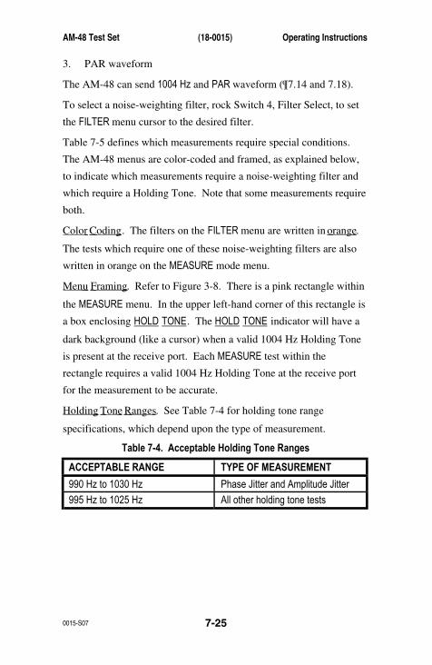
AM-48 Test Set (18-0015) Operating Instructions
0015-S07 7-25
3. PAR waveform
The AM-48 can send 1004 Hz and PAR waveform (¶7.14 and 7.18).
To select a noise-weighting filter, rock Switch 4, Filter Select, to set
the FILTER menu cursor to the desired filter.
Table 7-5 defines which measurements require special conditions.
The AM-48 menus are color-coded and framed, as explained below,
to indicate which measurements require a noise-weighting filter and
which require a Holding Tone. Note that some measurements require
both.
Color Coding . The filters on the FILTER menu are written in orange .
The tests which require one of these noise-weighting filters are also
written in orange on the MEASURE mode menu.
Menu Framing . Refer to Figure 3-8. There is a pink rectangle within
the MEASURE menu. In the upper left-hand corner of this rectangle is
a box enclosing HOLD TONE. The HOLD TONE indicator will have a
dark background (like a cursor) when a valid 1004 Hz Holding Tone
is present at the receive port. Each MEASURE test within the
rectangle requires a valid 1004 Hz Holding Tone at the receive port
for the measurement to be accurate.
Holding Tone Ranges . See Table 7-4 for holding tone range
specifications, which depend upon the type of measurement.
Table 7-4. Acceptable Holding Tone Ranges
ACCEPTABLE RANGE TYPE OF MEASUREMENT
990 Hz to 1030 Hz Phase Jitter and Amplitude Jitter
995 Hz to 1025 Hz All other holding tone tests
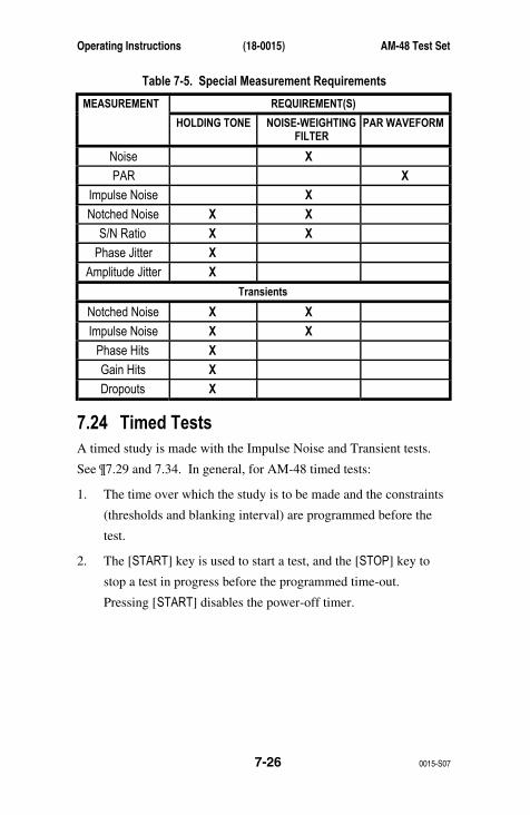
Operating Instructions (18-0015) AM-48 Test Set
0015-S077-26
Table 7-5. Special Measurement Requirements
REQUIREMENT(S)MEASUREMENT
HOLDING TONE NOISE-WEIGHTINGFILTER
PAR WAVEFORM
Noise X
PAR X
Impulse Noise X
Notched Noise X X
S/N Ratio X X
Phase Jitter X
Amplitude Jitter X
Transients
Notched Noise X X
Impulse Noise X X
Phase Hits X
Gain Hits X
Dropouts X
7.24 Timed TestsA timed study is made with the Impulse Noise and Transient tests.
See ¶7.29 and 7.34. In general, for AM-48 timed tests:
1. The time over which the study is to be made and the constraints
(thresholds and blanking interval) are programmed before the
test.
2. The [START] key is used to start a test, and the [STOP] key to
stop a test in progress before the programmed time-out.
Pressing [START] disables the power-off timer.
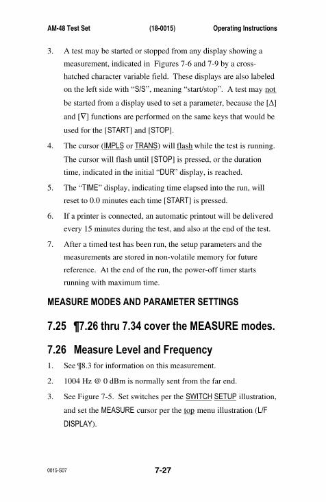
AM-48 Test Set (18-0015) Operating Instructions
0015-S07 7-27
3. A test may be started or stopped from any display showing a
measurement, indicated in Figures 7-6 and 7-9 by a cross-
hatched character variable field. These displays are also labeled
on the left side with “S/S”, meaning “start/stop”. A test may not
be started from a display used to set a parameter, because the [∆]
and [∇] functions are performed on the same keys that would be
used for the [START] and [STOP].
4. The cursor (IMPLS or TRANS) will flash while the test is running.
The cursor will flash until [STOP] is pressed, or the duration
time, indicated in the initial “DUR” display, is reached.
5. The “TIME” display, indicating time elapsed into the run, will
reset to 0.0 minutes each time [START] is pressed.
6. If a printer is connected, an automatic printout will be delivered
every 15 minutes during the test, and also at the end of the test.
7. After a timed test has been run, the setup parameters and the
measurements are stored in non-volatile memory for future
reference. At the end of the run, the power-off timer starts
running with maximum time.
MEASURE MODES AND PARAMETER SETTINGS
7.25 ¶7.26 thru 7.34 cover the MEASURE modes.
7.26 Measure Level and Frequency1. See ¶8.3 for information on this measurement.
2. 1004 Hz @ 0 dBm is normally sent from the far end.
3. See Figure 7-5. Set switches per the SWITCH SETUP illustration,
and set the MEASURE cursor per the top menu illustration (L/F
DISPLAY).
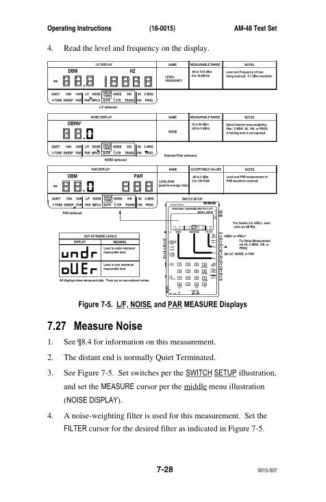
Operating Instructions (18-0015) AM-48 Test Set
0015-S077-28
4. Read the level and frequency on the display.
AmeritecPERSONAL TRANSMISSION TEST SET
MODEL AM-48
SEND MEASURE FILTER
ON
ABSREL
SEND
ON/OFF
∇
∇
∇
DAMP
∇
∇
OFF
SEL
900Ω600Ω
∇
∇
∇
SEL
∇
∇
SEL
∇
∇
3K C-MSG
15K PROG
QUIET 1004 VAR
PAR
L/F
PAR3 TONE SWEEP
NOISE NOISE S/NHOLDTONE
IMPLS ØJTR JTR TRANS∇∆
•
•
MON RCVMON SNDTALK
∇
TERM∇
BRDG
∇∇•
4W•
TONEPULSEON HK
∇
∇•
MFDTMFSHIFT
ETR/NEXT
ETR/PREV
CANCEL
STOPSTART
4W/2WSND
4WRCV
+/-
∇
∇
∇
∇
∇
2W
4W REV
MIC
VOL
PRT EARDC9V
∇
∇
∇
•
SF SKPNOR
X TONE
∇
RCL/STO
∇
∇
•
∇
21 A3
54 B6
87 C9
0* D#
Set L/F, NOISE, or PAR
<ABS> or <REL>*
*For Switch 2 in <REL>, levelunits are dB REL
For Noise Measurement,set 3K, C-MSG, 15K, orPROG
SWITCH SETUP3K C-MSG
15K PROG
QUIET 1004 VAR
PAR
L/F
PAR3 TONE SWEEP
NOISE NOISE S/NHOLDTONE
IMPLS ØJTR JTR TRANS∇∆
PAR darkened
PAR DISPLAY NAME ACCEPTABLE VALUES NOTES
LEVEL/PAR(peak-to-average ratio)
Level and PAR measurement ofPAR waveform received.
OUT-OF-RANGE LEVELS
DISPLAY MEANING
Level is under minimummeasurable level.
Level is over maximum
All displays show merasured data. There are no user-entered values.
measurable level.
HZ
3K C-MSG
15K PROG
QUIET 1004 VAR
PAR
L/F
PAR3 TONE SWEEP
NOISE NOISE S/NHOLDTONE
IMPLS ØJTR JTR TRANS∇∆
L/F darkened
DBM
•
•
L/F DISPLAY NAME MEASURABLE RANGE NOTES
LEVEL/FREQUENCY
Level and Frequency of tonebeing received. 0.1 dBm resolution
-65 to 10.9 dBm0 to 19,999 Hz
DBM PAR
3K C-MSG
15K PROG
QUIET 1004 VAR
PAR
L/F
PAR3 TONE SWEEP
NOISE NOISE S/NHOLDTONE
IMPLS ØJTR JTR TRANS∇∆
NOISE darkenedSelected Filter darkened
DBRN*
•
NOISE DISPLAY NAME MEASURABLE RANGE NOTES
NOISE
Select desired noise-weightingfilter: C-MSG, 3K, 15K, or PROG.A holding tone is not required.
10 to 99 dBrn(-80 to 9 dBm)
-40 to 0 dBm0 to 120 P/AR
Figure 7-5. L/F, NOISE, and PAR MEASURE Displays
7.27 Measure Noise1. See ¶8.4 for information on this measurement.
2. The distant end is normally Quiet Terminated.
3. See Figure 7-5. Set switches per the SWITCH SETUP illustration,
and set the MEASURE cursor per the middle menu illustration
(NOISE DISPLAY).
4. A noise-weighting filter is used for this measurement. Set the
FILTER cursor for the desired filter as indicated in Figure 7-5.

AM-48 Test Set (18-0015) Operating Instructions
0015-S07 7-29
5. Read the noise on the display. Note that the reading will always
be a whole number.
7.28 Measure PAR1. See ¶8.7 for information on this measurement.
2. A PAR waveform must be sent from the far end for this
measurement to be valid.
3. See Figure 7-5. Set switches per the SWITCH SETUP illustration,
and set the MEASURE cursor per the bottom menu illustration
(PAR DISPLAY).
4. Read the level and PAR value on the display. Note that the
readings will always be a whole numbers.
7.29 Measure Impulse Noise
General Information
1. This is a timed test. See ¶7.24.
2. Three (3) noise thresholds are established: low , middle , and
high . There is an equal interval between each threshold called
the delta .
3. The time over which the run is to be made is set, called the
duration .
4. The run is started, and a running count is kept of the number of
noise pulses that exceed each threshold.
5. The run will automatically stop when the duration time is
reached, or the test can be manually stopped at any previous
time.
6. The “TIME” display resets to zero at the beginning of a run, and
keeps a running count of the time elapsed during the run.
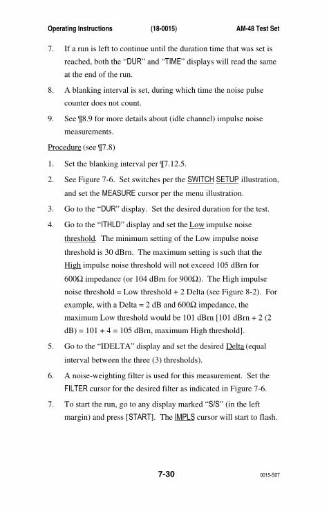
Operating Instructions (18-0015) AM-48 Test Set
0015-S077-30
7. If a run is left to continue until the duration time that was set is
reached, both the “DUR” and “TIME” displays will read the same
at the end of the run.
8. A blanking interval is set, during which time the noise pulse
counter does not count.
9. See ¶8.9 for more details about (idle channel) impulse noise
measurements.
Procedure (see ¶7.8)
1. Set the blanking interval per ¶7.12.5.
2. See Figure 7-6. Set switches per the SWITCH SETUP illustration,
and set the MEASURE cursor per the menu illustration.
3. Go to the “DUR” display. Set the desired duration for the test.
4. Go to the “ITHLD” display and set the Low impulse noise
threshold . The minimum setting of the Low impulse noise
threshold is 30 dBrn. The maximum setting is such that the
High impulse noise threshold will not exceed 105 dBrn for
600Ω impedance (or 104 dBrn for 900Ω). The High impulse
noise threshold = Low threshold + 2 Delta (see Figure 8-2). For
example, with a Delta = 2 dB and 600Ω impedance, the
maximum Low threshold would be 101 dBrn [101 dBrn + 2 (2
dB) = 101 + 4 = 105 dBrn, maximum High threshold].
5. Go to the “IDELTA” display and set the desired Delta (equal
interval between the three (3) thresholds).
6. A noise-weighting filter is used for this measurement. Set the
FILTER cursor for the desired filter as indicated in Figure 7-6.
7. To start the run, go to any display marked “S/S” (in the left
margin) and press [START]. The IMPLS cursor will start to flash.

AM-48 Test Set (18-0015) Operating Instructions
0015-S07 7-31
8. At any time, go to the “NOISE” display and read the real time
noise (always a whole number).
9. To stop the run before the duration time has elapsed, press
[STOP]. The IMPLS cursor will stop flashing.
10. When a run is stopped before the duration (“DUR”) time is up,
read the “TIME” display for the actual time of the run.
11. After the run, go to the respective display to read the low,
middle, and high threshold noise counts.
12. After the run, the parameter settings and the readings are stored
in non-volatile memory.
Operating Instructions (18-0015) AM-48 Test Set
0015-S077-32
AmeritecPERSONAL TRANSMISSION TEST SET
MODEL AM-48
SEND MEASURE FILTER
ON
ABSREL
SEND
ON/OFF
∇
∇
∇
DAMP
∇
∇
OFF
SEL
900Ω600Ω
∇
∇
∇
SEL
∇
∇
SEL
∇
∇
3K C-MSG
15K PROG
QUIET 1004 VAR
PAR
L/F
PAR3 TONE SWEEP
NOISE NOISE S/NHOLDTONE
IMPLS ØJTR JTR TRANS∇∆
•
•
MON RCVMON SNDTALK
∇
TERM∇
BRDG
∇∇•
4W•
TONEPULSEON HK
∇
∇•
MFDTMFSHIFT
ETR/NEXT
ETR/PREV
CANCEL
STOPSTART
4W/2WSND
4WRCV
+/-
∇
∇
∇
∇
∇
2W
4W REV
MIC
VOL
PRT EARDC9V
∇
∇
∇
•
SF SKPNOR
X TONE
∇
RCL/STO
∇
∇
•
∇
21 A3
54 B6
87 C9
0* D#
Set IMPLS
Select Filter
<ABS> or <REL>*
*For display switch in <REL>, level units are dB REL.
SWITCH SETUP
<SHIFT>
DB
DBRN
HZ
3K C-MSG
15K PROG
QUIET 1004 VAR
PAR
L/F
PAR3 TONE SWEEP
NOISE NOISE S/NHOLDTONE
IMPLS ØJTR JTR TRANS∇∆
Selected filter darkened
From any display marked S/S,press [START]/[STOP] tostart/stop impulse noise counter.
IMPLS darkened
•
IMPULSE NOISE DISPLAYS NAME RANGE NOTES
IMPULSETHRESHOLD
"ITHLD"
2, 3, 4, or 6 dB
Set Low Threshold for impulse noise.
Set difference between impulsenoise thresholds (low-to-midand mid-to-high).
Number of noise impulsesexceeding the low threshold.
Number of noise impulsesexceeding the middle threshold.
Number of noise impulsesexceeding the high threshold.
Select desired noise-weighting
The high threshold is set too high. Re-set "ITHLD" and/or"IDELTA".
filter: C-MSG, 3K, 15K, or PROG.A holding tone is not required.
0 to 9999
0 to 9999
0 to 9999
IMPULSE DELTA"IDELTA"
IMPULSE COUNTMIDDLE
"IMID"
IMPULSE COUNTHIGH
"IHI"
LOWIMPULSE COUNT
"ILO"
"NOISE"
POSSIBLE DISPLAY WHEN PRESS [START]
THRESHOLD TOO HIGH, "THLD 2 HI"
See ¶7.8 for general procedure to set new parameter values.
BLANKING INTERVAL value is set from the QUIET SEND display. See Figure 7-1.
HZ
HZ
•
•
.1 to 1999.9 minutes
.1 to 1999.9 minutes
30 to 101 dBrn(-60 to 20 dBm)
10 to 99 dBrn(-60 to 9 dBm)
0 No time-out
Set duration for timed studies.
Elapsed time of last timed study.
STUDY DURATION"DUR"
"TIME"
Figure 7-6. IMPLS MEASURE Displays
7.30 Measure Notched Noise1. See ¶8.5 for explanation of Notched Noise.
2. See Figure 7-7. Set switches per the SWITCH SETUP illustration,
and set the MEASURE cursor per the top menu illustration
(NOTCHED NOISE DISPLAY).
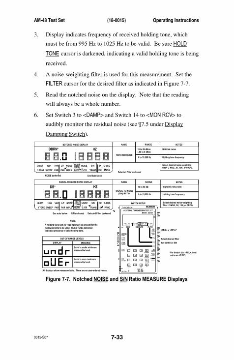
AM-48 Test Set (18-0015) Operating Instructions
0015-S07 7-33
3. Display indicates frequency of received holding tone, which
must be from 995 Hz to 1025 Hz to be valid. Be sure HOLD
TONE cursor is darkened, indicating a valid holding tone is being
received.
4. A noise-weighting filter is used for this measurement. Set the
FILTER cursor for the desired filter as indicated in Figure 7-7.
5. Read the notched noise on the display. Note that the reading
will always be a whole number.
6. Set Switch 3 to <DAMP> and Switch 14 to <MON RCV> to
audibly monitor the residual noise (see ¶7.5 under Display
Damping Switch ).
AmeritecPERSONAL TRANSMISSION TEST SET
MODEL AM-48
SEND MEASURE FILTER
ON
ABSREL
SEND
ON/OFF
∇
∇
∇
DAMP
∇
∇
OFF
SEL
900Ω600Ω
∇
∇
∇
SEL
∇
∇
SEL
∇
∇
3K C-MSG
15K PROG
QUIET 1004 VAR
PAR
L/F
PAR3 TONE SWEEP
NOISE NOISE S/NHOLDTONE
IMPLS ØJTR JTR TRANS∇∆
•
•
MON RCVMON SNDTALK
∇
TERM∇
BRDG
∇∇•
4W•
TONEPULSEON HK
∇
∇•
MFDTMFSHIFT
ETR/NEXT
ETR/PREV
CANCEL
STOPSTART
4W/2WSND
4WRCV
+/-
∇
∇
∇
∇
∇
2W
4W REV
MIC
VOL
PRT EARDC9V
∇
∇
∇
•
SF SKPNOR
X TONE
∇
RCL/STO
∇
∇
•
∇
21 A3
54 B6
87 C9
0* D#
Set NOISE or S/N
<ABS> or <REL>*
*For Switch 2 in <REL>, levelunits are dB REL
Select desired filter
SWITCH SETUP3K C-MSG
15K PROG
QUIET 1004 VAR
PAR
L/F
PAR3 TONE SWEEP
NOISE NOISE S/NHOLDTONE
IMPLS ØJTR JTR TRANS∇∆
S/N darkened
SIGNAL-TO-NOISE RATIO DISPLAY NAME RANGE NOTES
SIGNAL-TO-NOISE(S/N) RATIO
Signal-to-noise ratio
OUT-OF-RANGE LEVELS
DISPLAY MEANING
Level is under minimummeasurable level.
Level is over maximum
All displays show merasured data. There are no user-entered values.
measurable level.
HZ
•
DB* HZ
3K C-MSG
15K PROG
QUIET 1004 VAR
PAR
L/F
PAR3 TONE SWEEP
NOISE NOISE S/NHOLDTONE
IMPLS ØJTR JTR TRANS∇∆
NOISE darkened See Note below
Selected Filter darkened
Selected Filter darkened
A holding tone (995 to 1025 Hz) must be present for themeasurements to be valid. HOLD TONE darkenedindicates presence of valid holding tone.
DBRN*
•
NOTCHED NOISE DISPLAY NAME RANGE NOTES
NOTCHED NOISE
Notched noise
Holding tone frequency
Holding tone frequency
Select desired noise-weightingfilter: C-MSG, 3K, 15K, or PROG.
Select desired noise-weightingfilter: C-MSG, 3K, 15K, or PROG.
10 to 99 dBrrn
0 to 19,999 Hz
0 to 19,999 Hz
(-80 to 9 dBm)
10 to 50 dB
See note below
NOTE
Figure 7-7. Notched NOISE and S/N Ratio MEASURE Displays

Operating Instructions (18-0015) AM-48 Test Set
0015-S077-34
7.31 Measure S/N Ratio1. See ¶8.6 for explanation of S/N Ratio measurement.
2. See Figure 7-7. Set switches per the SWITCH SETUP illustration,
and set the MEASURE cursor per the bottom menu illustration
(SIGNAL-TO-NOISE RATIO DISPLAY).
3. Display indicates frequency of received holding tone, which
must be from 995 Hz to 1025 Hz to be valid. Be sure HOLD
TONE cursor is darkened, indicating a valid holding tone is being
received.
4. A noise-weighting filter is used for this measurement. Set the
FILTER cursor for the desired filter as indicated in Figure 7-7.
5. Read the signal-to-noise ratio on the display. Note that the
reading will always be a whole number.
6. Set Switch 3 to <DAMP> and Switch 14 to <MON RCV> to
audibly monitor the residual noise (see ¶7.5 under Display
Damping Switch ).
7.32 Measure Phase Jitter1. See ¶8.10 for explanation of Phase Jitter measurement.
2. See Figure 7-8. Set switches per the SWITCH SETUP illustration,
and set the MEASURE cursor per the top menu illustration
(PHASE JITTER DISPLAYS).
3. Go to “PLL” display. This indicates the phase-locked loop
generator frequency, which must be from 990 Hz to 1030 Hz for
a valid measurement. Be sure HOLD TONE cursor is darkened,
indicating a valid holding tone is being received.
4. Go to “RANGE” display. Press [4] or [2] for desired bandwidth
(4 Hz to 300 Hz or 20 Hz to 300 Hz).
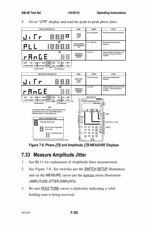
AM-48 Test Set (18-0015) Operating Instructions
0015-S07 7-35
5. Go to “JITR” display and read the peak-to-peak phase jitter.
AmeritecPERSONAL TRANSMISSION TEST SET
MODEL AM-48
SEND MEASURE FILTER
ON
ABSREL
SEND
ON/OFF
∇
∇
∇
DAMP
∇
∇
OFF
SEL
900Ω600Ω
∇
∇
∇
SEL
∇
∇
SEL
∇
∇
3K C-MSG
15K PROG
QUIET 1004 VAR
PAR
L/F
PAR3 TONE SWEEP
NOISE NOISE S/NHOLDTONE
IMPLS ØJTR JTR TRANS∇∆
•
•
MON RCVMON SNDTALK
∇
TERM∇
BRDG
∇∇•
4W•
TONEPULSEON HK
∇
∇•
MFDTMFSHIFT
ETR/NEXT
ETR/PREV
CANCEL
STOPSTART
4W/2WSND
4WRCV
+/-
∇
∇
∇
∇
∇
2W
4W REV
MIC
VOL
PRT EARDC9V
∇
∇
∇
•
SF SKPNOR
X TONE
∇
RCL/STO
∇
∇
•
∇
21 A3
54 B6
87 C9
0* D#
Set Ø JTR or
<ABS>
SWITCH SETUP
<SHIFT>
HZ
HZ
3K C-MSG
15K PROG
QUIET 1004 VAR
PAR
L/F
PAR3 TONE SWEEP
NOISE NOISE S/NHOLDTONE
IMPLS ØJTR JTR TRANS∇∆
See Note below Ø JTR darkened
•
•
PHASE JITTER DISPLAYS NAME RANGE NOTES
PHASEJITTER"JITR°"
AMPLITUDEJITTER"JITR°"
PHASE LOCKEDLOOP FREQUENCY
"PLL"
FREQUENCYBANDWIDTH
"RANGE"
FREQUENCYBANDWIDTH
"RANGE"
0.0 to 25.0 degrees
0.0 to 25.0 percent
0.0 to 1999.9 Hz
Peak-to-peak phase jitter displayed.
Peak-to-peak amplitude jitterdisplayed.
Phase-locked-loop frequencydisplayed.
to 300 Hz. Press [2] for 20 Hz toto 300 Hz.
Select bandwidth: Press [4] for 4 Hz4 or 20 Hz
to 300 Hz. Press [2] for 20 Hz toto 300 Hz.
Select bandwidth: Press [4] for 4 Hz4 or 20 Hz
DISPLAY CHARACTER CODE
Parameter Name (Fixed)
Key from which Programmed
See ¶7.8 for general procedure to set new parameter values.
User-Entered Value
Tone is Sent
HZ
3K C-MSG
15K PROG
QUIET 1004 VAR
PAR
L/F
PAR3 TONE SWEEP
NOISE NOISE S/NHOLDTONE
IMPLS ØJTR JTR TRANS∇∆
∇∆
∇∆
•
•
AMPLITUDE JITTER DISPLAYS NAME RANGE NOTES
See Note below JTR darkened
A holding tone (990 to 1030 Hz) must be present for themeasurements to be valid. HOLD TONE darkenedindicates presence of valid holding tone.
NOTE
JTR
Figure 7-8. Phase JTR and Amplitude JTR MEASURE Displays
7.33 Measure Amplitude Jitter1. See ¶8.11 for explanation of Amplitude Jitter measurement.
2. See Figure 7-8. Set switches per the SWITCH SETUP illustration,
and set the MEASURE cursor per the bottom menu illustration
(AMPLITUDE JITTER DISPLAYS).
3. Be sure HOLD TONE cursor is darkened, indicating a valid
holding tone is being received.
Operating Instructions (18-0015) AM-48 Test Set
0015-S077-36
4. Go to “RANGE” display. Press [4] or [2] for desired bandwidth
(4 Hz to 300 Hz or 20 Hz to 300 Hz).
5. Go to “JITR” display and read the peak-to-peak amplitude jitter.
7.34 Measure TransientsThese are timed tests, any or all of which can be performed at the
same time. See ¶7.24 for general information.
There are a total of 14 displays in the TRANS MEASURE mode, shown
in the two (2) pages of Figure 7-9.
See Figure 7-9 for all parameter settings and operations described in
this paragraph. Set switches per the SWITCH SETUP illustration, and
set the MEASURE and FILTER cursors per the menu illustration.
1. Measure Notched Impulse Noise . This measurement is identical
to the (idle channel) Impulse Noise measurement except that a
holding tone is required. The operating instructions are thus
identical, as indicated below.
a) Be sure HOLD TONE cursor is darkened, indicating a
valid holding tone.
b) See Figure 7-9. Note that the first eight (8) displays in
Figure 7-9 are identical to the eight (8) displays in
Figure 7-6.
c) Follow the procedure in ¶7.29, except that the TRANS
cursor will be darkened and flash during the run
instead of the IMPLS cursor. Note that the “NOISE”
display reads notched noise instead of idle channel
noise.

AM-48 Test Set (18-0015) Operating Instructions
0015-S07 7-37
2. Measure Phase Hits . See ¶8.13 for explanation of phase hit
measurement.
a) See Figure 7-9. Be sure HOLD TONE cursor is
darkened.
b) Go to “DUR” display and set the desired duration for
the test.
c) Go to “PTHLD” display and set the phase hit threshold.
d) Go to any display labeled “S/S” and press [START]; the
TRANS cursor will start to flash.
e) To stop the run before the duration time has elapsed,
press [STOP]. The TRANS cursor will stop flashing.
f) When the run is stopped before the duration (“DUR”)
time is up, read the “TIME” display for the actual time
of the run.
g) After the run, go to “PHIT” display to read the number
of phase hits.
h) After the run, the parameter settings and the readings
are stored in non-volatile memory.
3. Measure Gain Hits . See ¶8.14 for explanation of gain hit
measurement.
a) See Figure 7-9. Be sure HOLD TONE cursor is
darkened.
b) Go to “DUR” display and set the desired duration for
the test.
c) Go to “GTHLD” display and set the gain hit threshold.
d) Go to any display labeled “S/S” and press [START]; the
TRANS cursor will start to flash.
Operating Instructions (18-0015) AM-48 Test Set
0015-S077-38
e) To stop the run before the duration time has elapsed,
press [STOP]. The TRANS cursor will stop flashing.
f) When the run is stopped before the duration (“DUR”)
time is up, read the “TIME” display for the actual time
of the run.
g) After the run, go to “GHIT” display to read the number
of gain hits.
h) After the run, the parameter settings and the readings
are stored in non-volatile memory.
4. Measure Dropouts . See ¶8.15 for explanation of dropouts
measurement.
a) See Figure 7-9. Be sure HOLD TONE cursor is
darkened.
b) Go to “DUR” display and set the desired duration for
the test.
c) Go to any display labeled “S/S” and press [START]; the
TRANS cursor will start to flash.
d) To stop the run before the duration time has elapsed,
press [STOP]. The TRANS cursor will stop flashing.
e) When the run is stopped before the duration (“DUR”)
time is up, read the “TIME” display for the actual time
of the run.
f) After the run, go to “DROP” display to read the
number of dropouts (loss of holding tone).
g) After the run, the parameter settings and the readings
are stored in non-volatile memory.

AM-48 Test Set (18-0015) Operating Instructions
0015-S07 7-39
AmeritecPERSONAL TRANSMISSION TEST SET
MODEL AM-48
SEND MEASURE FILTER
ON
ABSREL
SEND
ON/OFF
∇
∇
∇
DAMP
∇
∇
OFF
SEL
900Ω600Ω
∇
∇
∇
SEL
∇
∇
SEL
∇
∇
3K C-MSG
15K PROG
QUIET 1004 VAR
PAR
L/F
PAR3 TONE SWEEP
NOISE NOISE S/NHOLDTONE
IMPLS ØJTR JTR TRANS∇∆
•
•
MON RCVMON SNDTALK
∇
TERM∇
BRDG
∇∇•
4W•
TONEPULSEON HK
∇
∇•
MFDTMFSHIFT
ETR/NEXT
ETR/PREV
CANCEL
STOPSTART
4W/2WSND
4WRCV
+/-
∇
∇
∇
∇
∇
2W
4W REV
MIC
VOL
PRT EARDC9V
∇
∇
∇
•
SF SKPNOR
X TONE
∇
RCL/STO
∇
∇
•
∇
21 A3
54 B6
87 C9
0* D#
Set TRANS
Select Filter
<ABS> or <REL>*
*For display switch in <REL>, level units are dB REL.
SWITCH SETUP
<SHIFT>
DB
DBRN
HZ
3K C-MSG
15K PROG
QUIET 1004 VAR
PAR
L/F
PAR3 TONE SWEEP
NOISE NOISE S/NHOLDTONE
IMPLS ØJTR JTR TRANS∇∆
Selected filter darkened
From any display marked S/S,press [START]/[STOP] tostart/stop transient counters.
TRANS darkened(flashes during run)
HOLD TONE darkened(valid holding tone)
TRANSIENT DISPLAYS (first 7 of 14) NAME RANGE NOTES
IMPULSETHRESHOLD
"ITHLD"
2, 3, 4, or 6 dB
Set Low Threshold for impulse noise.
Set difference between impulsenoise thresholds (low-to-midand mid-to-high).
Number of noise impulsesexceeding the low threshold.
Number of noise impulsesexceeding the middle threshold.
Number of noise impulsesexceeding the high threshold.
The high threshold is set too high. Re-set "ITHLD" and/or"IDELTA".
0 to 9999
0 to 9999
0 to 9999
IMPULSE DELTA"IDELTA"
IMPULSE COUNTMIDDLE
"IMID"
IMPULSE COUNTHIGH
"IHI"
LOWIMPULSE COUNT
"ILO"
POSSIBLE DISPLAY WHEN PRESS [START]
THRESHOLD TOO HIGH, "THLD 2 HI"
See ¶7.8 for general procedure to set new parameter values.Holding tone (995 to 1025 Hz) required.
BLANKING INTERVAL value is set from the QUIET SEND display. See Figure 7-1.
HZ
HZ
•
•
.1 to 1999.9 minutes
.1 to 1999.9 minutes
30 to 101 dBrn(-60 to 20 dBm)
0 No time-out
Set duration for timed studies.
Elapsed time of last timed study.
STUDY DURATION"DUR"
"TIME"S/S
S/S
S/S
S/S
Figure 7-9. TRANS MEASURE Displays, Page 1 of 2
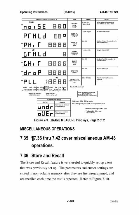
Operating Instructions (18-0015) AM-48 Test Set
0015-S077-40
DB
DBRN
3K C-MSG
15K PROG
QUIET 1004 VAR
PAR
L/F
PAR3 TONE SWEEP
NOISE NOISE S/NHOLDTONE
IMPLS ØJTR JTR TRANS∇∆
Selected filter darkened
From any display marked S/S,press [START]/[STOP] tostart/stop impulse noise counter.
•
•
TRANSIENT DISPLAYS (second 7 of 14) NAME RANGE NOTES
THRESHOLD
NOTCHEDNOISE
"PTHLD"
2, 3, 4, or 6 dB
Number of phase hits exceeding thephase hit threshold.
Number of gain hits exceeding thegain hit threshold.
Number of dropouts.
Select desired noise-weightingfilter: C-MSG, 3K, 15K, or PROG.
0 to 9999
0 to 9999
DROPOUTS"DROP"
"NOISE"
See ¶7.8 for general procedure to set new parameter values.
Holding tone (995 to 1025 Hz) required
Switch Setup is on page 1 of this Figure.
HZ
5 to 45 degrees
0 to 9999
10 to 99 dBrn(-80 to 9 dBm)
Set phase hit threshold.
Set gain hit threshold.
PHASE HIT
THRESHOLD"GTHLD"
GAIN HIT
COUNT"PHIT"
PHASE HIT
COUNT"GHIT"
GAIN HIT
S/S
S/S
S/S
S/S
S/SPHASE LOCKED
LOOP FREQUENCY"PLL"
0.0 to 1999.9 Hz Phase-locked-loop frequencydisplayed.
TRANS darkened(flashes during run)
HOLD TONE darkened(valid holding tone)
OUT-OF-RANGE LEVELS
DISPLAY MEANING
Level is under minimummeasurable level.
Level is over maximummeasurable level.
*For Switch 2 in <REL>, levelunits are dB REL
Figure 7-9. TRANS MEASURE Displays, Page 2 of 2
MISCELLANEOUS OPERATIONS
7.35 ¶7.36 thru 7.42 cover miscellaneous AM-48
operations.
7.36 Store and RecallThe Store and Recall feature is very useful to quickly set up a test
that was previously set up. The parameters and cursor settings are
stored in non-volatile memory after they are first programmed, and
are recalled each time the test is repeated. Refer to Figure 7-10.
AM-48 Test Set (18-0015) Operating Instructions
0015-S07 7-41
Recall . To recall a test setup previously stored:
1. Momentarily press Switch 9 to <RCL/STO>.
2. The prompt “RECALL?” will appear on the display.
3. Press a number key [0] thru [9] to recall a setup previously
stored on that key, or press [CANCEL] to abort.
Store . To store:
1. Adjust the AM-48 to the test setup and parameter settings to be
stored.
2. Press and hold Switch 9 to <RCL/STO> for about five (5)
seconds. <STO> is underlined to indicate that the store function
is enabled when Switch 9 is held down .
3. The “RECALL?” prompt will then change to “STORE?”.
4. Press a number key [0] thru [9] to store the setup on that key, or
press [CANCEL] to abort.

Operating Instructions (18-0015) AM-48 Test Set
0015-S077-42
AmeritecPERSONAL TRANSMISSION TEST SET
MODEL AM-48
SEND MEASURE FILTER
ON
ABSREL
SEND
ON/OFF
∇
∇
∇
DAMP
∇
∇
OFF
SEL
900Ω600Ω
∇
∇
∇
SEL
∇
∇SEL
∇
∇
3K C-MSG
15K PROG
QUIET 1004 VAR
PAR
L/F
PAR3 TONE SWEEP
NOISE NOISE S/NHOLDTONE
IMPLS ØJTR JTR TRANS∇∆
•
•
MON RCVMON SNDTALK
∇
TERM∇
BRDG
∇∇•
4W•
TONEPULSEON HK
∇
∇•
MFDTMFSHIFT
ETR/NEXT
ETR/PREV
CANCEL
STOPSTART
4W/2WSND
4WRCV
+/-
∇
∇
∇
∇
∇
2W
4W REV
MIC
VOL
PRT EARDC9V
∇
∇
∇
•
SF SKPNOR
X TONE∇
RCL/STO
∇
∇
•
∇
21 A3
54 B6
87 C9
0* D#
<SHIFT>
<RCL/STO>
SWITCH SETUP
STORE AND RECALL
QUESTION MARKS
WITH NUMBER KEYS[0] THRU [9]
•
•
Figure 7-10. Recall and Store Operations
Parameters and cursor settings that are saved/stored by the
STORE/RECALL function are listed below:
Send Mode Measure Mode
Noise-Weighting Filter Selected Send Level
Send Variable Frequency Sweep Start Frequency
Sweep Stop Frequency Sweep Step Frequency
Sweep Rate Duration Time
Elapsed Time Impulse Threshold
Impulse Delta Threshold Phase Hit Threshold
Gain Hit Threshold
Jitter Range (4 Hz or 20 Hz High Pass)
AM-48 Test Set (18-0015) Operating Instructions
0015-S07 7-43
7.37 Dialing1. For DTMF or MF dialing, set desired send level per ¶7.12.3.
2. Set Switch 10 to <2W>, <4W>, or <4W REV> for desired 2-wire
or 4-wire line connection.
3. Match line impedance per ¶6.4 or 6.5. For Dial Pulse (DP), set
Switch 13 to <BRDG> while dialing, and set to <TERM> when
making measurements.
4. Set Switches 7 and 12 for dialing mode per Table 7-6.
5. The line connected to the AM-48 should provide dial tone.
Adjust speaker volume to a comfortable level.
6. Table 7-7 lists the MF and DTMF dual tones on each of the
keys. Note that there is no MF on key [D].
7. Dial number using keypad. See Figure 5-6 for dial display when
Switch 2 is in <SEND>. If timeout occurs, go back on hook by
setting Switch 12 to <ON HK> for two to three seconds, then
switch back to <PULSE> or <TONE> to go back off-hook.
Re-enter dialed number.
8. If a person has been dialed, press Switch 14 to <TALK> and
speak into the microphone. To listen to the other person, release
<TALK> to <MON SND>.
9. If an Ameritec AM3-2A DTMF Commandable Responder has
been called, it will automatically answer ringing and be open to
DTMF commands. See Table 7-6 for DTMF dialing setup and
dial appropriate DTMF commands.
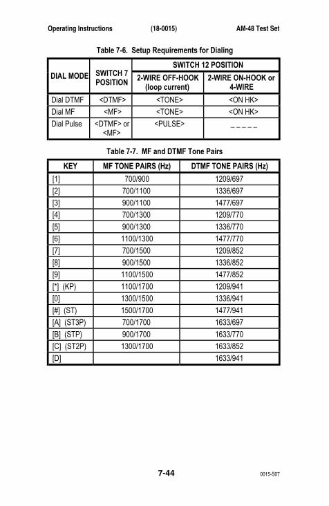
Operating Instructions (18-0015) AM-48 Test Set
0015-S077-44
Table 7-6. Setup Requirements for Dialing
SWITCH 12 POSITION DIAL MODE SWITCH 7
POSITION 2-WIRE OFF-HOOK(loop current)
2-WIRE ON-HOOK or4-WIRE
Dial DTMF <DTMF> <TONE> <ON HK>
Dial MF <MF> <TONE> <ON HK>
Dial Pulse <DTMF> or<MF>
<PULSE> _ _ _ _ _
Table 7-7. MF and DTMF Tone Pairs
KEY MF TONE PAIRS (Hz) DTMF TONE PAIRS (Hz)
[1] 700/900 1209/697
[2] 700/1100 1336/697
[3] 900/1100 1477/697
[4] 700/1300 1209/770
[5] 900/1300 1336/770
[6] 1100/1300 1477/770
[7] 700/1500 1209/852
[8] 900/1500 1336/852
[9] 1100/1500 1477/852
[*] (KP) 1100/1700 1209/941
[0] 1300/1500 1336/941
[#] (ST) 1500/1700 1477/941
[A] (ST3P) 700/1700 1633/697
[B] (STP) 900/1700 1633/770
[C] (ST2P) 1300/1700 1633/852
[D] 1633/941
AM-48 Test Set (18-0015) Operating Instructions
0015-S07 7-45
7.38 TalkingThe AM-48 can be used as a telephone “butt-set” (also see ¶3.5.14).
1. To talk , hold down Switch 14 in <TALK> position and speak into
the microphone (labeled MIC). See Figure 3-1 for microphone
location.
2. “VOICE” appears on the display when <TALK> is pressed and
Switch 2 is in <SEND>.
3. To listen , release <TALK> switch to <MON SND>. SEND cursor
will default to QUIET mode.
4. For more privacy or better listening clarity, use the earphone
supplied with the AM-48.
5. See Figure 3-2 for the location of the earphone jack, <EAR>, on
the bottom of the AM-48.
7.39 PrintingThis paragraph is divided into two (2) main parts:
A. Operation instructions for the AM-47 Hand-Held Printer
B. Explanation of the information given in AM-48 Printouts
A. AM-47 HAND-HELD PRINTER: OPERATION
See ¶3.9 and Figure 3-8 and 3-9 for a physical and functional
description of the AM-47 Hand-Held Printer.
Paper Roll Installation . Refer to Figure 3-9.
1. For additional rolls of paper, order Part No. 26-0014.
2. Push up on the end of the housing (as indicated by arrow) to
remove Paper Roll Compartment cover.

Operating Instructions (18-0015) AM-48 Test Set
0015-S077-46
3. As illustrated in Figure 3-9:
a) Install Paper Roll.
b) Feed paper into slot.
c) Push [PAPER ADVANCE] button to route paper through.
4. Re-install compartment cover.
Self Test . For a printout of all possible characters:
1. Simultaneously hold down the [PAPER ADVANCE] button and set
the Power Switch ON.
2. Self-Test printouts will be output for as long as the [PAPER
ADVANCE] button is held down continuously (from the time
power is first turned ON).
Charging Considerations . The AM-47 NiCad battery pack is charged
through the AC Adapter (70-0029); see Figure 6-3 for connection.
Note the following concerning the charging process:
1. Charging is controlled by a microprocessor that is programmed
to run the charging circuitry without sensing the actual charged
or discharged state of the battery pack.
2. With the AC Adapter connected, each time the power is turned
ON , the microprocessor assumes the worst case and goes into a
full 14-hour charge cycle.
3. With the AC Adapter connected and the power OFF , the AM-47
is charged with a very low trickle current which takes several
days to charge the battery pack.
AM-48 Test Set (18-0015) Operating Instructions
0015-S07 7-47
Note: The AC Adapter is only for charging the batteries. If
batteries are dead, the AC Adapter will not power the unit.
Carefully observe that the AM-47 is normally charged with
the Power ON, even though many other devices are
typically charged with the power OFF.
4. The AC Adapter can be left continuously connected to the
AM-47. There is no danger of “overcharging” the battery pack.
5. There are two (2) charging procedures:
a) A normal procedure.
b) A procedure if the battery pack is completely
discharged .
6. After the charging cycle, the POWER LED will blink. A timer is
also set which will start the charge cycle again after it has
decremented to zero. Each time a line is printed, the timer is
decremented a certain amount. If the POWER Switch is left ON,
the AM-47 can print about 10,000 lines before the timer
decrements to zero and a new charge cycle is initiated.
Normal Charging Procedure
1. Connect the AC Adapter (70-0029) as shown in Figure 6-3.
2. Turn the POWER Switch ON.
3. The POWER LED will light, indicating charging. (If the LED
does not light, the Battery Pack is completely discharged. Go to
the next procedure.
4. When the charging cycle is complete (after about 14 hours), the
POWER LED will blink.
Operating Instructions (18-0015) AM-48 Test Set
0015-S077-48
Note: Each time power is turned ON with the AC Adapter
connected, the AM-47 will go through a complete charging
cycle, regardless of the charge of the battery pack.
Charging Procedure When Battery Pack Completely Discharged
1. Connect the AC Adapter (70-0029) as shown in Figure 6-3.
2. Turn the POWER Switch ON to confirm Battery Pack is
completely discharged.
3. If Battery Pack is completely discharged, the POWER LED will
not light .
4. Turn the POWER Switch OFF. This will initiate a trickle charge
that will charge the Battery Pack enough to operate the
microprocessor-controlled charging circuitry.
5. Leave the POWER Switch OFF for about one (1) hour.
6. Turn the POWER Switch ON.
7. The POWER LED will now light continuously, indicating that the
full charge cycle has begun.
8. After about 14 hours, the POWER LED will start to blink,
indicating charging is complete.
Ribbon Cartridge Replacement. Refer to Figure 3-9.
1. For replacement Ribbon Cartridges, order Part No. 26-0015.
2. Push up on end of housing to remove Paper Roll Compartment
cover.
3. See Figure 3-9:
a) Observe how the ribbon is routed on the old cartridge.
b) Push on the end of the cartridge (as indicated) to eject
the old cartridge.
AM-48 Test Set (18-0015) Operating Instructions
0015-S07 7-49
c) Snap in the new cartridge, being careful to insert the
ribbon correctly.
d) Rotate the manual Ribbon Take-Up to apply tension to
the ribbon.
4. Re-install the Compartment Cover.
B. AM-48 PRINTOUTS
Connect the AM-47 Hand-Held Printer or other printer to the AM-48
per ¶6.3 and Figure 6-3. There are two (2) methods to obtain an
AM-48 printout:
1. Momentarily press Switch 9 to <PRINT> to get a printout on
demand .
2. During a timed study (Impulse Noise or Transient Tests), there
is an automatic printout every 15 minutes, as well as at the end
of the timed study.
Note: The content of a printout depends on what mode is being
displayed at the time of the printout.
Figures 7-11 thru 7-13 show the switch setups and sample printouts
for each SEND and MEASURE mode. Note:
1. For modes with more than one display, a printout can be made
from any display of the selected mode.
2. Printouts are shown exactly as they are output by the AM-47
Hand-Held Printer, in a 24-column format. When there is more
than one (1) row to a printout, the rows after the first are
indented by one (1) space.

Operating Instructions (18-0015) AM-48 Test Set
0015-S077-50
3. In the NOTES column, the title of the printout is underlined and
variable parameters are defined in the parentheses next to their
printout. Definitions for more than one parameter are separated
by a slash, “/”. Units of measurement are given only if not
shown in the printout.
4. Asterisks, “*” or “**”, are used to reference notes.
5. For any measurements requiring a holding tone (HT), “HT-ON”
indicates that the holding tone cursor was darkened at the time
of the printout, meaning the measurement is valid. “HT-OFF”
means an invalid measurement because the holding tone was not
to specification.
6. The CMSG filter is shown in each printout of a measurement
requiring a noise-weighting filter. 3K, 15K, or PROG (also PSHO
or SWTD for AM-48E) would appear in this same position of the
readout if one of these filters were selected.
7. Noise levels and thresholds are in “dBrn”, which applies to the
AM-48 only; units would be “dBm” for the AM-48E.
8. “OVER” or “UNDER” readings could appear for any level
measurement – only some samples are shown. These out-of-
range indications are based on the Absolute reading, even for
Relative printouts. “OVER” will print out for levels received
greater than +10.9 dBm, and “UNDER” will print out for levels
lower than –65.0 dBm. For Send and Measure ranges of values,
See Figure 7-1 thru 7-9 in the tables next to the displays.
9. An example of the meaning of Relative measurements is shown
in Figure 7-13. In the second entry, “+ 5.1rel-12.3” means
“+5.1 dB relative to –12.3 dBm” (the reading when Switch 2
was set from <ABS> to <REL>).

AM-48 Test Set (18-0015) Operating Instructions
0015-S07 7-51
10. In Figure 7-13, Relative noise printouts are possible for IMPLS
and TRANS cursor settings. These are the same as the Relative
noise measurements shown in Figure 7-13 printouts which start
with “HZ” and “NN”.
AmeritecPERSONAL TRANSMISSION TEST SET
MODEL AM-48
SEND MEASURE FILTER
ON
ABSREL
SEND
ON/OFF
∇
∇
∇
DAMP
∇
∇
OFF
SEL
900Ω600Ω
∇
∇
∇SEL
∇
∇
SEL
∇
∇
3K C-MSG
15K PROG
QUIET 1004 VAR
PAR
L/F
PAR3 TONE SWEEP
NOISE NOISE S/NHOLDTONE
IMPLS ØJTR JTR TRANS∇∆
•
•
MON RCVMON SNDTALK
∇
TERM∇
BRDG
∇∇•
4W•
TONEPULSEON HK
∇
∇•
MFDTMFSHIFT
ETR/NEXT
ETR/PREV
CANCEL
STOPSTART
4W/2WSND
4WRCV
+/-
∇
∇
∇
∇
∇
2W
4W REV
MIC
VOL
PRT EARDC9V
∇
∇
∇
•
SF SKPNOR
X TONE
∇
RCL/STO
∇
∇
•
∇
21 A3
54 B6
87 C9
0* D#
Set SEND mode: QUIET
<SEND>
1004VAR3TONE*
*SLOPE for AM-48E
SWEEPPAR
SWITCH SETUP
Press <PRINT>
SENDCURSOR
SAMPLE PRINTOUT NOTES (variable parametersdefined in parentheses)
QUIET SND QUIET Send Quiet Termination
1004 SND 1004 HT +00.0dBm Send 1004 Hz Tone (Level)HT = Holding Tone
VAR SND 15000Hz –10.0dBm Send Continuous Tone (Frequency/Level)
3TONE(SLOPE forAM-48E)
SND 3TONE* -15.odB Send 404, 1004, 2804, Hz(AM-48E: 404, 1004, 2004, 3004 Hz)Tones 5 Sec Duration(Level) *SLOPE for AM-48E
SWEEP SND SWEEP +00.0dBm 204Hz-19904Hz SFSKIP* 100 STEP 1.0 RATE
Send Programmed Sweep (Level)(Start frequency-Stop Frequency)*SFSKIP is printed only if Switch8 set to <SF SKIP>

Operating Instructions (18-0015) AM-48 Test Set
0015-S077-52
SENDCURSOR
SAMPLE PRINTOUT NOTES (variable parametersdefined in parentheses)
PAR SND PAR –20.5dBm Send Peak-to-Average Waveform (Level)
Figure 7-11. SEND Printouts
AmeritecPERSONAL TRANSMISSION TEST SET
MODEL AM-48
SEND MEASURE FILTER
ON
ABSREL
SEND
ON/OFF
∇
∇
∇
DAMP
∇
∇
OFF
SEL
900Ω600Ω
∇
∇
∇
SEL
∇
∇
SEL
∇
∇
3K C-MSG
15K PROG
QUIET 1004 VAR
PAR
L/F
PAR3 TONE SWEEP
NOISE NOISE S/NHOLDTONE
IMPLS ØJTR JTR TRANS∇∆
∇∆
•
•
MON RCVMON SNDTALK
∇
TERM∇
BRDG
∇∇•
4W•
TONEPULSEON HK
∇
∇•
MFDTMFSHIFT
ETR/NEXT
ETR/PREV
CANCEL
STOPSTART
4W/2WSND
4WRCV
+/-
∇
∇
∇
∇
∇
2W
4W REV
MIC
VOL
PRT EARDC9V
∇
∇
∇
•
SF SKPNOR
X TONE
∇
RCL/STO
∇
∇
•
∇
21 A3
54 B6
87 C9
0* D#
Set SEND mode: L/F
<ABS>
NOISE (HZ)NOISE (NN)S/NPARIMPLSøJTR
JTRTRANS
SWITCH SETUP
Press <PRINT>
MEASURECURSOR
SAMPLE PRINTOUT NOTES (variable parametersdefined in parentheses)
L/F LF OVER dBm 1004Hz Measure Level/FrequencyLevel is too high to measure
L/F LF UNDERdBm 1004Hz Measure Level/FrequencyLevel is too low to measure
L/F LF +10.2dBm 12345Hz Measure Level/Frequency(Level/Frequency)
NOISE NZ +15.0dBrn CMSG* Measure Idle Channel Noise (Level) *Filter selected

AM-48 Test Set (18-0015) Operating Instructions
0015-S07 7-53
MEASURECURSOR
SAMPLE PRINTOUT NOTES (variable parametersdefined in parentheses)
NOISE NN +12.0dBrn CMSG* 1020HT=ON**
Measure Notched Noise (Level) *Filter selected **Valid Measurement
NOISE NN +12.0dBrn CMSG* 980HT=OFF**
Measure Notched Noise (Level) *Filter selected **Invalid Measurement
S/N SN +50.0dB CMSG* 1000HT=ON**
Measure Signal-to-Noise Ratio (Difference between levels of holding tone and notched noise) *Filter selected **Valid Measurement
PAR PAR –15.7dBm 85par Measure Peak-to-Average Ratio(Level/Received PAR Reading)
IMPLS IMP 15.0DUR 11.4TIMTHLD 80dBrn DELTA 2dBBLANKING 125ms CMSG*7654LO 4321MID 1234HI
Measure Idle Channel Impulse Noise (Duration/Elapsed Time, minutes) (Low Threshold/Threshold Diff.) (Blanking Interval) (Low/Mid/Hi Impulse Noise Counts) *Filter Selected
ØJTR PHJTR+17.2 RANGE 4-300 1000HT=ON* 999.6 PLL
Measure Phase Jitter (P/P Phase Jitter,º/Bandwidth,Hz)(Phase-Locked-Loop Frequency,Hz) *Valid Measurement
∆ ∇ JTR AMJTR+14.8% RANGE 20-300 998HT=ON*
Measure Amplitude Jitter (P/P Amplitude Jitter/Bandwidth,Hz) *Valid Measurement
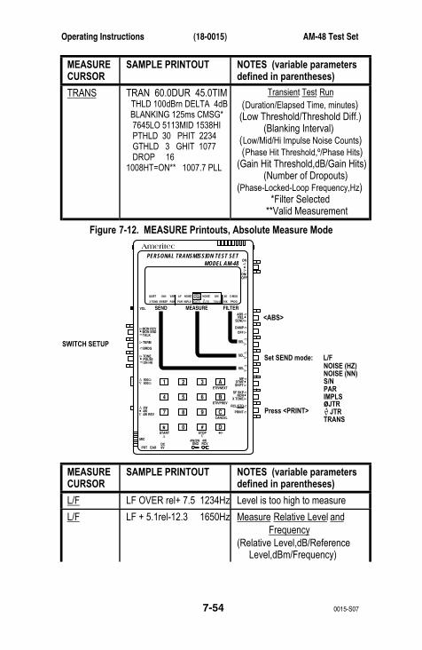
Operating Instructions (18-0015) AM-48 Test Set
0015-S077-54
MEASURECURSOR
SAMPLE PRINTOUT NOTES (variable parametersdefined in parentheses)
TRANS TRAN 60.0DUR 45.0TIM THLD 100dBrn DELTA 4dB BLANKING 125ms CMSG* 7645LO 5113MID 1538HI PTHLD 30 PHIT 2234 GTHLD 3 GHIT 1077 DROP 161008HT=ON** 1007.7 PLL
Transient Test Run (Duration/Elapsed Time, minutes) (Low Threshold/Threshold Diff.) (Blanking Interval) (Low/Mid/Hi Impulse Noise Counts) (Phase Hit Threshold,º/Phase Hits)(Gain Hit Threshold,dB/Gain Hits) (Number of Dropouts)(Phase-Locked-Loop Frequency,Hz) *Filter Selected **Valid Measurement
Figure 7-12. MEASURE Printouts, Absolute Measure Mode
AmeritecPERSONAL TRANSMISSION TEST SET
MODEL AM-48
SEND MEASURE FILTER
ON
ABSREL
SEND
ON/OFF
∇
∇
∇
DAMP
∇
∇
OFF
SEL
900Ω600Ω
∇
∇
∇
SEL
∇
∇
SEL
∇
∇
3K C-MSG
15K PROG
QUIET 1004 VAR
PAR
L/F
PAR3 TONE SWEEP
NOISE NOISE S/NHOLDTONE
IMPLS ØJTR JTR TRANS∇∆
∇∆
•
•
MON RCVMON SNDTALK
∇
TERM∇
BRDG
∇∇•
4W•
TONEPULSEON HK
∇
∇•
MFDTMFSHIFT
ETR/NEXT
ETR/PREV
CANCEL
STOPSTART
4W/2WSND
4WRCV
+/-
∇
∇
∇
∇
∇
2W
4W REV
MIC
VOL
PRT EARDC9V
∇
∇∇
•
SF SKPNOR
X TONE
∇
RCL/STO
∇
∇
•
∇
21 A3
54 B6
87 C9
0* D#
Set SEND mode: L/F
<ABS>
NOISE (HZ)NOISE (NN)S/NPARIMPLSøJTR
JTRTRANS
SWITCH SETUP
Press <PRINT>
MEASURECURSOR
SAMPLE PRINTOUT NOTES (variable parametersdefined in parentheses)
L/F LF OVER rel+ 7.5 1234Hz Level is too high to measure
L/F LF + 5.1rel-12.3 1650Hz Measure Relative Level and Frequency(Relative Level,dB/Reference Level,dBm/Frequency)
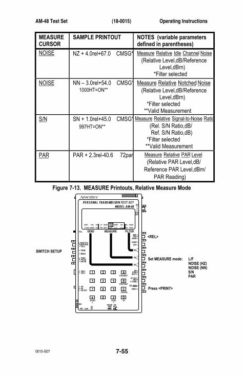
AM-48 Test Set (18-0015) Operating Instructions
0015-S07 7-55
MEASURECURSOR
SAMPLE PRINTOUT NOTES (variable parametersdefined in parentheses)
NOISE NZ + 4.0rel+67.0 CMSG* Measure Relative Idle Channel Noise (Relative Level,dB/Reference Level,dBrn) *Filter selected
NOISE NN – 3.0rel+54.0 CMSG* 1000HT=ON**
Measure Relative Notched Noise (Relative Level,dB/Reference Level,dBrn) *Filter selected **Valid Measurement
S/N SN + 1.0rel+45.0 CMSG* 997HT=ON**
Measure Relative Signal-to-Noise Ratio (Rel. S/N Ratio,dB/ Ref. S/N Ratio,dB) *Filter selected **Valid Measurement
PAR PAR + 2.3rel-40.6 72par Measure Relative PAR Level (Relative PAR Level,dB/ Reference PAR Level,dBm/ PAR Reading)
Figure 7-13. MEASURE Printouts, Relative Measure ModeAmeritec
PERSONAL TRANSMISSION TEST SETMODEL AM-48
SEND MEASURE FILTER
ON
ABSREL
SEND
ON/OFF
∇
∇
∇
DAMP
∇
∇
OFF
SEL
900Ω600Ω
∇
∇
∇
SEL
∇
∇
SEL
∇
∇
3K C-MSG
15K PROG
QUIET 1004 VAR
PAR
L/F
PAR3 TONE SWEEP
NOISE NOISE S/NHOLDTONE
IMPLS ØJTR JTR TRANS∇∆
•
•
MON RCVMON SNDTALK
∇
TERM∇
BRDG
∇∇•
4W•
TONEPULSEON HK
∇
∇•
MFDTMFSHIFT
ETR/NEXT
ETR/PREV
CANCEL
STOPSTART
4W/2WSND
4WRCV
+/-
∇
∇
∇
∇
∇
2W
4W REV
MIC
VOL
PRT EARDC9V
∇
∇
∇
•
SF SKPNOR
X TONE
∇
RCL/STO
∇
∇
•
∇
21 A3
54 B6
87 C9
0* D#
Set MEASURE mode: L/F
<REL>
NOISE (HZ)NOISE (NN)S/NPAR
SWITCH SETUP
Press <PRINT>
Operating Instructions (18-0015) AM-48 Test Set
0015-S077-56
7.40 Auto Study Result SaveAt the end of timed study (impulse or transient test), the AM-48
automatically stores the results and associated setup parameters in
non-volatile memory. Whenever the AM-48 is turned on, the results
of the last impulse or transient study are automatically recalled. The
following measurements and parameters are automatically stored and
recalled:
Impulse LO count Impulse MID countImpulse HI count Phase hit countGain hit count Dropout countElapsed time Impulse thresholdImpulse delta threshold Phase hit thresholdGain hit threshold
Note that parameter setting will not be stored if the [START] key is
not pressed to actually run the impulse or transient test. Only the
results of the last timed test that was run are stored.
Timed tests are not affected by the automatic power shutdown
feature. The AM-48 will not turn itself off while an impulse or
transient study is in progress. The power-off timer is reset to
maximum time when [START] is pressed and does not operate
during the study. As soon as the study is over, the power-off timer
starts running with maximum time.
7.41 Impedance Adapter Measurement CorrectionsThe Impedance Adapter is illustrated in Figure 3-10. Figure 9-2
illustrates the Impedance Adapter’s schematic diagram. See ¶6.5 for
connection instructions. When the line is connected to the AM-48
through the Impedance Adapter, the display reading needs to be
corrected.
AM-48 Test Set (18-0015) Operating Instructions
0015-S07 7-57
Table 7-8 lists the correction values to add to or subtract from the
value on the display. To calculate the correct level on the line, add
the correction value to a MEASURE level or noise display reading
(Switch 2 in <ABS> or <REL>); subtract the correction value from a
SEND level display reading (Switch 2 in <SEND>).
Table 7-8. Impedance Adapter Correction Values
IMPEDANCE ADAPTER SETTING CORRECTION VALUE
1200 OHM900 OHM
THRU (600 OHM)150 OHM135 OHM
75 OHM
3.0 dB1.8 dB
0 dB6.0 dB6.5 dB9.0 dB
Memory Aid . To remember whether to add or subtract the correction
value, it is helpful to think of the Impedance Adapter as introducing
loss. the signal out of the Impedance Adapter is thus less than the
signal into it. Refer to Figure 7-14.
For an AM-48 SEND mode, the signal actually sent on the line
(beyond the Impedance Adapter) is less than the signal sent from the
AM-48 (as indicated on the display). The correction factor is thus
subtracted from the display reading to give the actual level of the
signal sent on the line.
For an AM-48 MEASURE mode, the signal received by the AM-48 (as
indicated on the display) is less than the incoming level from the line.
The correction factor is thus added to the display reading to give the
actual level of the signal received at the line.
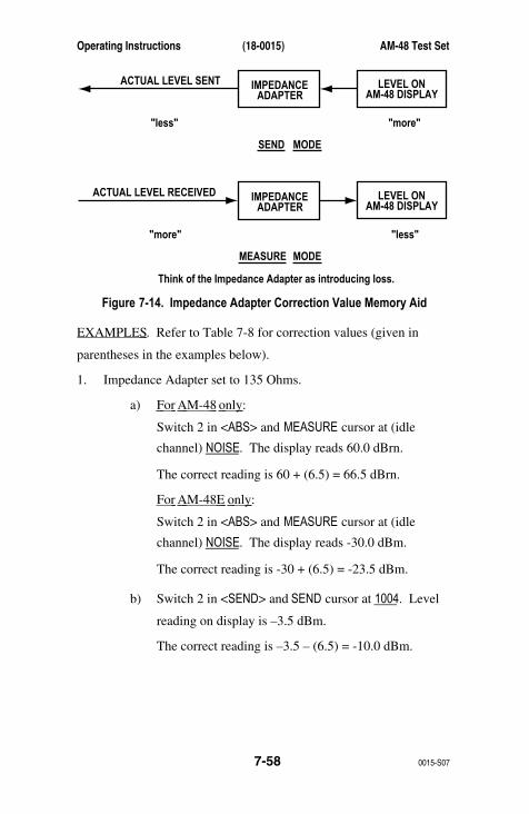
Operating Instructions (18-0015) AM-48 Test Set
0015-S077-58
IMPEDANCEACTUAL LEVEL SENTADAPTER
LEVEL ON
SEND MODE
AM-48 DISPLAY
"less" "more"
IMPEDANCEACTUAL LEVEL RECEIVEDADAPTER
LEVEL ON
MEASURE MODE
AM-48 DISPLAY
"less""more"
Think of the Impedance Adapter as introducing loss.
Figure 7-14. Impedance Adapter Correction Value Memory Aid
EXAMPLES . Refer to Table 7-8 for correction values (given in
parentheses in the examples below).
1. Impedance Adapter set to 135 Ohms.
a) For AM-48 only :
Switch 2 in <ABS> and MEASURE cursor at (idle
channel) NOISE. The display reads 60.0 dBrn.
The correct reading is 60 + (6.5) = 66.5 dBrn.
For AM-48E only :
Switch 2 in <ABS> and MEASURE cursor at (idle
channel) NOISE. The display reads -30.0 dBm.
The correct reading is -30 + (6.5) = -23.5 dBm.
b) Switch 2 in <SEND> and SEND cursor at 1004. Level
reading on display is –3.5 dBm.
The correct reading is –3.5 – (6.5) = -10.0 dBm.
AM-48 Test Set (18-0015) Operating Instructions
0015-S07 7-59
2. Impedance Adapter set to 1200 Ohms.
(a) Switch 2 in <ABS> and MEASURE cursor at L/F. Level
reading on display is -20.0 dBm.
The correct reading is –20.0 + (3.0) = -17.0 dBm.
(b) Switch 2 in <SEND> and SEND cursor at PAR. Level
reading on display is –3.0 dBm.
The correct reading is –3.0 – (3.0) = -6.0 dBm.
7.42 Auto CalibrateNote: Auto-calibrate is only performed during servicing of the
AM-48. The unit stays in calibration during normal
operation..
Instructions to execute the AM-48 automatic self-calibrate:
1. Go to the QUIET SEND display, “_ _ _ _ _ _ _ _”, by setting
switches as shown in Figure 7-15.
2. Press [C] and hold for about five (5) seconds.
3. The display responds with a series of prompts shown and
explained in Figure 7-15.
4. Answer each prompt with “yes” or “no”.
a) Press [ETR/NEXT] for “yes”.
b) Press [CANCEL] for “no”, which aborts the auto
calibrate sequence.
5. After the last prompt, the AM-48 will proceed with an auto
calibrate of the measurement circuits.

Operating Instructions (18-0015) AM-48 Test Set
0015-S077-60
AmeritecPERSONAL TRANSMISSION TEST SET
MODEL AM-48
SEND MEASURE FILTER
ON
ABSREL
SEND
ON/OFF
∇
∇
∇
DAMP
∇
∇
OFF
SEL
900Ω600Ω
∇
∇
∇
SEL
∇
∇
SEL
∇
∇3K C-MSG
15K PROG
QUIET 1004 VAR
PAR
L/F
PAR3 TONE SWEEP
NOISE NOISE S/NHOLDTONE
IMPLS ØJTR JTR TRANS∇∆
•
•
MON RCVMON SNDTALK
∇
TERM∇
BRDG
∇∇•
4W•
TONEPULSEON HK
∇
∇•
MFDTMFSHIFT
ETR/NEXT
ETR/PREV
CANCEL
STOPSTART
4W/2WSND
4WRCV
+/-
∇
∇
∇
∇
∇
2W
4W REV
MIC
VOL
PRT EARDC9V
∇
∇∇
•
SF SKPNOR
X TONE
∇
RCL/STO
∇
∇
•
∇
21 A3
54 B6
87 C9
0* D#
Set QUIET
<SEND>
SWITCH SETUP
<SHIFT>
3K C-MSG
15K PROG
QUIET 1004 VAR
PAR
L/F
PAR3 TONE SWEEP
NOISE NOISE S/NHOLDTONE
IMPLS ØJTR JTR TRANS∇∆
QUIET darkened
DISPLAYS NAME CONDITION TO CHECK BEFORE PROCEEDING
AUTO CAL?
Press [ETR/NEXT] to proceed with Auto Calibrate.Press [CANCEL] to abort.
Be sure holding circuit is on hook (Switch 12 in <ON HK>).
Be sure Switch 10 is in <4W. (or <4W REV>).
Be sure Switch 11 is in <900Ω>.
Be sure Switch 13 is in <TERM>.
Be sure a cable is installed to loop back the send pairto the receive pair (see Figure 5-1 for possible connection).
After each prompt, check that the indicated setupis made before pressing [ETR/NEXT] to proceed.Press [CANCEL] at any time to abort Auto Calibrate.
ON HOOK?
900 OHM?
4 WIRE?
LOOP?
TERM?
•
•
•
Figure 7-15. AM-48 Auto Calibrate Prompts
AM-48 Test Set (18-0015) Measurements
0015-S08 8-1
8. EXPLANATION AND APPLICATION OFMEASUREMENTS
8.1 IntroductionThis section gives the theory behind the measurements whose
operating instructions are described in Section 7. The meaning of the
measurements and how they are used is discussed. This section is
divided into the following paragraphs:
8.2 Units of Measurement
8.3 Level (Gain or Loss) and Frequency
8.4 Idle Channel Noise
8.5 Notched Noise (Noise with Tone)
8.6 Signal-to-Noise
8.7 PAR
8.8 Gain Slope
8.9 Idle Channel Impulse Noise
8.10 Phase Jitter
8.11 Amplitude Jitter
8.12 Notched Impulse Noise
8.13 Phase Hits
8.14 Gain Hits
8.15 Dropouts
8.2 Units of MeasurementAs with any system of measurement, standard units of measurement
have been established in transmission testing to enable you to
meaningfully evaluate measurements and make comparisons of the
results
This paragraph discusses units of measurement used in analog
transmission level and noise measurements. Refer to Figure 8-1.
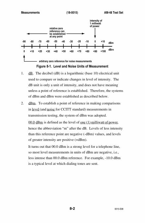
Measurements (18-0015) AM-48 Test Set
0015-S088-2
intensity of
arbitrary zero reference for noise measurements
1 milliwattof power
relative zeroreference canbe establishedat any point
-90 -80 -70 -60 -50 -40 -30 -20 -10 0 +10
0 +10 +20 +30 +40 +50 +60 +70 +80 +90 +100dBrn
dBm
Figure 8-1. Level and Noise Units of Measurement
1. dB . The decibel (dB) is a logarithmic (base 10) electrical unit
used to compare or indicate changes in level of intensity. The
dB unit is only a unit of intensity, and does not have meaning
unless a point of reference is established. Therefore, the systems
of dBm and dBrn were established as described below.
2. dBm . To establish a point of reference in making comparisons
in level (and noise for CCITT standard) measurements in
transmission testing, the system of dBm was adopted.
00.0 dBm is defined as the level of one (1) milliwatt of power ,
hence the abbreviation “m” after the dB. Levels of less intensity
than this reference point are negative (-dBm) values, and levels
of greater intensity are positive (+dBm).
It turns out that 00.0 dBm is a strong level for a telephone line,
so most level measurements in units of dBm are negative, i.e.,
less intense than 00.0 dBm reference. For example, -10.0 dBm
is a typical level at which dialing tones are sent.

AM-48 Test Set (18-0015) Measurements
0015-S08 8-3
3. dBrn . The dBrn unit is used in noise level measurements. “rn”
meaning “relative noise”. The zero reference for noise
measurement has been established at –90.0 dBm, an extremely
low level for a telephone line. Thus, noise measurements will
always be positive (higher level) with respect to the 00.0 dBrn
reference.
Note that 00.0 dBm is the same as +90.0 dBrn. This is shown in
¶5.4.d and e, and Figure 5-4, where a 00.0 dBm tone is looped
back and measured as a “noise”. In real life, however, noise is
measured on an idle line, or after notching out a holding tone.
4. Voltage to dB Conversion . The AM-48 makes level and
frequency measurements by measuring the voltage appearing on
the line. The internal microprocessor then converts this voltage
reading to dBm or dBrn by assuming that the line is terminated
by either 600Ω or 900Ω as selected by Switch 11. The
conversion is in accordance with the formula:
10xLOG10 [(1000) x (V2/Z)]
where: Z = 600Ω or 900Ω, and V = measured voltage.
5. Absolute and Relative Measurements . An absolute level
measurement is made in units of dBm . A relative (Rel)
measurement is in units of dB Rel . A zero point of reference is
established at any level, and subsequent level measurements are
made relative to that level. See ¶7.22 for an explanation of how
relative measurements are used.
Measurements (18-0015) AM-48 Test Set
0015-S088-4
8.3 Level (Loss or Gain) and FrequencyLevel or frequency measurements are made by applying a tone of a
known frequency and amplitude (normally 1004Hz @ 0.0 dBm) to
the distant end of the transmission line being tested, and then
measuring the received level and frequency at the near end. The
difference between sent level and received level is the loss (or gain)
introduced by the line. The difference in sent frequency and received
frequency is the frequency offset introduced by the line.
8.4 Idle Channel NoiseThese noise measurements are made through an internal noise-
weighting (shaping) filter on a line under test without tone present.
One (1) of four (4) standard noise-weighting filters is selected for this
test:
C-Message, C-MSG (Psophometric, PSHO , for AM-48E)
3-kHz, 3K
15-kHz, 15K
Program, PROG (Sound-weighted, SWTD , for AM-48E)
The distant end of the line being measured is normally “Quiet
Terminated”, i.e., disconnected from the distant modem or terminal
and connected to a resistive termination.
8.5 Notched Noise (Noise with Tone)Far End . A notched noise measurement is made with a holding tone
of a specific frequency (normally 1004Hz in North America) applied
to the distant end of the line under test.

AM-48 Test Set (18-0015) Measurements
0015-S08 8-5
Near End . At the near end of the line, the AM-48 test set removes
the holding tone by routing the received signal through a notch filter,
and then passes the remaining noise through the selected noise-
weighting filter before measuring its level.
Holding Tone . In order for measurement to be accurate, it is
important for the received holding tone to be of the proper frequency
and of adequate amplitude. A “HOLD TONE” indicator is provided in
the AM-48. If it is darkened, the hold tone is of an acceptable
frequency and level to ensure an accurate measurement. If the hold
tone indicator is not on, the measurement is invalid.
8.6 Signal-to-Noise (S/N) RatioThis test is also performed by applying a holding tone to the distant
end of the line under test. At the near end, the AM-48:
1. Measures and remembers the level of the received signal
(Holding Tone).
2. Notches out the Holding Tone, and measures the residual noise.
3. Displays the S/N ratio (the difference, in dB, of the two
readings).
Note that if the noise component is largely independent of the hold
tone signal level. The S/N ratio will then vary with the level of the
transmitted hold tone. For this reason, it is important that the
transmitted hold tone level be sent at the same level as the normal
signal that appears on the line.
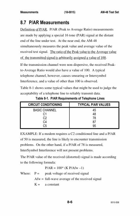
Measurements (18-0015) AM-48 Test Set
0015-S088-6
8.7 P/AR MeasurementsDefinition of P/AR . P/AR (Peak to Average Ratio) measurements
are made by applying a special 16 tone (PAR) signal at the distant
end of the line under test. At the near end, the AM-48
simultaneously measures the peak value and average value of the
received test signal. The ratio of the Peak value to the Average value
of the transmitted signal is arbitrarily assigned a value of 100 .
If the transmission channel were non-dispersive, the received Peak-
to-Average Ratio would also have a value of 100. A typical
telephone channel, however, causes smearing or Intersymbol
Interference, and a value of other than 100 is observed.
Table 8-1 shows some typical values that might be used to judge the
acceptability of a telephone line to reliably transmit data.
Table 8-1. P/AR Requirements of Telephone Lines
CIRCUIT CONDITIONING TYPICAL P/AR VALUES
BASIC CHANNELC1C2C4C5
4548788795
EXAMPLE: If a modem requires a C2 conditioned line and a P/AR
of 50 is measured, the line is likely to encounter transmission
problems. On the other hand, if a P/AR of 78 is measured,
InterSymbol Interference will not present problems.
The P/AR value of the received (distorted) signal is made according
to the following formula:
P/AR = 100* (K P/Afw –1)
Where: P = peak voltage of received signal
Afw = full-wave average of the received signal
K = a constant
AM-48 Test Set (18-0015) Measurements
0015-S08 8-7
The constant K is derived by giving an undistorted signal a nominal
value of 100. Therefore:
K = 2Safwo/Po
Where: Po = Peak voltage of the undistorted (original) signal
Afwo = full-wave average of the undistorted (original)
signal
Therefore: P/AR = 100 * (2(P/Po)/(Afw/Afwo)-1)
or P/AR = 100 * (2(Pn/Afwn)-1)
Where: Pn = normalized peak voltage of the received signal
Afwn = normalized full-wave average of the received signal
Factors Which Affect P/AR . P/AR is most sensitive to envelope
delay distortion and return loss problems. To a lesser degree, it is
affected by attenuation distortion, noise, and nonlinear
(intermodulation) distortion. It is basically unaffected by transient
phenomena, such as impulse noise and phase and gain hits.
Envelope Delay Distortion . There is a high correlation between
measured P/AR values and values calculated from a plot of envelope
delay distortion. In fact, for an envelope delay response containing
significant ripples, P/AR is a better indication of the ability of the
network to pass data reliably. Return loss problems are a common
source of envelope delay ripple.
Effect of Noise . Noise can have a significant effect on a P/AR
measurement. For this reason, it is important to measure signal to
noise ratio (or noise-with-tone) before making a P/AR measurement.
If the signal-to-noise ratio is less than 25 dB, the P/AR reading will
be significantly reduced by noise alone.
Measurements (18-0015) AM-48 Test Set
0015-S088-8
Effect of Nonlinear Distortion . Nonlinear (Intermodulation)
Distortion can similarly affect the P/AR reading. The effect depends
on whether the second or third order products dominate as the source
of the distortion. If the third order products dominate, they increase
or decrease the P/AR value, depending upon the sign of the added
products.
8.8 Gain SlopeGain slope (sometimes referred to as attenuation distortion)
measurements are similar to a level/frequency measurement, except
that the level measurement is made at several different frequencies in
order to determine the loss (or gain) on the line at different
frequencies. The AM-48 SEND 3TONE will repeatedly send 5-second
intervals each of 404 Hz, 1004 Hz, and 2804 Hz. The AM-48E SEND
SLOPE will repeatedly send 5-second intervals each of 404 Hz, 1004
Hz, 2004 Hz, and 3004 Hz.
Because it is desirable to express the difference in loss at different
frequencies, this measurement is usually done on a relative level
basis. The two (2) methods that can be used with the AM-48 to
measure gain slope are outlined below:
Gain Slope Using <ABS> Measure .
1. Set Switch 2 of near end AM-48 to <ABS>.
2. Read the level at the near end of the line while the far end
AM-48 is in SEND 3TONE (SLOPE for AM-48E).
3. Note the least loss and most loss readings.
4. Calculate the difference between the least loss and most loss
readings. This is the gain slope of the line.
AM-48 Test Set (18-0015) Measurements
0015-S08 8-9
Gain Slope Using <REL> Measure .
1. Start with Switch 2 of near end AM-48 to <ABS>.
2. Read the level at the near end of the line while the far end
AM-48 is in SEND 3TONE (SLOPE for AM-48E).
3. Note the lowest absolute reading.
4. Set Switch 2 to <REL> when the display shows the lowest
absolute reading.
5. The display will initially read zero, and all subsequent readings
will be in DB REL, relative to the lowest absolute reading.
8.9 Idle Channel Impulse NoiseThis is a timed study that counts the number of noise pulses that
exceed each of three levels (thresholds). No Holding Tone is used
for this test. The constraints of the test are first set up and then the
test is run.
Information concerning the idle channel impulse noise test
1. Three (3) noise thresholds are established> low , middle , and
high levels, with an equal interval between them, called the
delta .
2. The time over which the run is to be made is set, called the
duration .
3. The run is started, and a running count is kept of the number of
noise pulses that exceed each threshold.
4. The run will automatically stop when the duration time is
reached, or the test can be manually stopped at any previous
time.
5. A blanking interval is set, during which time the noise pulse
counter does not count.
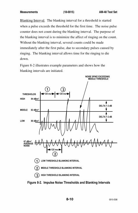
Measurements (18-0015) AM-48 Test Set
0015-S088-10
Blanking Interval . The blanking interval for a threshold is started
when a pulse exceeds the threshold for the first time. The noise pulse
counter does not count during the blanking interval. The purpose of
the blanking interval is to minimize the affect of ringing on the count.
Without the blanking interval, several counts could be made
immediately after the first pulse, due to secondary pulses caused by
ringing. The blanking interval allows time for the ringing to die
down.
Figure 8-2 illustrates example parameters and shows how the
blanking intervals are initiated.
NOISE SPIKE EXCEEDINGMIDDLE THRESHOLD
THRESHOLDS
LOW THRESHOLD BLANKING INTERVAL
MIDDLE THRESHOLD BLANKING INTERVAL
HIGH THRESHOLD BLANKING INTERVAL
125 ms
HIGH
MIDDLE
AVERAGENOISE
LOW
84 dBrn*
82 dBrn*
80 dBrn*
67 dBrn*
DELTA = 2 dB
DELTA = 2 dB
125 ms
125 ms
1
2
2
3
1
3
Figure 8-2. Impulse Noise Thresholds and Blanking Intervals
AM-48 Test Set (18-0015) Measurements
0015-S08 8-11
See the tables in Figure 7-6 for information on the ranges of the
parameters. A typical duration time for the study is 15 minutes,
although a study of up to 33 hours could be made. Note that only
values for the low level and the delta are set, which determines all
three (3) levels.
8.10 Phase JitterThis measurement requires a 1004 Hz nominal Holding Tone. This
test measures the peak-to-peak phase variation of the modulation of
the holding tone. The bandpass (range of frequencies) is selected,
over which the phase jitter is to be measured. A phase-locked-loop
generator locks on to the Holding Tone and an average peak-to-peak
phase jitter is measured in degrees.
The bandpass (bandwidth) can be set to either:
• 4 Hz to 300 Hz or
• 20 Hz to 300 Hz
The exact frequency of the Holding Tone is known because it is the
same as the displayed phase-locked-loop frequency.
8.11 Amplitude JitterThe test setup for amplitude jitter is the same as the phase jitter
measurement (¶8.10) except that instead of measuring the variation of
the phase, the variation of the amplitude of the modulation is
measured. The unit of measurement for the amplitude jitter is
average percent peak-to-peak variation.
Since this is an amplitude measurement, the phase-locked-loop
frequency is not of interest.
Measurements (18-0015) AM-48 Test Set
0015-S088-12
8.12 Notched Impulse NoiseThis test is the same as the Idle Channel Impulse Noise Test, ¶8.9,
except that it is made over an active line with a holding tone which is
notched out before the measurements are performed.
8.13 Phase HitsA phase hit is a sudden change in the phase of the modulation of a
Holding Tone. A threshold of from 5 to 45 degrees is set, and the
number of phase hits that exceed that threshold during the timed
study is counted.
8.14 Gain HitsA gain hit is a sudden change in the amplitude of the modulation of a
Holding Tone. A threshold of 2, 3, 4, or 6 dB is set, and the number
of gain hits that exceed that threshold during the timed study is
counted.
8.15 DropoutsA dropout is the loss of the Holding Tone. The number of losses of
the Holding Tone during a timed study is counted. A “loss” of the
Holding Tone occurs if the Holding Tone level and/or frequency go
out of the acceptable range for valid transient measurements.
AM-48 Test Set (18-0015) Circuit Diagrams
0015-S09 9-1
9. CIRCUIT DIAGRAMS
9.1 IntroductionThis section covers a block diagram of the AM-48 and a schematic
diagram of the Impedance Adapter.
9.2 AM-48 Simplified Block DiagramFigure 9-1 is a simplified block diagram of the AM-48. Note that
continuous lines connecting the blocks indicate signal paths, while
broken lines indicate control paths. The definitions of the
abbreviations in the block diagram are listed below.
AMP AMPlifier AV Average detector
AUTO AUTOmatic BP 1 KHz Band Pass filter
CMSG C-message noise-weighting filter
DET DETector FILT FILTer
FWR Full Wave Rectifier HOLD HOLDing circuit
4 HZ 4 Hz high pass filter 20 HZ 20 Hz high pass filter
300 HZ 300 Hz low pass filter IMPLS IMPuLSe
MIC MICrophone MUX MultipleXor
NTCH 1010 Hz NoTCH filter
PAR Peak-to-Average Ratio filter (1300 Hz bandpass)
PK PeaK detector P/P Peak-to-Peak detector
PROG PROGram noise-weighting filter
QUIET QUIET termination R Ring
RCV ReCeiVe
RMS RMS (Root Mean Square) detector (for noise)
SKR SpeaKeR SND SeND
SW Switch T Tip
V/F Voltage-to-Frequency converter
2W 2-Wire 4W $-Wire
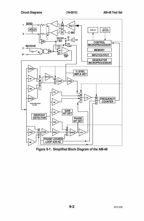
Circuit Diagrams (18-0015) AM-48 Test Set
0015-S099-2
FILTHOLD
SEND
MIC
MUX
MUX
MUX
MUX
MUX
MUX
MUX
2W
4W
T
R
RECEIVECONTROL
MEMORY
INPUT/OUTPUT
GENERATOR
MICROPROCESSOR
MICROPROCESSOR
FREQUENCYCOUNTER
3 LEVELIMPLS DET
DROPOUTDETECTOR
GAIN
CMSG
NTCH
AMP RMS
PK
AV
AV
4HZ
20HZ 300HZ P/P
V/F
FWR
3K
15K
PROG
PAR
NOISE-WEIGHTINGFILTERS
BP
HIT DET
PHASE LOCKEDLOOP 4/20 HZ
T1
R1
<MON SND>
<OFF><2W>
<4W>
<MON RCV>
SKR
DISPLAYKEYPAD
SWITCHES
SW 14
SW3
<DAMP>
SW10 AUTORANGE AMP
PHASEHIT DET
Figure 9-1. Simplified Block Diagram of the AM-48
AM-48 Test Set (18-0015) Circuit Diagrams
0015-S09 9-3
9.3 Impedance Adapter SchematicFigure 9-2 is a schematic diagram of the Impedance Adapter, Model
Number 24-0008.
See Figure 3-10 for an illustration of the Impedance Adapter. Also
see ¶3.10, ¶6.5, and ¶7.41 concerning the Impedance Adapter.
Note the following in the schematic shown in Figure 9-2:
1. The upper circuitry (2W or 4W Send) is identical to the lower
circuitry (4W Receive).
2. Switch S1 is controlled by the upper knob of the Impedance
Adapter; Switch S2 is controlled by the lower knob.
3. Impedance Adapter switch positions (THRU, 1200, 900, 150,
135, and 75) are indicated on the upper poles of S1 and S2.
4. The internal impedance of the AM-48 is set for 600 Ohms.
Therefore, for impedance greater than 600 Ohms , the Impedance
Adapter adds resistance in series to give the correct impedance.
For impedance less than 600 Ohms , the Impedance Adapter
connects an appropriate resistance in parallel to give the correct
impedance.
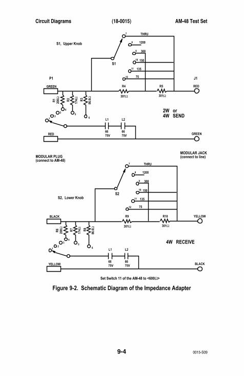
Circuit Diagrams (18-0015) AM-48 Test Set
0015-S099-4
S1, Upper Knob
2W or4W SEND
P1
S1
J1
GREEN
GREEN
RED
RED
R4
L1 L2
66 6675V 75V
R2 R3
174Ω
86.6
Ω
R1
200Ω
301Ω 301Ω
R5
THRU
1200
300
150
135
75
7
12
34
56
8
9
10
11
12
S2, Lower Knob
Set Switch 11 of the AM-48 to <600Ω>
MODULAR PLUG(connect to AM-48)
MODULAR JACK(connect to line)
4W RECEIVE
S2
BLACK
BLACK
YELLOW
YELLOW
R9
L1 L2
66 6675V 75V
R7 R8
174Ω
86.6
Ω
R6
200Ω
301Ω 301Ω
R10
THRU
1200
300
150
135
75
7
12
34
56
8
9
10
11
12
Figure 9-2. Schematic Diagram of the Impedance Adapter
AM-48 Test Set (18-0015) Warranty
0015-S10 10-1
10. WARRANTY, SERVICE, & CALIBRATION10.1 WarrantyAMERITEC Corporation warrants that its electronic instrument
products are manufactured to the highest commercial standards and
are free from any defects in material or workmanship.
For a period of one (1) year from shipment, AMERITEC will repair,
without charge to the original purchaser, any unit which upon
inspection by AMERITEC proves to be defective.
This warranty is the sole warranty offered by AMERITEC and is in
lieu of all other obligations or liabilities, including claims of
consequential damage; however, an EXTENDED WARRANTY
PLAN may be purchased. For information contact an AMERITEC
Sales Representative.
10.2 Service PolicyAMERITEC products are designed with plug-in printed circuit
boards and modular assemblies. Once a problem is localized, service
is accomplished by PC board (or module) replacement.
10.3 Calibration PolicyAll AMERITEC products are manufactured to commercial standards
and are calibrated with equipment traceable to NIST (National
Institute of Standards and Technology). With the exception of
component failures or abuse, AMERITEC instruments are designed
to maintain compliance with their published specifications
throughout their service life.
While periodic calibration verification is normally not required, in
critical applications it is recommended that verification be
accomplished annually.
Warranty (18-0015) AM-48 Test Set
0015-S1010-2
Calibration verification is most efficiently accomplished by return of
the equipment to the AMERITEC factory where specialized test
equipment is used. Field calibration verification is not supported by
AMERITEC.
10.4 Return of UnitIn the event of a malfunction, call or write to the AMERITEC factory
and obtain a return authorization number.
Return the unit to AMERITEC, freight prepaid, with a note (in-
warranty repair) or a Purchase Order for the repair (out-of-warranty
repair) listing the following information:
• Return authorization number from AMERITEC.
• Return shipment address of purchaser.
• Name and telephone number of person at purchaser’s
location who is familiar with the problem.
• Brief description of problem. (Include any printouts that
may have a bearing on the problem, if possible.)
• Terms of payment of repair costs (out-of-warranty unit).
The unit will be repaired and returned freight-prepaid for units in
warranty and freight-collect for out-of-warranty units.
As stated above, a Purchase Order to cover the cost of repair must
accompany any out-of-warranty return of the unit to AMERITEC.
760 Arrow Grand CircleCovina, CA 91722 USA
TEL 626.915.5441FAX 626.915.7181www.ameritec.com
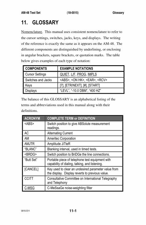
AM-48 Test Set (18-0015) Glossary
0015-S11 11-1
11. GLOSSARY
Nomenclature . This manual uses consistent nomenclature to refer to
the cursor settings, switches, jacks, keys, and displays. The writing
of the reference is exactly the same as it appears on the AM-48. The
different components are distinguished by underlining, or enclosing
in angular brackets, square brackets, or quotation marks. The table
below gives examples of each type of notation:
COMPONENTS EXAMPLE NOTATIONS
Cursor Settings QUIET, L/F, PROG, IMPLS
Switches and Jacks <ABS>, <ON HK>, <EAR>, <RCV>
Keys [7], [ETR/NEXT], [#], [START]
Displays “LEVL”, “-10.0 DBM”, “400 HZ”
The balance of this GLOSSARY is an alphabetical listing of the
terms and abbreviations used in this manual along with their
definitions.
ACRONYM COMPLETE TERM or DEFINITION
<ABS> Switch position to give ABSolute measurementreadings.
AC Alternating Current
AM Ameritec Corporation
AMJTR Amplitude JiTteR
“BLANC” Blanking interval, used in timed tests.
<BRDG> Switch position to BriDGe the line connections.
“Butt Set” Portable piece of telephone test equipment withcapability of dialing, talking, and listening.
[CANCEL] Key used to clear an undesired parameter value fromthe display. Display reverts to previous value.
CCITT Consultative Committee on International Telegraphyand Telephony
C-MSG C-MeSsaGe noise-weighting filter
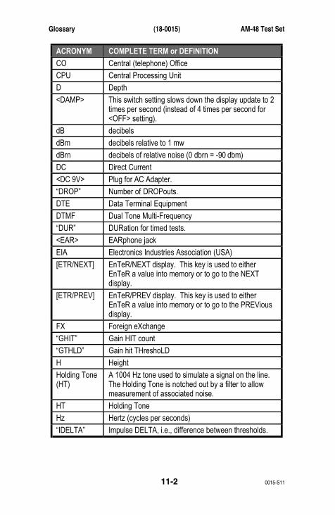
Glossary (18-0015) AM-48 Test Set
0015-S1111-2
ACRONYM COMPLETE TERM or DEFINITION
CO Central (telephone) Office
CPU Central Processing Unit
D Depth
<DAMP> This switch setting slows down the display update to 2times per second (instead of 4 times per second for<OFF> setting).
dB decibels
dBm decibels relative to 1 mw
dBrn decibels of relative noise (0 dbrn = -90 dbm)
DC Direct Current
<DC 9V> Plug for AC Adapter.
“DROP” Number of DROPouts.
DTE Data Terminal Equipment
DTMF Dual Tone Multi-Frequency
“DUR” DURation for timed tests.
<EAR> EARphone jack
EIA Electronics Industries Association (USA)
[ETR/NEXT] EnTeR/NEXT display. This key is used to eitherEnTeR a value into memory or to go to the NEXTdisplay.
[ETR/PREV] EnTeR/PREV display. This key is used to eitherEnTeR a value into memory or to go to the PREViousdisplay.
FX Foreign eXchange
“GHIT” Gain HIT count
“GTHLD” Gain hit THreshoLD
H Height
Holding Tone(HT)
A 1004 Hz tone used to simulate a signal on the line.The Holding Tone is notched out by a filter to allowmeasurement of associated noise.
HT Holding Tone
Hz Hertz (cycles per seconds)
“IDELTA” Impulse DELTA, i.e., difference between thresholds.
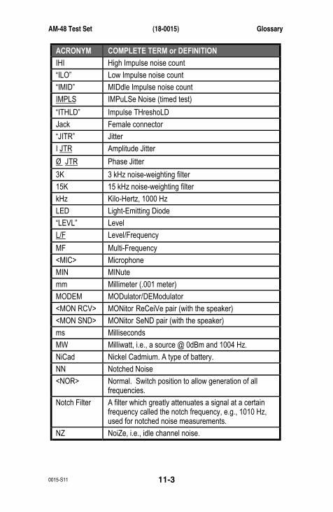
AM-48 Test Set (18-0015) Glossary
0015-S11 11-3
ACRONYM COMPLETE TERM or DEFINITION
IHI High Impulse noise count
“ILO” Low Impulse noise count
“IMID” MIDdle Impulse noise count
IMPLS IMPuLSe Noise (timed test)
“ITHLD” Impulse THreshoLD
Jack Female connector
“JITR” Jitter
I JTR Amplitude Jitter
Ø JTR Phase Jitter
3K 3 kHz noise-weighting filter
15K 15 kHz noise-weighting filter
kHz Kilo-Hertz, 1000 Hz
LED Light-Emitting Diode
“LEVL” Level
L/F Level/Frequency
MF Multi-Frequency
<MIC> Microphone
MIN MINute
mm Millimeter (.001 meter)
MODEM MODulator/DEModulator
<MON RCV> MONitor ReCeiVe pair (with the speaker)
<MON SND> MONitor SeND pair (with the speaker)
ms Milliseconds
MW Milliwatt, i.e., a source @ 0dBm and 1004 Hz.
NiCad Nickel Cadmium. A type of battery.
NN Notched Noise
<NOR> Normal. Switch position to allow generation of allfrequencies.
Notch Filter A filter which greatly attenuates a signal at a certainfrequency called the notch frequency, e.g., 1010 Hz,used for notched noise measurements.
NZ NoiZe, i.e., idle channel noise.

Glossary (18-0015) AM-48 Test Set
0015-S1111-4
ACRONYM COMPLETE TERM or DEFINITION
<OFF> This is the normal switch setting to give a displayupdate of 4 times per second.
<ON HK> Switch position for ON HooK.
“OVER” Level is OVER maximum measurable level.
PAR Peak-to-Average Ratio
PHJTR Phase JiTteR
“PLL” Phase-Locked Loop frequency
Plug Male connector
P/P Peak-to-Peak
PPS Pulses Per Second
<PRINT> Print. Switch position to give printed copy of setup andmeasurements.
PROG PROGram noise-weighting filter. This term comesfrom radio broadcasting where a PROGram filter wasdeveloped to simulate the effect of transmitting a radioPROGram to a remote transmission tower.
<PRT> Printer port jack.
PSHO PsopHOmetric noise-weighting filter
“PTHLD” Phase hit ThreshoLD
<PULSE> Switch position for PULSE dialing.
QUIET Quiet termination
R, R1 Ring: the connection at the ring of e.g., a Bantamconnector.
“RANGE” Frequency bandwidth RANGE for jitter measurements.
<RCL/STO> ReCaLl/STOre. Switch position to store/recallinformation from non-volatile memory.
<RCV> ReCeiVe jack
Ref Reference
<REL> Switch position to give RELative measurementreadings.
RJ11 6-wide modular connector
RS232 Standard EIA interface using 25-pin D connector.
<SEL> SELect

AM-48 Test Set (18-0015) Glossary
0015-S11 11-5
ACRONYM COMPLETE TERM or DEFINITION
<SEND> Switch position to monitor SEND signal on display.
<SF SKP> Signaling Frequency SKIP. Switch position to preventgeneration of tones in the signaling band.
<SHIFT> Switch position to enable auxiliary keyboard functions.
SLOPE For AM-48E only, pre-programmed set of tones (304Hz, 1004 Hz, 2004 Hz, 3004 Hz) which are sent in acycle for 5 second intervals. See 3TONE for AM-48.
S/N Signal-to-Noise ratio
<SND> SeND jack
S/S Starting and Stopping of a timed test.
[START] Key used to start a timed test.
[STOP] Key used to stop a timed test.
“STUC” Stuck. Display indication that sweep is programmedfor only one frequency.
SWEEP A programmable series of frequencies are sent insteps.
SWTD Sound-WeighTeD noise-weighting filter
T, T1 Tip. The connection at the tip of e.g., a Bantamconnector.
<TALK> “Push-to-TALK” switch
<TERM> TERMinate: switch position to terminate lineconnections.
THLD ThreshoLD
“THLD 2 HI” Display indication that upper ThreshoLD is too High (inimpulse noise timed test).
TIE TIE line of a telephone network.
“TIME” Elapsed time for timed tests.
“TMOFF” TiMe OFF. Time after which AM-48 will automaticallyturn itself off when unit is left unattended.
3TONE For AM-48 only, pre-programmed set of tones (404 Hz,1004 Hz, 2804 Hz) which are sent in a cycle for 5second intervals. See SLOPE for AM-48E.
TRAN TRANsient test
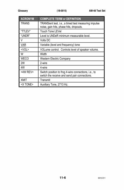
Glossary (18-0015) AM-48 Test Set
0015-S1111-6
ACRONYM COMPLETE TERM or DEFINITION
TRANS TRANSient test, i.e., a timed test measuring impulsenoise, gain hits, phase hits, dropouts.
“TTLEV” Touch Tone LEVel
“UNDR” Level is UNDeR minimum measurable level.
V Volts DC
VAR Variable (level and frequency) tone
<VOL> VOLume control. Controls level of speaker volume.
W Width
WECO Western Electric Company
2W 2-wire
4W 4-wire
<4W REV> Switch position to frog 4-wire connections, i.e., toswitch the receive and send pair connections.
XMIT Transmit
<X TONE> Auxiliary Tone, 2713 Hz.
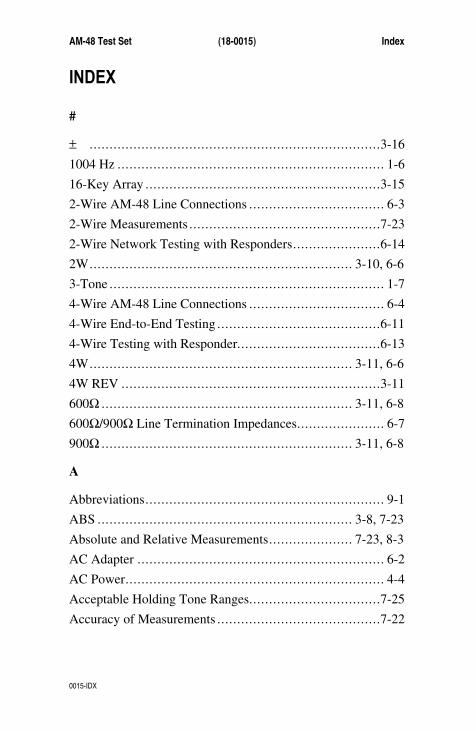
AM-48 Test Set (18-0015) Index
0015-IDX
INDEX
#
± .........................................................................3-16
1004 Hz ................................................................... 1-6
16-Key Array ...........................................................3-15
2-Wire AM-48 Line Connections .................................. 6-3
2-Wire Measurements ................................................7-23
2-Wire Network Testing with Responders......................6-14
2W.................................................................. 3-10, 6-6
3-Tone ..................................................................... 1-7
4-Wire AM-48 Line Connections .................................. 6-4
4-Wire End-to-End Testing .........................................6-11
4-Wire Testing with Responder....................................6-13
4W.................................................................. 3-11, 6-6
4W REV .................................................................3-11
600Ω ............................................................... 3-11, 6-8
600Ω/900Ω Line Termination Impedances...................... 6-7
900Ω ............................................................... 3-11, 6-8
A
Abbreviations............................................................ 9-1
ABS ................................................................ 3-8, 7-23
Absolute and Relative Measurements..................... 7-23, 8-3
AC Adapter .............................................................. 6-2
AC Power................................................................. 4-4
Acceptable Holding Tone Ranges.................................7-25
Accuracy of Measurements .........................................7-22

Index (18-0015) AM-48 Test Set
0015-IDXI-2
ALKALINE.............................................................. 4-2
Alkaline Batteries....................................................... 4-3
AM-47 Hand-Held Printer Connection with AC Power...... 6-5
AM-47 Hand-Held Printer Technical Specifications.........3-21
AM-48 Auto Calibrate Prompts ...................................7-60
AM-48 Connectors..................................................... 3-4
AM-48 General Technical Specifications........................ 1-5
AM-48 Generator (Send) Technical Specifications ........... 1-6
AM-48 Interface with Line Connections ......................... 6-6
AM-48 Keyboard Identification Numbers ......................3-15
AM-48 Liquid Crystal Display ....................................3-18
AM-48 Location of Components................................... 3-3
AM-48 Optional Equipment......................................... 2-2
AM-48 Polarity ......................................................... 6-6
AM-48 Power/Physical Technical Specifications.............1-11
AM-48 Receiver (Measure) Technical Specifications ........ 1-8
AM-48 SEND, MEASURE, and FILTER Menus ............3-19
AM-48 Setup for Self-Test (Looped Back)...................... 5-2
AM-48 Simplified Block Diagram................................. 9-1
AM-48 Standard Equipment......................................... 2-2
AM-48 Switch Identification Numbers ........................... 3-6
AM-48 Technical Specifications ................................... 1-4
AM-48E Technical Specifications ................................1-11
Amplitude Jitter ................................................. 1-9, 8-11
Auto Calibrate ..........................................................7-59
Auto Study Result Save..............................................7-56
Automatic Power Shutdown......................................... 4-4
Aux Tone ................................................................. 1-7
Auxiliary Functions...................................................3-14
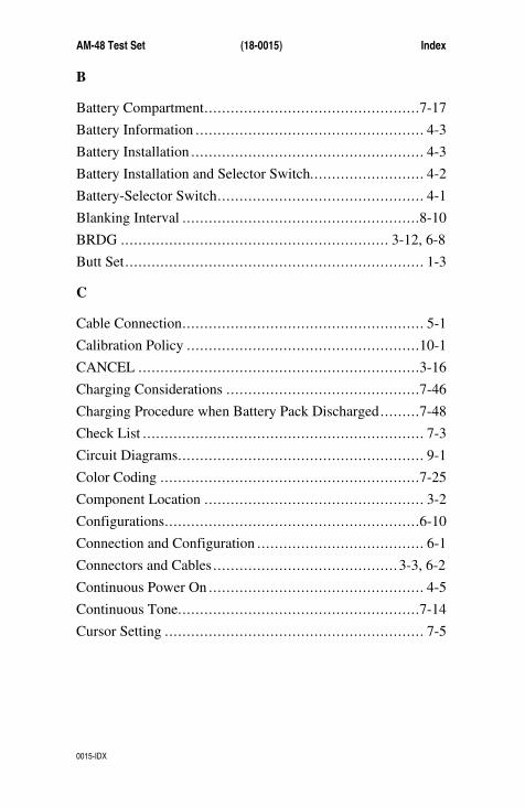
AM-48 Test Set (18-0015) Index
0015-IDX
B
Battery Compartment.................................................7-17
Battery Information .................................................... 4-3
Battery Installation ..................................................... 4-3
Battery Installation and Selector Switch.......................... 4-2
Battery-Selector Switch............................................... 4-1
Blanking Interval ......................................................8-10
BRDG ............................................................. 3-12, 6-8
Butt Set.................................................................... 1-3
C
Cable Connection....................................................... 5-1
Calibration Policy .....................................................10-1
CANCEL ................................................................3-16
Charging Considerations ............................................7-46
Charging Procedure when Battery Pack Discharged.........7-48
Check List ................................................................ 7-3
Circuit Diagrams........................................................ 9-1
Color Coding ...........................................................7-25
Component Location .................................................. 3-2
Configurations..........................................................6-10
Connection and Configuration ...................................... 6-1
Connectors and Cables .......................................... 3-3, 6-2
Continuous Power On ................................................. 4-5
Continuous Tone.......................................................7-14
Cursor Setting ........................................................... 7-5

Index (18-0015) AM-48 Test Set
0015-IDXI-4
D
DAMP ..................................................................... 3-8
Damping .................................................................1-10
dB........................................................................... 8-2
dBm ........................................................................ 8-2
dBrn ........................................................................ 8-3
Default Parameter Settings for SWEEP Send Mode .........5-14
Definition and Purpose................................................ 1-2
Dial ......................................................................... 1-5
Dialing......................................................5-8, 5-10, 7-43
Dimensions............................................................... 3-1
Display ............................................................ 3-17, 7-3
Display Damping Switch ............................................. 7-7
Display Fields ........................................................... 7-4
Display Select Switch ................................................. 3-8
Distortion ................................................................. 1-7
Down Arrow............................................................3-17
Dropouts .................................................................8-12
Dry Circuit Measurements ........................................... 6-1
DTMF ..................................................................... 3-9
E
Earphone.................................................................. 6-2
Effect of Noise .......................................................... 8-7
Effect of Nonlinear Distortion ...................................... 8-8
End-to-End Testing ...................................................6-10
Envelope Delay Distortion........................................... 8-7
ETR/NEXT..............................................................3-16
AM-48 Test Set (18-0015) Index
0015-IDX
ETR/PREV..............................................................3-16
Explanation and Application of Measurements ................ 8-1
F
Far End .................................................................... 8-4
Figure Format............................................................ 7-4
Filter Select Switch .................................................... 3-9
Front Panel/Switches Color Coding ............................... 3-2
Functional Overview .................................................. 1-3
G
Gain Hits.................................................................8-12
Gain Slope................................................................ 8-8
General .................................................. 3-1, 4-1, 5-1, 6-1
General Description.................................................... 1-2
General Instructions and Notes ..................................... 7-3
General Instructions and Notes for MEASURE Modes.....7-22
General Operating Notes ............................................. 7-3
General Procedure to Set New Parameter Values.............7-12
General Switch Setup............................................ 5-3, 7-6
General Switch Setup for Self Test ................................ 5-3
Glossary..................................................................11-1
H
Hand-Held Printer .....................................................3-20
Hand-Held Printer, External View................................3-22
Hand-Held Printer, Internal View.................................3-23
Holding.................................................................... 1-5
Holding Tone ............................................................ 8-5

Index (18-0015) AM-48 Test Set
0015-IDXI-6
Holding Tone Ranges ................................................7-25
I
Idle Channel Impulse Noise ......................................... 8-9
Idle Channel Noise ..................................................... 8-4
Impedance Adapter ............................................ 3-24, 6-9
Impedance Adapter Correction Value Memory Aid .........7-58
Impedance Adapter Correction Values ..........................7-57
Impedance Adapter Measurement Corrections ................7-56
Impedance Adapter Schematic...................................... 9-3
Impedances............................................................... 1-5
IMPLS MEASURE Displays.......................................7-32
Impulse Noise ........................................................... 1-9
Impulse Noise Thresholds and Blanking Intervals ...........8-10
Independent Send and Measure Modes........................... 6-2
Information Table ...................................................... 7-5
Inspection when Received ........................................... 2-1
Introduction ..........................1-1, 2-1, 3-1, 6-1, 7-1, 8-1, 9-1
K
Keyboard.................................................................3-14
Keys........................................................................ 7-3
Keys with Two (2) Auxiliary Functions.......................... 7-8
L
L/F, NOISE, and PAR MEASURE Displays ..................7-28
Level (Loss of Gain) and Frequency .............................. 8-4
Level and Noise Units of Measurement .......................... 8-2
Level Display...........................................................7-10
AM-48 Test Set (18-0015) Index
0015-IDX
Level/Freq................................................................ 1-8
Line Connection Cables .............................................. 6-3
Listen .....................................................................7-45
Loopback Testing......................................................6-11
Low-Level Noise Measurements ............................. 4-1, 6-1
M
Main Display Field....................................................3-17
Manual Overview....................................................... 1-1
Measure Amplitude Jitter............................................7-35
Measure Dropouts .....................................................7-38
Measure Gain Hits ....................................................7-37
Measure Impulse Noise ..............................................7-29
Measure Level and Frequency .....................................7-27
MEASURE Modes....................................................7-27
Measure Noise..........................................................7-28
Measure Notched Impulse Noise..................................7-36
Measure Notched Noise .............................................7-32
Measure PAR...........................................................7-29
Measure Phase Hits ...................................................7-37
Measure Phase Jitter ..................................................7-34
MEASURE Printouts, Absolute Measure Mode ..............7-54
MEASURE Printouts, Relative Measure Mode ...............7-55
Measure S/N Ratio ....................................................7-34
Measure Select Switch ................................................ 3-9
Measure Transients ...................................................7-36
Measurements ........................................................... 1-5
Memory ................................................................... 7-9
Memory Aid ............................................................7-57
Index (18-0015) AM-48 Test Set
0015-IDXI-8
Menu Color Coding and Framing .................................3-18
Menu Framing..........................................................7-25
Menus.....................................................................3-18
MF.......................................................................... 3-9
MF and DTMF Tone Pairs ..........................................7-44
Microphone/Speaker..................................................3-19
Miscellaneous Operations ...........................................7-40
Momentary Tone ......................................................7-14
MON RCV ..............................................................3-13
MON SND ..............................................................3-13
Multi-Function Keyboard ............................................ 7-8
Multiple Use of Keys.................................................. 7-8
N
Near End .................................................................. 8-5
NICAD .................................................................... 4-2
NiCad Batteries ......................................................... 4-4
Noise....................................................................... 1-8
Nomenclature...........................................................11-1
Non-Volatile Memory......................................... 7-9, 7-11
NOR.......................................................................3-10
Normal Charging Procedure........................................7-47
Notched Impulse Noise ..............................................8-12
Notched Noise........................................................... 1-8
Notched Noise (Noise with Tone) ................................. 8-4
Notched Noise and S/N Ratio MEASURE Displays.........7-33
Notes....................................................................... 7-5

AM-48 Test Set (18-0015) Index
0015-IDX
O
ON HK ...................................................................3-12
Operating Instructions................................................. 7-1
Optional AM-48 Cables .............................................. 3-5
P
P/AR Measurements ................................................... 8-6
P/AR Requirements of Telephone Lines ......................... 8-6
Paper Roll Compartment ............................................3-23
Paper Roll Installation........................................3-23, 7-45
PAR .................................................................. 1-7, 1-8
Parameter Settings from 1004 Hz andVAR Tone Displays..............................................7-18
Parameter Settings from 3-Tone Slope andPAR SEND Displays ............................................7-20
Parameter Settings from QUIET SEND Display..............7-15
Parameter Settings from SWEEP SEND Display.............7-21
Parameter Values for Send Sweep ................................5-10
Parameter Values Stored in Memory.............................. 7-9
Phase Hits................................................................8-12
Phase Jitter ....................................................... 1-9, 8-11
Phase JTR and Amplitude JTR MEASURE Displays .......7-35
Physical ..................................................................1-11
Physical and Functional Description .............................. 3-1
Power .....................................................................1-11
Power Considerations ................................................. 4-1
Power Off................................................................. 4-5
Power On/Off Switch............................................ 3-7, 4-4
PRINT ....................................................................3-10

Index (18-0015) AM-48 Test Set
0015-IDXI-10
Printer...................................................................... 1-6
Printer Cables............................................................ 6-3
Printer Connectors.....................................................3-20
Printer LEDs............................................................3-20
Printer Power ...........................................................3-20
Printer Power Switch .................................................3-20
Printer Self Test........................................................7-46
Printing...................................................................7-45
Printing Mechanism...................................................3-21
PULSE ...................................................................3-12
Q
Quiet ....................................................................... 1-7
Quiet Send Mode ....................................................... 5-4
Quiet Send Mode Self Test .......................................... 5-4
R
RCL/STO................................................................3-10
Recall .....................................................................7-41
Recall and Store Operations ........................................7-42
Receiving and Unpacking ............................................ 2-1
REL ................................................................ 3-8, 7-23
Return of Unit ..........................................................10-2
Ribbon Cartridge Replacement ....................................7-48
Rocker Switches ........................................................ 3-7
S
S/N Ratio ................................................................. 1-8
Schematic Diagram of the Impedance Adapter................. 9-4
AM-48 Test Set (18-0015) Index
0015-IDX
Scroll Through Displays.............................................7-12
Self-Test Instructions.................................................. 5-1
Self-Test Setup .......................................................... 5-1
SEND...................................................................... 3-8
Send (Generator) Modes and Parameter Settings .............7-13
Send 1004 Hz.................................................... 5-5, 7-18
Send 1004 Hz Self Test, Displays.................................. 5-7
Send 1004 Hz Self Test, Switch Settings......................... 5-6
Send Continuous Variable Tone...................................7-19
Send Momentary 2713 Hz Tone...................................7-22
Send Momentary Variable Tones .................................7-17
Send PAR (Peak-to-Average Ratio) ......................... 5-7, 5-8
Send PAR Waveform.................................................7-22
SEND Printouts ........................................................7-52
Send Quiet...............................................................7-14
Send Select Switch..................................................... 3-9
Send Set of Slope Tones.............................................7-19
Send Variable Sweep .................................................7-20
Service Policy ..........................................................10-1
Set Blanking Interval .................................................7-17
Set Level .................................................................7-16
Set Parameters from Quiet Display ...............................7-15
Set Time Off ............................................................7-16
Set Touch Tone Level ................................................7-16
Set Up to 10 Frequencies ............................................7-16
Setup Requirements for Dialing ...................................7-44
Setup Requirements for Different Keyboard Applications .. 7-8
SF Skip ............................................................ 1-7, 3-10
SHIFT ..................................................................... 3-9
Index (18-0015) AM-48 Test Set
0015-IDXI-12
Signal-to-Noise (S/N) Ratio ......................................... 8-5
Simplified Block Diagram of the AM-48 ........................ 9-2
Slide Switches ........................................................... 3-7
Speaker Control ........................................................3-13
Special Measurement Requirements......................7-24, 7-26
Standard AM-48 Cables .............................................. 3-4
START ...................................................................3-17
Steps for Up and Down Arrow Keys .............................. 7-9
STOP......................................................................3-17
Store.......................................................................7-41
Store and Recall........................................................7-40
Store/Recall ...................................................... 1-6, 7-10
Sweep...................................................................... 1-7
Switch 11 Settings...................................................... 6-8
Switch 13 Settings...................................................... 6-8
Switch Settings.......................................................... 7-5
Switches................................................................... 3-5
T
Talk..........................................................1-5, 3-13, 7-45
Talking ...................................................................7-45
TERM ............................................................. 3-12, 6-8
Term/Bridge ............................................................1-10
Testing Configurations................................................ 1-4
Testing with Responders.............................................6-12
Thumb Wheel............................................................ 3-7
Timed Tests .............................................................7-26
TONE.....................................................................3-11
TRANS MEASURE Displays .............................7-39, 7-40

AM-48 Test Set (18-0015) Index
0015-IDX
Transient Measurements.............................................. 1-5
Transients......................................................... 1-9, 1-10
Transmission Test Set ................................................. 1-2
Types of Send Signals................................................7-13
U
Units of Measurement................................................. 8-1
Up Arrow ................................................................3-17
User-Programmable Parameter Values Stored in Memory.7-11
V
Variable ................................................................... 1-6
Verification of Contents .............................................. 2-1
Volatile Memory................................................ 7-9, 7-11
Voltage to dB Conversion............................................ 8-3
Volume Control ........................................................3-13
W
Warranty .................................................................10-1
Warranty, Service, and Calibration ...............................10-1
X
X TONE..................................................................3-10

Ameritec is dedicated to serving theworldwide telecommunications
community by providing competitivelypriced, state-of-the-art test equipment
that is supported by the finest inmarketing, engineering development
and customer service.
760 Arrow Grand CircleCovina, CA 91722 USA
TEL 626.915.5441FAX 626.915.7181www.ameritec.com