models: 1284, 1285, 1286, 1287, 1288, 1290 and 1291 · 3 - 1 section 3 - installation 3.1 location...
TRANSCRIPT

Models: 1284, 1285, 1286, 1287,
1288, 1290 and 1291
Biological Safety CabinetsClass II, Type A/B3
Operating and Maintenance Manual
Manual No: 7001284 Rev. 13

Model 1280/1290 Series ___________________________________________________________________________
i
Read This Instruction Manual.
Failure to read, understand and follow the instructions inthis manual may result in damage to the unit, injury to operat-ing personnel, and poor equipment performance.
CAUTION! All internal adjustments and maintenance mustbe performed by qualified service personnel.
Refer to the serial tag on the back of this manual.
The material in this manual is for information purposesonly. The contents and the product it describes are subject tochange without notice. Thermo Forma makes no representationsor warranties with respect to this manual. In no event shallThermo Forma be held liable for any damages, direct or inciden-tal, arising out of or related to the use of this manual.
MANUAL NUMBER 7001284
-- 21077/HD-1376 9/20/02 Removed certifiers list, added reference to website ccs
13 20630/HD-1350 5/14/02 Updated wiring diagram, added fuse labels aks
12 19938/HD-1330 5/8/01 Updated wiring diagrams, relay source change, alternate view ccs
-- 19691/HD-1314 3/14/01 Updated 1284-72 to rev 13 w/ the addition of the transformer shield (1291) ccs
-- 19343/HD-1305 9/8/00 Specified location of thumbscrew (Section 9.4), updated 1284-72 & 1285-72 ccs
11 -- 8/5/00 Quark format, added 8” dia. measurement to 191570-00 drawing ccs
10 19029/HD-1295 6/16/00 Added exclusion on FLA rating ccs
-- 19002/SI-7906 Wire harness chg (1284 & 1285-72 drawings)
9 18861/HD-1283 4/12/00 Model 1286 blower motor chg, updated Section 9.2 ccs
-- 18863/HD1283
REV ECR/ECN DATE DESCRIPTION By
Lamps, thermometers and thermoregulatorscontain mercury. Do not put in trash! Recycle ordispose as hazardous waste.
Contains Parts and AssembliesSusceptible to Damage by
Electrostatic Discharge (ESD)
CAUTION

Model 1280/1290 Series ___________________________________________________________________________Safety
ii
Alerts the user to important operating and/or maintenance instructions. May be used alone or with other safety sym-bols. Read the accompanying text carefully.
Potential electrical hazards. Only qualified persons should perform the instructions and procedures associated withthis symbol.
Hazard. Do not touch. Instructions associated with this symbol should only be carried out when using special hand-ing equipment or when wearing special, protective clothing.
Potential biological hazards. Proper protective equipment and procedures must be used when following instructionsassociated with this symbol. Reference O.S.H.A. Regulation 1910-1030.
Potentially hazardous energy. Equipment being maintained or serviced must be turned off and locked off to preventpossible injury. Reference O.S.H.A. Regulation 1910-147.
Hot surface(s) present which may cause burns to unprotected skin or to materials which may be damaged by elevatedtemperatures
Warning. Skin damage and/or eye injury can result from the light produced by ultra violet light sources installed inthis equipment. Never work in this unit with the ultra violet light operating.
* Always use the proper protective equipment (clothing, gloves, goggles etc.).* Always dissipate extreme cold or heat, or wear protective clothing.* Always follow good hygiene practices.* Each individual is responsible for his/her own safety.

Model 1280/1290 Series ___________________________________________________________________________Service
iii

Model 1280/1290 Series ____________________________________________________________________Table of Contents
iv
Table of Contents
Section 1 - Receiving . . . . . . . . . . . . . . . . . . . . . . . . . . . .2 - 11.1 Unpacking List . . . . . . . . . . . . . . . . . . . . . . . . . . . . .2 - 1
Section 2 - Introduction . . . . . . . . . . . . . . . . . . . . . . . . . .2 - 12.1 Description . . . . . . . . . . . . . . . . . . . . . . . . . . . . . . . .2 - 12.2 Theory of Operation . . . . . . . . . . . . . . . . . . . . . . . . .2 - 1
Section 3 - Installation . . . . . . . . . . . . . . . . . . . . . . . . . . .3 - 13.1 Location . . . . . . . . . . . . . . . . . . . . . . . . . . . . . . . . . .3 - 13.2 Power Connection . . . . . . . . . . . . . . . . . . . . . . . . . . .3 - 13.3 Plumbing Connection . . . . . . . . . . . . . . . . . . . . . . . .3 - 1
a. Universal Plumbing Option . . . . . . . . . . . . . . . . .3 - 13.4 Exhaust Requirements . . . . . . . . . . . . . . . . . . . . . . .3 - 1
a. Direct Room Exhaust . . . . . . . . . . . . . . . . . . . . . .3 - 1b. External Exhaust System . . . . . . . . . . . . . . . . . . . .3 - 1
3.5 Remote Alarm Contacts . . . . . . . . . . . . . . . . . . . . . . .3 - 4
Section 4 – Operation . . . . . . . . . . . . . . . . . . . . . . . . . . . .4 - 14.1 Control and Indicating Devices . . . . . . . . . . . . . . . . .4 - 1
Section 5 - General Cautions . . . . . . . . . . . . . . . . . . . . . .6 - 15.1 Caution Notes . . . . . . . . . . . . . . . . . . . . . . . . . . . . . .6 - 1
Section 6 - Cabinet Start-Up . . . . . . . . . . . . . . . . . . . . . .6 - 16.1 General Recommendations . . . . . . . . . . . . . . . . . . . .6 - 16.2 Use of Auxiliary Equipment in the Cabinet . . . . . . .6 - 16.3 Cabinet Checklist . . . . . . . . . . . . . . . . . . . . . . . . . . .6 - 16.4 Start-Up Procedure . . . . . . . . . . . . . . . . . . . . . . . . . .6 - 1
Section 7 - Troubleshooting . . . . . . . . . . . . . . . . . . . . . . .8 - 17.1 Troubleshooting Guide . . . . . . . . . . . . . . . . . . . . . . .8 - 1
Section 8 - Routine Maintenance . . . . . . . . . . . . . . . . . . .8 - 18.1 Checking the Static Pressure Gauge “Zero” . . . . . . .8 - 18.2 Zeroing the Static Pressure Gauge . . . . . . . . . . . . . .8 - 18.3 Adjusting the Damper . . . . . . . . . . . . . . . . . . . . . . . .8 - 18.4 Biological Safety Cabinet Test Grids . . . . . . . . . . . .8 - 2
Section 9 - Service . . . . . . . . . . . . . . . . . . . . . . . . . . . . . .9 - 19.1 Replacing the Blower Motor . . . . . . . . . . . . . . . . . . .9 - 1
a. Reversing the motor wiring . . . . . . . . . . . . . . . . .9 - 1b. Replacing the motor . . . . . . . . . . . . . . . . . . . . . . .9 - 1
9.2 Replacing the Blower Motor . . . . . . . . . . . . . . . . . . .9 - 29.3 Replacing the Filters, All Models . . . . . . . . . . . . . . .9 - 29.4 Replacing the Control Panel, All Models . . . . . . . . .9 - 3
Section 10 – Specifications . . . . . . . . . . . . . . . . . . . . . . .10 -1
Section 11 – Accessories . . . . . . . . . . . . . . . . . . . . . . . . .11 -1
Section 12 - Parts List . . . . . . . . . . . . . . . . . . . . . . . . . . .12 -1
Section 13 - Electrical Schematics . . . . . . . . . . . . . . . . .13 - 1
Section 14 - Warranty . . . . . . . . . . . . . . . . . . . . . . . . . . .14 - 1
Section 1 - Receiving
1.1 Unpacking List
Included with the installation/operation manual are fouridentification index buttons. These buttons may be used to iden-tify the type of service supplied to the service valves. Alsoincluded in a separate bag attached to the drain handle, is asmall Allen wrench used for calibrating the Static PressureGauge. This Allen wrench should be kept with the manual at alltimes.
Section 2 - Introduction
2.1 Description
The Models 1284, 1285, 1286, 1287, 1288, 1290 and 1291are Class II, Type A/B3 cabinets. The “Type A/B3” designationindicates two alternative uses of the cabinet. When venteddirectly into the laboratory room, the unit serves as a “Type A”unit. When vented to the outside atmosphere, through an in-house exhaust system, it serves as a “Type B3” unit. Eitherusage of the cabinet offers both personnel and product protec-tion.
The cabinet can be used in low-to-moderate risk environ-ments and is designed to NSF, International Standard #49. Class1, 2, and 3 (low-to-moderate risk) agents are described in the“Biosafety In Microbiological And Biomedical Laboratories”;CDC NIH Publication No. (NIH) 88-8395, 3rd Edition, May1993.
The cabinet’s window permits the user to place auxiliaryequipment and research implements in the work area. The workopening must be held to 10 inches during all work procedures.If the window is raised higher than the designated 10 inches,the air barrier at the front of the cabinet will be weakened andcontainment will be seriously impaired.
2.2 Theory of Operation
Clean, filtered air descends through the work zone withapproximately 40% being discharged through the exhaustHEPA filter with the remaining air recirculating through thesupply HEPA filter into the work area. Exhausted air is replacedby room air entering the system through the front access open-ing.
Room air entering the work zone, through the front accessopening, completes the air barrier at the unit face and is respon-sible for the containment properties of the unit. All work mustbe performed beyond the intake grille, on the solid work tray.
Model 1280/1290 Series _______________________________________________________________________Introduction
2 - 1

3 - 1
Section 3 - Installation
3.1 Location
Locate the cabinet on a firm, level surface in an area ofminimum temperature changes. The cabinet should be placedaway from disruptive air currents caused by excessive person-nel traffic, air-conditioning or heating ductwork, or laboratorywindows and doors. Proper cabinet location is important, asdrafts disrupt critical airflow characteristics and allow roomcontaminants to enter or escape the cabinet work area.
Where space permits, fourteen inches should be allowed oneach side of the cabinet for maintenance. A twelve-inch heightshould be available from the top of the cabinet to the ceiling.
Place a bubble-type level on the work surface. Adjust theleveling feet until the cabinet is level and the most comfortableworking height is achieved. Ensure that all four leveling feetare fully flush against the floor to prevent vibration.
3.2 Power Connection
The electrical wall outlet leading to the cabinet should beaccessible for electrical testing. This cabinet is equipped withone power cord supplying power to the blower, lights andreceptacles. The cord should be plugged into a dedicated cir-cuit. Refer to Section 9 or to the serial plate on the front of theunit for electrical specifications.
3.3 Plumbing Connection
Two service valves are standard with each cabinet andlocated on the right and left side of the work station. All servicevalves are piped within the cabinet. External connection is a3/8” FPT coupling. Identification index buttons are supplied.
The cabinet will accommodate four service valves. Anadditional two service valves may be purchased from ThermoForma.
Explosive/flammable substances should never beused in the cabinet, unless approved and moni-tored by a biological safety officer or other quali-fied individual. However, if flammable gas isused, emergency shut-off valves must be locatedin an accessible area external to the cabinet.
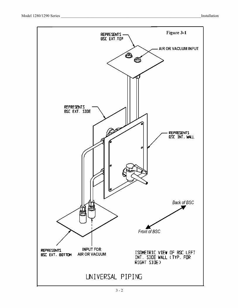
a. Universal Plumbing Option
The Universal Plumbing option is factory installed.External connection (1/4” NPT) to the unit is available on thetop and the underside of the cabinet, as well as the standardside connection. See Figure 3-1.
3.4 Exhaust Requirements
Filtered air from the cabinet may be exhausted directly intothe room or vented to the outside through an external exhaustsystem. Consult a biological safety officer or other qualifiedindividual for cabinet-type exhaust requirements. Refer to NSFStandard, NSF 49-2002, Annex E.
a. Direct Room Exhaust
A cardboard cover plate is shipped under the exhaust filterguard. It must be removed before the unit is placed into service.Locate the exhaust filter guard on the top of the cabinet.Remove the guard and discard the cardboard. Secure theexhaust filter guard as previously.
b. External Exhaust System (For Class II Type B3 Only)
If an external exhaust system is needed, use a canopy(thimble) connection (Figure 3-2). When the cabinet is certi-fied, check the opening in the canopy to ensure inward airflow,using a smoke stick. Verify that the building exhaust system issized to exhaust 30% more air than the cabinet exhausts.Models 1284, 1285 and 1288 exhaust an air volume of 356-390CFM. Models 1286, 1287, 1290 and 1291 exhaust an air vol-ume of 530-581 CFM. This helps to ensure proper air balanceat the front access opening for adequate containment.
IMPORTANT! The exhaust air must be drawn from the cabi-net through a dedicated exhaust system (only one BSC perexhaust system). The exhaust system may be connected to thecollar (optional exhaust transition) located on the top of theunit.
The exhaust system should have safeguardsagainst exhaust failure. It is required that a bio-logical safety officer, industrial hygienist or otherqualified individual review the agents and chemi-cals used inside the cabinet to determine if addi-tional filtration treatment is necessary before vent-ing to the atmosphere.
Model 1280/1290 Series _________________________________________________________________________Installation
Model 1280/1290 Series ________________________________________________________________________Installation
3 - 2

Model 1280/1290 Series ________________________________________________________________________Installation
3 - 3
Figure 3-2

3.5 Remote Alarm Contacts (Models 1288, 1290 and1291)
This area contains hazardous voltages. The pro-cedure should be done by qualified personnelonly.
For facilities requiring remote alarms connected to bio-logical safety cabinets, a relay with normally open and normal-ly closed contacts is installed in the blower electrical circuit.The alarm contacts are pre-wired as shown in Figure 3-3 and onthe Model 1288, 1290 and 1291 electrical schematics at theback of this manual. See Figure 3-3 for the remote alarm con-tact relay location.
The relay wires are identified N.O., N.C., and COM andare fitted with quick-connect terminals with the connectormates installed. The connectors need only to be pulled apart,the alarm wiring crimped onto the connectors and the twohalves pushed back together. The alarm wiring within theenclosure must be 18 to 22 gauge jacketed cable, rated for aminimum of 300V. The wires exit the control section of thecabinet through a hole identified by the large black arrow in theillustration below.
Model 1280/1290 Series ________________________________________________________________________Installation
3 - 4
Figure 3-3

Section 4 – Operation
4.1 Control and Indicating Devices (Refer to Figures 4-1, 4-2, and 4-3)
Before operating the cabinet, become familiar with the fol-lowing items:Blower Switch- The blower switch controls power to the inter-nal blower.Light Switch- The “Lights” switch controls power to the fluo-rescent lamp or the optional ultraviolet lamp. Both lamps arelocated in the work area.Ultra-Violet Light (Optional) - Recommended usage is onlywhen the laboratory is not in use.
Caution! Eyes or skin should not be exposedto ultra-violet light.
On cabinets equipped with the optional ultra-violet germicidallight, the dual purpose “Lights” switch provides the followingsettings: “Off” = center“On” top = fluorescent lamp“On” bottom = ultra-violet lamp
Either the fluorescent lamp or the ultra-violet lamp may be litat one time.
Model 1280/1290 Series _________________________________________________________________________Operation
4 - 1
Exhaust HEPA filter 18 x 24 x 6“ ” ”
Blower housing with direct drive motor
Supply HEPA filter 18 x 48 x 6“ ” ”
Fluorescent light canopy
Front air intake grille
Work surface Extra valve ports, one on each side
Removable rear paper catchStandard outlets,
one on each side
Standard key cocks, one on each side
Side View
Sliding window w/safety glass
Exhaust filter grille
External Damper Control
Removable side paper catch, one on each sideDrain valve
Series 1284 Class II A/B3 Biological Safety Cabinet
Removable vortex channel
Dwyer, 0“ - 2”mini-helic gauge
Front View
Air diffuser screen
Figure 4-14 ft. Series, Models 1284, 1285, and 1288

Alarm By-pass Switch - The Alarm By-pass switch silencesthe audible “Window Above 10 Inch” alarm for five minutes.The red visual indicator remains illuminated. The alarm rings-back to remind the operator that the window is still open morethan 10 inches. Static Pressure Gauge (In. W.G.) - The static pressure gaugemeasures the air pressure differential across the filters providingan indication of filter “loading”. As the filters become loaded,resistance increases and the reading on the static pressure gaugeincreases accordingly. When the reading increases by 50% fromoriginal measurement, cabinet airflow should be checked with athermoanemometer. Replace the filters if proper airflow cannotbe obtained.
The static pressure gauge should not be used as a directmeasure of airflow.
Blower Speed Control - The blower speed control is accessedfrom the rear of the control panel by removing the screw on thebottom of the control panel and swinging the control panel dooropen. The blower speed is adjusted by turning the screw on thevariable resistor mounted on the circuit board adjacent to thecontroller. (Refer to Figure 4-4) Turning the screw clockwiseincreases air velocity; counterclockwise decreases it.
The blower speed is factory-set and should only be changedby a qualified technician.
Model 1280/1290 Series __________________________________________________________________________Operation
4 - 2
Series 1286 Class II A/B3 Biological Safety Cabinet
Sliding window w/ safety glass
Exhaust filter grille
External Damper Control
Dwyer, 0“ - 2”mini-helic gauge
Removable side paper catch, one on each sideDrain valve
Removable vortex channel
Front View
Exhaust HEPA filter 24 x 24 x 6“ ” ”
Blower housing with direct drive motor
Supply HEPA filter 18 x 72 x 6“ ” ”Fluorescent
light canopy Air diffuser screen
Extra valve ports, one on each side
Removable rear paper catch
Standard outlets,one on each side
Front air intake grille
Work surfaceStandard key cocks, one on each side
Side View
Figure 4-2 6 ft. Series, Models 1286, 1287, 1290, 1291
Blower
On On
OffU.V.
ReceptaclesWindow
above 10 in.
On
Blower Alarm Bypass
Figure 4-3

Live voltage is present on the control terminals ofthe switches and dials on the front of the blowerpanel. Avoid touching these controls when reach-ing into the control panel and making any adjust-ments.
Measuring Blower Motor Voltage - Both blower motor volt-age and line voltage are measured at the three terminal connec-tors at the top of the circuit board. Refer to Figure 4-5.Blower Motor/Lights Reset Button (15 Amp) - The Reset but-ton (located on the left side of the control panel, directly abovethe Receptacle fuses) is an in-line circuit breaker for the inter-nal blower motor and lighting. If an overload occurs, the circuitbreaker will trip and the button will protrude from the panel.Depress the button to reset the circuit breaker.
Note: • Turn power off to the blower.• Turn power off to the lighting.• Press the blower motor/lighting Reset button.
Receptacle Fuses (7 Amp - Models 1284/1285/1288, 3 Amp -Models 1286/1287/1290/1291) - The receptacle fuses (2), locat-ed directly below the blower motor/lights Reset button, are forthe receptacles only. If an overload occurs, the fuses will openand require replacement.
Note: • Turn the power off.• Unplug the unit.• Replace the fuses -
P/N 230182, 7 Amp, ¼” x 1¼”P/N 230166, 3 Amp, ¼” x 1¼”
(Two spare fuses are located in a bracket on the inside of the control panel.)
Receptacles - Receptacles (115 Volts) are located on the leftand right sidewall of the workstation. Power is controlled bythe receptacle switch located on the control panel. The maxi-mum load is 5 amps total for Models 1284, 1285 and 1288.Models 1286, 1287, 1290 and 1291 have a maximum load of 2amps total. Models 1285 and 1287 are equipped with 2 singleEuropean 230V receptacles. Drain Valve - The drain valve, located on the right front side ofthe cabinet, is provided for the safe drainage of the drain pan.This valve must remain closed while work is being performedin the cabinet and be used only in the event of a major spill.
If a spill occurs, immediately consult a biologicalsafety officer or other qualified individual forproper procedures. To contain a spill, connect asealed hose from the drain valve to a sealed con-tainer.
Service Valves - Two service valves are standard with eachcabinet. These valves are located on the right and left side ofthe workstation and can be coded with the type of service thatthey supply. Identification index buttons are supplied.The cabinet supports four service valves. Additional valves maybe purchased from Thermo Forma.Exhaust Filter Guard - The exhaust filter guard, located ontop of the exhaust filter, protects the exhaust airflow and pre-vents the storage of objects on top of the housing.Sliding Window Assembly - The sliding window assemblyallows the operator to raise the glass window to place itemswithin the work area. If the sliding window is above the 10-inch level, a red light and audible alarm warns that an unsafecondition exists.
When work is being performed in the cabinet, thesliding window must be at the 10-inch position toavoid contamination to product and personnel.
Model 1280/1290 Series __________________________________________________________________________Operation
4 - 3
115VACLine Voltage
Neutral Voltage toBlower Motor
Figure 4-4
Figure 4-5

Model 1280/1290 Series ____________________________________________________________________Cabinet Start-Up
6 - 1
Section 5 - General Cautions
5.1 Caution Notes
• Following initial installation, the unit must be thoroughlytested and certified.
• All activities to be performed within the cabinet should beapproved by a biological safety officer or other qualifiedindividual.
• Since the HEPA filters remove particulates only (not gas),explosive/flammable substances should never be used inthe cabinet, unless approved and monitored by a biologicalsafety officer or other qualified individual.
• Ultra-violet lighting should not be used while personnel areusing the cabinet. If exposure cannot be avoided, the prop-er safety gear/clothing must be worn. Consult a biologicalsafety officer or other qualified individual for proper proce-dures.
• If the cabinet is to be used for biological or toxicologicalapplications, a biological safety officer or other qualifiedindividual must monitor it.
• If the unit needs to be serviced, it must be decontaminatedto protect service personnel from contamination. Afterservicing, the cabinet must be recertified by a qualified cer-tifying agency.
Do not use strong alkaline or caustic agents.Stainless steel is corrosion-resistant, not corro-sion-proof. Do not use solutions of sodiumhypochlorite (bleach) as they may also cause pit-ting and rusting.
• None of the perforations in the work area may be coveredor blocked, as airflow will be disrupted and contaminationmay occur.
• Paper catches should always be kept free of debris.
Section 6 - Cabinet Start-Up
6.1 General Recommendations
• Keep movement in the room to a minimum when the cabi-net is in use.
• Keep all laboratory doors closed to prevent drafts that maydisturb critical airflow.
• Pre-plan cabinet use and place everything needed in thecabinet so that nothing passes through the air barrier (in orout) during the procedure.
• Practice good aseptic technique to ensure safe use of thecabinet.
• If a spill occurs, clean it up immediately. Decontaminatethe work area and all affected equipment.
• Do not cover or block the exhaust grille.• Do not cover or block any perforations (air holes) in the
work area.
6.2 Use of Auxiliary Equipment in the Cabinet
Use auxiliary equipment in the cabinet only if proper pre-cautions are taken. Appliances used in the work area will causeturbulence, disturb the airflow and need to be carefully man-aged. The equipment should be placed at the rear of the work-space where it will have minimal effect.
A blender may be used in the cabinet. But because of theamount of aerosol it produces and the turbulence it causes, it isrecommended that it be removed from the cabinet as soon aspossible.
6.3 Cabinet Checklist
1. Verify that the Drain valve is closed (the handle turnedhorizontal).
2. Verify that all service valves are closed. 3. Verify that the cardboard exhaust filter protector has
been removed.
6.4 Start-Up Procedure
1. Turn the light on.2. Check the intake and exhaust grilles to ensure they are
not blocked.3. Turn the blower on.4. Place everything needed into the cabinet.5. Place the viewing window at 10 inches.

Model 1280/1290 Series ________________________________________________________________Routine Maintenance
8 - 1
Section 7 - Troubleshooting
7.1 Troubleshooting Guide
The following is a guide to troubleshooting the system. If acontaminated area of the cabinet must be entered to determineand/or resolve the source of a particular problem, the cabinetmust first be decontaminated.
Servicing of the unit must be performed by qual-ified service personnel.
Problem 1: Airflow in the cabinet work area and through theexhaust filter is inadequate.Possible causes:
• Exhaust filter is blocked by laboratory materials or the pro-tective shipping cover.
• If the biological safety cabinet is connected to an exhaustsystem, there may be inadequate exhaust suction or backpressure in the duct system. The system must be rebalancedto handle the correct air volume. A biological safety officershould be consulted.
• Low voltage is being applied to the blower motor.• Blower motor or speed control is defective.• Supply HEPA filter and Exhaust HEPA filter may be
loaded. Decontaminate the unit and replace both HEPA fil-ters.
Before any maintenance work is performed inthe biological safety cabinet, the unit must firstbe decontaminated.
Problem 2: Ultra violet light malfunctionPossible causes:
• Check lamp pins and socket ends for contact.• Starter is defective for the UV light.
Problem 3: Fluorescent light malfunctionPossible causes:
• Check lamp pins and socket ends for contact.• Lamp is defective.
Problem 4: Loud screeching noisePossible causes:
• Bearings are bad in the motor blower assembly.• Blower wheel is rubbing against the housing.
Section 8 - Routine Maintenance
8.1 Checking the Static Pressure Gauge “Zero”
Note: In order to provide an accurate reading, the indicatingneedle of the static pressure gauge should be precisely at zerowhen the cabinet is shut off. If the cabinet is connected to acentral exhaust system, the exhaust system must also be shutoff.
Following HEPA filter replacement, the static pressuregauge should be checked for zero when the cabinet is shut off.(refer to Section 8.2). When the cabinet is started up and properairflow balance has been reached, the reading on the gaugeshould be recorded. This initial reading will serve as a baselineindication of subsequent filter loading. When the readingincreases by approximately 50%, the airflow balance shouldagain be checked. Replacement of the filters may be required.
8.2 Zeroing the Static Pressure Gauge
1. Turn the cabinet off.2. Remove the front cover from the static pressure gauge
by grasping the front cover and turning it counterclock-wise.
3. Locate the Allen-type adjustment screw beside the gaugeneedle.
4. Turn the adjustment screw counterclockwise to lowerthe reading; clockwise to raise it.
8.3 Adjusting the Damper
Since the HEPA filter resistance may vary from filter to fil-ter (even filters of the same size), a damper has been installedin the cabinet exhaust system for maintaining proper airflowbalance. The purpose of the damper is to regulate the amount ofexhaust air, intake velocity and supply velocity. The damper hasbeen preset at the factory and should not be readjusted unlessthe proper velocities cannot be obtained.
Adjustments must be made by qualified personnelonly!

1. Layout test grids (refer to Section 8.4).2. Start-up the cabinet and allow it to run for at least twen-
ty minutes.3. Take airflow measurements. If airflow specifications are
not sufficient, open the control panel and check the volt-age on the power switch.
Note: Airflow measurements and voltages are recorded at thefactory with the cabinet connected to the appropriate AC powersupply.
4. Open the hinged control panel by removing the screw onthe bottom of the control panel and swinging the paneldoor open. Locate the blower motor circuit board.(Figure 4-4 & 4-5) Using a true RMS voltmeter, meas-ure and record the voltage drop across the white andblack wires leading to the terminal strip. (Figure 4-4)The blower speed control adjustment pot is located onthe upper left side of the board. Clockwise adjustment ofthis pot increases voltage supply to the blower motor,counterclockwise adjustment lowers the voltage supply.Adjust it 2-3 volts, up or down, depending upon the air-flow required. Retake the airflow measurements.
If it is determined that the damper must be adjusted inorder for the proper airflow balance to be maintained, adjust itas follows:
1. The damper control (Figure 8-1 below) is located on thetop of the cabinet.
2. Loosen the wingnut, move the lever to the desired posi-tion and retighten the wingnut.
Figure 8-1
Copies of the factory airflow test sheets are available inSection 15.
8.4 Biological Safety Cabinet Test Grids
a. 4-foot Series, Models 1284, 1285, and 1288
Model 1280/1290 Series ________________________________________________________________Routine Maintenance
8 - 2
OPEN I
½
¾
I
SHUT
5.25“
5.25“
4.00“
4.25“ 4.00“ 4.25“4.00“
4.00“
4.00“
Work access opening face area = 3.403 ft.sq.Open exhaust area* = 2.461 ft.sq. *Total area minus obstructed area
EXHAUST AIRFLOW GRID
TOTAL OF 12 AIRFLOWREADINGS
6.00“
5.50“
5.50“
6.00“1 2 3 4 6 7 85
6.00“5.29“
BACK ROW
DOWNFLOW GRID
FRONT ROW
CENTER ROW
6.00“

b. 6-foot Series, Models 1286, 1287, 1290, and 1291
A list of certification companies is included on theThermo Forma website, or call the Services department. SeePage iii.
Section 9 - Service
Service to the unit must be performed by qualifiedpersonnel. Recertify the cabinet after servicing.
Before service is to be performed on the cabinet,the unit must be decontaminated!
9.1 Replacing the Blower Motor (Models, 1284, 1285 and 1288, 4-foot)
a. Reversing the motor wiring (4 foot models only)
1. On the replacement motor: Disconnect the faston con-nectors securing the Orange wire to the Brown wire andYellow wire to the Purple wire.
2. Reconnect the Orange wire to the Purple wire and theYellow wire to the Brown wire.
b. Replacing the motor
1. Turn the unit off and disconnect it from the powersource.
2. Remove all dress panels.3. Remove the access panel.4. Unfasten the two latches connecting the blower to the
air plenum. 5. Remove the bolt toward the front of the cabinet that
connects the blower housing bracket to the top of thecabinet.
6. Remove the front screw on the right hand side of thecabinet that connects the blower housing bracket to theright hand wall of the cabinet.
7. Loosen - do not remove, the two remaining bolts thatconnect the blower housing bracket to the top of thecabinet.
8. Loosen - do not remove, the two remaining screws thatconnect the blower housing bracket to the right wall ofthe cabinet.
9. Slide the blower housing toward the rear of the cabinetas far as it will go.
10. Unbolt the removable inlet collar from the blower hous-ing.
Model 1280/1290 Series ___________________________________________________________________________Service
9 - 1
5.25“
5.25“
4.00“
5.25“ 4.00“ 4.00“ 5.25“4.00“
4.00“
4.00“
Work access opening face area = 5.052 ft.sq.Open exhaust area* = 3.368 ft.sq. *Total area minus obstructed area
EXHAUST AIRFLOW GRID
TOTAL OF 16 AIRFLOWREADINGS
6.00“
5.50“
5.50“
6.00“
1 2 3 4 6 7 8 9 10 11 125
6.00“5.55“
BACK ROW
DOWNFLOW GRID
FRONT ROW
CENTER ROW
6.00“

11. Unbolt the four-point motor mounting bracket from theblower housing.
12. Disconnect the motor wiring harness at the quick-con-nect plug.
13. Pull the motor, motor mounting bracket, removable inletcollar and blower wheel out of the blower housing.
14. Be sure to mark on the motor shaft the location of theblower wheel so that the new motor shaft can be linedup correctly with the required blower wheel position tofit properly inside the blower housing.
Note: After the motor is installed, but before replacing theplenum access panel, turn the motor on to ensure that rotation isin the clockwise direction (when viewed from the motor side ofthe blower).
9.2 Replacing the Blower Motor (Model 1286 Series6-foot)
1. Turn the unit off and disconnect it from the powersource.
2. Remove all dress panels.3. Remove the access panel.4. Unfasten the two latches connecting the blower to the
air plenum. 5. Remove the two bolts toward the front of the cabinet
that connect the blower housing brackets to the top ofthe cabinet.
6. Loosen - do not remove, the four remaining bolts thatconnect the blower housing brackets to the top of thecabinet.
7. Slide the blower housing toward the rear of the cabinetas far as it will go.
8. Disconnect the motor wiring harness at the quick-con-nect plug.
9. Unbolt the removable inlet collar from the blower hous-ing.
10. Pull the motor, motor mounting bracket, removable inletcollar, and blower wheel out of the blower housing.
11. Be sure to mark on the motor shaft the location of theblower wheel so that the new motor shaft can be linedup correctly with the required blower wheel position tofit properly inside the blower housing.
9.3 Replacing the Filters, All Models
Dispose of the old filters per established laborato-ry practices. If necessary, consult a bio-safetyofficer or other appropriate person.
1. Turn the unit off and disconnect it from the powersource.
2. Close the window.3. Remove the screw on the bottom left side, which secures
the control panel, and swing the panel open.4. Remove the eight screws securing the dress panel.
Remove the panel and set it aside.5. Remove the four hex nuts securing the lower cross brace
and set the brace to the side.6. Remove all hex nuts securing the pressure plate.7. Pry the pressure plate loose from the gasket and set it to
the side.8. Pull the Velcro boot loose from the exhaust filter
plenum.9. Release the two latches securing the supply plenum to
the blower housing.10. Disconnect the vinyl tubing that connects the Mag gauge
to the plenum.11. Remove the hex nuts (4 on the four-foot models, 6 on
the six-foot models), springs, washers and hold-downbrackets securing the plenum.
12. Remove the front filter hold-down studs (2 on the four-foot models, 3 on the six-foot models) in front of theplenum.
13. Slide the plenum from the cabinet.14. Remove the supply filter and clean the filter flange.15. Loosen - do not remove, the four bolts, springs and
washers that secure the exhaust filter.16. Slide the exhaust filter out, clean the filter flange and
install the new filter, ensuring that the gasket is on thetop.
17. Tighten the hex nuts to secure the new exhaust filter inposition.
18. Install the new supply filter with the gasket side down.19. Reinstall the supply plenum and assemble the compo-
nents in reverse order.The cabinet must be recertified after filter replacement.
Model 1280/1290 Series ___________________________________________________________________________Service
9 - 2

Assembly Notes:
• Latches connecting the plenum to the blower housing havea safety lock that must be released prior to opening thelatch.
• When tightening the filter hold-down nuts, the springsshould be compressed from 1/2 to 3/4 of their originalheight.
• Ensure that the vinyl tubing from the Mag gauge is recon-nected to the supply plenum.
• The Velcro connection on the exhaust boot must be smoothwith no gaps or loose spots to ensure proper sealing.
9.4 Replacing the Control Panel, All Models
Make certain power is disconnected from the unitprior to control panel removal.
Note: 2 people are required to perform this procedure.1. Remove (2) screws – a slotted screw located at the right
corner of the top surface of the control panel, and athumbscrew located at the left corner of the bottom sur-face of the panel. Swing the panel open.
2. Remove (2) #8-32 x 3/8” slotted screws that fasten thelight canopy cable retainer plate to the bottom side ofthe control panel mount. Disconnect the light canopyelectrical cable at the 9-position mate-n-lok connection.
3. Disassemble the sliding window switch mounting brack-et assembly from the unit, which is mounted to thelower channel (where the bottom of the control panelwas fastened), by removing the (2) #8-32 x 3/8” Phillipshead screws.
4. Disconnect the control panel electrical harness at the 15-position mate-n-lok connection located at the top rear ofthe panel.
5. Remove the tubing clamp and vinyl tubing from theupper end of the HEPA filter located inside the controlpanel. Pull the tubing out of the panel, making note ofits routing for reassembly.
6. With one person supporting the weight of the controlpanel, remove the (4) ¼-20 lockwasher hex nuts thatfasten the control panel assembly to the front surface ofthe cabinet.
7. Repeat the above steps in reverse order to reassemblethe control panel to the cabinet.
Model 1280/1290 Series _______________________________________________________________________Specifications
10 -1
Section 10 – Specifications
10.1 Models - 1284, 1285, and 1288 (4’ Cabinet withSliding Window)
Construction Work Surface: Type 304 Stainless Steel, #4 FinishCabinet: Cold Rolled Steel and Type 304 Stainless SteelFinish: Antique WhiteBaked Powder TCI Hybrid Paint
Dimensions Exterior: 54.0”W x 64.0”H x 32.5”F-BInterior: 49.0”W x 28.3”H x 22.25”F-B
Electrical Requirements1284 Main/Outlets (5): 115VAC, 1 Phase,
2 Wire, 60 Hz, 14 FLA(Total amps include 5A receptacle)Circuit Breaker: 20 AmpReceptacle - NEMA 5-20RExhaust System Volume Requirements: 356-390 CFM
1285 Main/Outlets (5): 230VAC, 1 Phase,2 Wire, 50 Hz, 11 FLA(Total amps include 5A receptacle)Circuit Breaker: 15 AmpReceptacle - EuropeanExhaust System Volume Requirements: 356-390 CFM
1288 Main/Outlets (5): 100VAC, 1 Phase,2 Wire, 50 Hz, 14 FLA(Total amps include 5A receptacle)Circuit Breaker: 20 AmpReceptacle - NEMA 5-20RExhaust System Volume Requirements: 356-390 CFM
Filters (1) Supply HEPA Filter (48”W x 18”F-B x 5-7/8”H)(1) Exhaust HEPA Filter (18”W x 24”F-B x 5-7/8”H)

1291 Main/Outlets (5): 100VAC, 1 Phase,2 Wire, 60 Hz, 16 FLA(Total amps include 2A receptacle)Circuit Breaker: 20 AmpsReceptacle - NEMA 5-15RExhaust System Volume Requirements: 530-581 CFM
Filters (1) Supply HEPA Filter (72”W x 18”F-B x 5-7/8”H)(1) Exhaust HEPA Filter (24”W x 24”F-B x 5-7/8”H)
Lights1286/1290/1291 (2) Fluorescent 85W,
(F72T12/N/HO)1287 (2) Fluorescent 85W,
(F72T12/CW/HO)(1) Optional UV 30W, (G30T8) Germicidal Lamp
Blower Motor 3/4 HP, 1500 RPM
Drain Pan Capacity 27.0 Gallons
Model 1280/1290 Series ______________________________________________________________________Specifications
10 -2
Lights (2) Fluorescent 60W, (F48T12/CWX/HO)(1) Optional UV 30W, (G30T8) Germicidal Lamp
Blower Motor 3/4 HP, 1625 RPM
Drain Pan Capacity 18.7 Gallons
10.2 Models - 1286, 1287, 1290 and 1291 (6’ Cabinetwith Sliding Window)
Construction Work Surface: Type 304 Stainless Steel, #4 FinishCabinet: Cold Rolled Steel and Type 304 Stainless SteelFinish: Antique White Baked-on Powder TCI Hybrid Paint
Dimensions Exterior: 78.0”W x 64.0”H x 32.5”F-BInterior: 73.0”W x 28.3”H x 22.25”F-B
Electrical Requirements1286 Main/ Outlets (5): 115VAC, 1 Phase,
2 Wire, 60 Hz, 15 FLA(Total amps include 2A receptacle)Circuit Breaker: 20 AmpsReceptacle - NEMA 5-15RExhaust System Volume Requirements: 530-581 CFM
1287 Main/Outlets (5): 230VAC, 1 Phase,2 Wire, 50 Hz, 8.5 FLA(Total amps include 2A receptacle)Circuit Breaker: 20 AmpsReceptacle - EuropeanExhaust System Volume Requirements: 530-581 CFM
1290 Main/Outlets (5): 100VAC, 1 Phase,2 Wire, 50 Hz, 13.5 FLA(Total amps include 2A receptacle)Circuit Breaker: 20 AmpsReceptacle - NEMA 5-15RExhaust System Volume Requirements: 530-581 CFM

10 -3
Model 1280/1290 Series ______________________________________________________________________________________________ Specifications

10 -4
Model 1280/1290 Series ______________________________________________________________________________________________ Specifications


Model 1280/1290 Series _________________________________________________________________________ Parts List
12 -1
Section 11 – Accessories
Description Order NumberService Valve 191275 Armrest, 4’ cabinet 191509 Armrest, 6’ cabinet 191512 Lab Chair with arms 191486 Lab Chair without arms 191487 Storage Cabinet, left side 191494 Storage Cabinet, right side 191495 UV Light, 30W 191419 UV Light, 30W portable 191070 IV Rod, stainless steel, 4’ cabinet 191571 IV Rod, stainless steel, 6’ cabinet 191572 Adjustable Foot Rest, 4’ cabinet 191127 ULPA Filter, 4 ft. cabinets, (1) exhaust & (1) supply*
760192 ULPA Filter, 6 ft. cabinets, (1) exhaust & (1) supply*
760193 Low Air Flow Alarm 191168 Exhaust Transition 191570 Hydraulic Stand, 4’ cabinet 191518 Hydraulic Stand, 6’ cabinet 191519 Adjustable Stand, 4’ cabinet 191550 Adjustable Stand, 6’ cabinet 191551 2-drawer storage cabinet, left side of stand 191524 Service Valve Kit, use w/ Universal Piping 191597 Universal Piping Kit* 191620 ADA Control Panel* 191496
*factory installed
Section 12 - Parts List
12.1 Model 1284
Stock # Description156106 3/4 HP Blower Motor (1625 RPM)170045 Capacitor, Motor 25MFD, 370V190396 Motor Speed Control 225250 Ballast (Fluorescent Lighting)141042 48” Fluorescent Lamp (60W, HO)230054 Circuit Breaker, 15A SP430304 Line cord Assembly, 20A, 120V,
Hospital Grade 760178 Filter, Supply HEPA 18” x 48” x
5-7/8” (Donaldson P/N P195042, Pressure Range: 0.78”-1.05” at 890 cfm) filter drop pressure tested per IES-RP-CC001.3 *See page 12.3
760179 Filter, Exhaust HEPA 18” x 24” x 5-7/8” (Donaldson P/N P194683, Pressure Range: 0.40”-0.65” at 360 cfm) filter drop pressure tested per IES-RP-CC001.3 *See page 12.3
500009 Ballast, (UV Lighting) 141014 30W Germicidal Lamp 280005 Pilot Light, #312, Red 300305 Delay Relay, (fixed 5 min.) 360095 Rocker Switch, SPST, Flat Black360096 Push-button Switch, SPDT360105 Rocker Switch, SPDT249025 Valve Body w/Tip 104008 Gauge, Static Pressure 360146 Rocker Switch, DPST230182 Fuses, 7 Amp, 1/4” x 1-1/4”
The parts for the Model 1285 are the same as those listedabove with the addition of the following:
Stock # Description 275012 Transformer, 1.5KVA, 240/120V460052 European Plug, 230V, 16A
The parts for the Model 1288 are the same as the Model1284 with the addition of:
Stock # Description 420098 Transformer, 12VA,
115V primary/12.6V secondary
The parts for the Model 1291 are the same as the Model1286 with the addition of:
Stock # Description 420098 Transformer, 12VA, 115V
primary/12.6V secondary 420057 Transformer, 175VA, dual
primary/dual secondary
*Filter Pressure Drop ConversionPressure drop across a HEPA filter is linear which allows
one to accurately predict the pressure drop at various CFM ifgiven a starting value. It is a straight proportion from one set-ting to the other.
Example: A filter rating of 0.31” of water at 352 CFM needs to be
converted to 530 CFM.
The formula is as follows:0.31 = x352 530
Solving for x (the needed pressure drop at 530 CFM) x=(0.31)*530
352
x=0.47” of water (rounded)
Model 1280/1290 Series __________________________________________________________________________Parts List
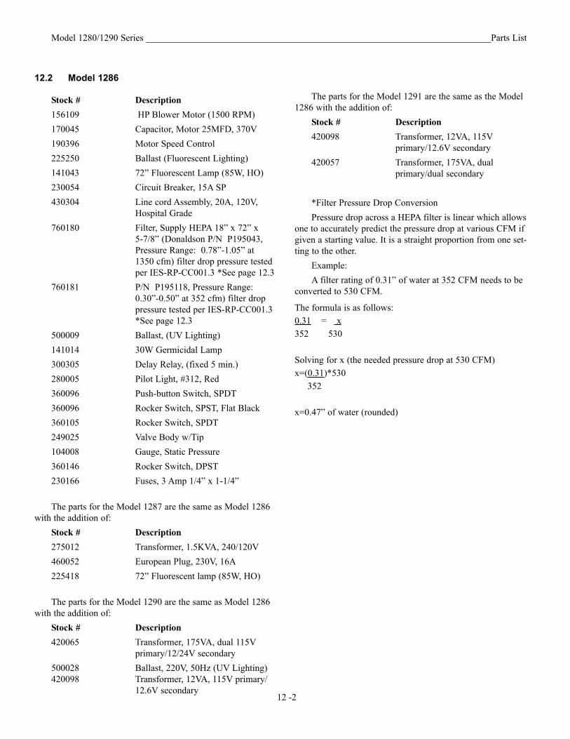
12.2 Model 1286
Stock # Description156109 HP Blower Motor (1500 RPM) 170045 Capacitor, Motor 25MFD, 370V190396 Motor Speed Control 225250 Ballast (Fluorescent Lighting)141043 72” Fluorescent Lamp (85W, HO) 230054 Circuit Breaker, 15A SP430304 Line cord Assembly, 20A, 120V,
Hospital Grade 760180 Filter, Supply HEPA 18” x 72” x
5-7/8” (Donaldson P/N P195043, Pressure Range: 0.78”-1.05” at 1350 cfm) filter drop pressure tested per IES-RP-CC001.3 *See page 12.3
760181 P/N P195118, Pressure Range: 0.30”-0.50” at 352 cfm) filter drop pressure tested per IES-RP-CC001.3*See page 12.3
500009 Ballast, (UV Lighting)141014 30W Germicidal Lamp 300305 Delay Relay, (fixed 5 min.)280005 Pilot Light, #312, Red 360096 Push-button Switch, SPDT360096 Rocker Switch, SPST, Flat Black360105 Rocker Switch, SPDT249025 Valve Body w/Tip 104008 Gauge, Static Pressure360146 Rocker Switch, DPST230166 Fuses, 3 Amp 1/4” x 1-1/4”
The parts for the Model 1287 are the same as Model 1286with the addition of:
Stock # Description 275012 Transformer, 1.5KVA, 240/120V460052 European Plug, 230V, 16A225418 72” Fluorescent lamp (85W, HO)
The parts for the Model 1290 are the same as Model 1286with the addition of:
Stock # Description 420065 Transformer, 175VA, dual 115V
primary/12/24V secondary 500028 Ballast, 220V, 50Hz (UV Lighting)420098 Transformer, 12VA, 115V primary/
12.6V secondary 12 -2

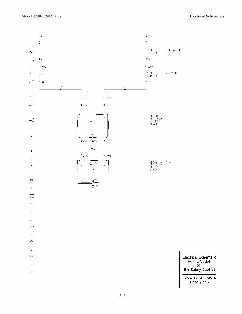
Model 1280/1290 Series ________________________________________________________________ Electrical Schematics
13 -1

Model 1280/1290 Series ________________________________________________________________ Electrical Schematics
13 -2

Model 1280/1290 Series ________________________________________________________________ Electrical Schematics
13 -3

Model 1280/1290 Series ________________________________________________________________ Electrical Schematics
13 -4

Model 1280/1290 Series ________________________________________________________________ Electrical Schematics
13 -5

Model 1280/1290 Series ________________________________________________________________ Electrical Schematics
13 -6
Model 1280/1290 Series ________________________________________________________________ Electrical Schematics
13 -7
Model 1280/1290 Series ________________________________________________________________ Electrical Schematics
13 -8

Model 1280/1290 Series ________________________________________________________________ Electrical Schematics
13 -9

Model 1280/1290 Series ________________________________________________________________ Electrical Schematics
13 -10

Model 1280/1290 Series ________________________________________________________________ Electrical Schematics
13 -11

Model 1280/1290 Series ________________________________________________________________ Electrical Schematics
13 -12

Model 1280/1290 Series ________________________________________________________________ Electrical Schematics
13 -13

Model 1280/1290 Series ________________________________________________________________ Electrical Schematics
13 -14

Model 1280/1290 Series ________________________________________________________________ Electrical Schematics
13 -15

Model 1280/1290 Series ________________________________________________________________ Electrical Schematics
13 -16

Model 1280/1290 Series ________________________________________________________________ Electrical Schematics
13 -17

Model 1280/1290 Series ________________________________________________________________ Electrical Schematics
13 -18

Model 1280/1290 Series ________________________________________________________________ Electrical Schematics
13 -19
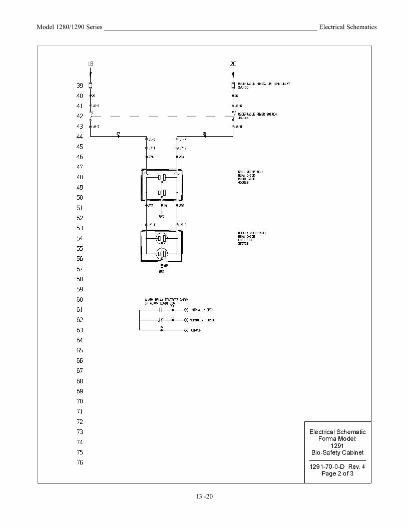
Model 1280/1290 Series ________________________________________________________________ Electrical Schematics
13 -20

Model 1280/1290 Series ________________________________________________________________ Electrical Schematics
13 -21

Model 1280/1290 Series ________________________________________________________________W
iring Diagram
s
13-22

Model 1280/1290 Series ___________________________________________________________________ W
iring Diagram
s
13 -23

THERMO FORMA LAMINAR FLOW EQUIPMENT WARRANTY USAThe Warranty Period starts two weeks from the date your equipment is shipped from our facility. This allows shipping time sothe warranty will go into effect at approximately the same time your equipment is delivered. The warranty protection extends toany subsequent owner.
During the first thirty-six (36) months, component parts proven to be defective in material or workmanship will be repaired orreplaced at Thermo Forma’s expense, including labor. Installation, calibration and certification is not covered by this warrantyagreement. The Thermo Forma Service Department must be contacted for warranty determination and direction prior to per-formance of any repairs. Expendable items, glass, filters and gaskets are excluded from this warranty.
Replacement or repair of component parts or equipment under this warranty shall not extend the warranty to either the equip-ment or to the component part beyond the original warranty period. The Thermo Forma Service Department must give priorapproval for return of any component or equipment. At Thermo Forma’s option, all defective parts must be returned to ThermoForma postage paid and replacement parts are shipped FOB destination.
THIS WARRANTY IS EXCLUSIVE AND IN LIEU OF ALL OTHER WARRANTIES, WHETHER WRITTEN, ORAL, OR IMPLIED.NO WARRANTIES OF MERCHANTABILITY OR FITNESS FOR A PARTICULAR PURPOSE SHALL APPLY. Thermo Formashall not be liable for any indirect or consequential damages including, without limitation, damages to lost profits or loss of prod-ucts.
Your local Thermo Forma Sales Office is ready to help with comprehensive site preparation information before your equipmentarrives. Printed instruction manuals carefully detail equipment installation, operation and preventive maintenance.
If equipment service is required, please call your Thermo Forma Service Office at 1-888-213-1790 (USA and Canada) or 1-740-373-4763. We’re ready to answer your questions on equipment warranty, operation, maintenance, service, and special applica-tions. Outside the USA, contract your local distributor for warranty information.
ISO9001REGISTERED
Rev. 2 1/17/01

THERMO FORMA LAMINAR FLOW EQUIPMENT WARRANTY INTERNATIONALThe Warranty Period starts two months from the date your equipment is shipped from our facility. This allows shipping timeso the warranty will go into effect at approximately the same time your equipment is delivered. The warranty protectionextends to any subsequent owner.
During the first thirty six (36) months, component parts proven to be defective in material or workmanship will be repaired orreplaced at Thermo Forma’s expense, excepting labor. Installation, calibration and certification is not covered by this warrantyagreement. The Thermo Forma Service Department must be contacted for warranty determination and direction prior to per-formance of any repairs. Expendable items, glass, filters and gaskets are excluded from this warranty.
Replacement or repair of component parts or equipment under this warranty shall not extend the warranty to either the equip-ment or to the component part beyond the original warranty period. The Thermo Forma Service Department must give priorapproval for return of any component or equipment. At Thermo Forma’s option, all defective parts must be returned toThermo Forma postage paid and replacement parts are shipped FOB destination.
THIS WARRANTY IS EXCLUSIVE AND IN LIEU OF ALL OTHER WARRANTIES, WHETHER WRITTEN, ORAL, ORIMPLIED. NO WARRANTIES OF MERCHANTABILITY OR FITNESS FOR A PARTICULAR PURPOSE SHALL APPLY.Thermo Forma shall not be liable for any indirect or consequential damages including, without limitation, damages to lostprofits or loss of products.
Your local Thermo Forma Sales Office is ready to help with comprehensive site preparation information before your equip-ment arrives. Printed instruction manuals carefully detail equipment installation, operation and preventive maintenance.
If equipment service is required, please call your Thermo Forma Service Office at 1-888-213-1790 (USA or Canada) or 1-740-373-4763. We’re ready to answer your questions on equipment warranty, operation, maintenance, service, and specialapplications. Outside the USA, contract your local distributor for warranty information.
ISO9001REGISTERED
Rev. 2 1/17/01

Locating a Certification Company Biological safety cabinet certification consists of a series of tests designed to verify that the cabinet is performing within operating parameters established by the manufacturer. To assure that a biological safety cabinet is operating as intended, each cabinet should be field-tested at the time of installation and at least annually thereafter. Cabinets should be re-certified whenever HEPA filters are changed, internal maintenance is performed, or is relocated. Three industry-related organizations maintain lists of companies and individuals who are active in the certification industry. You may contact these organizations at the addresses listed below. NSF International (NSF) and International Air Filtration Certifiers Association (IAFCA) sponsor certifier accreditation programs. Accredited certifiers have demonstrated proficiency at testing biological safety cabinets by successfully completing written and/or practical examinations. Biohazard Cabinet Field Certifier Program NSF International PO Box 130140 789 N. Dixboro Rd Ann Arbor, MI 48113-0140 Telephone (734) 769-8010 Or (800) NSF-MARK Fax (734) 769-0109 http://www.nsf.org/Certified/Biohazard-Certifier
IAFCA PO Box 12155 Columbus, OH 43212 Telephone (888) 679-1904 Fax (614) 486-1108 http://www.iafca.com/certifier.html
The Controlled Environment Testing Association (CETA) is a trade association devoted to promoting and developing quality assurance within the controlled environment testing industry. A list of active members is available by contacting the organization. Controlled Environment Testing Association 1500 Sunday Drive Suite 102 Raleigh, NC 27607 Telephone (919) 787-5181 Fax (919) 787-4916 http://www.cetainternational.org/members/corp_indiv.htm For your convenience we have included a partial list of agencies that perform certification on our website. If you do not find someone listed in your area, please contact Thermo Forma’s technical services department for additional references.

Millcreek Road, P.O. Box 649Marietta, Ohio 45750
U.S.A.
Telephone (740) 373-4763Telefax (740) 373-4189