modelling of wave energy conversion - ulisboa · 2 1. introduction to wave energy conversion 1.1....
TRANSCRIPT
1
Modelling of Wave Energy
Conversion
by
António F. O. Falcão Instituto Superior Técnico, Universidade Técnica de Lisboa
2014

2
1. Introduction to wave energy conversion
1.1. Introduction
1.1.1. The early years
The energy from ocean waves is the most conspicuous form of ocean energy,
possibly because of the, often spectacular, wave destructive effects. The waves are
produced by wind action and are therefore an indirect form of solar energy.
The possibility of converting wave energy into usable energy has inspired numerous
inventors: more than one thousand patents had been registered by 1980 [1.1] and the
number has increased markedly since then. The earliest such patent was filed in France
in 1799 by a father and a son named Girard [1.2].
Several reviews on wave energy conversion have been published in book form, as
conference and journal papers, and as reports. One should mention first the pioneering
book by McCormick [1.1] published in 1981 (reprinted in 2007), and also the books by
Shaw [1.3], Charlier and Justus [1.4] (their long chapter on wave energy was probably
completed by 1986), Ross [1.2] (written from a non-technical point of view by a
freelance journalist), Brooke [1.5] and Cruz [1.6]. A report prepared in 1999 for the UK
Department of Energy [1.7] and the final report [1.8] from the European Thematic
Network on Wave Energy (a project sponsored by the European Commission) provide
abundant information on the state-of-the-art at the time. Shorter reviews can be found in
[1.9-1.15]. An overview about the current status of wave energy conversion can be
found in [1.16]. This chapter is to a large extent an updated and more extensively
illustrated version of some parts of [1.14].
Fig. 1.1. Commander Yoshio Masuda (right) with Dr A.W. Lewis, in 2001 (courtesy of
A.W. Lewis, University College Cork).
Yoshio Masuda (1925-2009) (Fig. 1.1), a former Japanese navy officer, may be
regarded as the father of modern wave energy technology, with studies in Japan since

3
the 1940s. He developed a navigation buoy powered by wave energy, equipped with an
air turbine (Fig. 1.2), which was in fact what was later named as a (floating) oscillating
water column (OWC). These buoys were commercialized in Japan since 1965 (and later
in USA) [1.17,1.18]. Later, in Japan, Masuda promoted the construction, in 1976, of a
much larger device: a barge m)12m80( , named Kaimei (Fig. 1.3), used as a floating
testing platform housing several OWCs equipped with different types of air turbines
[1.19]. Probably because this was done at an early stage when the science and the
technology of wave energy conversion were in their infancy, the power output levels
achieved in the Kaimei testing program were not a great success.
Fig. 1.2. Outline of Japanese navigation buoy equipped with air turbine (based on
[1.18]).
Fig. 1.3. Japanese wave energy converter Kaimei.
The oil crisis of 1973 induced a major change in the renewable energies scenario
and raised the interest in large-scale energy production from the waves. A paper
published in 1974 in the prestigious journal Nature by Stephen Salter [1.20], of the
University of Edinburgh, became a landmark and brought wave energy to the attention
of the international scientific community. The British Government started in 1975 an
important research and development program in wave energy (Fig. 1.4) [1.21], followed
shortly afterwards by the Norwegian Government. The first conferences devoted to
wave energy took place in England (Canterbury, 1976, and Heathrow, 1978). This was
followed in 1979 by two more genuinely international conferences: Power from Sea
Waves (Edinburgh, June) and the First Symposium on Wave Energy Utilization

4
(Gothenburg, October-November). The Second International Symposium on Wave
Energy Utilization (Trondheim, Norway, 1982) coincided with a marked decline in
Government funding of the British wave energy program.
Fig. 1.4. Some of the devices whose development was funded by the British wave
energy program 1975-82. Clockwise, from top left: the Cockrell raft, the Salter duck,
the Bristol cylinder and the NEL oscillating water column [1.21].
Fig. 1.5. Shoreline prototypes installed in 1985 in Toftestallen, Norway: 500 kW
5
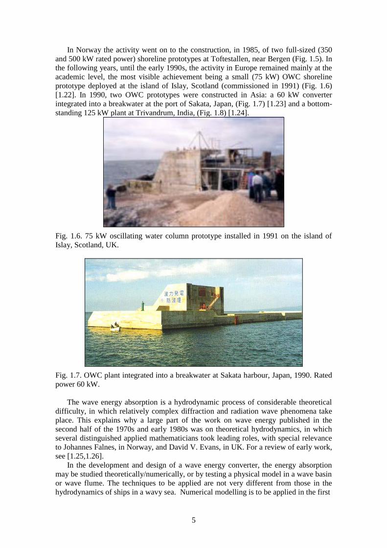
In Norway the activity went on to the construction, in 1985, of two full-sized (350
and 500 kW rated power) shoreline prototypes at Toftestallen, near Bergen (Fig. 1.5). In
the following years, until the early 1990s, the activity in Europe remained mainly at the
academic level, the most visible achievement being a small (75 kW) OWC shoreline
prototype deployed at the island of Islay, Scotland (commissioned in 1991) (Fig. 1.6)
[1.22]. In 1990, two OWC prototypes were constructed in Asia: a 60 kW converter
integrated into a breakwater at the port of Sakata, Japan, (Fig. 1.7) [1.23] and a bottom-
standing 125 kW plant at Trivandrum, India, (Fig. 1.8) [1.24].
Fig. 1.6. 75 kW oscillating water column prototype installed in 1991 on the island of
Islay, Scotland, UK.
Fig. 1.7. OWC plant integrated into a breakwater at Sakata harbour, Japan, 1990. Rated
power 60 kW.
The wave energy absorption is a hydrodynamic process of considerable theoretical
difficulty, in which relatively complex diffraction and radiation wave phenomena take
place. This explains why a large part of the work on wave energy published in the
second half of the 1970s and early 1980s was on theoretical hydrodynamics, in which
several distinguished applied mathematicians took leading roles, with special relevance
to Johannes Falnes, in Norway, and David V. Evans, in UK. For a review of early work,
see [1.25,1.26].
In the development and design of a wave energy converter, the energy absorption
may be studied theoretically/numerically, or by testing a physical model in a wave basin
or wave flume. The techniques to be applied are not very different from those in the
hydrodynamics of ships in a wavy sea. Numerical modelling is to be applied in the first

6
Fig. 1.8. Bottom-standing OWC installed in 1990 at Trivandrum, southern India. Rated
power 125 kW.
stages of the plant design. This is in most cases based on linear water wave theory, the
main limitations of which lie in its being unable to account for losses in water due to
real (viscous) fluid effects (large eddy, turbulence) and not being capable to model
accurately large amplitude water oscillations (nonlinear waves). Such effects are known
to be important (they also occur in naval engineering and in off-shore structures, where
more or less empirical corrections are currently applied). For these reasons, model tests
(scales 1:80 to 1:10) are carried out in wave basin when the final geometry of the plant
is already well established. Stephen Salter is widely regarded as the pioneer in model
testing of wave energy converters. In 1974 he started the experimental development of
the “duck” concept in a narrow wave flume at the University of Edinburgh [1.27] (Fig.
1.9).
Fig. 1.9. Early model testing of the duck wave energy converter in the wave flume of
the University of Edinburgh, 1974 [1.27]. Stephen Salter is on the right.
Salter’s experimental facilities were greatly improved with the construction, in 1977,
of the 10 m × 27.5 m × 1.2 m “wide tank” equipped with 89 independently driven
paddles, that made Edinburgh the leading centre for the experimental development in
wave energy conversion (for detailed information, including early photographs, see
[1.27]). Later, as the development of wave energy converter concepts progressed
towards the prototype construction stage, the need of larger-scale testing required the
use of very large laboratory facilities. This was the case, in Europe, of the large wave
tanks in Trondheim (Norway), Wageningen (Netherlands) and Nantes (France).

7
The utilization of wave energy involves a chain of energy conversion processes,
each of which is characterized by its efficiency as well as the constraints it introduces,
and has to be controlled. Particularly relevant is the hydrodynamic process of wave
energy absorption. The early theoretical studies on oscillating-body and OWC
converters revealed that, if the device is to be an efficient absorber, its own frequency of
oscillation should match the frequency of the incoming waves, i.e. it should operate at
near-resonance conditions. The ignorance of this rule underlies many failures by
inventors who regarded such systems as quasi-static (i.e. simply follow the wave
surface motion) rather than dynamic. In practice, the frequency-matching meets with
serious difficulties: (i) in most cases, except if the body (or the OWC) is quite large (this
meaning possibly sizes substantially larger than ten metres), its own frequency of
oscillation is too high as compared with typical ocean-wave frequencies; (ii) real waves
are not single-frequency. Acting on the power take-off system (PTO) to achieve
resonance has been named phase-control. Several phase-control strategies have been
proposed, including for devices in real irregular waves (for a review, see Falnes, [1.28]).
A control method that avoids the energy flow reversal was proposed by Budal and
Falnes [1.29] (see also [1.30]) and consists in latching the device in a fixed position
during certain intervals of the wave cycle so as to achieve approximate optimal phase
control. Apart from the pioneers Falnes and Budal, phase control (including latching)
was the object of theoretical studies from other researchers, namely Naito and
Nakamura [1.31], who established the relation between causality and optimum control
of wave energy converters, Nancy Nichols and her co-workers [1.32,1.33], who applied
the maximum principle of Pontryagin to numerically solve the problem, and Korde
[1.34] who studied the phase control of converters with several degrees of freedom.
Optimal phase control in real random waves and its practical implementation in wave
energy converters remain an open problem.
1.1.2. From the 1990s up to now
The situation in Europe was dramatically changed by the decision made in 1991 by
the European Commission of including wave energy in their R&D program on
renewable energies. The first projects started in 1992. Since then, more than thirty
projects on wave energy were funded by the European Commission involving a large
number of teams active in Europe. A few of these projects took the form of coordination
activities, namely one in 2000-2003 with 18 partners and, more recently (2004-2007),
the Coordination Action in Ocean Energy, with forty partners. Also sponsored (and in
some cases partly funded) by the European Commission were a series of European
Wave Energy Conferences (the more recent ones including also Tidal Energy):
Edinburgh, UK (1993), Lisbon, Portugal (1995), Patras, Greece (1998), Aalborg,
Denmark (2000), Cork, Ireland (2003), Glasgow, UK (2005), Porto, Portugal (2007),
Uppsala, Sweden (2009), Southampton, UK (2011), Aalborg, Denmark (2013). The
equally biennial International Conference on Ocean Energy, in which commercial,
economic and environmental issues were object of special attention, took place in
Bremerhaven, Germany (2006), Brest, France (2008), Bilbao, Spain (2010) and Dublin,
Ireland (2012). Sessions on ocean energy (with a major or dominant contribution of
papers on wave energy) are becoming increasingly frequent in annual conferences on
ocean engineering (namely the OMAE and ISOPE conferences) and on energy (the case
of the World Renewable Energy Congresses).
In 2001, the International Energy Agency established an Implementing Agreement
on Ocean Energy Systems (IEA-OES, presently with 19 countries as contracting

8
parties) whose mission is to facilitate and co-ordinate ocean energy research,
development and demonstration through international co-operation and information
exchange. Surveys of ongoing activities in wave energy worldwide can be found in the
IEA-OES annual reports.
In the last few years, growing interest in wave energy is taking place in northern
America (USA and Canada), involving the national and regional administrations,
research institutions and companies, and giving rise to frequent meetings and
conferences on ocean energy [1.35,1.36].
The main disadvantage of wave power, as with the wind from which is originates, is
its (largely random) variability in several time-scales: from wave to wave, with sea
state, and from month to month (although patterns of seasonal variation can be
recognized). The assessment of the wave energy resource is a basic prerequisite for the
strategic planning of its utilization and for the design of wave energy devices. The
characterization of the wave climate had been done before for other purposes, namely
navigation, and harbour, coastal and offshore engineering (where wave energy is
regarded as a nuisance), for which, however, the required information does not coincide
with what is needed in wave energy utilization planning and design. The studies aiming
at the characterization of the wave energy resource, having in view its utilization,
started naturally in those countries where the wave energy technology was developed
first. In Europe, this was notably the case of the United Kingdom [1.37,1.38]. When the
European Commission decided, in 1991, to start a series of two-year (1992-93)
Preliminary Actions in Wave Energy R&D, a project was included to review the
background on wave theory required for the exploitation of the resource and to produce
recommendations for its characterization [1.39]. The WERATLAS, a European Wave
Energy Atlas, also funded by the European Commission, was the follow-up of those
recommendations [1.40]. The WERATLAS remains the basic tool for wave energy
planning in Europe. Reviews on wave energy resource characterization can be found in
[1.41,1.42].
1.1.3. The technologies
Unlike large wind turbines, there is a wide variety of wave energy technologies,
resulting from the different ways in which energy can be absorbed from the waves, and
also depending on the water depth and on the location (shoreline, near-shore, offshore).
Recent reviews identified about one hundred projects at various stages of development.
The number does not seem to be decreasing: new concepts and technologies replace or
outnumber those that are being abandoned.
In general, the development, from concept to commercial stage, has been found to
be a difficult, slow and expensive process. Although substantial progress has been
achieved in the theoretical and numerical modelling of wave energy converters and of
their energy conversion chain, model testing in wave basin a time-consuming and
considerably expensive task is still essential. The final stage is testing under real sea
conditions. In almost every system, optimal wave energy absorption involves some kind
of resonance, which implies that the geometry and size of the structure are linked to
wavelength. For these reasons, if pilot plants are to be tested in the open ocean, they
must be large structures. For the same reasons, it is difficult, in the wave energy
technology, to follow what was done in the wind turbine industry (namely in Denmark):
relatively small machines where developed first, and were subsequently scaled up to
larger sizes and powers as the market developed. The high costs of constructing,
deploying, maintaining and testing large prototypes under sometimes very harsh
9
environmental conditions, has hindered the development of wave energy systems; in
most cases such operations were possible only with substantial financial support from
governments (or, in the European case, from the European Commission).
Several methods have been proposed to classify wave energy systems, according to
location, to working principle and to size (“point absorbers” versus “large” absorbers).
The classification in Fig. 1.10 is based mostly on working principle. The examples
shown are not intended to form an exhaustive list and were chosen among the projects
that reached the prototype stage or at least were object of extensive development effort.
The device categories shown in Fig. 1.10 are addressed hereafter.
Oscillating bodies (with hydraulic motor,
hydraulic turbine, linear
electrical generator)
Floating: Mighty Whale, Ocean Energy, Sperboy, Oceanlinx
Oscillating water
column (with air turbine)
Fixed structure
Isolated: Pico, LIMPET
In breakwater: Sakata, Mutriku
Overtopping (with low-head
hydraulic turbine) Floating structure (with concentration): Wave Dragon
Floating
Essentially translation (heave): AquaBuoy,
IPS Buoy, FO3, Wavebob, PowerBuoy
Essentially rotation: Pelamis, PS Frog, SEAREV
Submerged
Essentially translation (heave): AWS
Rotation (bottom-hinged): WaveRoller, Oyster
Fixed structure
Shoreline (with concentration): TAPCHAN
In breakwater (without concentration): SSG
Fig. 1.10. Various wave energy technologies.
1.2. The oscillating water column (OWC)
1.2.1. Fixed-structure OWC
Based on various energy-extracting methods, a wide variety of systems has been
proposed but only a few full-sized prototypes have been built and deployed in open
coastal waters. Most of these are or were located on the shoreline or near shore, and are
sometimes named first generation devices. In general these devices stand on the sea
bottom or are fixed to a rocky cliff. Shoreline devices have the advantage of easier
installation and maintenance, and do not require deep-water moorings and long
underwater electrical cables. The less energetic wave climate at the shoreline can be
partly compensated by natural wave energy concentration due to refraction and/or
diffraction (if the device is suitably located for that purpose). The typical first
generation device is the oscillating water column. Another example is the overtopping
device Tapchan (Tapered Channel Wave Power Device), a prototype of which was built
on the Norwegian coast in 1985 and operated for several years (see section 4 and Fig.
1.5).

10
The oscillating water column (OWC) device comprises a partly submerged concrete
or steel structure, open below the water surface, inside which air is trapped above the
water free surface (Fig. 1.11). The oscillating motion of the internal free surface
produced by the incident waves makes the air to flow through a turbine that drives an
electrical generator. The axial-flow Wells turbine was invented in 1976 by Alan
A.Wells (1924-2005) (at that time professor at Queen’s University, Belfast, UK) for
OWC applications [1.43] and has the advantage of not requiring rectifying valves (it is
self-rectifying). It has been used in most prototypes (Fig. 1.12). The most popular
alternative to the Wells turbine seems to be the self-rectifying impulse turbine, patented
by I.A. Babinsten in 1975 [1.44]. Its rotor is basically identical to the rotor of a
conventional single-stage steam turbine of axial-flow impulse type (the classical de
Laval steam turbine patented in 1889). Different versions of both self-rectifying
turbines have been developed and constructed [1.14,1.18,1.18a].
Fig. 1.11. Cross-sectional view of a bottom-standing OWC (Pico plant).
Fig. 1.12. Wells turbine with double row of guide vanes (400 kW Pico plant, Azores,
Portugal, 1999).
The OWC was one of the technologies whose development was funded by the
British wave energy program in the second half of the 1970s: the so-called NEL
(National Engineering Laboratory) oscillating water column device was made up of a
series of bottom-standing OWC chambers arranged as a terminator (its longest
dimension parallel to the wave crests during normal operation) (Fig. 1.4) [1.45].
Full sized OWC prototypes were built in Norway (in Toftestallen, near Bergen,
1985, Fig. 1.4 [1.46]), Japan (Sakata, 1990, Fig. 1.7 [1.23]), India (Vizhinjam, near
11
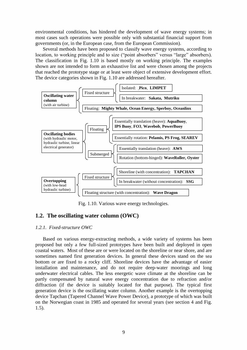
Trivandrum, Kerala state, 1990, Fig. 1.8 [1.24]), Portugal (Pico, Azores, 1999, Fig. 1.13
[1.47]), UK (the LIMPET plant in Islay island, Scotland, 2000, Fig. 1.14 [1.48]). The
largest
Fig. 1.13. Back view of the 400 kW OWC plant on the island of Pico, Azores, Portugal,
1999.
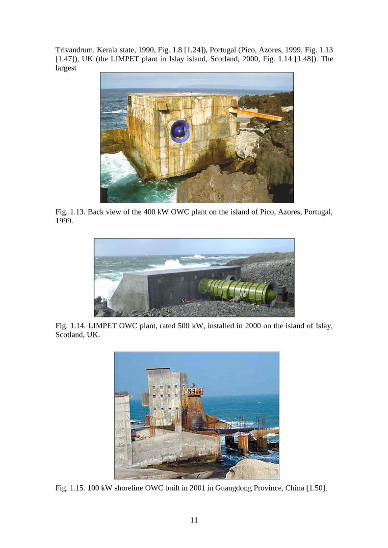
Fig. 1.14. LIMPET OWC plant, rated 500 kW, installed in 2000 on the island of Islay,
Scotland, UK.
Fig. 1.15. 100 kW shoreline OWC built in 2001 in Guangdong Province, China [1.50].

12
of all, a nearshore bottom-standing plant (named OSPREY) was destroyed by the sea
(in 1995) shortly after having been towed and sunk into place near the Scottish coast. In
all these cases, the structure is fixed (bottom-standing or built on rocky sloping wall)
and the main piece of equipment is the Wells air turbine driving an electrical generator.
Except for the OSPREY, the structure was made of concrete. The cross-sectional area of
these OWCs (at mid water-free-surface level) lies in the range 80-250 m2. Their
installed power capacity is (or was) in the range 60-500 kW (2 MW for OSPREY). Less
powerful shoreline OWC prototypes (also equipped with Wells turbines) were built in
Islay, UK, in 1991, Fig. 1.6 (75 kW, [1.49]), and in Guangdong, China, in 2001, Fig.
1.15 (100 kW, [1.50]).
It has been found theoretically [1.51] and experimentally since the early 1980s that
the wave energy absorption process can be enhanced by extending the chamber
structure by protruding (natural or man-made) walls in the direction of the waves,
forming a harbour or a collector. This concept has been put into practice in most OWC
prototypes. The Australian company Energetech developed a technology using a large
parabolic-shaped collector (shaped like a Tapchan collector) for this purpose; a
nearshore prototype, Oceanlinx Mk 1, was tested at Port Kembla, Australia, in 2005
[1.52], (Fig. 1.16).
Fig. 1.16. Oceanlinx Mk1, a 500 kW nearshore bottom-standing steel-made OWC
converter installed at Port Kembla, Australia, in 2005.
The design and construction of the structure (apart from the air turbine) are the most
critical issues in OWC technology, and the most influential on the economics of energy
produced from the waves. In the present situation, the civil construction dominates the
cost of the OWC plant. The integration of the plant structure into a breakwater has
several advantages: the constructional costs are shared, and the access for construction,
operation and maintenance of the wave energy plant become much easier. This has been
done successfully for the first time in the harbour of Sakata, Japan, in 1990 (Fig. 1.7,
[1.23]), where one of the caissons making up the breakwater had a special shape to
accommodate the OWC and the mechanical and electrical equipment. The option of the
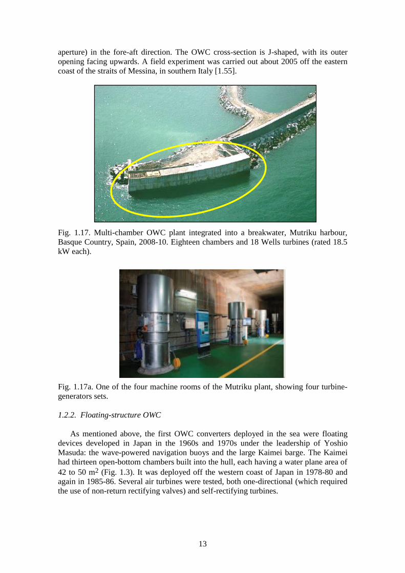
“breakwater OWC” was adopted in the breakwater constructed at the port of Mutriku, in
northern Spain (2008-10), with 16 chambers and 16 Wells turbines rated 18.5 kW each
(Figs 1.17,1.17a, [1.53]). A different geometry for an OWC embedded into a breakwater
was proposed by Boccotti [1.54], approaching a quasi-two-dimensional terminator
configuration, with an OWC that is long in the wave crest direction but narrow (small
13
aperture) in the fore-aft direction. The OWC cross-section is J-shaped, with its outer
opening facing upwards. A field experiment was carried out about 2005 off the eastern
coast of the straits of Messina, in southern Italy [1.55].
Fig. 1.17. Multi-chamber OWC plant integrated into a breakwater, Mutriku harbour,
Basque Country, Spain, 2008-10. Eighteen chambers and 18 Wells turbines (rated 18.5
kW each).
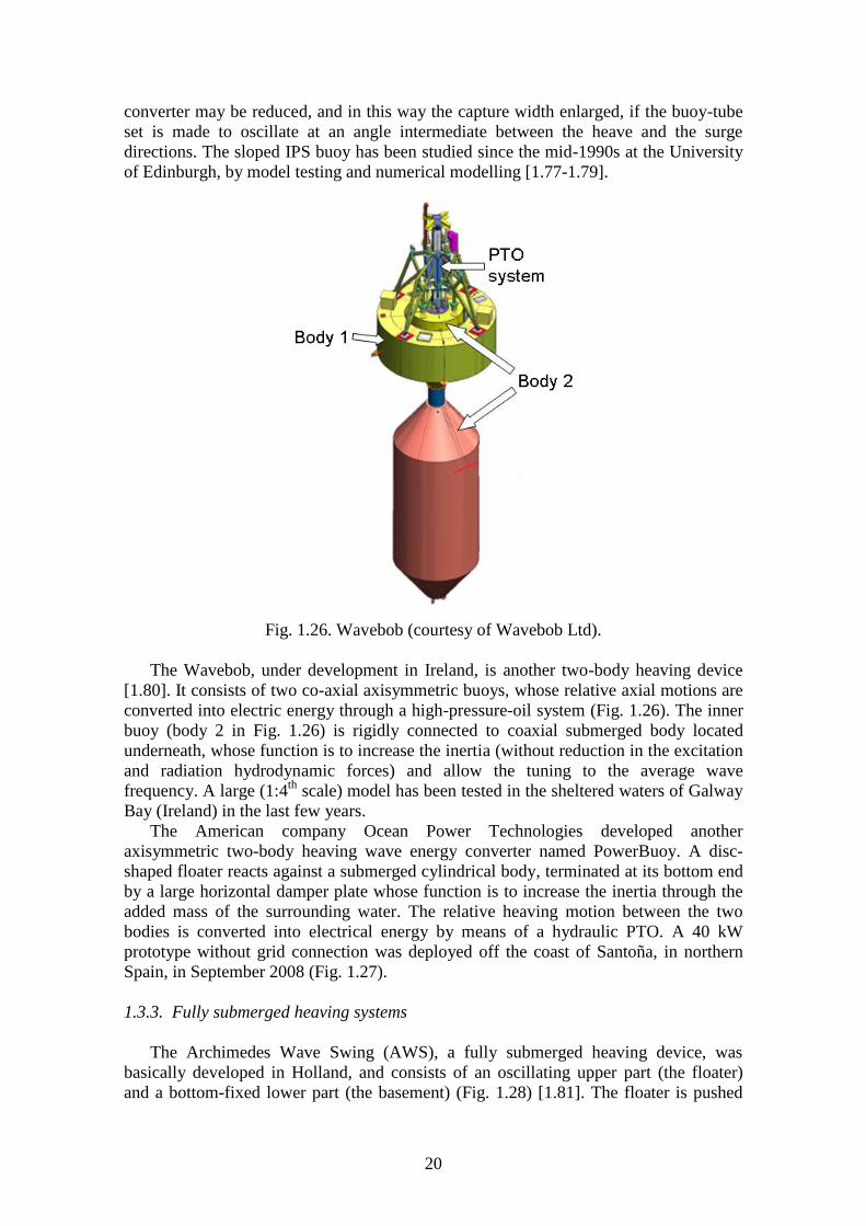
Fig. 1.17a. One of the four machine rooms of the Mutriku plant, showing four turbine-
generators sets.
1.2.2. Floating-structure OWC
As mentioned above, the first OWC converters deployed in the sea were floating
devices developed in Japan in the 1960s and 1970s under the leadership of Yoshio
Masuda: the wave-powered navigation buoys and the large Kaimei barge. The Kaimei
had thirteen open-bottom chambers built into the hull, each having a water plane area of
42 to 50 m2 (Fig. 1.3). It was deployed off the western coast of Japan in 1978-80 and
again in 1985-86. Several air turbines were tested, both one-directional (which required
the use of non-return rectifying valves) and self-rectifying turbines.

14
wavebuoyancy
air turbine
direction
wavebuoyancy
air turbine
direction
wavebuoyancy
air turbine
direction
Fig. 1.18. Schematic representation of the Backward Bent Duct Buoy (BBDB).
Masuda realized that the wave-to-pneumatic energy conversion of Kaimei was quite
unsatisfactory and conceived a different geometry for a floating OWC: the Backward
Bent Duct Buoy (BBDB). In the BBDB, the OWC duct is bent backward from the
incident wave direction (Fig.18) (which was found to be advantageous in comparison
with the frontward facing duct version) [1.56]. In this way, the length of the water
column could be made sufficiently large for resonance to be achieved, while keeping the
draught of the floating structure within acceptable limits. The BBDB converter was
studied (including model testing) in several countries (Japan, China, Denmark, Korea,
Ireland) and was used to power about one thousand navigation buoys in Japan and
China [1.50,1.57,1.58]. In the last few years, efforts have been underway in Ireland to
develop a large BBDB converter for deployment in the open ocean. A 1:4th-scale 12 m
long model equipped with a horizontal-axis Wells turbine (and later an impulse turbine)
has been tested in the sheltered sea waters of Galway Bay (western Ireland) since the
end of 2006 [1.59], Fig. 1.19.
Fig. 1.19. Backward Bent Duct Buoy (1:4th
of full scale) equipped with a Wells turbine
being tested in Galway Bay, Ireland, about 2008 (courtesy of OceanEnergy).
The Mighty Whale, another floating OWC converter, was developed by the Japan
Marine Science and Technology Center. After theoretical investigations and wave tank
testing, a full-sized prototype was designed and constructed. The device consists of a
floating structure (length 50 m, breadth 30 m, draught 12 m, displacement 4400 t) which
has three air chambers located at the front, side by side, and buoyancy tanks [1.60].
Each air chamber is connected to a Wells air turbine that drives an electric generator.

15
The total rated power is 110 kW. The device was deployed near the mouth of Gokasho
Bay, in Mie Prefecture, Japan, in 1998 (Fig. 1.20) and tested for several years.
Fig. 1.20. Mighty Whale, a three-chamber floating OWC equipped with Wells turbines,
deployed in 1998 in Gokasho Bay, Japan. Rated power 110 kW.
The Spar Buoy is possibly the simplest concept for a floating OWC. It is an
axisymmetric device (and so insensitive to wave direction) consisting basically of a
(relatively long) submerged vertical tail tube open at both ends, fixed to a floater that
moves essentially in heave. The length of the tube determines the resonance frequency
of the inner water column. The air flow displaced by the motion of the OWC relative to
the buoy drives an air turbine. Several types of wave-powered navigation buoys have
been based on this concept, which has also been considered for larger-scale energy
production. The spar buoy is possibly the first wave energy converter type to be object
of a detailed theoretical study [1.61,1.62]. A version of the Spar-buoy is being
developed at Instituto Superior Técnico, Lisbon: a 1:10th-scale model was tested in
2012 at NAREC, Northern England, Fig. 1.20a. The Sloped Buoy has some similarities
with the Spar Buoy and consists of a buoy with three sloped immersed tail tubes such
that the buoy-tube set is made to oscillate at an angle intermediate between the heave
and surge directions.
Fig. 1.20a. Model (1:10th-scale) of Spar-buoy tested in 2012 at NAREC, UK.
A report prepared for the British Department of Trade and Industry (DTI) compared
three types of floating OWCs for electricity generation in an Atlantic environment:
BBDB, Sloped Buoy and Spar Buoy [1.63].

16
The Australian company Oceanlinx deployed, in 2010, off Port Kembla, Australia, a
one-third scale grid-connected model of their most recent OWC device, the Mk3, which
(like the Kaimei three decades earlier) is a floating platform with several OWC
chambers (in this case eight chambers) each with an air turbine. During the tests only
two turbines (of different types) were installed (Fig. 1.21).
Fig. 1.21. One-third-scale Oceanlinx Mk3 multi-chamber floating OWC device. The
tests took place off Port Kembla, Australia, in 2010, with two grid-connected turbine-
generator sets of different types.
The structures of the floating OWC prototypes briefly described above are slack-
moored to the sea bed and so are largely free to oscillate (which may enhance the wave
energy absorption if the device is properly designed for that).
1.3. Oscillating body systems
Offshore devices (sometimes classified as third generation devices) are basically
oscillating bodies, either floating or (more rarely) fully submerged. They exploit the
more powerful wave regimes available in deep water (typically more than 40m water
depth). Oscillating bodies produce energy by reacting against the sea bottom (or a fixed
structure like a breakwater) or against another oscillating body. Offshore wave energy
converters are in general more complex compared with first generation systems. This,
together with additional problems associated with mooring, access for maintenance and
the need of long underwater electrical cables, has hindered their development, and only
recently some systems have reached, or come close to, the full-scale demonstration
stage.
1.3.1. Single-body heaving buoys
The simplest oscillating-body device is the heaving buoy reacting against a fixed
frame of reference (the sea bottom or a bottom-fixed structure). In most cases, such
systems are conceived as point absorbers (i.e. their horizontal dimensions are much
smaller than the wavelength).
An early attempt was a device named G-1T, consisting of a wedge-shaped buoy of
rectangular planform (1.8 m × 1.21 m at water line level and 1.2 m water draft) whose
vertical motion was guided by a steel structure fixed to a breakwater. The used PTO was
an early example of the hydraulic ram in a circuit including a hydraulic motor and a gas
accumulator. The tests, performed in Tokyo Bay in 1980, are reported in [1.64].
Another early example was the Norwegian buoy, consisting of a spherical floater
which could perform heaving oscillations relative to a strut connected to an anchor on
the sea bed through a universal joint [1.65]. The buoy could be phase-controlled by

17
latching and was equipped with an air turbine. A model (buoy diameter = 1 m), in
which the air turbine was simulated by an orifice, was tested (including latching
control) in the Trondheim Fjord in 1983 (Fig. 1.22).
Fig. 1.22. Norwegian heaving buoy in Trondheim Fjord, 1983 (courtesy of J. Falnes).
An alternative design is a buoy connected to a bottom-fixed structure by a cable
which is kept tight by a spring or similar device. The relative motion between the wave-
activated float on the sea surface and the seabed structure activates a PTO system. In the
device that was tested in Denmark in the early 1990s, the PTO (housed in a bottom-
fixed structure) consisted in a piston pump supplying high-pressure water to a hydraulic
turbine [1.66].
A version of the taut-moored buoy concept is being developed at Uppsala
University, Sweden, and uses a linear electrical generator (rather than a piston pump)
placed on the ocean floor [1.67]. A line from the top of the generator is connected to a
buoy located at the ocean surface, acting as power takeoff. Springs attached to the
translator of the generator store energy during half a wave cycle and simultaneously act
as a restoring force in the wave troughs (Fig. 1.23). Sea tests off the western coast of
Sweden of a 3 m diameter cylindrical buoy are reported in [1.67].
Another system with a heaving buoy driving a linear electrical generator was developed
at Oregon State University, USA [1.68]. It consists of a deep-draught spar and an
annular saucer-shaped buoy (Fig. 1.24). The spar is taut-moored to the sea bed by a
cable. The buoy is free to heave relative to the spar, but is constrained in all other
degrees of freedom by a linear bearing system. The forces imposed on the spar by the
relative velocity of the two bodies is converted into electricity by a permanent magnet
linear generator. The spar is designed to provide sufficient buoyancy to resist the
generator force in the down direction. A 10kW prototype L-10 (buoy outer radius 3.5 m,
spar length 6.7 m) was deployed off Newport, Oregon, in September 2008, and tested
[1.68].

18
Fig. 1.23. Swedish heaving buoy with linear electrical generator (courtesy of Uppsala
University).
Fig. 1.24. L-10 wave energy converter with linear electrical generator, developed at
Oregon State University.
1.3.2. Two-body heaving systems
The concept of a single floating body reacting against the sea floor may raise
difficulties due to the distance between the free surface and the bottom and/or to tidal
oscillations in sea level. Multi-body systems may be used instead, in which the energy

19
is converted from the relative motion between two bodies oscillating differently. The
hydrodynamics of two-body systems was theoretically analysed in detail by Falnes
[1.69]. Multi-body wave energy converters raise special control problems
[1.34,1.70,1.71].
The Bipartite Point Absorber concept [1.72] is an early example (1985) of a two-
point heaving system. It consists of two floaters, the outer one (with very low resonance
frequency) being a structure that acts as the reference and the inner one acting as the
resonating absorber. This device incorporates a concept that was later to be adopted in
the Wavebob (see below): the mass of the inner body is increased (without significantly
affecting the diffraction and radiation damping forces) by rigidly connecting it to a fully
submerged body located sufficiently far underneath.
Fig. 1.25. Schematic representation of the IPS buoy.
One of the most interesting two-body point absorbers for wave energy conversion is
the IPS buoy, invented by Sven A. Noren in 1978 [1.73] and initially developed in
Sweden by the company Interproject Service (IPS). This consists of a buoy rigidly
connected to a fully submerged vertical tube (the so-called acceleration tube) open at
both ends (Fig. 1.25). The tube contains a piston whose motion relative to the floater-
tube system (motion originated by wave action on the floater and by the inertia of the
water enclosed in the tube) drives a power take-off (PTO) mechanism. The same
inventor later (1981) introduced an improvement that significantly contributes to solve
the problem of the end-stops: the central part of the tube, along which the piston slides,
bells out at either end to limit the stroke of the piston [1.74]. A half-scale prototype of
the IPS buoy was tested in sea trials in Sweden, in the early 1980s [1.75]. The
AquaBuOY is a wave energy converter, developed in the 2000s, that combines the IPS
buoy concept with a pair of hose pumps to produce a flow of water at high pressure that
drives a Pelton turbine [1.79]. A prototype of the AquaBuOY was deployed and tested
in 2007 in the Pacific Ocean off the coast of Oregon. A variant of the initial IPS buoy
concept, due to Stephen Salter, is the sloped IPS buoy: the natural frequency of the
20
converter may be reduced, and in this way the capture width enlarged, if the buoy-tube
set is made to oscillate at an angle intermediate between the heave and the surge
directions. The sloped IPS buoy has been studied since the mid-1990s at the University
of Edinburgh, by model testing and numerical modelling [1.77-1.79].
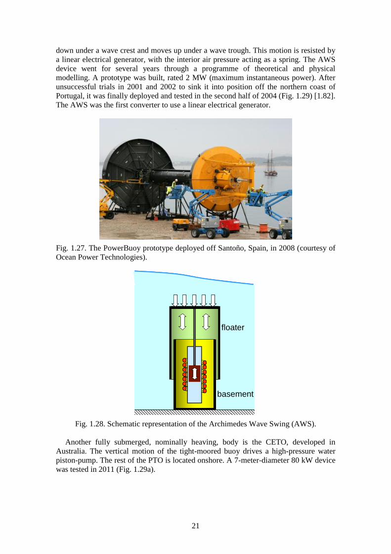
Fig. 1.26. Wavebob (courtesy of Wavebob Ltd).
The Wavebob, under development in Ireland, is another two-body heaving device
[1.80]. It consists of two co-axial axisymmetric buoys, whose relative axial motions are
converted into electric energy through a high-pressure-oil system (Fig. 1.26). The inner
buoy (body 2 in Fig. 1.26) is rigidly connected to coaxial submerged body located
underneath, whose function is to increase the inertia (without reduction in the excitation
and radiation hydrodynamic forces) and allow the tuning to the average wave
frequency. A large (1:4th
scale) model has been tested in the sheltered waters of Galway
Bay (Ireland) in the last few years.
The American company Ocean Power Technologies developed another
axisymmetric two-body heaving wave energy converter named PowerBuoy. A disc-
shaped floater reacts against a submerged cylindrical body, terminated at its bottom end
by a large horizontal damper plate whose function is to increase the inertia through the
added mass of the surrounding water. The relative heaving motion between the two
bodies is converted into electrical energy by means of a hydraulic PTO. A 40 kW
prototype without grid connection was deployed off the coast of Santoña, in northern
Spain, in September 2008 (Fig. 1.27).
1.3.3. Fully submerged heaving systems
The Archimedes Wave Swing (AWS), a fully submerged heaving device, was
basically developed in Holland, and consists of an oscillating upper part (the floater)
and a bottom-fixed lower part (the basement) (Fig. 1.28) [1.81]. The floater is pushed
21
down under a wave crest and moves up under a wave trough. This motion is resisted by
a linear electrical generator, with the interior air pressure acting as a spring. The AWS
device went for several years through a programme of theoretical and physical
modelling. A prototype was built, rated 2 MW (maximum instantaneous power). After
unsuccessful trials in 2001 and 2002 to sink it into position off the northern coast of
Portugal, it was finally deployed and tested in the second half of 2004 (Fig. 1.29) [1.82].
The AWS was the first converter to use a linear electrical generator.
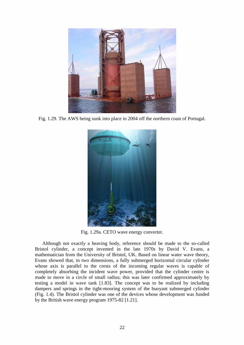
Fig. 1.27. The PowerBuoy prototype deployed off Santoño, Spain, in 2008 (courtesy of
Ocean Power Technologies).
floater
basement
floater
basement
Fig. 1.28. Schematic representation of the Archimedes Wave Swing (AWS).
Another fully submerged, nominally heaving, body is the CETO, developed in
Australia. The vertical motion of the tight-moored buoy drives a high-pressure water
piston-pump. The rest of the PTO is located onshore. A 7-meter-diameter 80 kW device
was tested in 2011 (Fig. 1.29a).
22
Fig. 1.29. The AWS being sunk into place in 2004 off the northern coast of Portugal.
Fig. 1.29a. CETO wave energy converter.
Although not exactly a heaving body, reference should be made to the so-called
Bristol cylinder, a concept invented in the late 1970s by David V. Evans, a
mathematician from the University of Bristol, UK. Based on linear water wave theory,
Evans showed that, in two dimensions, a fully submerged horizontal circular cylinder
whose axis is parallel to the crests of the incoming regular waves is capable of
completely absorbing the incident wave power, provided that the cylinder centre is
made to move in a circle of small radius; this was later confirmed approximately by
testing a model in wave tank [1.83]. The concept was to be realized by including
dampers and springs in the tight-mooring system of the buoyant submerged cylinder
(Fig. 1.4). The Bristol cylinder was one of the devices whose development was funded
by the British wave energy program 1975-82 [1.21].
23
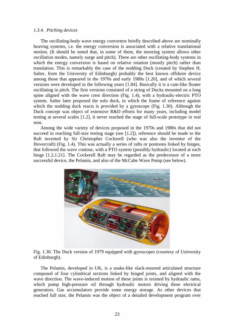
1.3.4. Pitching devices
The oscillating-body wave energy converters briefly described above are nominally
heaving systems, i.e. the energy conversion is associated with a relative translational
motion. (It should be noted that, in some of them, the mooring system allows other
oscillation modes, namely surge and pitch). There are other oscillating-body systems in
which the energy conversion is based on relative rotation (mostly pitch) rather than
translation. This is remarkably the case of the nodding Duck (created by Stephen H.
Salter, from the University of Edinburgh) probably the best known offshore device
among those that appeared in the 1970s and early 1980s [1.20], and of which several
versions were developed in the following years [1.84]. Basically it is a cam-like floater
oscillating in pitch. The first versions consisted of a string of Ducks mounted on a long
spine aligned with the wave crest direction (Fig. 1.4), with a hydraulic-electric PTO
system. Salter later proposed the solo duck, in which the frame of reference against
which the nodding duck reacts is provided by a gyroscope (Fig. 1.30). Although the
Duck concept was object of extensive R&D efforts for many years, including model
testing at several scales [1.2], it never reached the stage of full-scale prototype in real
seas.
Among the wide variety of devices proposed in the 1970s and 1980s that did not
succeed in reaching full-size testing stage (see [1.2]), reference should be made to the
Raft invented by Sir Christopher Cockerell (who was also the inventor of the
Hovercraft) (Fig. 1.4). This was actually a series of rafts or pontoons linked by hinges,
that followed the wave contour, with a PTO system (possibly hydraulic) located at each
hinge [1.2,1.21]. The Cockerell Raft may be regarded as the predecessor of a more
successful device, the Pelamis, and also of the McCabe Wave Pump (see below).
Fig. 1.30. The Duck version of 1979 equipped with gyroscopes (courtesy of University
of Edinburgh).
The Pelamis, developed in UK, is a snake-like slack-moored articulated structure
composed of four cylindrical sections linked by hinged joints, and aligned with the
wave direction. The wave-induced motion of these joints is resisted by hydraulic rams,
which pump high-pressure oil through hydraulic motors driving three electrical
generators. Gas accumulators provide some energy storage. As other devices that
reached full size, the Pelamis was the object of a detailed development program over

24
several years, that included theoretical/numerical modelling and physical model testing
at several scales [1.85,1.86]. Sea trials of a full-sized prototype (120 m long, 3.5 m
diameter, 750 kW rated power) took place in 2004 in Scotland. A set of three Pelamis
devices was deployed off the Portuguese northern coast in the second half of 2008 (Fig.
1.31), making it the first grid-connected wave farm worldwide.
Fig. 1.31. The three-unit 3 × 750 kW Pelamis wave farm in calm sea off northern
Portugal, 2008 (courtesy of R. Barros).
The McCabe Wave Pump has conceptual similarities to the Cockerell Raft and the
Pelamis: it consists of there rectangular steel pontoons hinged together, with the heaving
motion of the central pontoon damped by a submerged horizontal plate [1.87] (Fig.
1.32). Two sets of hydraulic rams and a hydraulic PTO convert the relative rotational
motions of the pontoon into useful energy. A 40 m long prototype was deployed in 1996
off the coast of Kilbaha, County Clare, Ireland.
Fig. 1.32. Side and plan views of the McCabe Wave Pump.
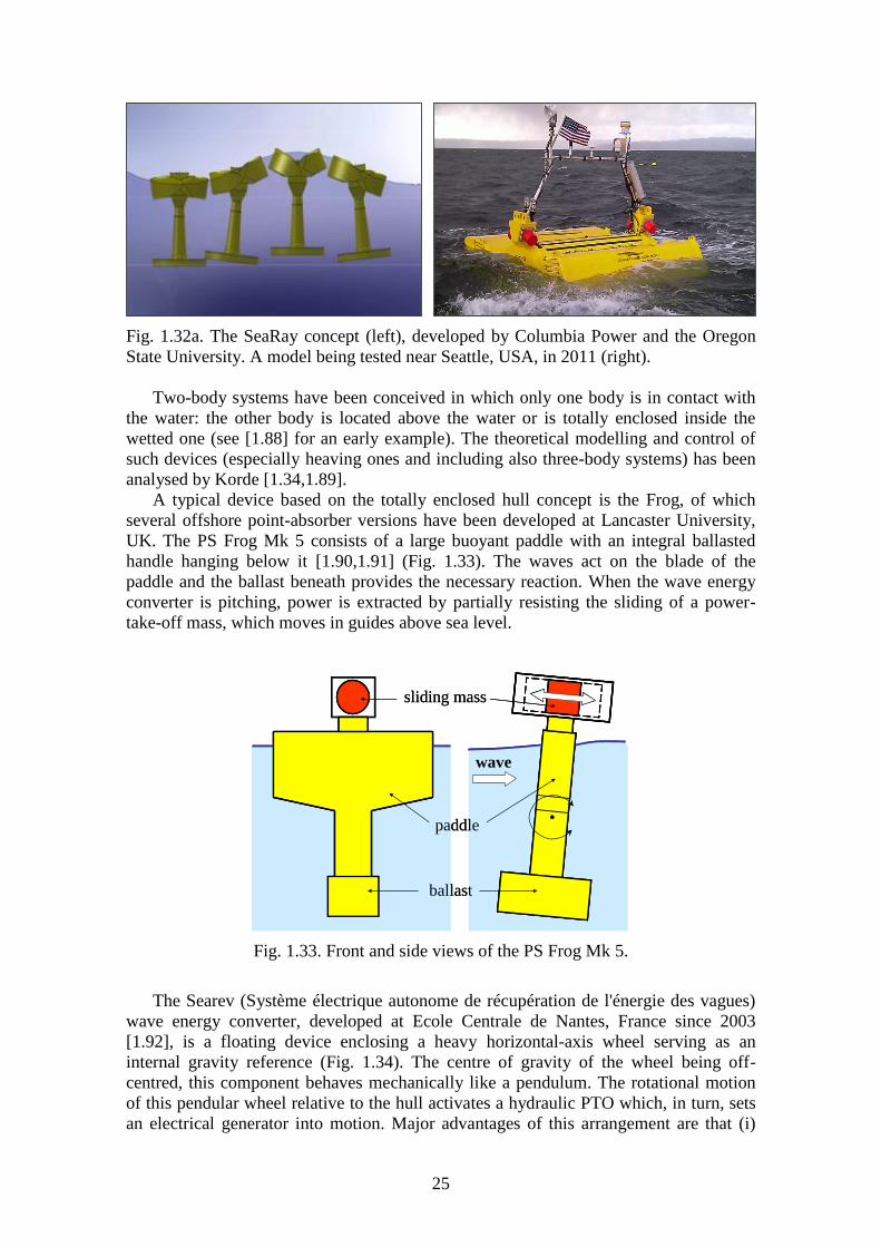
The SeaRay, developed in USA by Columbia Power and by Oregon State University,
is largely similar to the McCabe Wave Pump. It consists of two bodies that can oscillate
in pitch with respect to a centrally-positioned long cylindrical body whose inertia is
enlarged by a submerged plate. The relative motion is converted directly by an electrical
generator. Model testing took place in 2011 off Seattle (Fig. 1.32a).
25
Fig. 1.32a. The SeaRay concept (left), developed by Columbia Power and the Oregon
State University. A model being tested near Seattle, USA, in 2011 (right).
Two-body systems have been conceived in which only one body is in contact with
the water: the other body is located above the water or is totally enclosed inside the
wetted one (see [1.88] for an early example). The theoretical modelling and control of
such devices (especially heaving ones and including also three-body systems) has been
analysed by Korde [1.34,1.89].
A typical device based on the totally enclosed hull concept is the Frog, of which
several offshore point-absorber versions have been developed at Lancaster University,
UK. The PS Frog Mk 5 consists of a large buoyant paddle with an integral ballasted
handle hanging below it [1.90,1.91] (Fig. 1.33). The waves act on the blade of the
paddle and the ballast beneath provides the necessary reaction. When the wave energy
converter is pitching, power is extracted by partially resisting the sliding of a power-
take-off mass, which moves in guides above sea level.
sliding mass
wave
paddle
ballast
sliding mass
wave
paddle
ballast
Fig. 1.33. Front and side views of the PS Frog Mk 5.
The Searev (Système électrique autonome de récupération de l'énergie des vagues)
wave energy converter, developed at Ecole Centrale de Nantes, France since 2003
[1.92], is a floating device enclosing a heavy horizontal-axis wheel serving as an
internal gravity reference (Fig. 1.34). The centre of gravity of the wheel being off-
centred, this component behaves mechanically like a pendulum. The rotational motion
of this pendular wheel relative to the hull activates a hydraulic PTO which, in turn, sets
an electrical generator into motion. Major advantages of this arrangement are that (i)

26
(like the Frog) all the moving parts (mechanic, hydraulic, electrical components) are
sheltered from the action of the sea inside a closed hull, and (ii) the choice of a wheel
working as a pendulum involve neither end-stops nor any security system limiting the
stroke.
Buoy
Pendulum
Hydraulic
ramsBuoy
Pendulum
Hydraulic
rams
Fig. 1.34. Schematic representation of the Searev.
The Spanish company Oceantec developed another offshore floating energy
converter that extracts energy basically from the pitching motion. It has the shape of an
elongated horizontal cylinder with ellipsoidal ends whose major axis is aligned with the
incident wave direction [1.93]. The energy conversion process is based on the relative
inertial motion that the waves cause in a gyroscopic system [1.94]. This motion is used
to feed an electrical generator through a series of transformation stages. A 1:4th
scale
prototype (11.25 m long) was deployed off the coast of Guipúzcoa (northern Spain) in
September 2008 and was tested for several months (Fig. 1.35) [1.93].
Fig. 1.35. Oceantec device (1:4th
scale) deployed in 2008 off the northern coast of Spain
(courtesy of Oceantec). The pitching floater reacts against a gyroscopic system.

27
1.3.5. Overhanging and bottom-hinged systems
Single oscillating-body devices operating in pitching mode have been proposed,
based on the overhanging pendulum or on the inverted pendulum hinged at the sea bed
concept. The Pendulor device was developed in Japan since the early 1980s [1.95]. It
consists basically of a bottom-standing caisson open to the sea (Fig. 1.36). In regular
Fig. 1.36. The Pendulor device, installed in Muroran port, Hokkaido, Japan, in 1983
[1.95].
waves, if the caisson is properly sized, resonance is established by multiple reflections
at the back wall and at the opening. Energy is extracted from the wave system by the
swinging motion of a flat plate hanging as a pendulum from the top of the caisson,
spanning the caisson width and extending downwards close to the bottom. The plate
motion is converted into useful energy by a high-pressure-oil hydraulic circuit. A
onshore prototype, equipped with a 5 kW hydraulic motor, was installed in 1983 at
Muroran Port, on the south coast of Hokkaido, Japan, and was operated for several
years.
The mace, invented by Stephen Salter in the early 1990s [1.96], consists of a
buoyant spar, with symmetry about the vertical axis, that can swing, as an inverted
pendulum, about a universal joint at the sea bottom (Fig. 1.37). The power take-off
reaction to the sea bed is via a set of cables wound several times round a winch-drum
leading both fore and aft in the prevailing wave direction. The wave-activated
reciprocating rotation of the drum is converted into useful energy by means of a
hydraulic system. A basically similar concept of a bottom-pivoted vertical cylinder is
being developed in Australia [1.97].
Two devices, namely Oyster and WaveRoller, are presently under development that
share the same basic concept: a buoyant flap hinged at the sea bed, whose pitching
oscillations activate a set of double-acting hydraulic rams located on the sea bed that
pump high pressure fluid to shore via a sub-sea pipeline. The fluid flow is converted
into electrical energy by a conventional hydraulic circuit. These devices are intended for
deployment close to shore in relatively shallow water (10-15 m). Apart from size (the
Oyster is larger) and detailed design, there are some conceptual differences between
them. The Oyster (under development in UK) has a surface piercing flap that spans the
whole water depth and the fluid is sea water powering a Pelton turbine located onshore
[1.98], whereas the WaveRoller (a Finish device) is totally submerged and uses oil as
working fluid [1.99]. Several swinging flaps can feed a single onshore generator,
attached to a single manifold pipeline. A 3.5 m high, 4.5 m wide prototype of the
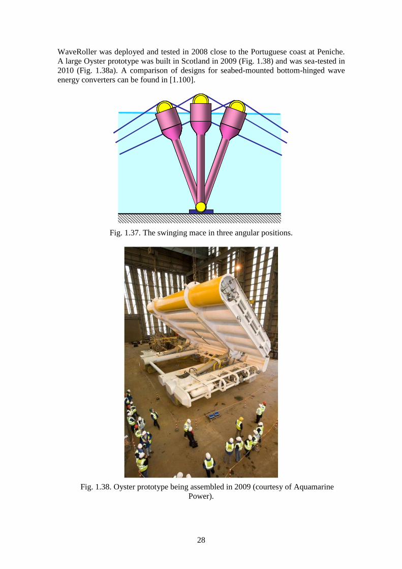
28
WaveRoller was deployed and tested in 2008 close to the Portuguese coast at Peniche.
A large Oyster prototype was built in Scotland in 2009 (Fig. 1.38) and was sea-tested in
2010 (Fig. 1.38a). A comparison of designs for seabed-mounted bottom-hinged wave
energy converters can be found in [1.100].
Fig. 1.37. The swinging mace in three angular positions.
Fig. 1.38. Oyster prototype being assembled in 2009 (courtesy of Aquamarine
Power).

29
Fig. 1.38a. A prototype of Oyster being tested at EMEC, Scotland, in 2010.
A three-flap 1003 kW prototype of the Waveroller was deployed in 2012 in 15 m
water depth, at Peniche, 100 km north of Lisbon (Fig. 1.38b).
Fig. 1.38b. The three-flap Waveroller prototype shortly before being sunk into place in
15 m water depth, off Peniche, 100 km north of Lisbon, in 2012.
1.3.6. Many-body systems
In some cases, the device consists of a large set of floating point absorbers reacting
against a common frame and sharing a common PTO. This is the case of FO3 [1.101]
(mostly a Norwegian project), a nearshore or offshore system consisting of an array of
21 axisymmetric buoys (or “eggs”) oscillating in heave with respect to a large floating
structure of square planform with very low resonance frequency and housing a
hydraulic PTO. Initially, a 1:20th
-scale model of the device was tested in Trondheim,
Norway in the early 2000s. This was followed by the construction of “Buldra”, a 1:3rd
-
scale research model (12 m × 12 m) that was tested in the mid-2000s close to the
southern Norwegian cost (Fig. 1.39).

30
Fig. 1.39. One-third-scale 12 m × 12 m model of multi-body device FO3 “Buldra” being
tested close to the southern coast of Norway, about 2004.
The Wave Star, developed in Denmark, consists of two rectilinear arrays of closely
spaced floaters located on both sides of a long bottom-standing steel structure that is
aligned with the dominant wave direction and houses a hydraulic PTO consisting of a
high-pressure-oil hydraulic circuit equipped with hydraulic motors. The waves make the
buoys to swing about their common reference frame and pump oil into the hydraulic
circuit. A 1:10th
-scale 24 m long 5.5 kW model with 10 buoys on each side was
deployed in 2006 in Nissum Bredning, Denmark, and tested with grid connection for a
couple of years [1.102] (Fig. 1.40). A larger, one-half-scale model (with two 5-meter-
diameter floaters rated 25 kW each) was tested in 2009 in 7-meter-deep water in the
North Sea off Hanstholm, Denmark (Fig. 1.41). The Brazilian hyperbaric device is
based on a similar concept, the main differences being that the reference frame about
which the buoys are made to swing is a vertical breakwater, and water is pumped to
feed a Pelton turbine in a circuit that includes an air accumulator. A 1:10th
-scale model
of the hyperbaric device was tested in 2006 in a large wave tank [1.103] (Fig. 1.42). A
two-unit prototype of this device was recently installed at a breakwater, at São Gonçalo do
Amarante, Ceará State, Brazil (Fig. 1.43).
Fig. 1.40. One-tenth scale model of Wave Star deployed in 2006 in Nissum Bredning,
Denmark.

31
Fig. 1.41. Prototype of Wave Star, with two floaters of 5-m diameter, rated 25 kW each,
being tested at Hanstholm, Denmark (2009).
Fig. 1.42. One-tenth scale model of the Hyperbaric device being tested in a large wave
tank, Rio de Janeiro, Brazil, 2006 [1.103].
Fig. 1.43. A two-unit prototype of the hyperbaric device installed at a breakwater, at São
Gonçalo do Amarante, Ceará State, Brazil, 2012.

32
1.4. Overtopping converters
A different way of converting wave energy is to capture the water that is close to the
wave crest and introduce it, by over spilling, into a reservoir where it is stored at a level
higher than the average free-surface level of the surrounding sea. The potential energy
of the stored water is converted into useful energy through more or less conventional
low-head hydraulic turbines. The hydrodynamics of overtopping devices is strongly
non-linear, and, unlike the cases of oscillating body and OWC wave energy converters,
cannot be addressed by linear water wave theory.
The Tapchan (Tapered Channel Wave Power Device), a device developed in
Norway in the 1980s, was based on this principle [1.104]. A prototype (rated power
350 kW) was built in 1985 at Toftestallen, Norway (Fig. 1.5), and operated for about six
years. The Tapchan comprised a collector, a converter, a water reservoir and a low-head
water-turbine. The horn-shaped collector serves the purpose of concentrating the
incoming waves before they enter the converter. In the prototype built in Norway, the
collector was carved into a rocky cliff and was about 60-metre-wide at its entrance. The
converter is a gradually narrowing channel with wall heights equal to the filling level of
the reservoir (about 3 m in the Norwegian prototype). The waves enter the wide end of
the channel, and, as they propagate down the narrowing channel, the wave height is
amplified until the wave crests spill over the walls and fill the water reservoir. As a
result, the wave energy is gradually transformed into potential energy in the reservoir.
The main function of the reservoir is to provide a stable water supply to the turbine. It
must be large enough to smooth out the fluctuations in the flow of water overtopping
from the converter (about 8500 m2 surface area in the Norwegian prototype). A
conventional low-head Kaplan-type axial flow turbine is fed in this way, its main
specificity being the use of corrosion-resistant material.
In other overtopping converters, the incident waves overtop a sloping wall or ramp
and fill a reservoir where water is stored at a level higher than the surrounding sea. This
is the case of the Wave Dragon, an offshore converter developed in Denmark, whose
slack-moored floating structure consists of two wave reflectors focusing the incoming
waves towards a doubly curved ramp, a reservoir and a set of low-head hydraulic
turbines [1.105]. A 57 m wide, 237 t (including ballast) prototype of the Wave Dragon
(scale 1:4.5 of a North Sea production plant) has been deployed in Nissum Bredning,
Denmark, was grid connected in May 2003 and has been tested for several years (Fig.
1.44).
Another run-up device based on the slopping wall concept is the Seawave Slot-Cone
Generator (SSG) developed (within the framework of a European project) for
integration into a caisson breakwater [1.106,1.107] (Fig. 1.45). The principle is based
on the wave overtopping utilizing a total of three reservoirs placed on top of each other.
The water enters the reservoirs through long horizontal openings on the breakwater
sloping wall, at levels corresponding to the three reservoirs, and is run through a multi-
stage hydraulic turbine for electricity production.
References
[1.1] McCormick ME. Ocean wave energy conversion. New York: Wiley; 1981.
[1.2] Ross D. Power from sea waves. Oxford: Oxford University Press, 1995.
[1.3] Shaw R. Wave energy: a design challenge. Chichester: Ellis Horwood; 1982.
[1.4] Charlier RH, Justus JR. Ocean energies. Amsterdam: Elsevier; 1993.

33
Fig. 1.44. 1:4.5-scale model of the Wave Dragon being tested at Nissum Bredning,
Denmark, about 2003.
turbine
Fig. 1.45. Representation of a SSG run-up device integrated into a sloping breakwater.
[1.5] Brooke J. Wave energy conversion. Amsterdam: Elsevier; 2003.
[1.6] Cruz J, editor. Ocean wave energy. Berlin: Springer; 2008.
[1.7] Thorpe TW. A brief review of wave energy. A report produced for the UK
Department of Energy. Report No ETSU-120; 1999. Available online at:
http://www.mech.ed.ac.uk/research/wavepower/Tom%20Thorpe/Tom%20Thorpe%
20report.pdf
[1.8] WaveNet. Results from the Work of the European Thematic Network on Wave
Energy. 2003. Available online at: http://www.wave-energy.net/Main.htm
[1.9] Salter SH. World progress in wave energy. Int J Ambient Energy 1989;10:3-24.
[1.10] Thorpe T. An overview of wave energy technologies – status, performance and
costs. In: Wave power: moving towards commercial viability. London: Professional
Engineering Publishing; 2000, p. 13-30.
[1.11] Clément A, McCullen P, Falcão A, Fiorentino A, Gardner F, Hammarlund K et
al. Wave energy in Europe: current status and perspectives. Renew Sustain Energy
Rev 2002;6:405-31.
[1.12] Falcão AF de O. First-generation wave power plants: current status and R&D
requirements. Trans ASME J Offshore Mech Arct Eng 2004;126:384-8.
[1.13] Falnes J. A review of wave-energy extraction. Mar Struct 2007;20:185-201.
[1.14] Falcão AF de O. Wave energy utilization: A review of the technologies. Renew
Sustain Energy Rev 2010;14:899-918.
[1.15] Drew B, Plummer AR, Sahinkaya MN. A review of wave energy converter
technology. Proc Inst Mech Eng Part A-J Power Energy 2010;223:887-902.
[1.16] State of the art analysis – A cautiously optimistic review of the technical status of
wave energy technology. Report of Waveplam, Intelligent Energy Europe; 2009.

34
[1.17] Masuda Y. Wave-activated generator. Int. Colloq Exposition Oceans, Bordeaux,
France; 1971.
[1.18] Setoguchi T, Takao M. Current status of self rectifying air turbines for wave
energy conversion. Energy Conv Manag 2006;47:2382-96.
[1.18a] Falcão AFO, Gato LMC. Air turbines. In: Sayigh A, editor, Comprehensive
Renewable Energy, vol. 8, Ocean Energy. Oxford: Elsevier; 2012, p. 111-149.
[1.19] Masuda Y. Experimental full-scale results of wave power machine Kaimei in
1978. In: Proc First Symp Wave Energy Utilization, Gothenburg, Sweden; 1979, p.
349-63.
[1.20] Salter SH. Wave power. Nature 1974;249:720-4.
[1.21] Grove-Palmer COJ. Wave energy in the United Kingdom: a review of the
programme June 1975 to March 1982. In: Proc 2nd
Int Symp Wave Energy
Utilization, Trondheim, Norway; 1982, p. 23-54.
[1.22] Whittaker TJT, McIlwaine SJ, Raghunathan S. A review of the Islay shoreline
wave power station. In: Proc First European Wave Energy Symp, Edinburgh; 1993,
p. 283-6.
[1.23] Ohneda H, Igarashi S, Shinbo O, Sekihara S, Suzuki K, Kubota H et al.
Construction procedure of a wave power extracting caisson breakwater. In: Proc 3rd
Symp Ocean Energy Utilization, Tokyo; 1991, p. 171-9.
[1.24] Ravindran M, Koola PM. Energy from sea waves – the Indian wave energy
program. Current Sci 1991;60:676-80.
[1.25] Evans DV. Power from water waves. Ann Rev Fluid Mech 1981;13:157-87.
[1.26] Mei CC. The applied dynamics of ocean surface waves. New York: Wiley; 1983.
[1.27] Taylor J. The [1.University of Edinburgh] wave power group. Available online
at: http://www.mech.ed.ac.uk/research/wavepower/
[1.28] Falnes J. Optimum control of oscillation of wave-energy converters. Int J
Offshore Polar Eng 2002;12:147-55.
[1.29] Falnes J, Budal K. Wave-power conversion by power absorbers. Norweg Mar
Res 1978;6:2-11.
[1.30] Budal K, Falnes J. Interacting point absorbers with controlled motion. In: Count
B, editor. Power from sea waves. Academic Press, London; 1980, p. 381-99.
[1.31] Naiko S, Nakamura S. Wave energy absorption in irregular waves by
feedforward control system. In: Evans DV, Falcão AF de O, editors.
Hydrodynamics of ocean wave energy utilization. Berlin: Springer; 1986, p. 269-80.
[1.32] Hoskin RE, Count BM, Nichols NK, Nicol DAC. Phase control for the
oscillating water column. In: Evans DV, Falcão AF de O, editors. Hydrodynamics
of ocean wave energy utilization. Berlin: Springer; 1986, p. 257-68.
[1.33] Hoskin RE, Nichols RK. Optimal strategies for phase control of wave energy
devices. In: McCormick ME, Kim YC, editors. Proc Int Symp Utilization of Ocean
Waves – Wave to Energy Conversion, La Jolla, Ca., ASCE; 1986, p. 184-99.
[1.34] Korde UA. Phase control of floating bodies from an on-board reference. Appl
Ocean Res 2001;23:251-62.
[1.35] Bedard R, Previsic M, Hagerman G, Polagye B, Musial W, Klure J et al. North
American ocean energy status – March 2007. In: Proc 7th
European Wave Tidal
Energy Conf, Porto, Portugal; 2007.
[1.36] Previsic M, Moreno A, Bedard R, Polagye B, Collar C, Lockard D et al.
Hydrokinetic energy in the United States – resources, challenges and opportunities.
In: Proc 8th
European Wave Tidal Energy Conf, Uppsala, Sweden; 2009, p. 76-84.
[1.37] Mollison D. The prediction of device performance. In: Count B, editor. Power
from sea waves. Academic Press, London; 1980, p. 135-72.
35
[1.38] Mollison D. Wave climate and the wave power resource. In: Evans DV, Falcão
AF de O, editors. Hydrodynamics of ocean wave energy utilization. Berlin:
Springer; 1986, p. 133-67.
[1.39] Pontes T, Mollison D, Borge JC, Cavaleri L, Athanassoulis GA. Evaluation of
the wave energy resource. In: Proc Workshop Wave Energy R&D, Cork, Ireland,
European Commission Report No. EUR 15079 EN; 1993, p. 1-8.
[1.40] Pontes MT. Assessing the European wave energy resource. Trans ASME J
Offshore Mech Arct Eng 1998;120:226-31.
[1.41] Barstow S, Gunnar M, Mollison D, Cruz J. The wave energy resource. In: Cruz J,
editor. Ocean wave energy. Berlin: Springer; 2008, p. 93-132.
[1.42] Pontes MT, Cavaleri L, Mollison D. Ocean waves: energy resource assessment.
Marine Technol Soc J 2002;36:42-51.
[1.43] Wells AA. Fluid driven rotary transducer. British Patent Spec No. 1595700;
1976.
[1.44] Babinsten IA. Apparatus for converting sea wave energy into electrical energy.
U.S. patent No. 3922739; 1975.
[1.45] Moody, GW. The NEL oscillating water column: Recent developments. In: First
Symp Wave Energy Utilization, Gothenburg, 1979, p. 283-97.
[1.46] Bønke K, Ambli N. Prototype wave power stations in Norway. In: McCormick
ME, Kim YC, editors. Proc Int Symp Utilization of Ocean Waves – Wave to Energy
Conversion, La Jolla, Ca., ASCE; 1986, p. 34-45.
[1.47] Falcão AF de O. The shoreline OWC wave power plant at the Azores. In: Proc 4th
European Wave Energy Conf, Aalborg, Denmark; 2000, p. 42-7.
[1.48] Heath T, Whittaker TJT, Boake CB. The design, construction and operation of
the LIMPET wave energy converter (Islay, Scotland). In: Proc 4th
European Wave
Energy Conf, Aalborg, Denmark; 2000, p. 49-55.
[1.49] Whittaker TJT, McIwaine SJ, Raghunathan S. A review of the Islay shoreline
wave power station. In: Proc (First) European Wave Energy Symp, Edinburgh;
1993, p. 283-6.
[1.50] Zhang D, Li W, Lin Y. Wave energy in China: Current status and perspectives.
Renewable Energy 2009;34:2089-92.
[1.51] Count BM, Evans DV. The influence of projecting sidewalls on the
hydrodynamic performance of wave energy devices. J Fluid Mech 1984;145:361-76.
[1.52] Alcorn R, Hunter S, Signorelli C, Obeyesekera R, Finnigan T, Denniss T. Results
of the testing of the Energetech wave energy plant at Port Kembla. Energeth Report;
2005. Available online at:
http://energetech.com.au:8080/attachments/Results_PK_Wave_Energy_Trial.pdf
[1.53] Torre-Enciso Y, Ortubia I, López de Aguileta LI, Marqués J. Mutriku wave
power plant: from the thinking out to the reality. In: Proc 8th
European Wave Tidal
Energy Conf, Uppsala, Sweden; 2009, p. 319-29.
[1.54] Boccotti P. Caisson breakwaters embodying an OWC with a small opening.
Part I: Theory. Ocean Eng 2007;34:806–19.
[1.55] Boccotti P, Filianoti P, Fiamma V, Arena F. Caisson breakwaters embodying an
OWC with a small opening. Part II: A small-scale field experiment. Ocean Eng
2007;34:820–41.
[1.56] Masuda Y, McCormick ME. Experiences in pneumatic wave energy conversion
in Japan. In: McCormick ME, Kim YC, editors. Utilization of ocean waves – wave
to energy conversion. New York: ASCE, 1987, p. 1-33.

36
[1.57] Masuda Y, Xianguang L, Xiangfan G. High performance of cylinder float
backward bent duct buoy (BBDB) and its use in European seas. In: Proc (First)
European Wave Energy Symp, Edinburgh; 1993, p. 323-37.
[1.58] Masuda Y, Kimura H, Liang X, Gao X, Mogensen RM, Andersen T. Regarding
BBDB wave power generation plant. In: Proc 2nd
European Wave Power Conf,
Lisbon; 1995, p. 69-76.
[1.59] Ocean Energy. Available online at: http://www.oceanenergy.ie/
[1.60] Washio Y, Osawa H, Nagata Y, Fujii F, Furuyama H, Fujita T. The offshore
floating type wave power device “Mighty Whale”: open sea tests. In: Proc 10th
Int
Offshore Polar Eng Conf, Seattle; 2000, vol.1, p. 373-80.
[1.61] McCormick ME. Analysis of a wave-energy conversion buoy. AIAA J
Hydronautics 1974;8:77-82.
[1.62] McCormick ME. A modified linear analysis of a wave-energy conversion buoy.
Ocean Eng 1976;3:133-44.
[1.63] DTI. Nearshore floating oscillating water column: prototype development and
evaluation. Rep URN 05/581, 2005. Available online at:
http://www.berr.gov.uk/files/file17347.pdf
[1.64] Hirohisa T. Sea trial of a heaving buoy wave power absorber. In: Berge H, editor.
Proc 2nd
Int Symp Wave Energy Utilization, Trondheim, Norway; 1982, p. 403-17.
[1.65] Budal K, Falnes J, Iversen LC, Lillebekken PM, Oltedal G, Hals et al. The
Norwegian wave-power buoy project. In: Berge H, editor. Proc 2nd
Int Symp Wave
Energy Utilization, Trondheim, Norway; 1982, p. 323-44.
[1.66] Nielsen K, Smed PF. Point absorber – optimization and survival testing. In: Proc
3rd
European Wave Energy Conf, Patras, Greece; 1998, p. 207-14.
[1.67] Waters R, Stalberg M, Danielsson O, Svensson O, Gustafsson S, Stromstedt E et
al. Experimental results from sea trials of an offshore wave energy system. Appl
Phys Let 90(3); Art No. 034105.
[1.68] Elwood D, Schacher A, Rhinefrank K, Prudell J, Yim S, Amon E et al.
Numerical modelling and ocean testing of a direct-drive wave energy device
utilizing a permanent magnet linear generator for power take-off. In: Proc 28th
Int
Conf Ocean Offshore Arctic Eng, ASME, Honolulu, Hawaii; 2009, Paper No.
OMAE2009-79146.
[1.69] Falnes J. Wave-energy conversion through relative motion between two single-
mode oscillating bodies. J Offshore Mech Arctic Eng 1999;121:32-8.
[1.70] Korde UA. Systems of reactively loaded coupled oscillating bodies in wave
energy conversion. Appl Ocean Res 2003;25:79-91.
[1.71] Beatty SJ, Buckham BJ, Wild P. Frequency response tuning for a two-body
heaving wave energy converter. In: Proc 18th
Inter Offshore Polar Eng Conf,
Vancouver; 2008, p. 342-8.
[1.72] Ferdinande V, Vantorre M. The concept of a bipartite point absorber. In: Evans
DV, Falcão AF de O, editors. Hydrodynamics of ocean wave energy utilization.
Berlin: Springer; 1986, p. 217-26.
[1.73] Noren SA. Plant for utilizing kinetic energy. US Patent No. 4277690; 1981.
(Original Swedish patent No. 7808679; 1978.)
[1.74] Noren SA. Apparatus for recovering the kinetic energy of sea waves. US Patent
No. 4773221; 1988. (Original Swedish patent No. 8104407; 1981.)
[1.75] Cleason L, Forsberg J, Rylander A, Sjöström BO. Contribution to the theory and
experience of energy production and transmission from the buoy-concept. In: Proc
2nd
Int Symp Wave Energy Utilization, Trondheim, Norway; 1982, p. 345-70.
37
[1.76] Weinstein A, Fredrikson G, Parks MJ, Nielsen K. AquaBuOY, the offshore wave
energy converter numerical modelling and optimization. In: Proc MTTS/IEEE
Techno-Ocean ’04 Conf, Kobe, Japan; 2004, vol. 4, p. 1854-59.
[1.77] Salter SH, Lin CP. Wide tank efficiency measurements on a model of the sloped
IPS buoy. In: Proc 3rd
European Wave Energy Conf, Patras, Greece; 1998, p. 200-6.
[1.78] Payne GS, Taylor JRM, Bruce T, Parkin P. Assessment of boundary-element
method for modelling a free-floating sloped wave energy device. Part 1: Numerical
modelling. Ocean Eng 2008;35:333-41.
[1.79] Payne GS, Taylor JRM, Bruce T, Parkin P. Assessment of boundary-element
method for modelling a free-floating sloped wave energy device. Part 2:
Experimental validation. Ocean Eng 2008;35:342-57.
[1.80] Weber J, Mouwen F, Parrish A, Robertson D. Wavebob – research &
development network and tools in the context of systems engineering. In: Proc 8th
European Wave Tidal Energy Conf, Uppsala, Sweden; 2009, p. 416-20.
[1.81] Prado M. Archimedes wave swing (AWS). In: Cruz J, editor. Ocean wave
energy. Berlin: Springer; 2008, p. 297-304.
[1.82] Gardner FE. Learning experience of AWS pilot plant test offshore Portugal. In:
Proc 6th
European Wave Energy Conf, Glasgow; 2005, p. 149-54.
[1.83] Evans DV, Jeffrey DC, Salter SH, Taylor JRM. Submerged cylinder wave energy
device: theory and experiment. Appl Ocean Res 1979;1:3-12.
[1.84] Salter S. Looking back. In: Cruz J, editor. Ocean wave energy. Berlin: Springer;
2008, p. 7-39.
[1.85] Pizer DJ, Retzler C, Henderson RM, Cowieson FL, Shaw MG, Dickens B, Hart,
R. Pelamis WEC – recent advances in the numerical and experimental modelling
programme. In: Proc. 6th
European Wave Tidal Energy Conf., Glasgow; 2005, p.
373-8.
[1.86] Yemm R. Pelamis. In: Cruz J, editor. Ocean wave energy. Berlin: Springer; 2008,
p. 304-21.
[1.87] McCormick ME, Murthagh J, McCabe P. Large-scale experimental study of a
hinged-barge wave energy conversion system. In: 3rd
European Wave Energy Conf,
Patras, Greece; 1998, p. 215-22.
[1.88] French MJ, Bracewell R. Heaving point absorbers reacting against an internal
mass. In: Evans DV, Falcão AF de O, editors. Hydrodynamics of ocean wave
energy utilization. Berlin: Springer; 1986, p. 247-55.
[1.89] Korde UA. On providing a reaction for efficient wave energy absorption by
floating devices. Appl Ocean Res 1999;21:235-48.
[1.90] McCabe AP, Bradshaw A, Widden MB, Chaplin RV, French MJ, Meadowcroft
JAC. PS Frog Mk5: an offshore point-absorber wave energy converter. In: Proc 5th
European Wave Energy Conf, Cork, Ireland; 2003, p. 31-7.
[1.91] McCabe AP, Bradshaw A, Meadowcroft JAC, Aggidis G. Developments in the
design of the PS Frog Mk 5 wave energy converter. Renewable Energy
2006;31:141-51.
[1.92] Babarit A, Clement AH, Gilloteaux JC. Optimization and time-domain
simulation of the SEAREV wave energy converter. In: Proc 24th
Int Conf Offshore
Mechanics Arctic Eng, Halkidiki, Greece; 2005, vol 2, p. 703-12.
[1.93] Salcedo F, Ruiz-Minguela P, Rodriguez R, Ricci P, Santos M. Oceantec: sea
trials of a quarter scale prototype. In: Proc 8th
European Wave Tidal Energy Conf,
Uppsala, Sweden; 2009, p. 460-65.

38
[1.94] Perez T, Santos-Mujica M, Ruiz-Minguela JP. Performamnce analysis and
control design of a gyro-based wave energy converter. In: Proc European Control
Conf 2009, Budapest, Hungary; 2009, p. 3743-48.
[1.95] Watabe T. Pendulor wave power converter: Fifteen years study and future
prospect. In: Proc Int Symp Ocean Energy develop, Muroran, Japan, 1993, p. 41-52.
[1.96] Salter SH. The swinging mace. In: Proc Workshop Wave Energy R&D, Cork,
Ireland, 1992, European Commission Rep EUR 15079EN, p. 197-206.
[1.97] Flocard F, Finnigan TD. Laboratory experiments on the power capture of
pitching vertical cylinders in waves. Ocean Eng 2010;37:989-97.
[1.98] Whittaker T, Collier D, Folley M, Osterried M, Henry A, Crowley M. The
development of Oyster – a shallow water surging wave energy converter. In: Proc
7th
European Wave Tidal Energy Conf, Porto, Portugal; 2007.
[1.99] WaveRoller. Available online at: http://www.aw-
energy.com/index.php/waveroller.html
[1.100] Folley M, Whittaker TJT, van’t Hoff J. The design of small seabed-mounted
bottom-hinged wave energy converters. In: Proc 7th
European Wave Tidal Energy
Conf, Porto, Portugal; 2007.
[1.101] Lendenmann H, Strømsem K-C, Dai Pre M, Arshad W, Leirbukt A, Tjensvoll
G, Gulli T. Direct generation wave energy converters for optimized electrical power
production. In: Proc 7th
European Wave Tidal Energy Conf, Porto, Portugal; 2007.
[1.102] Wave Star Energy. Available online at: http://www.wavestarenergy.com/
[1.103] Estefen SF, Esperança PTT, Ricarte E, Costa PR, Pinheiro MM, Clemente CH
et al. Experimental and numerical studies of the wave energy hyperbaric device for
electricity production. In: Proc 27th
Int Conf Offshore Mechanics Arctic Eng,
Estoril, Portugal; 2008, paper No. OMAE2008-57891.
[1.104] Mehlum E. Tapchan. In: Evans DV, Falcão AF de O, editors. Hydrodynamics of
ocean wave energy utilization. Berlin: Springer; 1986, p. 51-5.
[1.105] Kofoed JP, Frigaard P, Friis-Madsen E, Sørensen HC. Prototype testing of the
wave energy converter Wave Dragon. Renewable Energy 2006;31:181-9.
[1.106] Margheritini L, Vicinanza D, Frigaard P. Hydraulic characteristics of seawave
slot-cone generator pilot plant at Kvitsøy (Norway). In: Proc 7th
European Wave
Tidal Energy Conf, Porto, Portugal; 2007.
[1.107] Vicinanza D, Frigaard P. Wave pressure acting on a seawave slot-cone
generator. Coastal Eng 2008;55:553-68.