modelling of micro hydroelectric system design
TRANSCRIPT

i
MODELLING OF MICRO HYDROELECTRIC SYSTEM DESIGN
NOOR AZLIZA BT IBRAHIM
This project report presented in partial fulfilment of the requirements
for the degree of
Master of Electrical Engineering
Faculty of Electrical and Electronic Engineering
University Tun Hussein Onn Malaysia
JULY 2012

v
ABSTRAK
Hydropower adalah penyumbang kepada keperluan tenaga dunia. Ia adalah bersih
dan mempunyai kelebihan seperti tiada masalah pencemaran alam sekitar. Stand
Alone Power System (SPS) atau dikenali Remote Area Power Supply Power System
(RAPS) adalah sistem kuasa yang tidak bersambungan pada jaringan. Pada masa kini,
banyak kawasan pedalaman masih lagi tidak mempunyai kuasa jaringan yang
disebabkan oleh jarak dan faktor bentuk muka bumi. SPS kecil dari sumber tenaga
yang boleh diperbaharui adalah sasaran pada kawasan ini kerana ia lebih ekonomi
dan mesra alam daripada penjanaan elektrik dengan menggunakan penjana diesel.
Projek ini adalah untuk mereka bentuk model Stand Alone Micro hydropower system
dengan menggunakan perisian MATLAB SIMULINK.
vi
CONTENTS
CHAPTER TITTLE
PAGE
SUPERVISOR VALIDATION
TITLE
DECLARATION
ACKNOWLEDGEMENT
ABSTRACT
ABSTRAK
TABLE OF CONTENTS
LIST OF FIGURES
LIST OF TABLES
LIST OF ABBREVIATIONS
LIST OF APPENDICES
i
ii
iii
iv
v
vi
x
xii
xiv
xvii
1
INTRODUCTION
1.1 Classification of hydropower plants
1.2 Project Background
1.3 Problem Statement
1.4 Objectives
1.5 Scope of Works
1.6 Thesis Outlines
4
7
7
8
8
9
2
LITERATURE REVIEW
2.1 Introduction
2.2 Micro hydropower system
2.2.1 Brief description of micro hydropower
10
11
11

vii
system
2.2.1.1 Head
2.2.1.2 Water flow
2.2.1.3 Power generation
2.3 Basic component of micro hydropower system
2.3.1 Pipeline
2.3.2 Turbine
2.3.3 Generator
2.3.4 Shut off valve
2.3.5 Battery bank
2.4 Software used
2.4.1 MATLAB Simulink
2.5 Technology developments
2.5.1 Modeling and regulation of micro
hydroelectric power plant
2.5.2 A self-excited synchronous generator for
small hydro application
2.5.3 Planning of micro grid power supply based
on the weak wind and hydro power
generation
2.6 Conclusion
13
13
14
15
15
16
17
17
17
18
18
19
19
19
20
20
3 METHODOLOGY
3.1 Introduction
3.1.1 Phase 1 : Project planning
3.1.2 Phase 2 : Project research
3.1.3 Phase 3 : Project development
3.1.4 Phase 4 : Project verification and analysis
3.2 Collect the data parameters of micro hydroelectric
power system
3.3 Calculate the initial mechanical power and initial
condition parameters need into MATLAB
SIMULINK
21
23
23
24
24
26
26

viii
3.3.1 Hydraulic turbine and governors
3.3.1.1 Mechanical power (Pm) in per unit
3.3.2 Synchronous machines
3.3.2.1 Speed deviation ∆w (% nominal
speed)
3.3.2.2 Electrical angle of the rotor (θe)
3.3.2.3 Line Current Magnitude (Ia, Ib,Ic),
Phase angle (Pha, Phb,Phc) and Field
Voltage (Vf)
3.3.2.3.1 Procedure for calculating
Eq, given Va and S
3.4 Design modelling and regulation of micro
hydroelectric power system
3.4.1 Hydraulic turbine and governor (HTG)
3.4.2 Excitation system
3.4.3 Synchronous machine
3.4.4 Parallel RLC load
3.4.5 Fault
3.4.6 Three phase source
3.4.6.1 The internal inductance
3.4.6.2 Internal resistance, R
3.5 Conclusion
26
27
28
28
28
29
30
31
31
38
39
44
44
45
46
46
47
4 RESULT AND ANALYSIS
4.1 Load demand determination
4.2 Calculate the initial mechanical power in per unit
4.3 Calculate the initial values of terminal voltage, field
voltage (Vf), line current magnitude (Ia, Ib, Ic) ,
phase angle (Pha, Phb,Phc) and initial percentage
deviation speed (%∆ω)
4.4 Calculate the electrical angle θe
4.5 Calculate the initial terminal voltage and field
voltage
48
53
56
60
61

ix
4.6 Analysis the block parameters in three phase
parallel RLC load
4.7 Analysis block parameters in three phase fault
4.8 Analysis block parameters three phase voltage
source
4.9 Simulation result
4.10 Regulation result
62
63
64
66
77
5 CONCLUSION AND FUTURE
RECOMMENDATION
5.1 Conclusion
5.2 Future recommendation
REFERENCES
VITA
APPENDIX
85
86
88
90
91
x
LIST OF FIGURES
FIGURE NO. TITTLE
PAGE
1.1
1.2
1.3
1.4
2.1
2.2
3.1
3.2
3.3
3.4
3.5
3.6
3.7
3.8
3.9
3.10
3.11
3.12
General renewable energy sources in Malaysia
Potential energy in Malaysia
Synoptic diagram of a MHPP
The geometrical shape of a Pelton turbine.
Typical micro-hydro systems
Flow rate, Q and Head, H of a stream
Flowchart of Overall Project Development
Flow chart of the project development
Four pole synchronous machine
Phasor diagram of salient pole generator in the
steady state
Hydraulic turbine and governor block
Under mask of hydraulic turbine and governor
Under mask Hydraulic turbine subsystem
Under mask of PID subsystem
Under mask servomotor subsystem
Excitation system block
Under mask of excitation system subsystem
Synchronous machine block
2
3
6
7
11
12
22
25
29
30
31
32
32
33
33
38
38
39

xi
3.13
3.14
3.15
3.16
3.17
3.18
3.19
4.1
4.2
4.3
4.4
4.5
4.6
4.7
4.8
4.9
4.10
4.11
4.12
4.13
4.14
4.15
4.16
4.17
4.18
4.19
4.20
4.21
4.22
Under Mask synchronous machine subsystem
Under mask electrical model subsystem
Under mask mechanical model subsystem
Under mask measurement list subsystem
Parallel RLC load block
Thee phase Fault block
Three phase source block
The block parameters of hydraulic turbine
The block parameters of synchronous machine
Phasor diagram of salient pole generator in the
steady state
The block parameters of excitation system
The block parameters of three phase parallel RLC
load
The block parameters of three phase fault
The block parameters of three phase voltage source
The modelling of micro hydroelectric power system
Simulation result of modelling of micro
hydroelectric power system design
Phasor diagram of simulation result
The result displayed after power generated
Rotor speed (pu) with transient
Rotor speed (pu) in steady state
Field voltage (pu) with transient
Field voltage (pu) in steady state
Stator current (pu) with transient
Stator current (pu) in steady state
Phase voltage (pu) with transient
Phase voltage (pu) in steady state
Regulation result with initial condition
Regulation result after power output 90 kW
generate
Rotor peed (pu) with transient
40
41
42
43
44
44
45
53
56
57
61
62
63
64
66
67
70
71
72
72
73
73
74
74
75
75
77
78
79

xii
4.23
4.24
4.25
4.26
4.27
4.28
4.29
5.1
Rotor speed (pu) with steady state
Field voltage (pu) with transient
Field voltage (pu) with steady state
Stator current (pu) with transient
Stator current (pu) with steady state
Phase voltage (pu) with transient
Phase voltage (pu) with steady state
Hybrid power system suggested
79
80
80
81
81
82
82
86
xiii
LIST OF TABLES
TABLE NO. TITTLE PAGE
2.1
2.2
4.1
4.2
4.3
4.4
Categories of streams’ head
Turbines with the efficient operating head range
Load profile analysis
System analysis
The data of micro hydroelectric power system
The simulation and regulation result for steady
state condition
12
16
49
52
54
83

xiv
LIST OF ABBREVIATIONS
AC Alternate current
At Proportionality factor
AWS Average Wind Speed
CHP Combined heat power
CO2 Carbon dioxide
Ce Resistance torque
Cp Snubbers capacitance
Ct turbine torque (pu)
DC Direct current
DG Turbine damping
EPS Existing power system
Eq Internal voltage
GUI Graphical user interface
g Gravity constant
H Head
HPS Hybrid power system
He Effective high
Htn Nominal fall
hr Rated turbine head
ht Effective fall in pu

xv
I Current line to line L
Ia Phase a line current
Ib Phase b line current
Ic Phase c line current
Id Direct stator current
Iq Quadrate stator current
J∆ Combines moment of inertia of the generator and turbine
Kp Proportional gain
Ki Integral gain
Kd Derivative gain
kW Kilo watt
L Internal inductance
MG Micro grid
MHPS Micro hydropower system
MHPP Micro hydropower plant
MW Mega watt
MWPT Micro wind power turbine
m report of V and V the water speed at the axis of the buckets 1 2
nm Speed (rpm)
nt Turbine speed (pu)
P Active power
PID Proportional integral derivative
Pm Input power of synchronous generator
Pmec Mechanical power
Pt Turbine power (W)
Ptn Nominal turbine power (W)

xvi
Pu Per unit
PV Photovoltaic
Q Water flow
Qc Capacitive reactive
QL Inductive reactive
Qt Water flow of turbine (m3/s)
Qtn Nominal speed of the turbine (m /s) 3
qnl No load flow
qr Rated turbine flow
qt Turbine flow (pu)
R Internal resistance
RAPS Remote area power supply system
Rp Snubbers resistance
Rt Ray of the turbine
S Complex power
SPS Stand- alone power system
SRG Synchronous reluctance generators
s Second
V Voltage
VA Volts amperes
V Voltage line to line L
Va Terminal voltage
V base Base voltage
Vf Field Voltage
Vfd Exciter voltage
Vt Drive speed of turbine

xvii
V1 Water speed in the contact of the jet with buckets
V1 Jet speed (pu)
V1n Nominal speed of the jet (m/s)
Wh Watt hour
X Reactance
Xd Direct reactance
Xq Quadrate reactance
∆ω Deviation speed
θe Electrical angle of the rotor
θ The power factor angle
Ѱ The angle of Eq
δ The torque angle
ρ Water density (1000 kg/m3)
β Angle between V and V1 2
Ωtn Nominal speed of turbine (rd/s)
τapp Input torque
ωm Speed (rad/s)

xviii
LIST OF APPENDICES
APPENDIX TITTLE PAGE
A
B
C
Hydraulic turbine
Types of generator
Gantt chart for master project 1 and 2
88
90
91
1
CHAPTER 1
INTRODUCTION
Micro Grid (MG) is a small network of power generators to transform the electricity
network in the way that the net changed distributed communication. The Micro Grid
formed from the renewable energy resources. The efficiency of a standalone Micro
Grid in reliability and economy as well as environment was assessed. The
environment efficiency was evaluated considering the amount of CO2 discharge that
was reduced by using installed MG power system renewable energy [1].
The potential economic benefits of micro grid operation are summarized as:
i. Reduced network congestion and line losses
ii. Reduced transmission and distribution cost
iii. Potentially higher energy efficiency
iv. Promoting small individual investment, thus reducing the Huge
Capital Expenditure
v. The low capital cost enables low cost access into a viable market
The technologies that play a major role in micro grid operation are:
a) Renewable energy resources
i. Solar photovoltaic arrays
ii. Wind energy park
iii. Small capacity hydro units

2
iv. Ocean energy
v. Biogas plants
b) Non-renewable energy resources
i. Micro turbine
ii. Fuel cell
iii. Combined heat power (CHP) turbine
iv. Internal combustion engines
Renewable energy includes resources that are constantly present, which never
run out. There are various types of renewable energy available in Malaysia as shown
in Figure 1.1. However, among these sources, biomass, hydro and solar becomes the
most potential renewable energy in Malaysia. Malaysia has tremendous biomass
resources available such as oil palm wastes from oil palm mills and plantations,
agricultural crops, agricultural crop residues, woods and woods residues, rice husks
from rice mills, molasses and bagasse from sugarcane refineries and municipal
wastes from landfill and from household. For example, in Sarawak, palm oil industry
and agricultural industry emerged to be the largest biomass sector, which both for
direct production of energy fuels and use of wastes for biomass generated electricity
for sale or own industry usage.
Figure 1.1: General renewable energy sources in Malaysia
3
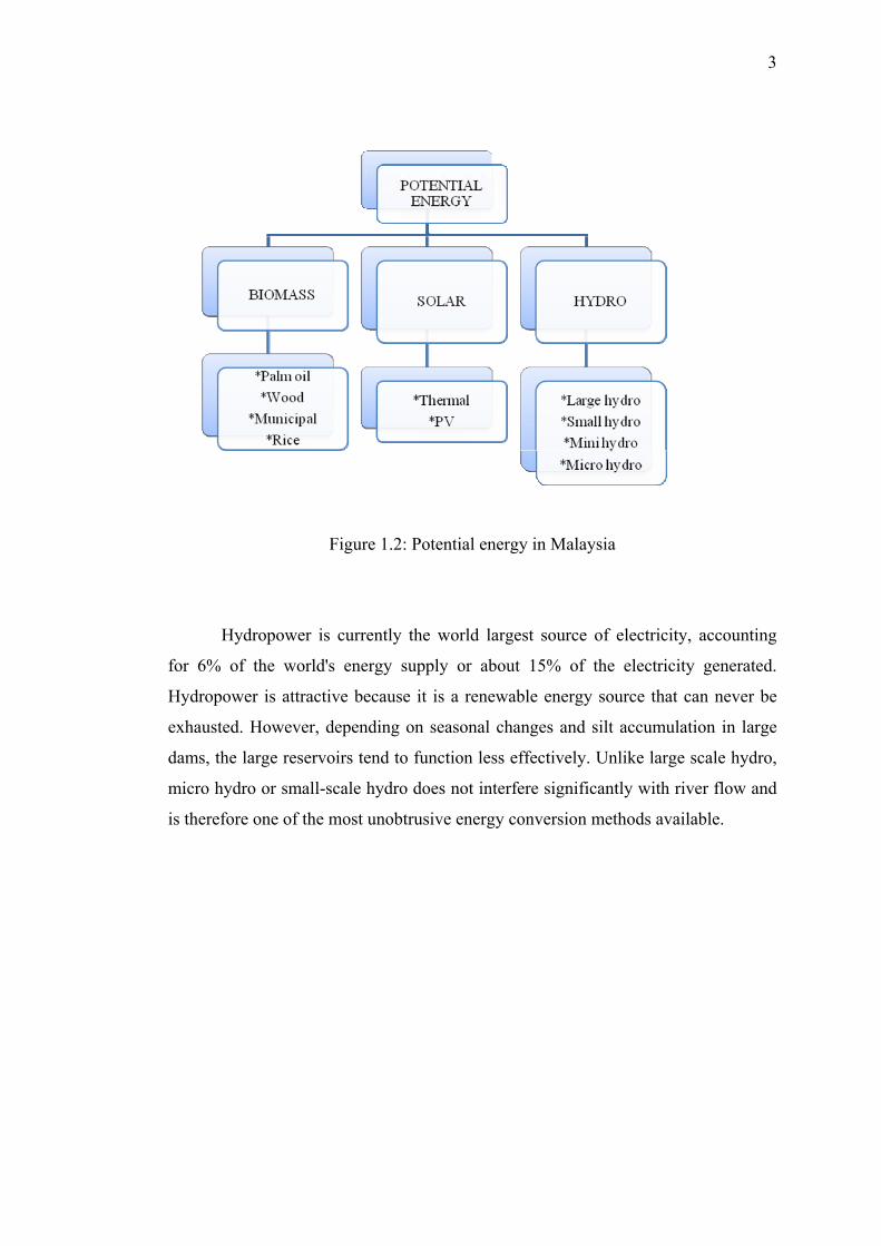
Figure 1.2: Potential energy in Malaysia
Hydropower is currently the world largest source of electricity, accounting
for 6% of the world's energy supply or about 15% of the electricity generated.
Hydropower is attractive because it is a renewable energy source that can never be
exhausted. However, depending on seasonal changes and silt accumulation in large
dams, the large reservoirs tend to function less effectively. Unlike large scale hydro,
micro hydro or small-scale hydro does not interfere significantly with river flow and
is therefore one of the most unobtrusive energy conversion methods available.
4
1.1 Classification of hydropower plants
Water can be harnessed on a large or a small scale. The categories which are
commonly used to define the power output form hydropower are outlined as follows
[2,4]:
i. Large-hydro: more than 100 MW and usually feeding into a large grid
ii. Medium-hydro: 15 - 100 MW and usually feeding a grid
iii. Small-hydro: 1 - 15 MW and usually feeding into a grid [3]
iv. Mini-hydro: between 100 kW and 1 MW; either standalone schemes
or more often feeding into the grid
v. Micro-hydro: ranging from a few hundred watts for battery charging
or food processing applications up to 100 kW, providing power for a
small community or rural industry in remote areas away from the grid
[1-6].
Micro hydropower system (MHPS) is one of the popular renewable energy
sources in the developing countries. Most of the MHPS operate in isolated mode
supplying the electricity in the local rural area where the population is very small and
sparsely distributed and the extension of grid system is not financially feasible
because of high cost investment required for transmission line. Hydroelectric power
is the technology of generating electric power from the movement of water through
rivers, streams, and tides. Water is fed via a channel to a turbine where it strikes the
turbine blades and causes the shaft to rotate. To generate electricity the rotating shaft
is connected to a generator which converts the motion of the shaft into electrical
energy. Advantage of using water resources is that hydraulic works can be made
simple and large constructions, such as dams, are not usually required. Dams, which
exploit the kinetic energy of water by raising small quantities of water to heights
through the use of regulated pressure valves, can provide water for domestic uses and
for agriculture in areas that are moderately higher than adjacent water courses.
Generally, in an autonomous micro hydropower system is designed to operate in
5
parallel with local power grids. The main reasons are to obtain economic benefit of
no fuel consumption by micro hydro turbines, enhancement of power capacity to
meet the increasing demand, to maintain the continuity of supply in the system, etc.
In a micro .hydropower system, frequency deviations are mainly due to real power
mismatch between generation and demand.
Today, most of rural area in Malaysia are still not readily accessible of grid
power. Regarding to distance and terrain, the cost of connection to the electricity
supply grid can be high and the common low load which caused to low payback have
escalating the constraint for electric utility to connect power grid into the remote
areas. Therefore, generally people in rural area will obtain electricity supply by using
diesel generators which operated by using fossil fuel. This seems to be the easiest
conducted solution due to the obstacle. However, world’s supply of fossil fuels is
now becoming scarce and depleting with increasing hazard of global warming. As a
result, people in rural area have to afford high cost of electricity generation of diesel
generators. Furthermore, the high transportation cost has worsened the situation.
Concerning to this situation, an alternative means of energy production should be
explored further. Among the available alternative energy sources, interest is focused
on clean and environmentally friendly sources that are renewable energy sources
such as wind, solar, hydro and so on.
Due to location of rural area, and common low load demand, interest is
focused on Stand Alone power systems (SPS) such as micro hydro which is easy
been constructed and maintained. SPS formerly known as Remote Area Power
Supply systems (RAPS) is the power system that are not connected to the grid. Study
has proving that small scale hydro system will only bring very slight side effects on
environment compared to large scale hydro power plant. This is because, micro
hydroelectric power system can be installed in small rivers or streams while large
scale hydroelectric power system requires huge dam or reservoir to store water which
will destroying huge area of rainforest thus cause to ecology problems.
The main components of a Micro Hydroelectric Power Plant (MHPP) may be
classified into two groups such as the hydraulic system components and the electric
system components formed by the synchronous generator and his control system.
The water's flow is fixed at the maximal value to guarantee the maximal mechanical

6
power. The upstream hydraulic part of the MHPP consists of water supply from a
river, a feeder canal, a regulation basin, a pressure pipeline whose section is accorded
to the flow and the available power. Nozzles direct water jet against a series of spoon
shaped buckets mounted around the edge of a turbine. The system ensures the
hydraulic energy transformation into mechanical energy. The wheel of the turbine is
coupled to a synchronous generator. The general diagram of this system is
represented in Figure 1.3. The Pelton turbine is used for the high falls and small
flows. It Consists of a set of specially shaped buckets mounted on the periphery of a
circular disc. It is turned by jets of water discharged from one or many nozzles which
strike the buckets which is shown in Figure 1.4. By a mobile needle inside the nozzle
we can adjust the flow. It's moved by an electric servo motor, this servo motor must
be relatively slow to minimize the water hammers effect [7].
Figure 1.3: Synoptic diagram of a MHPP .

7
Figure 1.4: The geometrical shape of a Pelton turbine.
1.2 PROJECT BACKGROUND
This research is using the MATLAB SIMULINK software to build the modelling
and regulation of the output power of a micro hydroelectric power system. This
modelling is built depends on the real parameters which are setting first such as the
voltage, frequency and so on to produce the power output is less than 100 kW.
1.3 PROBLEM STATEMENT
In the light of increasing electricity demand, international agreements to reduce
greenhouse gases limiting the use of fossil energy and environment problems. As an
environmental problem of the global warming, reducing the discharge of greenhouse

8
gas such as carbon dioxides (CO ) becomes a big objective on the world. It is 2
necessary to introduce more renewable energy for future electric power system.
There are many kinds of alternative clean and environment friend resources, such as
wind, solar and micro hydro power generation, which are very appropriate for
improving our environment conditions. In this project, the micro hydro generation as
energy resources usually serve for a local load and not require for high voltage
transmission lines crossing through rural and urban landscapes are choosen. By
implement this research, the electricity can be supply in the small or local rural area
beside that it can be cut cost investment required for transmission line.
1.4 PROJECT OBJECTIVE
The objectives of this research are to:
a) Investigate the micro hydropower system design problem
b) Develop the modelling of micro hydropower system structure using
MATLAB SIMULINK
c) Test the system of modelling micro hydropower system design using
MATLAB SIMULINK
d) Generate the electricity using the modelling was build.
1.5 SCOPE PROJECT
This research concerned about the implementation of MATLAB SIMULINK
software to build the modelling and regulation output power of a micro hydroelectric
power system design. To design this modelling, the actual parameters of micro
hydroelectric plant such as the water flows, types of turbine, head and other
parameters must be known.

9
1.6 Thesis Outline
This thesis consists of five chapters. The current chapter mainly presents the
background, objective and significance of this research. It also provides the general
development of method used in the modelling of micro hydroelectric power system.
Chapter 2 consists of previous studies and research that are relevance in
determining the placement of modelling of micro hydroelectric power system. In this
chapter also discusses about the important equipment to build the micro hydroelectric
power system.
Chapter 3 discussed the methodology that is used for this study. It details the
process that has been carried out for the short listing of alternatives and the steps
taken in building the micro hydroelectric power system design.
Chapter 4 details the analysis and the result of the study. In this chapter is
discuss about the data and calculation to build the modelling of micro hydroelectric
power system. The comparison results are also discussed in this chapter.
Chapter 5 discusses and concludes the findings of this thesis, and review the
parameter of the future development.

10
CHAPTER 2
LITERATURE REVIEW
2.1 Introduction
Malaysia has extensive electricity coverage, including rural areas. Micro hydro is
often used in autonomous or semiautonomous applications to replace diesel
generators or other small scale power plants or to provide electricity to rural
populations. Ninety-five percent of the rural population is served through the grid.
Even the more isolated areas are serviced through diesel generators, solar, and mini-
hydro sources.
The common barrier in the development of micro hydro project is the capital
cost which is relatively higher than conventional power plant. Maximising local
content by utilizing locally manufactured components and designing correct
components selection and sizing with appropriate operation strategy will
alternatively reduce the project costs. Financial and technical assistance is relatively
important in facilitating the development of micro hydro power in Malaysia
Interest in using renewable energy technologies to provide electricity to rural
and remote areas as a cost effective alternative to grid extension is gathering
momentum in many developing countries. Governments are recognizing geographic
rural areas that are non-viable for grid extension to be equipped with the renewable
energy technology. This further supported by the policies interventions and subsidies
11
programs for rural electrification. This is happening worldwide. Examples of Asian
countries with explicit mandates for renewable energy for rural electrification
include Bangladesh, China, India, Indonesia, Nepal, the Philippines, Sri Lanka,
Thailand, and Vietnam.
Indonesia, Thailand, Vietnam and other Asian and African countries have micro
hydro projects implemented which in most cases implementing standardized
technologies for off grid decentralized village hydro schemes. In some cases the
micro hydro systems are used as an alternative to the diesel generators and some of it
are applied as hybrid systems with solar power. Although small scale hydro power
applies a basic technology but recently it attracts worldwide interest because it
contribute power at low annual running cost and less technical complication [8].
2.2 Micro Hydro Power System
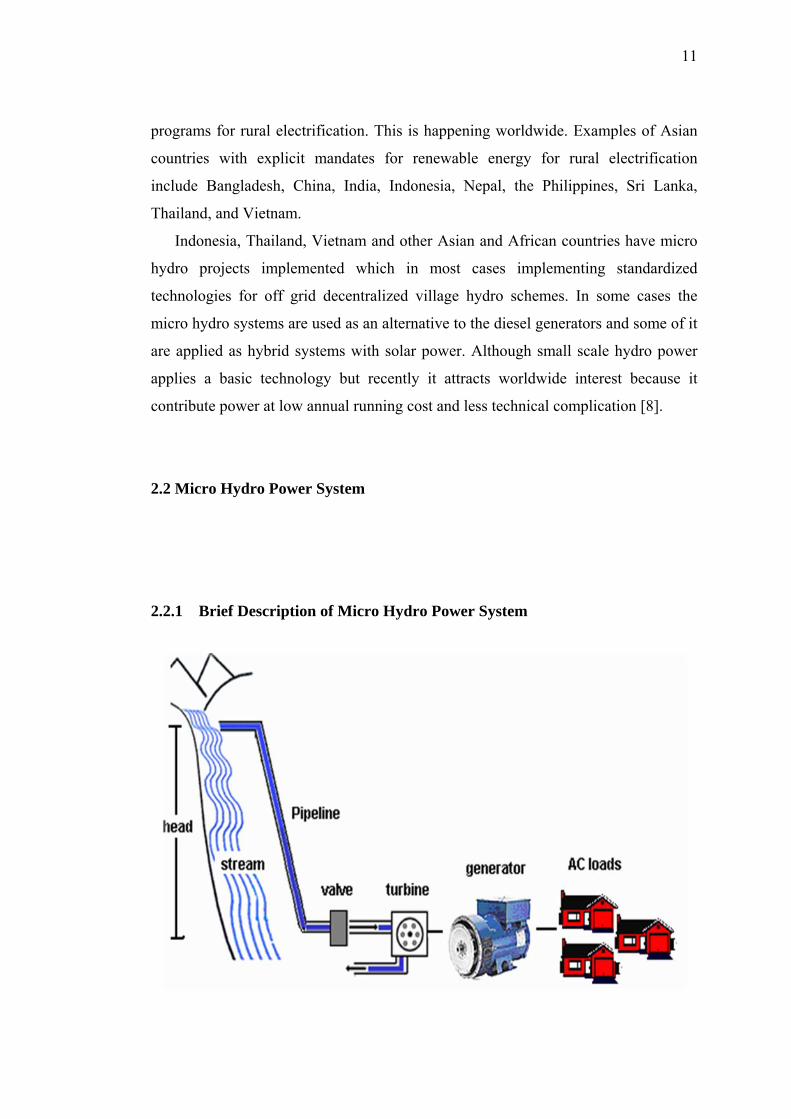
2.2.1 Brief Description of Micro Hydro Power System

12
Figure 2.1: Typical micro-hydro systems
Figure 2.2: Flow rate, Q and Head, H of a stream
Table 2.1: Categories of streams’ head
TYPE HEAD (meters)
High head ≥100
Medium head 30-100
Low head 2-30
Generally, there are two types of micro hydro system, flow of stream and
storage type. However, in this research, the system based flow of stream as Figure
2.1 is chosen as the capital cost is lesser compared to storage type and easier been
conducted. A micro hydro system converts the potential energy of water into
electricity by the use of flowing water. This water flows in water streams with
different slopes giving rise to different potential for creating heads, varying from
river to river. The capacity of power is depends on the head and flow rate as Figure
2.2.

13
2.2.1.1 Head
The head, H (in meters) is the vertical height difference between where the water
would enter the intake pipeline or penstock and turbine. Hydro sites can be
categorized according to the available head as shown in table 2.1. For hydro system,
the greatest fall over the shortest distance is preferable when choosing a hydro site.
However, more head is usually preferable since power is the product of head and
flow. So, less flow is required at a higher head to generate similar amounts of power.
With a higher head, the turbine is able to run at a higher speed. If a high head is
available, a smaller turbine and generator might be necessary for the same flow and
the water conveyance system can also be smaller and thus less costly.
2.2.1.2 Water Flow
The water volume is simply measured as the flow rate, Q (in cubic meters per
second) of the water which is usually limited by the size of the stream. The larger the
stream the more water is available for a hydro development. However, there is not all
the water can be diverted from a river for use in power production, as water must
remain in the river for environmental reasons. Nevertheless, other solutions are
possible where no water is diverted such as storage type micro hydro system.
14
2.2.1.3 Power Generation
In micro hydro system, there are two factors determine the power potential of the
water flowing in a river or stream flow and the head. The potential power can be
determined as:
P= Flow rate(Q)× Head(H)×Gravity(g) (2.1)
Where
P = Power (W)
H = Head (m)
Q = Water flow (m3/sec)
g = gravity constant (9.81 Newton)
This potential energy will turn into kinetic energy when the water falls down
over the head through the pipeline. This kinetic energy is kind of pressure which will
rotate the shaft of hydraulic turbine. Mechanical energy from turbine then will drive
synchronous generator to produce electricity in term of alternating current (AC). The
electricity will then be distributed to residences. The AC power supply must be
maintained at a constant 50 or 60 cycles/second for the reliable operation of any
electrical equipment using the supply. This frequency is determined by the speed of
the turbine which must be very accurately governed. The best geographical areas for
exploiting micro-hydro power are those where there are steep rivers flowing all year
round, for example, the hill areas of countries with high year-round rainfall, or the
great mountain ranges and their foothills.

15
2.3 Basic Components of Micro hydro System
The basic parts of micro hydro systems are [9]
i. Pipeline (penstock) - to deliver the water.
ii. Turbine - to transform the energy of the flowing water into rotational energy.
iii. Alternator or generator - to transform the rotational energy into electricity.
iv. Shut off valve – to immediate shut down the system by cut off water input.
v. Battery bank (optional) - to store the low voltage DC electricity, and usually
an inverter which converts the low voltage DC electricity into AC electricity
(i.e. 230/400V).
2.3.1 Pipeline
Pipeline used to feed water to the turbine in micro hydro system. The water should
pass first through a simple filter to block debris that may clog up or damage the
machine. It is important to use a pipeline of sufficiently large diameter to minimize
friction losses from the moving water. Pipelines are usually made from PVC or
polyethylene although metal or concrete pipes can also be used. Polyethylene pipe

16
may be used for pipe up to 100 PSI, PVC to 160 and 350 PSI and some steel pipe
may be specified to 1000 PSI. Water hammering is caused by the rapid loss of
momentum of the water in the pipe and this kinetic energy must go somewhere so the
pipe contorts, expands and bangs against the interior of the walls to absorb the stress.
The same affect will take place in a penstock with long runs with a high rate of flow.
Therefore, ensure the pipe and gate valves are able to withstand these forces. When
possible, the pipeline should be buried in order to stabilize the pipe and prevents
critters from chewing it.
2.3.2 Turbine
Table 2.2: Turbines with the efficient operating head range
Turbine type Head range, H (m)
Kaplan and Propeller 2 < H < 40
Francis 10 < H < 350
Pelton 50 < H < 1300
Banki-Michell 3 < H < 250
Turgo 50 < H <250
The turbine will extract energy from the flowing water, and turn it into mechanical
energy that turns the generator to create electrical energy. System efficiencies range
between 65% and 80% depending upon the turbine style and design. Turbines need
to be robust machines, and the best use steel (rather than plastic). A turbine selection
is largely determined by the head under which it operates. Besides, turbines are also
divided by their principle way of operating and can be either impulse or reaction
turbines. Impulse turbines convert the kinetic energy of a jet of water to mechanical
17
energy such as Pelton turbine, Turgo turbine, Cross flow turbine and etc. While,
reaction turbines convert potential energy in pressurized water to mechanical energy
such as Francis turbine, Propeller turbine, Kaplan turbine and etc. Table 2.2 shows
the various types of turbines; each operates most effectively in a certain pressure and
flow range.
2.3.3 Generator
There are many types of generators such as synchronous generator, inductor
generator, and DC generators. Synchronous generator used in almost all standalone
applications. While, induction generator used most often with grid tie systems. DC
alternator produces rectified alternating current, and it is easy to service. The turbine,
generator, and electrical control boxes should all be "housed" in a weather proof
building. The building should resist inclement weather, animals, and intruders
(children & unwelcome visitors). Regarding to these, a sturdy lock is recommended.
2.3.4 Shut-off Valve
A shut-off valve is necessary, and should be directly in front of the turbine in case an
immediate shutdown of the system is required. This valve should be of high quality
and very durable. It is recommended that the switch of valve controller should be in
normally close condition which mean the valve should be in open position then do
not function when most needed.

18
2.3.5 Battery bank
Normally, lead-acid deep cycle battery will be used in micro-hydro system. Since the
energy consumption of users are not consistently, so the battery bank can be charged
during less energy consumption time. Battery bank then can compensate when there
is overloading condition where energy needed greater than the micro hydro
producing. During the dry season the average rainfall is undeniably lower than wet
season, however, many streams still able to reach to the minimum requirement of
river flow. Hence, an assumption of water source might always within the minimum
range throughout the year, so in this research, micro hydro system proposed without
storage system. Nevertheless, by adding a battery bank to the micro hydro system
can guarantee a never ending supply of energy. Batteries used by a micro hydro
system will last longer than those used by other energy systems, as they will not
discharge as deeply and as frequently as others do.
2.4 Software used
2.4.1 MATLAB Simulink
Simulink (Simulation and Link) is an extension of MATLAB by Mathworks Inc. It
works with MATLAB to offer modelling, simulation, and analysis of dynamical
systems under a graphical user interface (GUI) environment. The construction of a
model is simplified with click and drag mouse operations. Simulink includes a
comprehensive block library of toolboxes for both linear and nonlinear analyses.
Models are hierarchical, which allow using both top down and bottom up
19
approaches. As Simulink is an integral part of MATLAB, it is easy to switch back
and forth during the analysis process and thus, the user may take full advantage of
features offered in both environments.
2.5 Technology developments
2.5.1 Modelling and regulation of a micro hydroelectric power plant [7]
The research made by Issam Salhi, Mohammed Chennani, Saïd Doubabi and Nabil
Ezziani from faculty of science and technology of Marrakesh, Morocco. This paper
presents how to develop a mathematical model for a micro hydroelectric power plant
(MHPP). This paper validate the model by analysing a MHPP prototype's
performances. The Prototype is installed in the laboratory. This research used
downstream regulation which ensures good frequency regulation results. The used
controller is the 'PI' one. The practical results obtained are similar for those in
simulation.
2.5.2 A self-excited synchronous generator for small hydro applications [10]
The research made by Hilmy awad, Mohamed wadi and Essam hamdi from
Chalmers University of Technology, Sweden. This paper describes a class of self-
excited synchronous reluctance generators (SRG) and presents preliminary test
results obtained from an experimental machine. The concept of SRG described in
this paper not only has the advantages of simplicity and ruggedness, but can also
have enhanced steady-state characteristics and high efficiency over a wide range of
operation. Additionally, its output frequency is determined only by the prime mover

20
speed and this enables integration with power electronic devices to realise control
schemes more economically. This proposed design provides a competitive alternative
to both induction and conventional brushless synchronous generators used in stand-
alone applications.
2.5.3 Planning of Micro-grid Power Supply Based on the Weak Wind and
Hydro Power Generation [11]
This research made by Zulati Litifu, Noel Estoperez, Mostafa Al Mamun, Ken
Nagasaka, Yasuyuki Nemoto and Izumi Ushiyama from Department of Electrical
and Electronics, Tokyo University of Agriculture and Technology. This paper
presents the installation and verification processes of Micro Hydro Power Plant
(MHPP) and Micro Wind Power Turbine (MWPT) for Kuromori Mountainous
Region of Yamanashi Profecture based on the Planning Project of COE Program.
This paper focuses on the technologies to develop and utilize the natural energy in a
region where the Average Wind Speed (AWS) and water discharge are relatively
weak just like the most other regions in this prefecture. Micro-grid (MG) consisting
of MHPP and MWPT sources are to be installed in Existing Power System (EPS).
Contribution of MHPP and MWPT are determined by investigated wind and water
characteristics on complex shaped mountainous land. Stability and reliability of the
new hybrid power system are proved by using the compound controllers. Benefit
from MG of MHPP and MWPT is proved by comparing the environmental and
financial efficiency before and after installing the MG. This paper, with the
important practical significance, indicated that regions with relatively weak natural
energy may be developed by applying the MG with possible compensation between
micro sources.
2.6 Conclusion

21
As a conclusion all the findings from the previous method will be
accumulatively used to gain more knowledge on the topic and at the same time
improving the result by identifying the weaknesses from the previous research. By
revisiting the previous research, the quality of this thesis can be improved and give
more impact in the development of distribution system.
CHAPTER 3
METHODOLOGY
3.1 Introduction
This chapter will be described the methods that has been implement in this
research. This research implementation method will be divide into 4 phases in
order to make everything more systematic, manageable and easier to
troubleshoot. Below is the 4 phases that will be done throughout this
research:
i. Phase 1 : Project planning
ii. Phase 2 : Project research
iii. Phase 3 : Project development
iv. Phase 4 : Project verification and analysis

22
Phase 1
Project planning
Phase 2
Project research
Phase 3
Project development
Phase 4
Project verification and analysis
Begin
End

23
Figure 3.1 : Flowchart of Overall Project Development
3.1.1 Phase 1 : Project Planning
The project planning is most important to develop the project because it is involving
the whole processes from the project title until the end. It also as a guideline for
project implementation. At this phase, the title of project is choosing after have a
discussion with the supervisor. From the discussion that have done, the problem
statement, objective and the scope of limitation have been identified to develop this
project.
At this stage, the type of software will be using in this project is identified.
The MATLAB Simulink software will be using to design the modelling of the micro
hydropower system.
3.1.2 Phase 2 : Project Research
In this phase, the research of the project that will be developing is done and the
software that will be used in this project has been studied. By this way, it will make

24
easier to work on this software because the understanding about this software has
been studied.
During the research, the books, thesis and journal are also used to get the
information for developing this project. A few websites that are related with this
project has been surfing in order to get more information to develop this project.
3.1.3 Phase 3 :Project Development
In the system development phase, the parameter that are normally used in micro
hydro system are collected. After that, the MATLAB Simulink will be used to design
the modelling of the micro hydro system.
3.1.4 Phase 4 :Project Verification and Analysis
The last phase of this research is, the modelling that has been designed will be tested
to make sure it operates successfully or not. If the modelling design is not operated
the analysis of this project will be occurred to identify the problem to make sure this
modelling design work successful.
25
REFERENCES
[1] R. Billinton, R. Karki, 2001. "Maintaining Supply Reliability of Small
Isolated Power Systems Using Renewable Energy", IEE Proceedings -
Generation, Transmission and Distribution, Vol. 148, No. 6, November, pp.
530-534.
[2] P. Fraenkel et al, Micro-hydro power – A guide for development work,
Russell Press Ltd., Nottingham, UK, 1991.
[3] J. J. Fritz, Small and mini-hydro systems, McGraw-Hill Book Company, New
York, 1984.
[4] P. Garman, Water current turbines, Russell Press Ltd., Nottingham, UK,
1986.
[5] D. Hislop, Energy options – An introduction to small-scale renewable energy
technology,
Intermediate Technology Publications, Portsmouth, UK, 1992.
[6] N. Smith, Motors as generators for micro-hydro power, Russell Press Ltd.,
Nottingham, UK, 1996.
[7] I. Salhi, M. Chennani, S. Doubabi, N. Ezziani, "Modeling and regulation of a
micro hydroelectric power plant," in CReSTIC – Iut de Troyes,9, rue de
Québec B.P. 396 – F-10026 Troyes cedex , France, 2008.
[8] M. A. M. Badrin, "Micro Hydro Power," Malaysia, 2009.
[9] Japan International Coorporation Agency, Manuals and Guidelines for Micro-
hydropower Development in Rural Electrification, Japan: Department of
Energy (DOE), 2009.
[10] H. Awad, M. Wadi, E. Hamdi, "A self excited synchronous generator for
small hydro application," Department of Energy and Environment, Sweeden,
2001.
26
[11] Z. Litifu, N. Estoperez, M. Al Mamun, K. Nagasaka, Y. Nemoto, I.
Ushiyama, "Planning of microgrid power supply based on the weak wind and
hydro power generation," in Century Object of Existing Program of Tokyo
University of Agriculture and Technology under Grand of Ministry Education
and Culture, Japan, 2006.
[12] "Hydraulic Turbine And Turbine Control Models For System Pynamic
Studies," Working Group on Prime Mover and Energy Supply, vol. 7, no.
Transactions on Power Systems, pp. 167-174, 1992.
[13] J.M. Undriil and J.L. Woodward, 'Non-Linear Hydro Governing
Model and Improved Calculation for Determining Temporary
Droop'. IEEE Trans., Vol. PAS-86, No. 4, pp. 443-453, April 1967.
[14] P.B. Schmidt, M.L. Gasperi, G. Ray, A.H. Wijenayake, "Initial Rotor Angle
Detection Of A Non-Salient Pole Permanent Magnet Synchronous Machine,"
in New Orleans, Louisiana, Milwaukee, Wisconsin, 1997.
[15] J.D Law, "Steady State Analysis Of Salient Pole Synchronous Generators,"
ECE 523, United States, 2007.
[16] S. Mansoor, “Behaviour and Operation of Punped Storage Hydro
Plants”, doctoral thesis, University of Wales, April 2000.
[17] A. Kjolle, “Hydropower in Norway” Mechanical Equipment,
Trondheim, December 2001