modelling of lqr control with matlab - humusoft · · 2006-10-06modelling of lqr control with...
TRANSCRIPT

MODELLING OF LQR CONTROL WITH MATLAB
J. Vondřich, E. Thőndel
Department of Mechanics and Materials Science, Faculty of Electrical Engineering, CTU in Prague
Abstract
In the paper is used LQR control for regulation of the pressure in air-operated spring
of the absorber of the vibrating mechanical system. The LQR is the control, which
minimizes the accuracy of control opposite power exacting. The LQR control radiates
from complete vector states, which in real life must be not in the feedback to position.
In our case, we have to dispose the output parameters from the accelerometers.
1 Model of the mechanical systemConsider the vibrating system as a mechanical system, which is compiled of a driven motor,
gearbox and mechanisms with elastic and damping parts and driven parts. Vibration transmitted the to
the frame of this system is possible due to unbalanced rotors and mechanisms, the crank gear of the
engine or oscillation of the moving driven parts.
The amplitude of the induced vibration is a function of the applied force and its frequency. An
exciting force has the greatest effect when applied at the fundamental frequency of the system. The
system is then excited at resonance, and in the case of a lightly damped system, the induced movement
can be many times greater than the deflection caused by the equivalent static force. The ratio between
the two effects is called the magnification factor. Vibrations in a structure have this effect. The very
high peak accelerations can mean that the effective weight of the vibrating system increases several-
fold, and this may cause its destruction. The vibration absorber is advantageous primarily in that it
reduces the amplitude of the vibrations in the system by an oscillating force F(t) acting (Fig. 1), for two
alternatives from an unbalanced rotor on the system:
I. F(t)=meω2sinωt=Fsinωt, where m is the mass of the unbalanced rotor, e is the
eccentricity of the unbalanced rotor and ω is the angular velocity of the unbalanced
rotor,
II. squere wave course of acting force F(t) with the amplitude force F and frequency ω.
The model of system with reduced mass m1 and affiliate mass m2 of the absorber is possible to
illustrate as a two mass system located on two springs with coefficients of elasticity k1 and k2 and
coefficients of stiffness b1 and b2 (Fig.1). The spring 2 is air-operated sprig and the absorber is the
affiliate mass 2. The equations of motion for the model are
).()(
,)()(
12212222
)(122111221111
yybyykym
Fyybybyykykymt
&&&&
&&&&&
−−−−=
+−+−−+−= (1)
m 2
k2
k1
F (t)
y 2
y1
m 1
FactCONTROL
a
a
Fig. 1 The model of the mechanical system with an affiliate control absorber

The possibility to reduce the vibration is the tuneable absorber, where an air-operated spring
with changed coefficient of elasticity k2 through the changed pressure supply of the air is incorporated.
Substituting y1=Y1eiωt
and y2=Y2eiωt
in equations (1) yields two simultaneous equations (reason of the
influence of the damping b1, b2 of the springs are very small):
,,)(
2
2
2
21
1F
a
kYF
a
mkY =
−
=
ω
(2)
with .))((2
2
22
2
121kmkmkka −−−+= ωω (3)
These equations define the dynamics of the system with one-degree of freedom after it has
been modified by attaching the secondary mass/spring system. The extra mass and spring are the
absorber. Ideally, we completely want to stop the vibration of primary mass m1. We can do this by
setting Y1=0 in the first equation (2). This yields:
,
2
2
m
k=ω or .
2ωω = (4)
That is, if the natural frequency of the added mass-spring system itself is the same as the
excitation frequency, the primary mass will stop moving. What this means is that we can tune an
absorber to single excitation frequency. The second equation (2) can be rearranged to find out how
much the secondary mass m2 will be vibrate:
.
2
2
k
FY
−
= (5)
This indicates that providing the original system is being driven by a force input, the motion of
the added mass is bounded. It does not go infinite, even though it is being excited at a frequency that
matches its original natural frequency.
2 Design of the parameters of the absorberA wheel of m1=350 kg rotates at n=48 revolutions per minute. A misbalance e= 1.7 mm in the
wheel means that when it is running it produces a peak force of
.152
1NemF == ω (7)
Assume there is a maximum permissible absorber deflection of Y2=50 mm. The motion of the
secondary mass m2 is given by the equation (5), Assuming we use the entire clearance for the motion
of the absorber. We can calculate the absorber stiffness as:
.30005.0
15 1
2
2
−
=== Nmy
Fk (8)
Recall that for the absorber to work, its natural frequency (before it is fastened to the vibrating
system) is the same as the excitation frequency (4):
.125
300
22
2
2kg
km ===
ω
(9)
The result of this solution is shown in the graph of the function in dimensionless variables of
the amplitude characteristic dependence displacements y1/y2 and angular velocities ω/ω2 of the
absorber m2 (Fig.2). The affiliate mass m2 of the absorber is not moveable in the case when the ratio
ω/ω2=1.The next result is the phase characteristic. The change of the motion of the affiliate mass m2
of absorber is 180o
in area when the ratio ω/ω2=1 (Fig. 3).
3 LQR control of the tuneable absorberThe possibility to reduce the vibration by the transient state is the tuneable absorber, where an air-
operated spring with changed coefficient of elasticity k2 through the changed pressure supply of the air is
incorporated.

0.6 0.7 0.8 0.9 1 1.1 1.2 1.3 1.4 1.5 1.6
0
0.5
1
1.5
2
2.5
3
3.5
4
4.5
5
x 10-3
w/w2
y1/y
2
Amplitude Characteristic
Fig. 2 The amplitude characteristic on dimensionless variables (without the absorber is stroke course)
0.6 0.7 0.8 0.9 1 1.1 1.2 1.3 1.4 1.5 1.6
-180
-160
-140
-120
-100
-80
-60
-40
-20
w/w2
Phase [
deg]
Phase Characteristic
Fig. 3 The phase characteristic on the dimensionless variables
The model with affiliate mass m2 of the LQR control absorber changed coefficient of elasticity
k2, an accelerometer a1 located on the mass m1 and an accelerometer a2 located on the mass m2 and
control unit is shown on the Fig.1. It is possible to write the state description system and model (Fig.1)
in the form:
,
,
,,
1
1
mmm
techtechactactmm
techtechactact
DuCxy
LCFBFBAxx
DuCxyFBFBAxx
+=
+++=
+=++=
&
&
&&
(10)
where A is the state matrix, C the state matrix of output, D is the matrix of the coupling between input
and output, Fact is the control force in the air-operated spring, Ftech is the spurious force from the
technological process, Bact is the matrix of the input a control, Btech is the matrix of input of the
spurious force, xm is the state vector of the model, y1m is the displacement of the model and vector of
input u is
,.mactxGF −= (11)
where G is the matrix of control. It is possible to obtain this state bond with the help of the
minimization of the integral criterion on the LQR (Linear Quadratic Regulator) control [1,2]
,)(0
dtFRFxQxJact
T
act
T⋅⋅+⋅⋅= ∫
∞
(12)
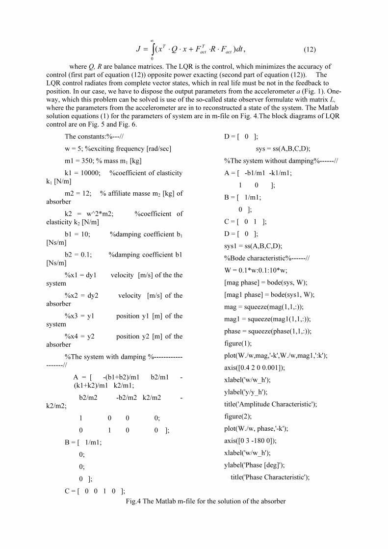
where Q, R are balance matrices. The LQR is the control, which minimizes the accuracy of
control (first part of equation (12)) opposite power exacting (second part of equation (12)). The
LQR control radiates from complete vector states, which in real life must be not in the feedback to
position. In our case, we have to dispose the output parameters from the accelerometer a (Fig. 1). One-
way, which this problem can be solved is use of the so-called state observer formulate with matrix L,
where the parameters from the accelerometer are in to reconstructed a state of the system. The Matlab
solution equations (1) for the parameters of system are in m-file on Fig. 4.The block diagrams of LQR
control are on Fig. 5 and Fig. 6.
The constants:%---//
w = 5; %exciting frequency [rad/sec]
m1 = 350; % mass m1 [kg]
k1 = 10000; %coefficient of elasticity
k1 [N/m]
m2 = 12; % affiliate masse m2 [kg] of
absorber
k2 = w^2*m2; %coefficient of
elasticity k2 [N/m]
b1 = 10; %damping coefficient b1
[Ns/m]
b2 = 0.1; %damping coefficient b1
[Ns/m]
%x1 = dy1 velocity [m/s] of the the
system
%x2 = dy2 velocity [m/s] of the
absorber
%x3 = y1 position y1 [m] of the
system
%x4 = y2 position y2 [m] of the
absorber
%The system with damping %------------
-------//
A = [ -(b1+b2)/m1 b2/m1 -
(k1+k2)/m1 k2/m1;
b2/m2 -b2/m2 k2/m2 -
k2/m2;
1 0 0 0;
0 1 0 0 ];
B = [ 1/m1;
0;
0;
0 ];
C = [ 0 0 1 0 ];
D = [ 0 ];
sys = ss(A,B,C,D);
%The system without damping%------//
A = [ -b1/m1 -k1/m1;
1 0 ];
B = [ 1/m1;
0 ];
C = [ 0 1 ];
D = [ 0 ];
sys1 = ss(A,B,C,D);
%Bode characteristic%------//
W = 0.1*w:0.1:10*w;
[mag phase] = bode(sys, W);
[mag1 phase] = bode(sys1, W);
mag = squeeze(mag(1,1,:));
mag1 = squeeze(mag1(1,1,:));
phase = squeeze(phase(1,1,:));
figure(1);
plot(W./w,mag,'-k',W./w,mag1,':k');
axis([0.4 2 0 0.001]);
xlabel('w/w_h');
ylabel('y/y_h');
title('Amplitude Characteristic');
figure(2);
plot(W./w, phase,'-k');
axis([0 3 -180 0]);
xlabel('w/w_h');
ylabel('Phase [deg]');
title('Phase Characteristic');
Fig.4 The Matlab m-file for the solution of the absorber

∫Bact
u
C
x& x
A
D
Btech
Btech
Bact
Fact
Fact
Ftech
L
error
∫ C
y1
y1m
A
D
-G
u mx&
mx
Fig. 5 LQR control block diagram for the control absorber
Fig. 6 The block diagram of LQR control
If we use the air-operated spring with the changed coefficient of elasticity k2 with thepossibility of regulation of the pressure pact air in dependence to the displacement y1, it is possible toreduce this displacement y1 on the minimum. It is possible change some dependence for a pressure inthe rubber bellows in the air-operated spring as the calculated force Fact . The coefficient of elasticityk2 of the air-operated spring is
,2
2
V
SFk
actγ
= (13)
where γ is the ratio of specific heats for air, S is the effective cross-sectional are of the bellows for the air-
operated spring. and V is the volume of the bellows.

4 Results
The present article discusses also a method of vibration control LQR for a structure by usingthe vibration absorber without damping. In the method, a variable stiffness vibration absorber is usedfor controlling the principle mode. The stiffness is controlled by the accelerometers a under the auto-tuning algorithm for creating an anti-resonance state. The optimal vibration absorber with dampingwith the air-operated spring is also utilized for controlling higher modes. The analyses and Matlab m-file for the auto-tuning control are developed. A method to obtain the optimal parameters has beenpresented for the vibration absorber, which controls higher modes. In order to validate the controlmethod and the analysis, experimental tests will be carried out in the next phase of research.
Vibrations of machines and structures vanish perfectly at a certain frequency when they have avibration absorber without damping. But if forced frequencies vary from the anti-resonance frequency,their vibration amplitudes increase significantly. Then, the absorber without damping cannot beapplied to the structure subjected to variable frequency loads or to the loads having high frequencycomponents. A vibration absorber can be used to eliminate unwanted steady-state vibrations from aone-degree of freedom system. We do this by tuning the natural frequency of the absorber (by itself) tothe excitation frequency. The following must be kept in mind when designing an absorber: Thevibration of the primary mass is reduced to zero (for no damping), or very small (with light damping).However, this is only at a single operating speed. If the system operates over a wide speed range, thevibrations away from the absorber frequency may still be large. The original system had one-degree offreedom. The modified system has an additional natural frequency. One of the new natural frequencieswill be lower, and one higher, than the original frequency.
The difference between the two new natural frequencies, what we can solve from theequations (1) depends on the ratio of the secondary to primary masses m2/ m1. The bigger the massratio, the further apart are the new natural frequencies.
Fig. 7 The displacement y2 after starting (10 sec) of LQR control (alternative I)
Fig. 9 The displacement y1 after starting (10 sec) of LQR control (alternative I)

Fig. 9 The displacement y2 after starting (10 sec) of LQR control (alternative II)
Fig. 10 The displacement y1 after starting (10 sec) of LQR control (alternative II)
The aim of the paper is to acquaint the order with design of the incorporated absorber to thevibration of system, which makes possible the reduction of the vibration of the system to a minimum.In the case when the frequency ω of the acting force F(t) (alternative I and II) driving the system is thesame as frequency ω2 of the vibration of the affiliate mass m2 of the absorber is the displacement ofthe mass m1 after starting (t=10 sec) of LQR control y1= 1,95 mm (Fig. 8) for the alternative I and forthe alternative II is the displacement of the mass m1 after starting (t=10 sec) of LQR control y1= 0 mm(Fig. 10). The displacements of the mass m2 the absorber is show on the Fig. 7 and Fig. 9. If we use theair-operated spring with the changed coefficient of elasticity k2 with the possibility of regulation of thepressure pact=Fact/S for the air in the operated spring in dependence to the displacement y1 of ispossible to reduce this displacement y1 on the minimum (Fig. 8).
References
[1] G. F. Franklin, J. D. Powell, M. L. Lewis. Control of Dynamic Systems Adison Wesley, NewJersey, second edition, 1990.
[2] Vl. Havlena, J. Štecha, Moderní teorie řízen Vydavatelství ČVUT, Praha, 2000.
Jiří Vondřich, [email protected], Evžen Thőndel, [email protected]