modelling of heat exchangers based on thermochemical
TRANSCRIPT

Modelling of heat exchangers based on thermochemical material for solar heat storagesystemsFopah Lele, Armand ; Rönnebeck, Thomas; Rohde, Christian; Schmidt, Thomas; Kuznik,Frédéric; Ruck, WolfgangPublished in:Energy Procedia
DOI:10.1016/j.egypro.2014.12.284
Publication date:2014
Document VersionPublisher's PDF, also known as Version of record
Link to publication
Citation for pulished version (APA):Fopah Lele, A., Rönnebeck, T., Rohde, C., Schmidt, T., Kuznik, F., & Ruck, W. (2014). Modelling of heatexchangers based on thermochemical material for solar heat storage systems. Energy Procedia, 61, 2809-2813.https://doi.org/10.1016/j.egypro.2014.12.284
General rightsCopyright and moral rights for the publications made accessible in the public portal are retained by the authors and/or other copyright ownersand it is a condition of accessing publications that users recognise and abide by the legal requirements associated with these rights.
• Users may download and print one copy of any publication from the public portal for the purpose of private study or research. • You may not further distribute the material or use it for any profit-making activity or commercial gain • You may freely distribute the URL identifying the publication in the public portal ?
Take down policyIf you believe that this document breaches copyright please contact us providing details, and we will remove access to the work immediatelyand investigate your claim.
Download date: 20. Oct. 2021

Energy Procedia 61 ( 2014 ) 2809 – 2813
Available online at www.sciencedirect.com
ScienceDirect
1876-6102 © 2014 The Authors. Published by Elsevier Ltd. This is an open access article under the CC BY-NC-ND license (http://creativecommons.org/licenses/by-nc-nd/3.0/).Peer-review under responsibility of the Organizing Committee of ICAE2014doi: 10.1016/j.egypro.2014.12.284
The 6th International Conference on Applied Energy – ICAE2014
Modelling of heat exchangers based on thermochemical material for solar heat storage systems
Armand Fopah Lelea, Thomas Rönnebecka, Christian Rohdea, Thomas Schmidta*, Frédéric Kuznikb, Wolfgang K. L. Rucka
aLeuphana University of Lüneburg, Institute for Sustainable and Environmental Chemistry, Building 13, Scharnhorststraße 1, 213 35 Lüneburg - Germany. Innovations-Incubator Project / Competence Tandem – Thermal Battery
bNational Institute of Applied Sciences, Department of Civil Engineering. Bâtiment Sadi Carnot, Campus de LA DOUA 9- France
Abstract
In solar thermal energy storage systems the operation modes involve charging and discharging. This paper focuses only on the charging leading to an endothermic reaction and therefore an efficient heat exchanger is required to transfer the heat for fast and complete charging. Two different heat exchangers are studied in this paper. A plate fin and helical coil heat exchangers embedded in a magnes ium chloride bed is modelled and solved using the software Comsol 4.3a based on finite element method. Meshing analysis is performed for parameters sensibility and the results show a temperature variation of 13 °C (helical coil) and 19 °C (plate fin) in the material bed during the charging mode of the thermochemical heat storage system. The pressure distribution in the heat transfer fluid and the temperature distribution in the material bed are presented and the calculated overall heat transfer coefficient of 173 W/m2·K (helical coil) and 236 W/m2·K (plate-fin) are obtained on the base of the total heat transferred (Q) to through the system. The fluid flow is in turbulence regime (Re = 13200) in the fin-plate, but in laminar mode (can be kept up to Re = 20000) [1] in the coil because the flow is affected by secondary flow cause by centrifugal forces. This study allows the choice of the h eat exchanger wherein with first experiment has been made and compared. © 2014 The Authors. Published by Elsevier Ltd. Selection and/or peer-review under responsibility of ICAE Keywords: Heat exchanger; Fin plate; Helical coiled tube; Thermochemical material; Heat transfer coefficient.
Nomenclature
cp specific heat capacity (kJ/kg) μ dynamic viscosity, kg/(m·s) ρ density (Kg/m3) ∆T1 Inlet temperature difference between fluid-solid (K) ∆T2 Oulet temperature difference between fluid-solid (K) q Heat Transfer rate or heat flux (W)
1. Introduction
A decade ago, it has been shown that helical coil and plate fin heat exchanger increases the heat transfer coefficient and the temperature rise of fluid fo r helically co iled depends on the tube geometry and the flow rate [2]. So, to develop a long or short term solar energy storage system using solid-gas reaction system, just like the development of thermal energy storage systems, heat exchanger is an absolute requirement in close process. In that field of thermal energy storage, various research projects [3]–[5] where different heat exchangers were used, recommend that heat exchanger
* Corresponding author. Tel.: +49-4131-677-2951; fax: +49-4131-677-2822. E-mail address: [email protected] - [email protected].
© 2014 The Authors. Published by Elsevier Ltd. This is an open access article under the CC BY-NC-ND license (http://creativecommons.org/licenses/by-nc-nd/3.0/).Peer-review under responsibility of the Organizing Committee of ICAE2014
2810 Armand Fopah Lele et al. / Energy Procedia 61 ( 2014 ) 2809 – 2813
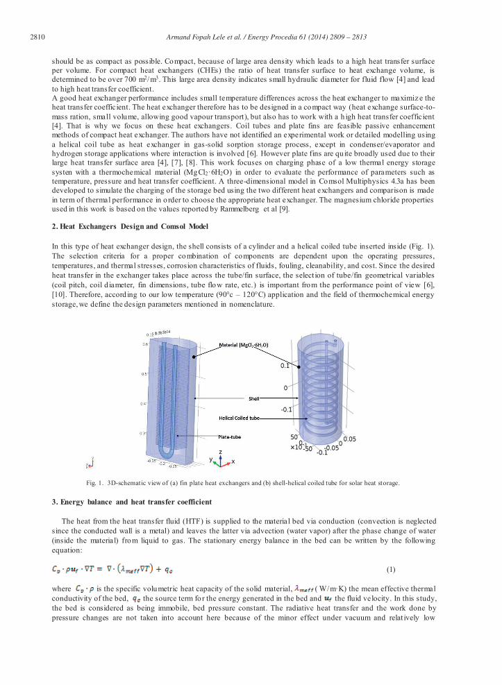
should be as compact as possible. Compact, because of large area density which leads to a high heat transfer surface per volume. For compact heat exchangers (CHEs) the ratio of heat transfer surface to heat exchange volume, is determined to be over 700 m2/m3. This large area density indicates small hydraulic diameter for fluid flow [4] and lead to high heat transfer coefficient. A good heat exchanger performance includes small temperature differences across the heat exchanger to maximiz e the heat transfer coefficient. The heat exchanger therefore has to be designed in a compact way (heat exchange surface-to-mass ration, small volume, allowing good vapour transport), but also has to work with a h igh heat transfer coefficient [4]. That is why we focus on these heat exchangers. Coil tubes and plate fins are feasible passive enhancement methods of compact heat exchanger. The authors have not identified an experimental work or detailed modelling using a helical coil tube as heat exchanger in gas-solid sorption storage process, except in condenser/evaporator and hydrogen storage applications where interaction is involved [6]. However plate fins are qu ite broadly used due to their large heat transfer surface area [4], [7], [8]. This work focuses on charging phase of a low thermal energy storage systen with a thermochemical material (MgCl2·6H2O) in order to evaluate the performance of parameters such as temperature, pressure and heat transfer coefficient. A three-dimensional model in Comsol Multiphysics 4.3a has been developed to simulate the charging of the storage bed using the two different heat exchangers and comparison is made in term of thermal performance in o rder to choose the appropriate heat exchanger. The magnesium chloride properties used in this work is based on the values reported by Rammelberg et al [9]. 2. Heat Exchangers Design and Comsol Model In this type of heat exchanger design, the shell consists of a cylinder and a helical coiled tube inserted inside (Fig. 1). The selection criteria for a proper combination of components are dependent upon the operating pressures, temperatures, and thermal stresses, corrosion characteristics of fluids, fouling, cleanability, and cost. Since the desired heat transfer in the exchanger takes place across the tube/fin surface, the select ion of tube/fin geometrical variables (coil pitch, coil d iameter, fin dimensions, tube flow rate, etc.) is important from the performance point of view [6], [10]. Therefore, accord ing to our low temperature (90°c – 120°C) application and the field of thermochemical energy storage, we define the design parameters mentioned in nomenclature.
Fig. 1. 3D-schematic view of (a) fin plate heat exchangers and (b) shell-helical coiled tube for solar heat storage.
3. Energy balance and heat transfer coefficient
The heat from the heat transfer fluid (HTF) is supplied to the material bed via conduction (convection is neglected since the conducted wall is a metal) and leaves the latter via advection (water vapor) after the phase change of water (inside the material) from liquid to gas. The stationary energy balance in the bed can be written by the following equation:
(1) where is the specific volumetric heat capacity of the solid material, ( W/m·K) the mean effective thermal conductivity of the bed, the source term for the energy generated in the bed and the fluid velocity. In this study, the bed is considered as being immobile, bed pressure constant. The radiative heat transfer and the work done by pressure changes are not taken into account here because of the minor effect under vacuum and relat ively low

Armand Fopah Lele et al. / Energy Procedia 61 ( 2014 ) 2809 – 2813 2811
temperature. Also thermal resistance of walls is neglected due to the fact that model idealize the contact heat exchanger/material bed. Based on finite element method, Comsol Multiphysics was applied to calculate the overall transfer coefficient, (W/m2·K). It is calculated from the temperature data and the total heat transferred during the charging (Equation 2).
(2) where (m2)is the outside surface area of co iled tube or p late fin, is the heat transfer rate and is the log mean temperature difference, based on inlet temperature difference, , and the outlet temperature difference,
g, using
the following equation:
(3) In this case of flu id-solid heat t ransfer, which d iffers from co-flow and counter flow, the used temperature in the solid is an average at different positions of the solid.
4. Results and discussion
The material bed in itially at 25 °C is heated up to 120 °C with uniform temperature d istribution in the both case in the simulation, see Fig. 4b. Th is variat ion of about 95 °C is in agreement with the temperature need to charge the heat storage system and which can be supplied by a solar collector. The system with a plate fin heat exchanger (right picture in the Fig. 3) exh ibits a higher temperature variation (19 °C) than one with the helical co il heat exchanger (13 °C). The p late fin with 50 plates has a bigger heat transfer surface than of the helical coil. The reason of temperature d ifference can be that the flow is affected by secondary flow cause by centrifugal forces in the helical co il. The overall heat transfer coefficient of 236 W/m2·K for plate fin heat exchanger and of 173 W/m2·K for helical co il tube heat exchanger is obtained, showing why we should use the plate fin instead of helical coil heat exchange r in the reactor. A comparison of pressure drop for the two exchangers calculated with Comsol Multiphysics based on fluid velocity is presented in the Fig. 3 (below). The pressure drop in fin-plate heat exchanger is as low as hundredth the result in coil heat exchanger and this favors our low temperature applicat ion. Although the fin-plate heat exchangers are mostly subjected to fouling issue, it can be seen that compared to coil heat exchanger in our applicat ion fin -p late is the most appropriate, even if with more thermal mass, the higher heat transfer surface dominates .
5. Validation attempt with first experiment
Using the heat transfer coefficient, flu id pressure drop and temperature distribution in the bed as thermal performance parameters, we have compared two different heat exchangers: the fin-p late and helical coil. It result that for our application in gas-solid solar heat storage, the fin-plate will be used and then compared to experimental results.
Fig. 2. Lab-scale design for first experimentation and the used fin-plate heat exchanger in the solar heat storage system
After the choice was made based on numerical result, the fin plate heat exchanger was ordered and introduced in the cylindrical reactor (Fig. 2). The experimental princip le consists of charging and discharging the thermochemical

2812 Armand Fopah Lele et al. / Energy Procedia 61 ( 2014 ) 2809 – 2813
material bed via fin-plate heat exchanger, but we focus here only on charging mode. In the charging, desorption heat comes from the Unistat, representing here a solar panel. The idea is to use heat from the solar panel to heat the bed via heat exchanger. A by-pass is used in order to obtain the required charg ing temperature of the flu id for decomposition, before opening the valve at the inlet of the tube-plate heat exchanger and the sufficient heat provided by the heating flu id (here the ethylene glycol) is then transported in the bed through heat exchanger. The Unichiller cooled the outlet vapour from the reactor into liquid water, later use for discharging phase.
Fig. 3. Temperature distribution over the material bed, and pressure drop with helical coil heat exchanger (left) and plate fin heat exchanger (right). Let remember that in experiment, power are p icked up manually since there is not yet an adapted data logger. This can consequently leads to a systematic error which has not been taking into account. The experimental power is read out on the Unistat, which correspond when calculating with flu id heat capacity, mass flow and flu id temperature difference. The peak power in the experiment and simulation are 655 W and 2500 W respectively. The latter value lies on the given heat source for simulation (equation 1), depending on the convective heat transfer, as it was difficult to evaluate it before experiment. Using the log mean temperature difference and the same heat transfer surface (simulation design reproduce the exactly 50 p lates with same d imension as in experiment), the experimental overall heat transfer coefficient is 99 W/m2.K. It obvious, that the major d ifference in Fig. 4 concern temperature and the power supply for the charging.
Fig. 4. (a) Power supply for charging phase (b) Temperature evolution during the charging phase of the heat storage system
0 10 20 30 40 500
500
1000
1500
2000
2500
Po
wer
(W
)
Time (h)
P_exp P_sim
15 20 25 30 35 40 45 50
20
40
60
80
100
120
Tem
per
atu
re (
°C)
Time (h)
T_exp T_sim

Armand Fopah Lele et al. / Energy Procedia 61 ( 2014 ) 2809 – 2813 2813
6. Conclusion
This work mainly on heat exchanger modelling shows some validation attempts with first lab-scale experiment. Although the discrepancy caused by the overestimation of the numerical value, we can clearly see that the me chanisms are kept. The Figure 4b reveals that even a normal solar panel can afford the charge with magnesium ch loride as thermochemical material, though the simulation value of about 120 °C is also possible. This can be exp lained as more power supplied, more temperature increased. Experimentally the 90 °C obtained do not charge completely the material according to the decomposition [11], that leads to first agglomeration problem during first discharging, making the heat exchanger inefficient for vapor transport into the bed. Further works are ongoing to solve this issue. The deviation between real and simu lated power open our mind on the fact that, contact layer between the heat exchanger and the material bed is not perfect as in the numerical model. We can see that numerical solution shows that experimental optimization can be made in order to have full charging and therefore good discharging.
Acknowledgements
This work was performed under research project innovation-inkubator / competence tandem “thermische batterie”. The authors would like to acknowledge the support of the EU -foerdert n iedersachsen (EFRE), the Leuphana University of Lueneburg to have financed this project .
References
[1] A. VDI, “Wärmeübertragungsnetzwerke,” in VDI-Wärmeatlas, Springer Berlin Heidelberg, 2006, pp. 88–98. [2] D. G. Prabhanjan, G. S. V. Raghavan, and T. J. Rennie, “Comparison of heat transfer rates between a straight
tube heat exchanger and a helically coiled heat exchanger,” Int. Commun. Heat Mass Transf., vol. 29, no. 2, pp. 185–191, Feb. 2002.
[3] F. Schaube, A. Wörner, and R. Tamme, “High Temperature Thermochemical Heat Storage for Concentrated Solar Power Using Gas–Solid Reactions,” J. Sol. Energy Eng., vol. 133, no. 3, pp. 031006–031006, Jul. 2011.
[4] Q. Li, G. Flamant, X. Yuan, P. Neveu, and L. Luo, “Compact heat exchangers: A review and future applications for a new generation of high temperature solar receivers,” Renew. Sustain. Energy Rev., vol. 15, no. 9, pp. 4855–4875, Dec. 2011.
[5] K. E. N’Tsoukpoe, H. Liu, N. Le Pierrès, and L. Luo, “A review on long -term sorption solar energy storage,” Renew. Sustain. Energy Rev., vol. 13, no. 9, pp. 2385–2396, Dec. 2009.
[6] M. Raju and S. Kumar, “Modeling of a helical coil heat exchanger for sodium alanate based on -board hydrogen storage system,” in Excerpt from the proceedings of the Comsol Confernce, Boston, USA, 2010, p. 8.
[7] L. Zhang, E. Hihara, F. Matsuoka, and C. Dang, “Experimental analysis of mass transfer in adiabatic structured packing dehumidifier/regenerator with liquid desiccant,” Int. J. Heat Mass Transf., vol. 53, no. 13–14, pp. 2856–2863, Jun. 2010.
[8] A. M. Jacobi and R. K. Shah, “Heat transfer surface enhancement through the use of longitudinal vortices: A review of recent progress,” Exp. Therm. Fluid Sci., vol. 11, no. 3, pp. 295–309, Oct. 1995.
[9] H. U. Rammelberg, T. Schmidt, and W. Ruck, “Hydration and dehydration of salt hydrates and hydroxides for thermal energy storage-kinetics and energy release,” Energy Procedia, vol. 30, pp. 362–369, 2012.
[10] N. Jamshidi, M. Farhadi, D. D. Ganji, and K. Sedighi, “Experimental analysis of heat transfer enhancement in shell and helical tube heat exchangers,” Appl. Therm. Eng., vol. 51, no. 1–2, pp. 644–652, Mar. 2013.
[11] Q.-Z. Huang, G.-M. Lu, J. Wang, and J.-G. Yu, “Mechanism and Kinetics of Thermal Decomposition of MgCl2 × 6H2O,” Metall. Mater. Trans. B, vol. 41, no. 5, pp. 1059–1066, Jun. 2010.
Biography
Armand Fopah Lele is graduated from the University of Yaoundé 1 in Cameroon (Physics -Materials Science) and the International Institute for Water, Energy and Environmental Engineering in Burkina Faso (Environment). He is actually research associate and doctorate student in the project Inkubator-thermal battery at the Leuphana University of Lüneburg in Germany. He is focusing on heat and mass transfer coupled to chemical reaction, material characterization, lab-scale experiments and modelling.