modelling explosions in realistic geometry …ukelg.ps.ic.ac.uk/54ps.pdf · conclusion future work...
TRANSCRIPT

Copyright of Shell Research Ltd
MODELLING EXPLOSIONS IN REALISTIC GEOMETRY WITH PDRFOAM
UKELG, Warwick University, 30th October 2015
Pratap Sathiah, Jonathan Puttock, Debapriya Chakraborty and Walter Farmayan
1

Copyright of Shell Research Ltd
DEFINITIONS & CAUTIONARY NOTE
Reserves: Our use of the term “reserves” in this presentation means SEC proved oil and gas reserves.
Resources: Our use of the term “resources” in this presentation includes quantities of oil and gas not yet classified as SEC proved oil and gas reserves. Resources are consistent with the Society of Petroleum Engineers 2P and 2C definitions.
Organic: Our use of the term Organic includes SEC proved oil and gas reserves excluding changes resulting from acquisitions, divestments and year-average pricing impact.
Resources plays: Our use of the term ‘resources plays’ refers to tight, shale and coal bed methane oil and gas acreage.
The companies in which Royal Dutch Shell plc directly and indirectly owns investments are separate entities. In this presentation “Shell”, “Shell group” and “Royal Dutch Shell” are sometimes used for convenience where references are made to Royal Dutch Shell plc and its subsidiaries in general. Likewise, the words “we”, “us” and “our” are also used to refer to subsidiaries in general or to those who work for them. These expressions are also used where no useful purpose is served by identifying the particular company or companies. ‘‘Subsidiaries’’, “Shell subsidiaries” and “Shell companies” as used in this presentation refer to companies in which Royal Dutch Shell either directly or indirectly has control. Companies over which Shell has joint control are generally referred to as “joint ventures” and companies over which Shell has significant influence but neither control nor joint control are referred to as “associates”. The term “Shell interest” is used for convenience to indicate the direct and/or indirect ownership interest held by Shell in a venture, partnership or company, after exclusion of all third-party interest.
This presentation contains forward-looking statements concerning the financial condition, results of operations and businesses of Royal Dutch Shell. All statements other than statements of historical fact are, or may be deemed to be, forward-looking statements. Forward-looking statements are statements of future expectations that are based on management’s current expectations and assumptions and involve known and unknown risks and uncertainties that could cause actual results, performance or events to differ materially from those expressed or implied in these statements. Forward-looking statements include, among other things, statements concerning the potential exposure of Royal Dutch Shell to market risks and statements expressing management’s expectations, beliefs, estimates, forecasts, projections and assumptions. These forward-looking statements are identified by their use of terms and phrases such as ‘‘anticipate’’, ‘‘believe’’, ‘‘could’’, ‘‘estimate’’, ‘‘expect’’, ‘‘intend’’, ‘‘may’’, ‘‘plan’’, ‘‘objectives’’, ‘‘outlook’’, ‘‘probably’’, ‘‘project’’, ‘‘will’’, ‘‘seek’’, ‘‘target’’, ‘‘risks’’, ‘‘goals’’, ‘‘should’’ and similar terms and phrases. There are a number of factors that could affect the future operations of Royal Dutch Shell and could cause those results to differ materially from those expressed in the forward-looking statements included in this presentation, including (without limitation): (a) price fluctuations in crude oil and natural gas; (b) changes in demand for Shell’s products; (c) currency fluctuations; (d) drilling and production results; (e) reserves estimates; (f) loss of market share and industry competition; (g) environmental and physical risks; (h) risks associated with the identification of suitable potential acquisition properties and targets, and successful negotiation and completion of such transactions; (i) the risk of doing business in developing countries and countries subject to international sanctions; (j) legislative, fiscal and regulatory developments including potential litigation and regulatory measures as a result of climate changes; (k) economic and financial market conditions in various countries and regions; (l) political risks, including the risks of expropriation and renegotiation of the terms of contracts with governmental entities, delays or advancements in the approval of projects and delays in the reimbursement for shared costs; and (m) changes in trading conditions. All forward-looking statements contained in this presentation are expressly qualified in their entirety by the cautionary statements contained or referred to in this section. Readers should not place undue reliance on forward-looking statements. Additional factors that may affect future results are contained in Royal Dutch Shell’s 20-F for the year ended 31 December, 2014 (available at www.shell.com/investor and www.sec.gov ). These factors also should be considered by the reader. Each forward-looking statement speaks only as of the date of this presentation, 14 April, 2015. Neither Royal Dutch Shell nor any of its subsidiaries undertake any obligation to publicly update or revise any forward-looking statement as a result of new information, future events or other information. In light of these risks, results could differ materially from those stated, implied or inferred from the forward-looking statements contained in this presentation. There can be no assurance that dividend payments will match or exceed those set out in this presentation in the future, or that they will be made at all.
We use certain terms in this presentation, such as discovery potential, that the United States Securities and Exchange Commission (SEC) guidelines strictly prohibit us from including in filings with the SEC. U.S. Investors are urged to consider closely the disclosure in our Form 20-F, File No 1-32575, available on the SEC website www.sec.gov. You can also obtain this form from the SEC by calling 1-800-SEC-0330.
April2015

Copyright of Shell Research Ltd
AGENDA
� Schelkin Mechanism.
� Porosity Distributed Resistance Approach (PDR).
� PDR field generation and combustion model in PDRFoam
� Validation of PDRFoam
� Conclusion
� Future work
3November 2012

Copyright of Shell Research Ltd
MODELLING CONGESTED VAPOUR CLOUD EXPLOSIONS
Schelkin Mechanism:
� When the unburnt gas mixture comes in contact with obstacle it generates turbulence.
� Turbulence generation increases the flame wrinkling, thereby increasing the overpressure.
Modelling methods:
� Empirical approaches e.g. CAM, MEM and TNO
� Phenomenological approaches e.g. SCOPE and CLICHE
� CFD based approaches e.g. FLUENT, CFX and STAR CCM+
Schelkin Mechanism

Copyright of Shell Research Ltd
Real plant is complex (very)…
PROBLEM WITH CFD BASED APPROACHES
�Real Plant
�Zoom out

Copyright of Shell Research Ltd
THE RESOLUTION PROBLEM
� The CAD representation of a petrochemical unit may contain hundreds of thousands or even millions objects.
� Pipes down to dimensions of 50mm or less can have a significant effect on the flame surface area, hence the rate of combustion, hence explosion development.
� Using a million computational cells, we can typically use a cell size of about 0.5 m.
� Fully-resolved computations would requires 100 million mesh domain. So would perhaps need computers with a million times greater capacity.
Hence the use of sub-grid modelling – “Porosity Distributed Resistance (PDR) Approach”.

Copyright of Shell Research Ltd
POROSITY/DISTRIBUTED RESISTANCE (PDR) APPROACH
It is an approach were small scales associated with small obstacles are modelled while large scales associated with large obstacles are resolved. This essentially means that drag, turbulence and flame enhancement due to the small obstacles are represented as source and sink term in the respective equations.
This approach is commonly used in other vapor cloud explosion codes FLACS, EXSIM and COBRA. PDRFoam is also based on this concept.
Copyright of Shell Research Ltd
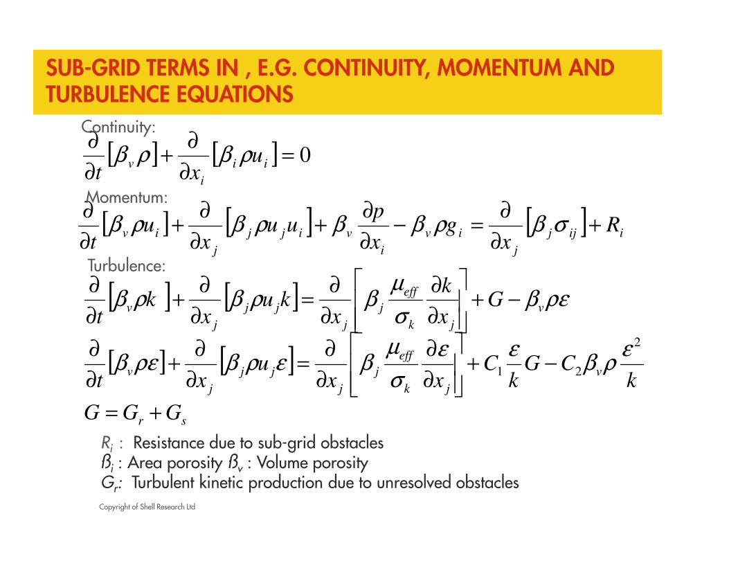
SUB-GRID TERMS IN , E.G. CONTINUITY, MOMENTUM AND TURBULENCE EQUATIONS
[ ] [ ] 0=∂
∂+
∂
∂ii
i
v uxt
ρβρβ
[ ] [ ] [ ]iijj
j
iv
i
vijj
j
iv Rx
gx
puu
xu
t+
∂
∂=−
∂
∂+
∂
∂+
∂
∂σβρββρβρβ
Ri : Resistance due to sub-grid obstaclesßi : Area porosity ßv : Volume porosityGr: Turbulent kinetic production due to unresolved obstacles
Continuity:
Momentum:
Turbulence:
[ ] [ ] ρεβσ
µβρβρβ v
jk
eff
j
j
jj
j
v Gx
k
xku
xk
t−+
∂
∂
∂
∂=
∂
∂+
∂
∂
[ ] [ ]k
CGk
Cxx
uxt
v
jk
eff
j
j
jj
j
v
2
21
ερβ
εε
σ
µβερβρεβ −+
∂
∂
∂
∂=
∂
∂+
∂
∂
sr GGG +=

Copyright of Shell Research Ltd
POROSITY/DISTRIBUTED RESISTANCE APPROACH
� Convert geometry to cell-wise values of:� Porosity (area and volume)
� (Tensor) drag
� Turbulence generation
9
Drag on log-scale.
(NB Small obstacles
omitted in picture)
�Real plant �CAD File �PDR Representation
CAD_PDR (Shell’s Internal Tool)
Copyright of Shell Research Ltd
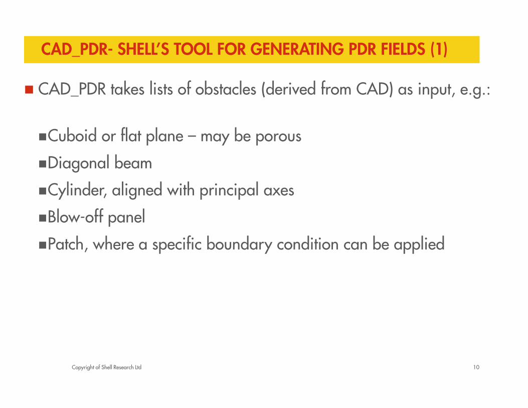
CAD_PDR- SHELL’S TOOL FOR GENERATING PDR FIELDS (1)
� CAD_PDR takes lists of obstacles (derived from CAD) as input, e.g.:
�Cuboid or flat plane – may be porous
�Diagonal beam
�Cylinder, aligned with principal axes
�Blow-off panel
�Patch, where a specific boundary condition can be applied
10

Copyright of Shell Research Ltd
CAD_PDR- SHELL’S TOOL FOR GENERATING PDR FIELDS (2)
� CAD_PDR calculates fields required by the PDR CFD model cell by cell on the mesh. For example:
� Area porosities in the mass and diffusion fluxes
� Volume porosities in appropriate source and transient terms
� Sub-grid obstacle resistance (drag tensor)source term in
momentum equations
� Sub-grid obstacle turbulence source term in k-epsilon equations
(with length scale related to obstacle diameter)
� Sub-grid flame area source term enhances combustion (in
addition to effect of turbulence increase).
11

Copyright of Shell Research Ltd
COMBUSTION MODEL � The combustion model (same
as available in OpenFoampackage XiFoam) solves a progress variable equation.
� The source term is closed using turbulent flame speed which is obtained by solving equations for the flame wrinkling factor.
� For the quasi-laminar flame propagation phase a simple model is used.
� Effects of compression is taken into account in laminar flame speed, unburnt gas density and unburnt thermal diffusivity.
Ξ: the ratio of the average flame surface area to the average flame area projected in the direction of mean flame propagation. This is the same as the local ratio of the turbulent and laminar flame speeds.
Ut, �����= � + ��;
R: is the flame radius

Copyright of Shell Research Ltd
SUBMODEL FOR FLAME WRINKLING FACTOR Ξ Ξ Ξ Ξ
Flame wrinkling factor Ξ is divided into contribution from turbulence ΞT and from sub grid objects ΞS.
This means that turbulent flame speed is calculated as follows:Ut = ΞT ΞS Sl.
A correlation for turbulent burning velocity based on recent data [Bradley et al. 2013], allowing for positive and negative Markstein numbers, and quench at high Karlowitz number is used to calculate flame wrinkling contribution from turbulence ΞT.
13November 2012

Copyright of Shell Research Ltd
STEPS IN EXPLOSION MODELLING USING CAD_PDR/PDRFOAM
Steps
� Mesh planes automatically fitted to large obstacles and
surfaces (PDRFitMesh)
� Program (CAD_PDR) to read CAD files (up to and derive
sub-grid parameters per computational cell
� Blocked cells removed from mesh (PDRMesh)
� Internal surfaces (baffles)
� CFD run (PDRFoam)

Copyright of Shell Research Ltd
EXPERIMENTAL VALIDATION– SMALL SCALE
15
� Validation test matrix
Case Fuels
Gaps Propane, Methane and Ethene
Solvex Propane and Methane
Merge Medium Propane, Methane and Ethene
Buxton S Series Propane, Methane, Ethene and Hydrogen
Gaps(Ergos) Propane, Methane,Ethene and Hydrogen

Copyright of Shell Research Ltd
RESULTS - SMALL SCALE VALIDATION – OVERPRESSURE
16
1
10
100
1000
10000
10 100 1000 10000
pre
dic
ted,
mb
measured, mb
Gaps
S-Series
Solvex
MergeMed
pred=meas
pred=1/2 obs
pred=2*obs

Copyright of Shell Research Ltd
EXPERIMENTAL VALIDATION – LARGE SCALE
17
� Validation test matrix
Case Fuel
CMI M24 Propane and Methane
BFETS Phase 2 JIP Narrow
Methane
BFETS Phase 2 JIP Wide
Methane
BFETS Phase 3 HSE Methane

Copyright of Shell Research Ltd
RESULTS - LARGE SCALE VALIDATION – MEDIAN OVERPRESSURE
18
10
100
1000
10000
100 1000 10000
pre
dic
ted,
mb
measured, mb
M24
BFETS JIP Wide
pred=meas
pred=1/2 obs
pred=2*obs
BFETS JIP HSE
BFETS JIP Narrow

Copyright of Shell Research Ltd 19November 2012
RESULTS - LARGE SCALE VALIDATION – OVERPRESSURE (1)
10
100
1000
10000
100 1000 10000
pre
dic
ted,
mb
measured, mb
BFETS JIP Wide 24
pred=meas
pred=1/2 obs
pred=2*obs
BFETS JIP Wide 25

Copyright of Shell Research Ltd 20November 2012
RESULTS - LARGE SCALE VALIDATION – OVERPRESSURE (2)
10
100
1000
100 1000
pre
dic
ted,
mb
measured, mb
BFETS JIP Wide 26
pred=meas
pred=1/2 obs
pred=2*obs
BFETS JIP Wide 27

Copyright of Shell Research Ltd
CONCLUSIONS
CAD_PDR/PDRFoam has the following features:
� Input from obstacle files, derived from CAD, with a range of obstacle types, including diagonal beams, allowing for intersecting obstacles.
� Use of the Weller’s combustion model and correlation for turbulent burning velocity based on recent data, allowing for positive and negative Markstein numbers, and quench at high Karlowitz number.
� Validation results against small scale and large scale experiments were performed using PDRFoam. Maximum overpressure, median of overpressure and maximum overpressure at each probe points are predicted within the accuracy of ± 50 % for four different fuels.

Copyright of Shell Research Ltd
OTHER FUNCTIONALITIES
22
� Efficient parallelization of the code� Non-orthogonal external mesh extending to infinity.� Auto fitting mesh planes to obstacle faces, fitting of the mesh to
large obstacles and to distant buildings.� Adaptive mesh refinement (AMR) to capture flame
propagation and pressure wave needed to accurately predict pressure decay.
� Flame quenching, advection of flame area and persistence of flame area generation outside congestion.
� Option to use different turbulence models for explosion analysis.

Copyright of Shell Research Ltd
FUTURE WORK
23
� Further validations against small scale experiments e.g. Solvex1/6, quarter box and large scale experiments (BFETS Phase 2 and Phase 3).
� Extension of the model for non-uniform gas clouds / fuel-air mixtures and subsequent validations against large scale BFETS Phase 3B experiments.
� Validation of the model for explosion mitigations i.e. to the cases where water deluge was used to mitigate explosion.
� Working on criteria to predict deflagration to detonation transition.
� Combine with OpenFOAM-based dispersion simulations to run ensemble simulations for probabilistic explosion assessment

Questions?