modelling and verification relay interlocking systems and verification of relay interlocking...
TRANSCRIPT

Modelling and Verificationof
Relay Interlocking Systems
Anne E. Haxthausen & Marie Le Bliguet & Andreas Andersen Kjær
Informatics and Mathematical ModellingTechnical University of Denmark
Modelling and VerificationofRelay Interlocking Systems – p. 1/30

Agenda
1. Project goal.
2. Informal description of the application domain.
3. Model of an interlocking system and its environment.
4. Safety properties and their verification.
5. Conclusions.
Modelling and VerificationofRelay Interlocking Systems – p. 2/30

Project background & goal
Project made for Banedanmark:
◆ Background: Banedanmark verifies relay interlocking systems bymanual inspection of circuit diagrams!
◆ Goal: to formalize and automate the verification process.
◆ Approach:
of interlocking system
of environment
safety conditions
behavioural model resultsstation documentationmodel check
RSL−SAL spec
w. SAL tool
behavioural model
◆ Status: This approach has been applied to Stenstrup station inDenmark.
Modelling and VerificationofRelay Interlocking Systems – p. 3/30
Agenda
1. Project goal.
2. Informal description of the application domain.
3. Model of an interlocking system and its environment.
4. Safety properties and their verification.
5. Conclusions.
Modelling and VerificationofRelay Interlocking Systems – p. 4/30
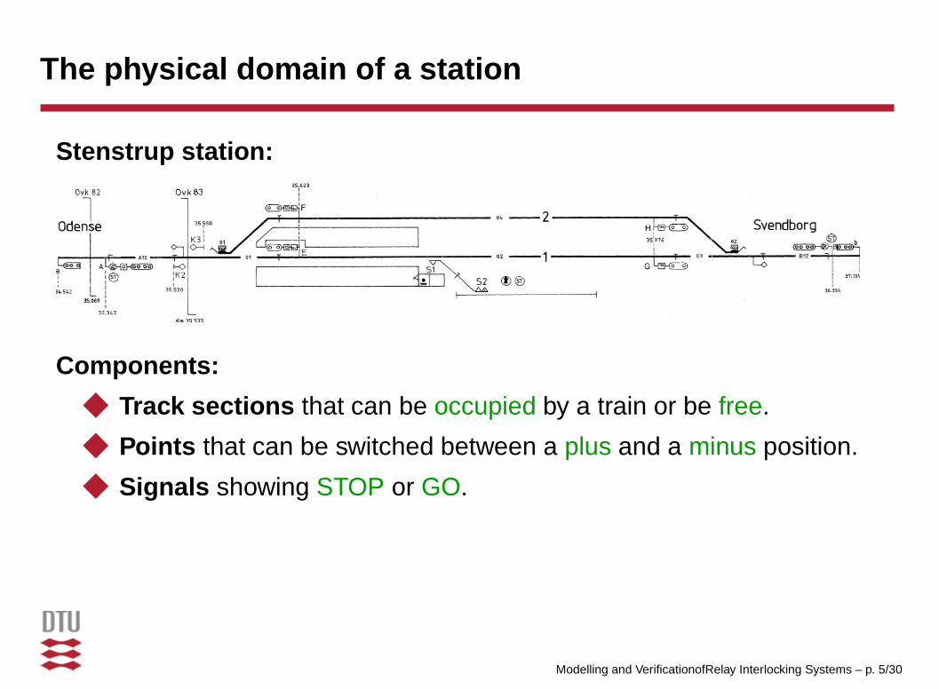
The physical domain of a station
Stenstrup station:
Components:
◆ Track sections that can be occupied by a train or be free.
◆ Points that can be switched between a plus and a minus position.
◆ Signals showing STOP or GO.
Modelling and VerificationofRelay Interlocking Systems – p. 5/30
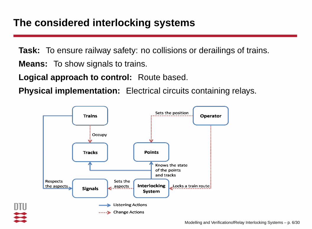
The considered interlocking systems
Task: To ensure railway safety: no collisions or derailings of trains.
Means: To show signals to trains.
Logical approach to control: Route based.
Physical implementation: Electrical circuits containing relays.
Modelling and VerificationofRelay Interlocking Systems – p. 6/30
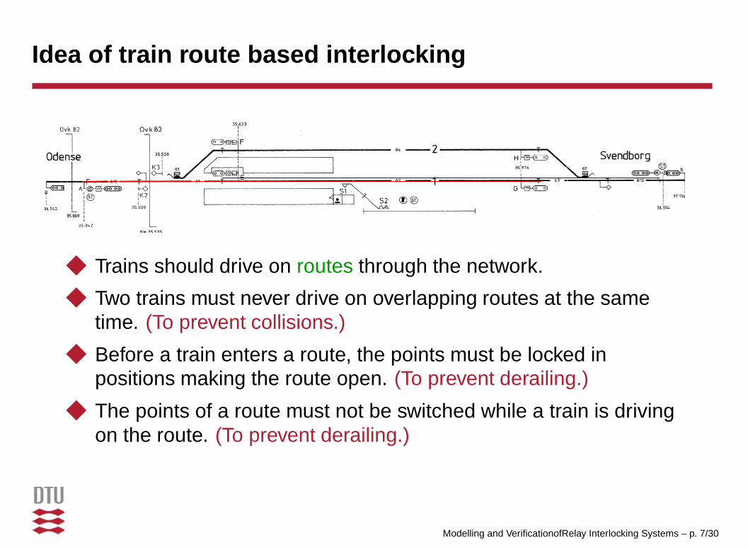
Idea of train route based interlocking
◆ Trains should drive on routes through the network.
◆ Two trains must never drive on overlapping routes at the sametime. (To prevent collisions.)
◆ Before a train enters a route, the points must be locked inpositions making the route open. (To prevent derailing.)
◆ The points of a route must not be switched while a train is drivingon the route. (To prevent derailing.)
Modelling and VerificationofRelay Interlocking Systems – p. 7/30

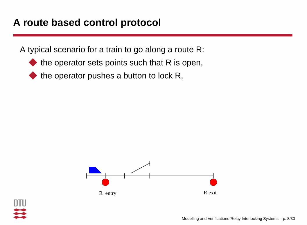
A route based control protocol
A typical scenario for a train to go along a route R:
◆ the operator sets points such that R is open,
R entry R exit
Modelling and VerificationofRelay Interlocking Systems – p. 8/30
A route based control protocol
A typical scenario for a train to go along a route R:
◆ the operator sets points such that R is open,
◆ the operator pushes a button to lock R,
R entry R exit
Modelling and VerificationofRelay Interlocking Systems – p. 8/30

A route based control protocol
A typical scenario for a train to go along a route R:
◆ the operator sets points such that R is open,
◆ the operator pushes a button to lock R,
◆ the system locks R (as no conflicting routes are locked),
◆ the system sets entry signal to GO (as R is empty and locked),
◆ the system detects when the train enters the route,
◆ the system sets entry signal to STOP,
R entry R exit
Modelling and VerificationofRelay Interlocking Systems – p. 8/30
A route based control protocol
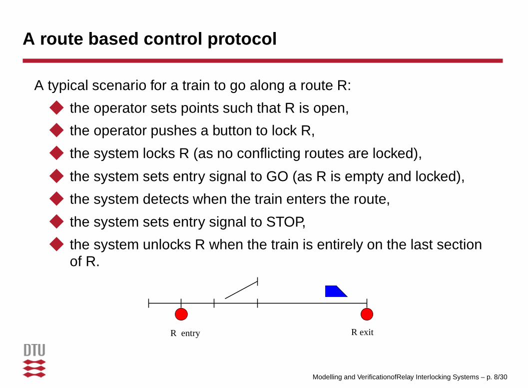
A typical scenario for a train to go along a route R:
◆ the operator sets points such that R is open,
◆ the operator pushes a button to lock R,
◆ the system locks R (as no conflicting routes are locked),
◆ the system sets entry signal to GO (as R is empty and locked),
◆ the system detects when the train enters the route,
◆ the system sets entry signal to STOP,
◆ the system unlocks R when the train is entirely on the last sectionof R.
R entry R exit
Modelling and VerificationofRelay Interlocking Systems – p. 8/30
Relay circuits
consist of◆ power supply
◆ wires◆ relays
■ external relays: captor the state of track sections and points■ internal relays: captor control state, e.g. route lockings■ 2 states: drawn (↑) or dropped(↓)
◆ contacts■ ruled by relays■ 2 states: connected ordis-connected
◆ buttons■ controlled by the operator■ 2 states: pushed or released
◆ lamps, ...
Modelling and VerificationofRelay Interlocking Systems – p. 9/30
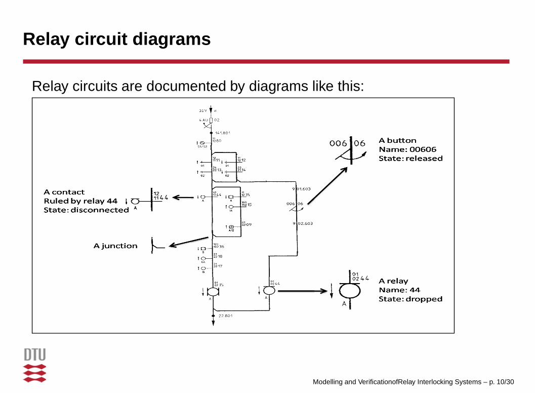
Relay circuit diagrams
Relay circuits are documented by diagrams like this:
Modelling and VerificationofRelay Interlocking Systems – p. 10/30
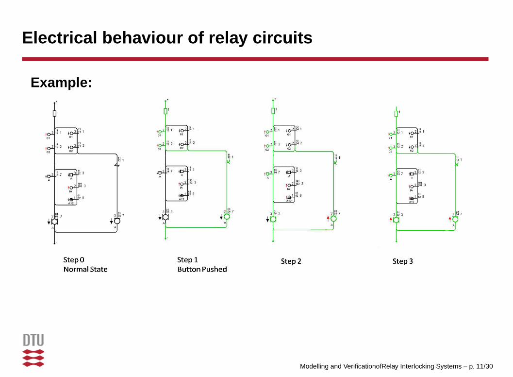
Electrical behaviour of relay circuits
Example:
Modelling and VerificationofRelay Interlocking Systems – p. 11/30
Agenda
1. Project goal.
2. Informal description of the application domain.
3. Model of an interlocking system and its environment.
4. Safety properties and their verification.
5. Conclusions.
Modelling and VerificationofRelay Interlocking Systems – p. 12/30
Model: state space
◆ b : Bool for each button b■ true means conductive (pushed)■ Initial state: false (released)
◆ r : Bool for each relay r■ true means drawn (↑)■ Initial state: indicated on diagrams
◆ state of contacts can be derived from the state of their relay
Modelling and VerificationofRelay Interlocking Systems – p. 13/30

Model: transition rules for internal relays
For each internal relay r:[draw r ] ∼r ∧ currentThrough r → r′ = true,[drop r ] r ∧ ∼ currentThrough r → r′ = false
currentThrough r: condition for current to go through r.
Modelling and VerificationofRelay Interlocking Systems – p. 14/30
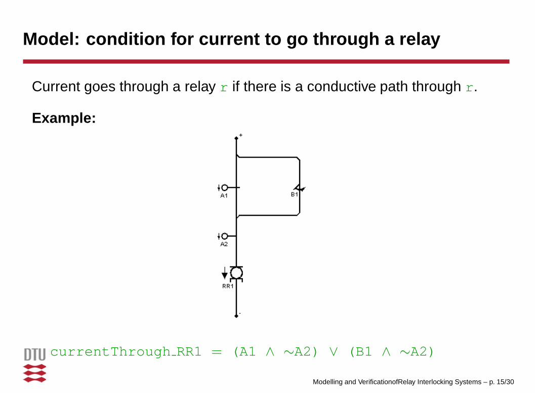
Model: condition for current to go through a relay
Current goes through a relay r if there is a conductive path through r.
Example:
currentThrough RR1 = (A1 ∧ ∼A2) ∨ (B1 ∧ ∼A2)
Modelling and VerificationofRelay Interlocking Systems – p. 15/30
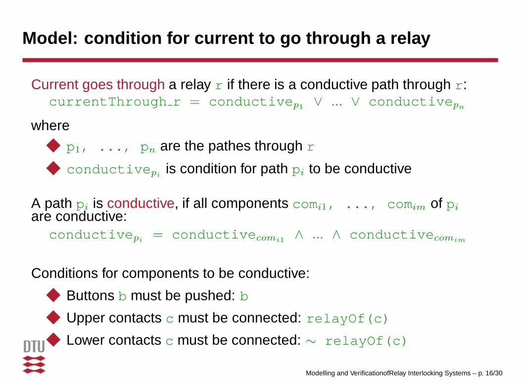
Model: condition for current to go through a relay
Current goes through a relay r if there is a conductive path through r:currentThrough r = conductivep1
∨ ... ∨ conductivepn
where◆ p1, ..., pn are the pathes through r
◆ conductivepiis condition for path pi to be conductive
A path pi is conductive, if all components comi1, ..., comim of pi
are conductive:conductivepi
= conductivecomi1∧ ... ∧ conductivecomim
Conditions for components to be conductive:
◆ Buttons b must be pushed: b
◆ Upper contacts c must be connected: relayOf(c)
◆ Lower contacts c must be connected: ∼ relayOf(c)
Modelling and VerificationofRelay Interlocking Systems – p. 16/30

Modelling the environment
External events:◆ A button B is being pushed or released.
◆ A track section T is being occupied or freed. This is detected byan external relay T being released or drawn.
◆ A point P changes position. This is detected by two externalrelays, P+ and P-, associated with the point.
Model assumptions:
◆ External events can only happen when no internal event ispossible.
idle idle idle
external event internal event busy state
Modelling and VerificationofRelay Interlocking Systems – p. 17/30
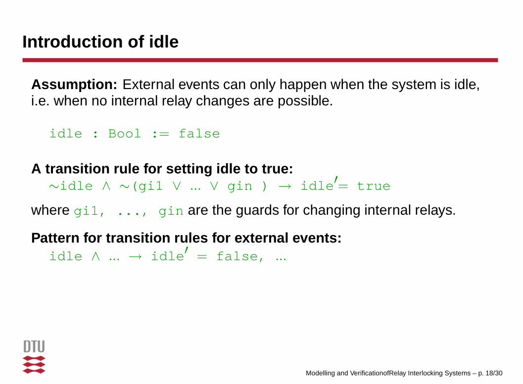
Introduction of idle
Assumption: External events can only happen when the system is idle,i.e. when no internal relay changes are possible.
idle : Bool := false
A transition rule for setting idle to true:∼idle ∧ ∼(gi1 ∨ ... ∨ gin ) → idle′= true
where gi1, ..., gin are the guards for changing internal relays.
Pattern for transition rules for external events:idle ∧ ... → idle′ = false, ...
Modelling and VerificationofRelay Interlocking Systems – p. 18/30

Rules for track relays
Two models:◆ Random track behaviour: Track sections T can be occupied and
freed randomly:[T ] idle → idle′ = false, T′ = ∼T
◆ Ordered track behaviour: Only track events reflecting movementsfor trains that
■ do not pass signals showing STOP■ do not change direction while using a route■ do not split■ only enter the station from entry sections■ only leaves the staion at exit sections
Requires additional state variables.
Modelling and VerificationofRelay Interlocking Systems – p. 19/30

Rules for points
Four transition rules for each point P:
[plusToIntermediate ]idle ∧ P+ ∧ unlockedP ∧ tP →
idle′ = false, P+′ = false
[IntermediateToMinus ] ...[minusToIntermediate ] ...[IntermediateToPlus ] ...
where P+ is true only when P is in plus position, unlockedP is truewhen P is unlocked, tP is true when P is free.
Modelling and VerificationofRelay Interlocking Systems – p. 20/30
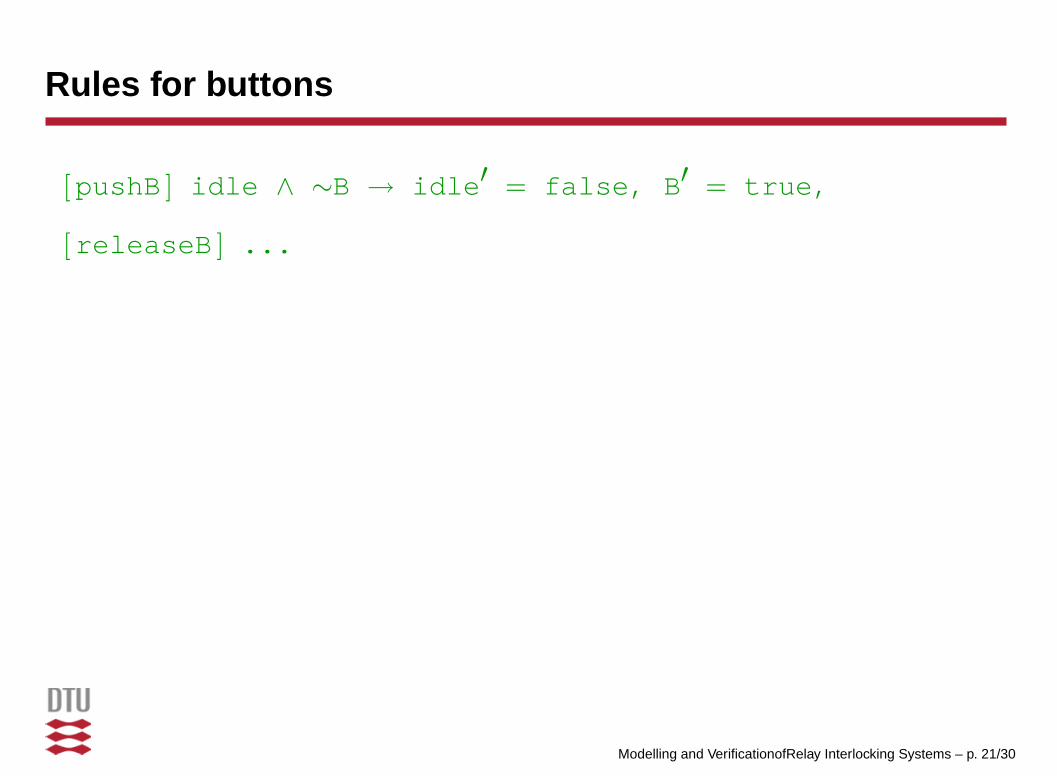
Rules for buttons
[pushB ] idle ∧ ∼B → idle′ = false, B′ = true,
[releaseB ] ...
Modelling and VerificationofRelay Interlocking Systems – p. 21/30
Agenda
1. Project goal.
2. Informal description of the application domain.
3. Model of an interlocking system and its environment.
4. Safety properties and their verification.
5. Conclusions.
Modelling and VerificationofRelay Interlocking Systems – p. 22/30

Proof obligations
◆ Safety conditions at two levels of abstraction:■ Implementation independent level: general safety conditions■ Implementation level: conditions derived from train route
tables – requirements in train route based interlocking
◆ Confidence conditions
Modelling and VerificationofRelay Interlocking Systems – p. 23/30

Requirements in train route based interlocking
1. Two conflicting train routes must not be locked at the same time.
2. When a route is locked, the points must be in positions making theroute open.
3. When a route is locked, it must retain being locked until the lastsection of the route is occupied.
4. When a route entrance signal shows GO, the route must belocked and empty, and certain other signals must show STOP.This implies that when a train enters a route, the signal mustchange to STOP.
Modelling and VerificationofRelay Interlocking Systems – p. 24/30
Conditions derived from a train route table
For a specific station, the requirements for train route based interlockingcan be instantiated with data from its train route table and expressed asLTL assertions.
Example: Conflicting routes 1 and 7 for Stenstrup must not be locked atthe same time:
G(r1 ∨ r7),
where ri = true when route i is unlocked.
For Stenstrup station, 24 such assertions have been proved for randomtrack behaviour.
Modelling and VerificationofRelay Interlocking Systems – p. 25/30

General safety conditions
◆ No derailing at any point P:■ When P is occupied, P is in + or - position:
t tP t+
t-
G(∼tP ⇒ (P+ ∨ P−))
■ When a train is entering P from a +/- branch, P is in the rightposition:
t tP t+
t-
G(∼tP ∧ ∼t+ ⇒ P+)G(∼tP ∧ ∼t− ⇒ P−)
◆ No collisions: ...
For Stenstrup station, 12 general safety conditions have been proved forordered track behaviour.
Modelling and VerificationofRelay Interlocking Systems – p. 26/30

Confidence conditions
For Stenstrup station, 100 confidence conditions have been proved.
No internal events are possible in the initial state: X(idle)
No internal cycles: G(F(idle))
No critical races between internal events:The order of internal relay events does not alter the eventual state.
◆ Does the model include the states that can be obtained by changing relaysconcurrently?
◆ Will different interleavings give the same terminal state?
Two confidence conditions for each relay R:
G(canDrawR ⇒ X(∼canDrawR ⇒ R))
G(canDropR ⇒ X(∼canDropR ⇒ ∼R))
If a guard is true at one point, it remains true until the transition is taken.
Modelling and VerificationofRelay Interlocking Systems – p. 27/30

Experiments with Stenstrup Station
◆ Stenstrup Station and its interlocking system:■ 8 track sections, 2 points, 6 signals, 8 train routes.■ 4 buttons.■ 46 internal + 10 external relays.■ 18 diagrams.
◆ Transition system:■ 61 + x Boolean variables.■ 92 rules for internal relays.■ additional rules for buttons and external relays.
◆ Assertions:■ 100 confidence conditions.■ 24 conditions derived from the train route table.■ 12 general safety conditions.
◆ Results: All assertions are valid.
Modelling and VerificationofRelay Interlocking Systems – p. 28/30

Agenda
1. Project goal.
2. Informal description of the application domain.
3. Model of an interlocking system and its environment.
4. Safety properties and their verification.
5. Conclusions.
Modelling and VerificationofRelay Interlocking Systems – p. 29/30

Conclusions
Results:
◆ A method for extracting a behavioural model and safetyconditions from the station documentation.
◆ The method applied to Stenstrup station.◆ Under the assumptions made, we can conclude that
Stenstrup station is safe.
Future work:
◆ Scalability study.◆ Other ways of modelling / further inspection of assumptions.◆ Tools for automatic generation of model and assertions from
station documentation.
Modelling and VerificationofRelay Interlocking Systems – p. 30/30