modeling tool performance and interaction with other tools
TRANSCRIPT
Oil & Gas
Modeling tool performance and interaction with other tools in the BHABy Rick Young, Nikolos Manesh, Drilling International Juan Lopez de Alda and Hemanth Kolera, MSC Software
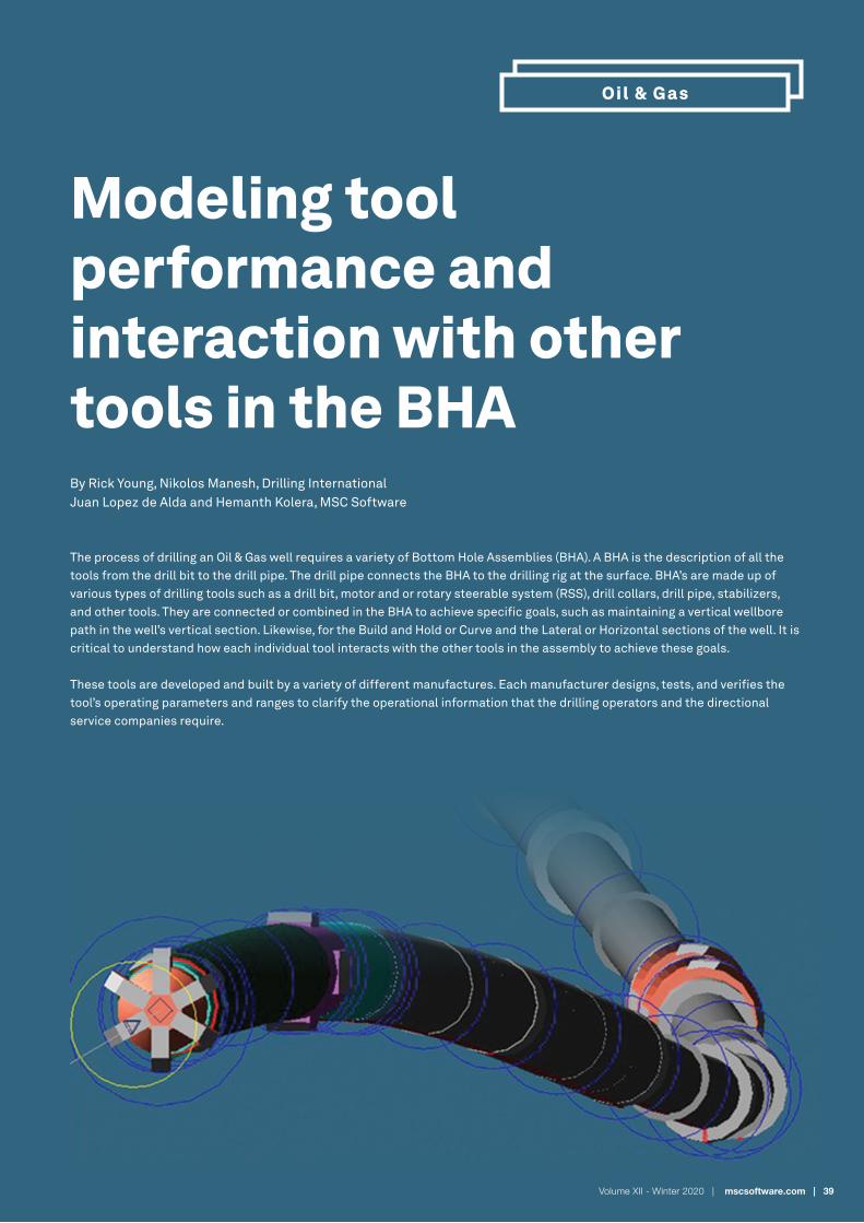
The process of drilling an Oil & Gas well requires a variety of Bottom Hole Assemblies (BHA). A BHA is the description of all the tools from the drill bit to the drill pipe. The drill pipe connects the BHA to the drilling rig at the surface. BHA’s are made up of various types of drilling tools such as a drill bit, motor and or rotary steerable system (RSS), drill collars, drill pipe, stabilizers, and other tools. They are connected or combined in the BHA to achieve specific goals, such as maintaining a vertical wellbore path in the well’s vertical section. Likewise, for the Build and Hold or Curve and the Lateral or Horizontal sections of the well. It is critical to understand how each individual tool interacts with the other tools in the assembly to achieve these goals.
These tools are developed and built by a variety of different manufactures. Each manufacturer designs, tests, and verifies the tool’s operating parameters and ranges to clarify the operational information that the drilling operators and the directional service companies require.
Volume XII - Winter 2020 | mscsoftware.com | 39

40 | Engineering Reality Magazine
Manufacturers test their tools in several ways. The first approach is to test them in their facility and determine their operating limits and specifications. Initially, the tool is run until it fails, and this is done several times. This approach can be expensive and doesn’t capture how the tool will interact with the other tools that are part of the BHA and operating in a well in real-time. Thereafter, the tools are tested in a test rig within a typical BHA that it will be run on. The limitation of this type of testing is that the tool is only being tested in the formations and drilling environment of a particular test site. Finally, the manufacturers may request that an operator test on a well that is currently being drilled. If the tool does not fail, then that indicates a successful test and a capable design. However if the tool fails, it could be expensive to trip the tool or lay it down. This could also potentially raise concerns about the new tool’s viability in the customer’s eyes.
1. Does the DnR create vibration that would be seen in the Bottom Hole Assembly (BHA)?
2. What is the best location to place the DnR on the string?
3. Does the DnR interfere with drill string oscillation tools?
4. How does placement impact bending moment of DnR?
A couple of validated wells from an operator were used for this purpose. Each well had been calibrated at a specific depth, matching high frequency downhole data at locations where high frequency instrument subs were placed (above the bit, above the BHA, and an instrument or two in the drill string above if available). The model was then run analytically at a different depth with the calibrated parameters to match the same instrument readings at that new depth.
Furthermore, tool manufacturers are not able to test their tools in extreme operating conditions that could be caused by multiple reasons such as
• Operational error. • Effect of other BHA tools that have degraded.• Severe dysfunctions of their tools and others in the BHA.• Effects of sudden changes in control inputs.
These reasons pose a specific problem for tool manufacturers on how a particular tool can be thoroughly tested, considering the following operating factors
• Operating range of the tool.• Effect of another tool degradation.• Interaction with other tools in the BHA.• Different formations and transitions.• Effect of dysfunctions at other depths and lengths of the drill string.
One possible solution to this question is to conduct a series of analytical studies to test the specific tool within a specific process. The process involves-
• Calibrated/Validated wells.• Specific BHAs.• Specific Formations and Depths.• Selected Operating Parameters, including controls and setpoints.
Alternative approach
An alternative approach is to use a fully non-linear analytical drilling tool. One such tool is Adams Drill, from the MSC Software portfolio. Adams Drill was developed to predict the dynamic behavior of a drill string, including any non-linear and fully coupled axial, lateral, and torsional responses to various sequences of surface control parameters. It enables engineers to determine forces and motions at every location along the drill string in user-defined engineering units.
In this study, Adams Drill was used to model the performance of an eccentric, wellbore conditioning tool called Drill-N-Ream (DnR). The DnR is an eccentric tool that scraps the well bore’s rim to condition or remove ledges that would hinder the drill string’s movement. The main customer concern is about the vibration levels that it may create and the potential interference with other tools in the BHA. If there are high vibration levels, the DnR is placed farther up the drill string.
There were four questions that this study hopes to answer:

Volume XII - Winter 2020 | mscsoftware.com | 41
Two different BHA configurations were used to study the interaction with other tools. Both DnR’s had different outside diameters and each of them was studied for the following Outer Diameters:
• Nominal outside diameters (6.75” and 8.5”)• Nominal plus 1/16”, 1/8” and 1/4” over the size of the hole.
In each well that was studied, the DnR tool was placed at five different locations on the drill string. Results were compared against the original calibration and validations for each well.
Studies and results:
The first Lateral Well had an Agitator, and one of the objectives of the study was to see the effect that the Agitator had on the DnR and vice versa. The Agitator is used to reduce friction and provides improved weight transfer
Well 1The specifications of this well are as follows. 10,168 ft deep well, with five different placements on the string and was compared to the same well without a DnR:
• Between Drill Collars• Between Cross Over and Drill Pipe• In the first Drilling Pipe set 90 ft behind Drill Collar• In the second Drilling Pipe set, 500 ft behind Drill Collar• In the Second Drilling Pipe set, 1000 ft behind Drill Collar• No Reamer
Figure 1: Well 1 Lateral Bit RPM – Omega Z, All Placements
Table 1: Well 1 Lateral StatisticsFigure 2: Well 2 Lateral Various DnR Placements and Sizes- Torsional Harmonics
The second lateral well was deeper and did not have an Agitator.
Well 210,275 ft deep well, with five different placements on the string and, was compared to the same well without a DnR:
• Between Drill Collars• Behind Upper Collar• In the first Drilling Pipe set 90 ft behind Drill Collar• In the second Drilling Pipe set, 500 ft behind Drill Collar• In the Second Drilling Pipe set, 1000 ft behind Drill Collar• No Reamer
Results obtain from the studies clearly show the following-
Well 1: The effect of the Agitator on the responses of the BHA tools is not affected by the Drill-N-Reamer interaction with the formation.
Figure 1 is a visual representation of Table 1. Table 1 shows that the DnR does not interfere with the Agitator since the bit RPM standard deviation at various placements of the DnR is not significantly higher than that of the ‘No DnR’ case.
Well2: Without an Agitator, there is an increased stick-slip response at the instruments in some of the studied placements, but there are two placements where there is no stick-slip phenomena, and one in particular shows very little effect on the instrument responses. That placement is number 3 (P3), set 90 feet behind the last Drill Collar.

Table 2: Statistics for Well 2 Lateral - Torsional Harmonics
Figure 3: Well 2 Lateral Various DnR Placements and Sizes – Bending Moments
Table 3: Statistics for Well 2 Lateral - Bending Moments
Figure 2 is a visual representation of Table 2. Table 2 shows the placement three (P3) is the best placement for the DnR. The others show higher RPM fluctuations with placement four (P4) and five (P5) significantly higher, at 107% and 112%, respectively. Table 2 also shows that placement three (P3) is similar in RPM fluctuation, so it can be inferred that it does not contribute to BHA vibrations.
Figure 3 is a visual representation of Table 3. Table 3 shows the placement three (P3) is the best placement for the DnR. The others show higher Bending Moments on the tool, with placement one (P1) and two (P2) significantly higher, 386% and 450%, respectively.
All plots for Axial Load, WOB, RPM, Twisting Moment, Torque, Bending Moment, Radial, Lateral displacements and velocities, etc. were reviewed and compared during the study.
Conclusions
The study shows that the interaction of Drill-N-Ream with other tools is critical and needs to be studied further.
The following were the key simulation findings-
1. The Drill-N-Ream did not create vibrations that can be seen in the BHA.
2. The optimum placement for the Drill-N-Ream was 90 feet above the BHA and resulted in the lowest torsional harmonics and the lowest bending moments.
3. The Drill-N-Ream did not interfere with drill string oscillation tools.
The study highlighted that placing the Drill-N-Ream further up the drill string causes stick-slip in the drill string. Stick-Slip is a drilling dysfunction that creates excess vibration throughout the drill string and hinders drilling performance.
Additional studies of different BHA configurations will have to be done to determine if there is any interaction between those configurations and the Drill-N-Ream tool. Future studies can be also be done to cover formation and operational changes, degradation of tools, and existing dysfunctions.
42 | Engineering Reality Magazine