modeling software with uml
TRANSCRIPT


Index

Purpose of UML
• UML = Unified Modeling Language (http://www.uml.org)
• UML provides a standard way for representing software systems. It brings a common point of reference for establishing a discussion among the different stakeholders of a software project.
• UML is used to support a software development process, e.g., the Rational Unified Process (RUP).
• UML has been associated with the analysis of requirements. In agile methodologies it serves as a tool for speeding up the discussion. Creating and maintaining UML diagrams is not the purpose. “Their emphasis is on selective communication rather than complete specification.” Martin Fowler (http://martinfowler.com/bliki/UmlAsSketch.html). [1] Chapter 2.

UML diagrams overview
• Structural modeling diagrams: define the static architecture of a model.• Class diagram• Object diagram• Package diagram• Component diagram• Composite diagram• Deployment diagram
• Behavioral modeling diagrams: define the interaction among the elements within a model.• Use case diagram• Activity diagram• Sequence diagram• Communication diagram• State machine diagram• Timing diagram• Interaction overview diagram

UML diagrams overview
UML diagram taxonomy. Source [1]
Structural modeling diagrams
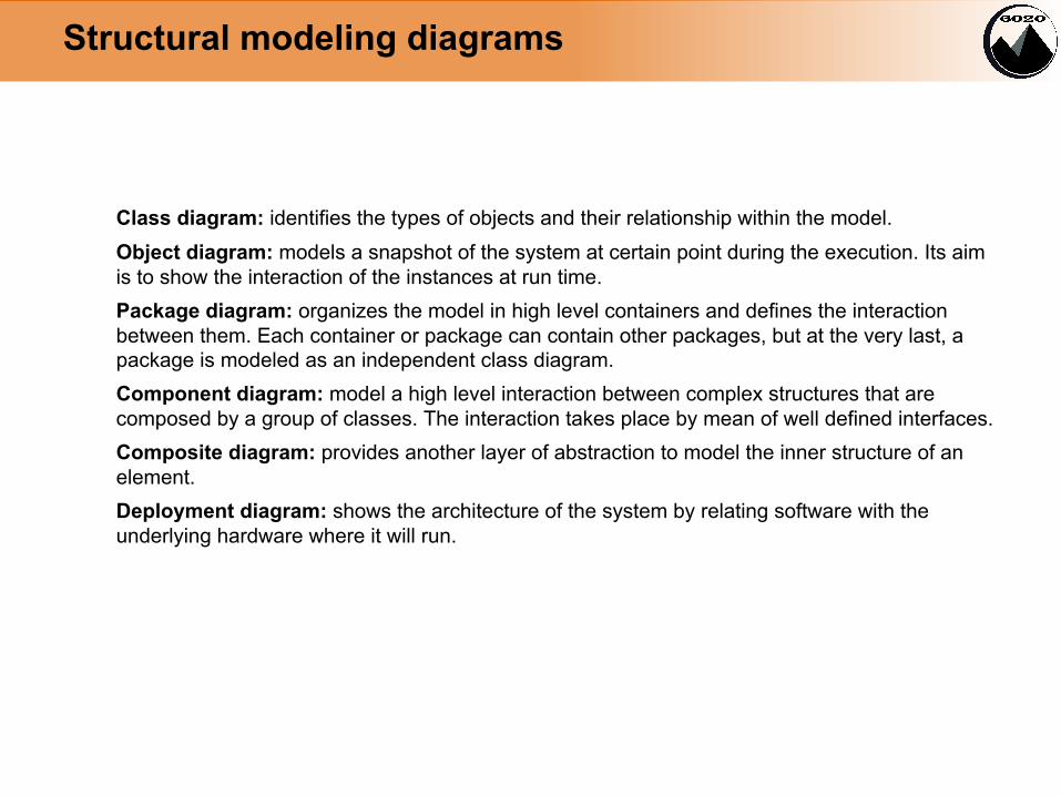
Class diagram: identifies the types of objects and their relationship within the model.Object diagram: models a snapshot of the system at certain point during the execution. Its aim is to show the interaction of the instances at run time. Package diagram: organizes the model in high level containers and defines the interaction between them. Each container or package can contain other packages, but at the very last, a package is modeled as an independent class diagram.Component diagram: model a high level interaction between complex structures that are composed by a group of classes. The interaction takes place by mean of well defined interfaces.Composite diagram: provides another layer of abstraction to model the inner structure of an element.Deployment diagram: shows the architecture of the system by relating software with the underlying hardware where it will run.

Behavioral modeling diagrams
Use case diagram: models the interaction between the user and the system. This diagram is the entry point to define the functionality of the software that needs to be build.Activity diagram: is used to model processes and workflows.Sequence diagram: shows the exchange of messages along the time among objects of the model.Communication diagram: similar to sequence diagrams without using a timeline. This diagram models the interaction of objects remarking the order in which the message exchange happens.State machine diagram: models the execution of a system by representing the different states and the path to reach them.Timing diagram: mixes sequence and state diagrams. They are used when we need to associate time restrictions to the different state. This diagram is quite used in electronic engineering.Interaction overview diagram: mixes activity and sequence diagrams. It is basically an activity diagram where each activity is detailed as a sequence diagram.
Use cases
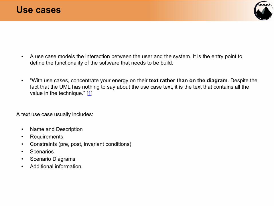
• A use case models the interaction between the user and the system. It is the entry point to define the functionality of the software that needs to be build.
• “With use cases, concentrate your energy on their text rather than on the diagram. Despite the fact that the UML has nothing to say about the use case text, it is the text that contains all the value in the technique.” [1]
A text use case usually includes:
• Name and Description• Requirements• Constraints (pre, post, invariant conditions)• Scenarios• Scenario Diagrams• Additional information.

Use cases
Actor: an agent that interacts with the system. It can be a person or another system.
Use case: represents a piece of behavior of the system from an external point of view.
Relationships• <<include>>: to represent a use case that is always executed as part of a bigger use case.• <<extend>>: to represent the variation of a use case under exceptional circumstances.

UML in practice
• The main idea is to use UML as a vehicle to implement good code.• Going from an initial idea to working software involves a refinement process to understand the
details of the potential solution.• Our suggested process starts by defining the functionality of the system to build relying on use
case diagrams. This will give us a good overview from the user perspective.• Each use case will be refined by using different sequence diagrams. This will make us see
scenarios that we did not contemplate.• The sequence diagram will give us a first hint of the needed entities that interact within certain
scenario. These entities can be modelled using an OO approach within a class diagram.• Finally, the class diagram can be translated to the selected programming language.• The process repeats until we reach a level that satisfies our expected solution.

UML in practice
Let’s see how to put this in practice with the following problem:
Implement the software control of an ATM machine for withdrawing cash.
As already said, we will work in the following order:1. Use case diagram2. Sequence diagram3. Class diagram4. Code
In the following we show one iteration of our process (code not included)
UML in practice
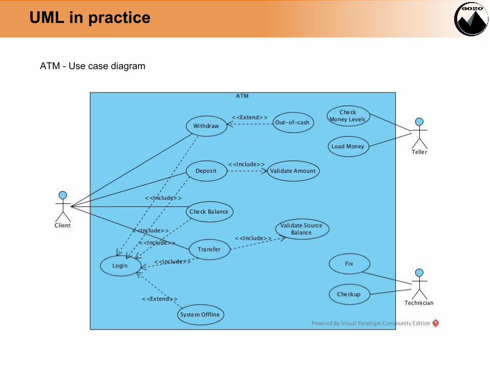
ATM - Use case diagram

UML in practice
ATM - Sequence diagram:Withdraw use caseSuccessful scenario
UML in practice
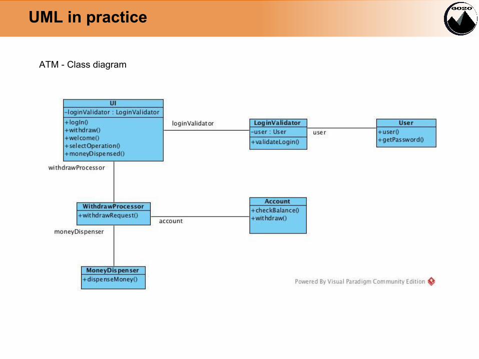
ATM - Class diagram

Wrapping up
• UML is a mean not a purpose. Use it for speeding up your development.• You might start coding directly because you know the solution quite clear, but maybe your team
does not.• UML can serve as documentation. Keep your diagrams for future discussions or even for
refreshing your memory.• Remember our refining process and take into account that you can jump between diagrams /
code in any way that best suits you. The following is just a suggestion:

References
Books1. UML distilled: a brief guide to the standard object modeling language (3rd edition). Martin
Fowler.2. Writing effective Use Cases. Alistair Cockburn.
CASE Tools1. Visual Paradigm2. Enterprise Architect3. ArgoUML
Other references1. UML 2.0 online tutorial by the University of Girona2. http://www.uml-diagrams.org/