modeling, simulation and synthesis in an embedded...
TRANSCRIPT

Center for Embedded Computer SystemsUniversity of California, Irvine
Modeling, Simulation and Synthesis in anEmbedded Software Design Flow for an ARM Processor
Gunar Schirner, Gautam Sachdeva, Andreas Gerstlauer, Rainer Domer
Technical Report CECS-06-06May 25, 2006
Center for Embedded Computer SystemsUniversity of California, IrvineIrvine, CA 92697-2625, USA
(949) 824-8059
{hschirne, gsachdev, gerstl, doemer}@uci.eduhttp://www.cecs.uci.edu/
Modeling, Simulation and Synthesis in anEmbedded Software Design Flow for an ARM Processor
Gunar Schirner, Gautam Sachdeva, Andreas Gerstlauer, Rainer Domer
Technical Report CECS-06-06April 10, 2006
Center for Embedded Computer SystemsUniversity of California, IrvineIrvine, CA 92697-3425, USA
(949) 824-8059
{hschirne, gsachdev, gerstl, doemer}@uci.eduhttp://www.cecs.uci.edu
AbstractSystem level design is one approach to tackle the complexity of designing a modern System-on-Chip. One
major aspect is the capability of developing the system model irrespectable of the later occurring hardwaresoftware split, with the goal to develop both hardware and software seamlessly at the same time and to mergethe traditionally separated development flows.
Hardware/software co-simulation is needed for an efficiently integrated design flow. Depending on the designphase, this co-simulation can be performed at different levels of abstraction. Early in the design phase, a a veryabstract simulation at the unpartitioned specification level yields fast functional results. On the other end, thecycle accurate simulation of RTL hardware and instruction set simulated software allows an accurate insight tothe final system performance.
This report focuses on the software perspective of a co-design/co-simulation environment. In form of a casestudy, we address three major tasks necessary to build an integrated embedded software design flow: modelingof a processor core (including an instruction set simulator), porting of a RTOS to the selected processor core,and the embedded software generation that includes RTOS targeting of the generated code.
In particular, we have modeled a popular ARM core, the ARM7TDMI, at an abstract level, as well as ona cycle-accurate level using SWARM, an Instruction Set Simulator (ISS) for the ARM core. Furthermore, wehave ported MicroC/OS-II, a Real-Time Operating System (RTOS), to run on top of the SWARM ISS. Finally, weimplemented a software generation tool. It automatically synthesizes C code, targeted to the selected Real-TimeOperating System (RTOS), from the refined design captured in the a system level design language.
We demonstrate our embedded software development flow by use of an automotive application. An example ofanti-lock breaks uses a distributed architecture of sensors and actuators connected via a Controller Area Network(CAN). We undergo all steps of the design flow starting with the capturing of the specification model, down tovalidation of the implementation with an ISS based co-simulation. Our results show that the co-design/co-simulation environment is feasible. All refined models, including the ISS based cycle-accurate model, show afunctional correct behavior.

Contents1 Introduction 2
1.1 Problem Statement . . . . . . . . . . . . . . . . . . . . . . . . . . . . . . . . . . . . . . . . . 31.2 Related Work . . . . . . . . . . . . . . . . . . . . . . . . . . . . . . . . . . . . . . . . . . . . 31.3 Outline . . . . . . . . . . . . . . . . . . . . . . . . . . . . . . . . . . . . . . . . . . . . . . . 4
2 Processor 42.1 ARM7TDMI . . . . . . . . . . . . . . . . . . . . . . . . . . . . . . . . . . . . . . . . . . . . 4
2.1.1 Instruction Pipeline . . . . . . . . . . . . . . . . . . . . . . . . . . . . . . . . . . . . . 42.1.2 Architecture . . . . . . . . . . . . . . . . . . . . . . . . . . . . . . . . . . . . . . . . . 52.1.3 Bus Architecture . . . . . . . . . . . . . . . . . . . . . . . . . . . . . . . . . . . . . . 5
2.2 Abstract Processor Modeling . . . . . . . . . . . . . . . . . . . . . . . . . . . . . . . . . . . . 62.2.1 Behavioral Model . . . . . . . . . . . . . . . . . . . . . . . . . . . . . . . . . . . . . . 62.2.2 OS Model . . . . . . . . . . . . . . . . . . . . . . . . . . . . . . . . . . . . . . . . . . 72.2.3 Bus Functional Model . . . . . . . . . . . . . . . . . . . . . . . . . . . . . . . . . . . 7
2.3 Cycle-Accurate Instruction Set Simulator . . . . . . . . . . . . . . . . . . . . . . . . . . . . . 92.3.1 Selection of an ISS . . . . . . . . . . . . . . . . . . . . . . . . . . . . . . . . . . . . . 92.3.2 SWARM (Software ARM) . . . . . . . . . . . . . . . . . . . . . . . . . . . . . . . . . 102.3.3 Cycle-Accurate PE Model . . . . . . . . . . . . . . . . . . . . . . . . . . . . . . . . . 12
3 Real-Time Operating System 133.1 RTOS Selection . . . . . . . . . . . . . . . . . . . . . . . . . . . . . . . . . . . . . . . . . . . 133.2 MicroC/OS-II . . . . . . . . . . . . . . . . . . . . . . . . . . . . . . . . . . . . . . . . . . . . 14
3.2.1 MicroC/OS-II Structure . . . . . . . . . . . . . . . . . . . . . . . . . . . . . . . . . . 153.2.2 Kernel and Kernel Services . . . . . . . . . . . . . . . . . . . . . . . . . . . . . . . . . 163.2.3 Adapting MicroC/OS-II for an ARM core . . . . . . . . . . . . . . . . . . . . . . . . . 163.2.4 Interrupt Handling and Timer Integration . . . . . . . . . . . . . . . . . . . . . . . . . 17
4 Embedded Software Generation 184.1 Scheduling Refinement . . . . . . . . . . . . . . . . . . . . . . . . . . . . . . . . . . . . . . . 194.2 Embedded Software Generation and RTOS Targeting . . . . . . . . . . . . . . . . . . . . . . . 19
5 Experiments 205.1 Example Application . . . . . . . . . . . . . . . . . . . . . . . . . . . . . . . . . . . . . . . . 205.2 Refinement . . . . . . . . . . . . . . . . . . . . . . . . . . . . . . . . . . . . . . . . . . . . . 205.3 Results . . . . . . . . . . . . . . . . . . . . . . . . . . . . . . . . . . . . . . . . . . . . . . . . 21
6 Conclusions 21
References 22
i

List of Figures1 Software synthesis. . . . . . . . . . . . . . . . . . . . . . . . . . . . . . . . . . . . . . . . . . 32 ARM7TDMI instruction pipeline . . . . . . . . . . . . . . . . . . . . . . . . . . . . . . . . . . 43 ARM7TDMI processor core . . . . . . . . . . . . . . . . . . . . . . . . . . . . . . . . . . . . 54 AMBA bus architecture . . . . . . . . . . . . . . . . . . . . . . . . . . . . . . . . . . . . . . . 65 ARM7TDMI behavioral model. . . . . . . . . . . . . . . . . . . . . . . . . . . . . . . . . . . 66 ARM7TDMI bus functional model overview. . . . . . . . . . . . . . . . . . . . . . . . . . . . 87 Instruction-set simulators for ARM core. . . . . . . . . . . . . . . . . . . . . . . . . . . . . . . 118 SWARM memory accesses. . . . . . . . . . . . . . . . . . . . . . . . . . . . . . . . . . . . . . 119 SWARM implementation. . . . . . . . . . . . . . . . . . . . . . . . . . . . . . . . . . . . . . . 1110 SWARM instruction set model. . . . . . . . . . . . . . . . . . . . . . . . . . . . . . . . . . . . 1311 RTOS survey (source Jinhwan Lee). . . . . . . . . . . . . . . . . . . . . . . . . . . . . . . . . 1512 MicroC/OS-II hardware/software architecture. . . . . . . . . . . . . . . . . . . . . . . . . . . . 1513 Setup for µC/OS-II. . . . . . . . . . . . . . . . . . . . . . . . . . . . . . . . . . . . . . . . . . 1614 Task level context switch. . . . . . . . . . . . . . . . . . . . . . . . . . . . . . . . . . . . . . . 1815 System design flow. . . . . . . . . . . . . . . . . . . . . . . . . . . . . . . . . . . . . . . . . . 1916 Anti-lock break example architecture. . . . . . . . . . . . . . . . . . . . . . . . . . . . . . . . 2017 Anti-lock break simulation. . . . . . . . . . . . . . . . . . . . . . . . . . . . . . . . . . . . . . 22
ii
List of AcronymsAHB Advanced High-performance Bus. System bus definition within the AMBA 2.0 specification. Defines a
high-performance bus including pipelined access, bursts, split and retry operations.
AMBA Advanced Microprocessor Bus Architecture. Bus system defined by ARM Technologies for system-on-chip architectures.
APB Advanced Peripheral Bus. Peripheral bus definition within the AMBA 2.0 specification. The bus is usedfor low power peripheral devices, with a simple interface logic.
ASB Advanced System Bus. System bus definition within the AMBA 2.0 specification. Defines a high-performance bus including pipelined access and bursts.
ATLM Arbitrated Transaction Level Model. A model of a system in which communication is described astransactions, abstract of pins and wires. In addition to what is provided by the TLM, it models arbitrationon a bus transaction level.
BFM Bus Functional Model. A wire accurate and cycle accurate model of a bus.
FCFS First Come First Serve. A scheduling policy in which the job are executed in their arrival order.
HAL Hardware Abstraction Layer. A layer in the BF model, which provides insertion point for implementingPE computation and communication services.
CAN Controller Area Network. A serial communications protocol with a focus for automotive application.
ISA Instruction Set Architecture. The part of the processor architecture visible to the programmer. It sits betweenthe hardware and software.
ISS Instruction Set Simulator. A simulation model that models the datapath of a processor at instruction setlevel.
IRQ Interrupt Request.
MAC Media Access Control. Layer within the OSI layering scheme.
OSI Open Systems Interconnection. An communication architecture model, described in seven layers, devel-oped by the ISO for the interconnection of data communication systems.
PC Program Counter. A register in a processor that points to the memory location of the instruction in execution.
PE Processing Element. A system component with computation capability, like programmable processor, cus-tom hardware, controller, and IPs.
PIC Programmable Interrupt Controller. An programmable multiplexer that maps from many external interruptsto few internal interrupts. It is available as a slave on the processor bus.
SoC System-On-Chip. A highly integrated device implementing a complete computer system on a single chip.
TLM Transaction Level Model. A model of a system in which communication is described as transactions,abstract of pins and wires.
iii

RTOS Real-Time Operating System. An operating system designed for embedded application and having de-terministic nature.
SLDL System Level Design Language.
1
Modeling, Simulation and Synthesis in anEmbedded Software Design Flow for an ARM Processor
Gunar Schirner, Gautam Sachdeva, Andreas Gerstlauer, Rainer Domer
Center for Embedded Computer SystemsUniversity of California, IrvineIrvine, CA 92697-3425, USA
{hschirne, gsachdev, gerstl, doemer}@uci.eduhttp://www.cecs.uci.edu
AbstractSystem level design is one approach to tackle the com-plexity of designing a modern System-on-Chip. Onemajor aspect is the capability of developing the sys-tem model irrespectable of the later occurring hard-ware software split, with the goal to develop bothhardware and software seamlessly at the same timeand to merge the traditionally separated developmentflows.
Hardware/software co-simulation is needed for anefficiently integrated design flow. Depending on thedesign phase, this co-simulation can be performed atdifferent levels of abstraction. Early in the designphase, a a very abstract simulation at the unparti-tioned specification level yields fast functional results.On the other end, the cycle accurate simulation ofRTL hardware and instruction set simulated softwareallows an accurate insight to the final system perfor-mance.
This report focuses on the software perspective ofa co-design/co-simulation environment. In form of acase study, we address three major tasks necessary tobuild an integrated embedded software design flow:modeling of a processor core (including an instruc-tion set simulator), porting of a RTOS to the selectedprocessor core, and the embedded software genera-tion that includes RTOS targeting of the generatedcode.
In particular, we have modeled a popular ARMcore, the ARM7TDMI, at an abstract level, as well as
on a cycle-accurate level using SWARM, an Instruc-tion Set Simulator (ISS) for the ARM core. Further-more, we have ported MicroC/OS-II, a Real-Time Op-erating System (RTOS), to run on top of the SWARMISS. Finally, we implemented a software generationtool. It automatically synthesizes C code, targeted tothe selected RTOS, from the refined design capturedin the a system level design language.
We demonstrate our embedded software develop-ment flow by use of an automotive application. Anexample of anti-lock breaks uses a distributed archi-tecture of sensors and actuators connected via a Con-troller Area Network (CAN). We undergo all steps ofthe design flow starting with the capturing of the spec-ification model, down to validation of the implemen-tation with an ISS based co-simulation. Our resultsshow that the co-design/co-simulation environment isfeasible. All refined models, including the ISS basedcycle-accurate model, show a functional correct be-havior.
1 IntroductionSystem-On-Chip (SoC) design faces a gap betweenthe production capabilities and time-to-market pres-sures. The design space, to be explored during theSoC design, grows with the improvements in the pro-duction capabilities, while at the same time shorterproduct life cycles force an aggressive reduction ofthe time-to-market. Addressing this gap has been the
2
aim of recent research work. System-level design isone approach that aims to reduce the time-to-market,accelerate the design process and increase the pro-ductivity. It allows for a seamless co-design of hard-ware and software without special attention to the fi-nal hardware software split.
Throughout the system level design flow, the soft-ware concerns have to be taken into account. For val-idation, hardware software co-simulation is needed atdifferent levels of abstraction, starting from the speci-fication level down to the level of cycle accurate sim-ulation of a system using cycle accurate hardware andan Instruction Set Simulator (ISS).
1.1 Problem StatementIn order to reduce time-to-market, designers utilizesystem level design that reduces the complexity bymoving to higher level of abstraction. The systemlevel design process starts with a specification in anSystem Level Design Language (SLDL) and performsstep-wise refinement using a system synthesis tool.Time and cost of software development can be dra-matically reduced when it is integrated into the sys-tem level design flow.
Besides an SLDL, which is able to capture bothhard and software components, three major elementsare needed in order to support the software aspect ofthe design flow:
• Processor models that capture the processor atdifferent levels of abstraction.
• RTOS support for the processor.
• A software generation tool that synthesizes usercode targeted for the selected RTOS.
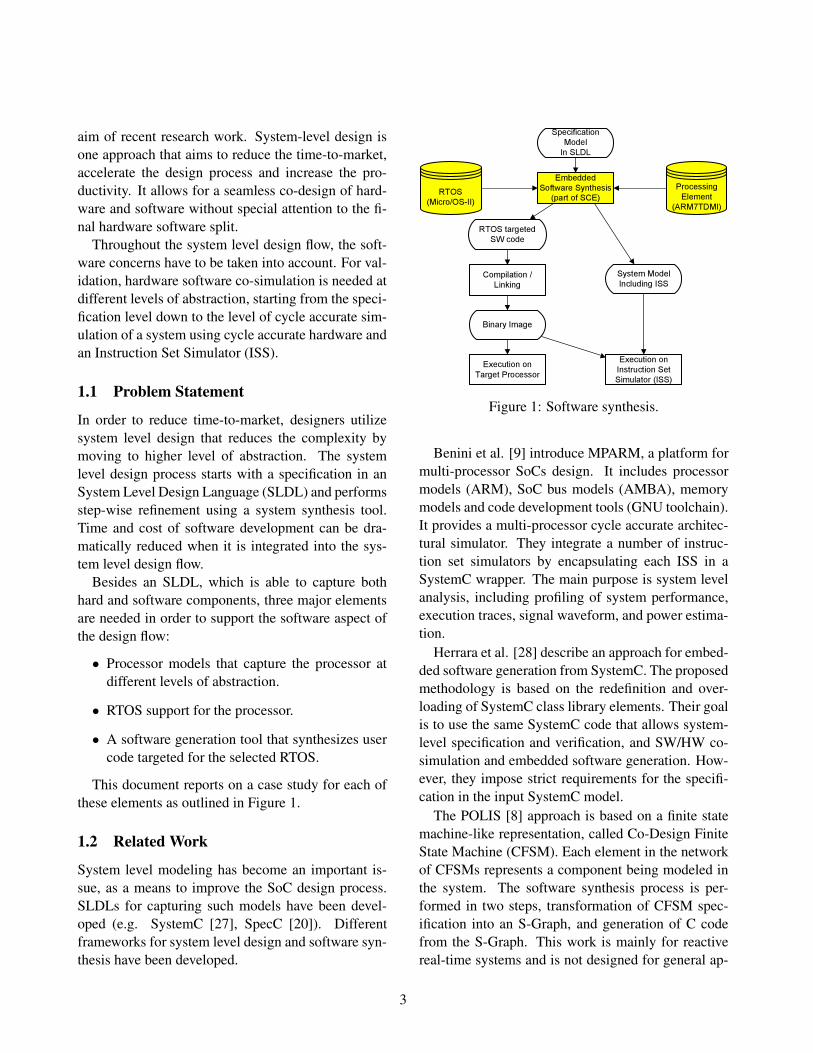
This document reports on a case study for each ofthese elements as outlined in Figure 1.
1.2 Related WorkSystem level modeling has become an important is-sue, as a means to improve the SoC design process.SLDLs for capturing such models have been devel-oped (e.g. SystemC [27], SpecC [20]). Differentframeworks for system level design and software syn-thesis have been developed.
Specification M od elI n SL D L
E m b ed d ed Softw ar e Sy nth es is(par t of SC E )
P r oces s ing E l em ent
(A R M 7T D M I )R T O S
(M icr o/O S-I I )
R T O S tar g eted SW cod e
C om pil ation / L ink ing
B inar y I m ag e
E x ecu tion on T ar g et P r oces s or
E x ecu tion on I ns tr u ction Set Sim u l ator (I SS)
Sy s tem M od el I ncl u d ing I SS
Figure 1: Software synthesis.
Benini et al. [9] introduce MPARM, a platform formulti-processor SoCs design. It includes processormodels (ARM), SoC bus models (AMBA), memorymodels and code development tools (GNU toolchain).It provides a multi-processor cycle accurate architec-tural simulator. They integrate a number of instruc-tion set simulators by encapsulating each ISS in aSystemC wrapper. The main purpose is system levelanalysis, including profiling of system performance,execution traces, signal waveform, and power estima-tion.
Herrara et al. [28] describe an approach for embed-ded software generation from SystemC. The proposedmethodology is based on the redefinition and over-loading of SystemC class library elements. Their goalis to use the same SystemC code that allows system-level specification and verification, and SW/HW co-simulation and embedded software generation. How-ever, they impose strict requirements for the specifi-cation in the input SystemC model.
The POLIS [8] approach is based on a finite statemachine-like representation, called Co-Design FiniteState Machine (CFSM). Each element in the networkof CFSMs represents a component being modeled inthe system. The software synthesis process is per-formed in two steps, transformation of CFSM spec-ification into an S-Graph, and generation of C codefrom the S-Graph. This work is mainly for reactivereal-time systems and is not designed for general ap-
3

plications.[11] presents a software refinement flow based on
the SystemC SLDL. It too makes use of integratingan instruction set simulator for hardware/software co-simulation.
SoC Designer with MaxSim Technology [6], is acommercial tool set for fast modeling, simulation anddebugging for complex System-on-Chips designs. Itprovides a graphical user interface for interactive sys-tem design, modeling and simulation. It providescycle-accurate and cycle-approximate models withsupport for SystemC. VaST Systems [36] offers a sim-ilar set of tools with a focus on embedded systems.Furthermore, CoWare [13] presents with the VirtualPlatform Designer an integrated solution for the cus-tom platform software design.
1.3 OutlineThis document is organized as follows, Section 2 de-scribes modeling of the processor (we selected theARM7TDMI [7]). This section will describe the ab-stract models, as well as the integration of a suitingISS (SWARM [14]). Second, Section 3 reports on theporting of an RTOS (µC/OS-II [29]) toward the se-lected processor core. Thirdly in Section 4, we willgive an overview how the generated SW code is tar-geted to the selected processor core.
Combining these three elements enables an integra-tion of the software development and simulation intothe system level design. The advantages of this in-tegration are shown with an example of car anti lockbreaks in Section 5.
2 ProcessorThe first key point for supporting a software develop-ment flow is to integrate a processor model into thesystem flow. By capturing the fundamental character-istics of the processor it makes the sytem design flowaware of a processor as a processing element, allowsto map software to it and to estimate the performance.Therefore we will first describe the selected proces-sor and its modeleding. We capture processor at twolevels of abstraction. First as an abstract behavioralmodel that yields early exploration results and second
as an integration of an Instruction Set Simulator (ISS)for a cycle accurate execution of the target binaries.
We chose an ARM core as a modeling example,since ARM is the industry leading provider of 32-bit embedded RISC microprocessor with almost 75%of the market [4]. In particular, we focused on theARM7TDMI.
2.1 ARM7TDMIAccording to [2] the ARM7TDMI core is at thepresent the industry’s most used 32-bit embeddedRISC microprocessor. We therefore selected this coreas a basis for the embedded software synthesis. Thecore provides high performance with very low powerconsumption. It is a RISC architecture, provideshigh instruction throughput and real-time interrupt re-sponse. The ARM7TDMI core is 100% binary com-patible with other ARM7 family cores and forward-compatible with the ARM9, ARM9E and ARM10Efamilies. The processor core is supported by a widerange of operating systems.
The ARM7TDMI has a Von Neumann architecture,with a single 32-bit data bus carrying both instruc-tions and data. Only load, store and swap instructionscan access data from memory and data can be 8-bit(bytes), 16-bit (halfwords) and 32-bit (words) [7].
2.1.1 Instruction Pipeline
As shown in Figure 2, the ARM7TDMI contains athree-stage pipeline.
Figure 2: ARM7TDMI Instruction Pipeline (Source[7]).
The three-stage pipeline allows concurrent opera-tion of the processing and memory system. While oneinstruction is executed, its successor is being decoded
4

at the same time and yet another instruction is beingfetched from the memory. The Program Counter (PC)refers to the instruction being fetched rather than theinstruction being executed. Therefore, the value ofthe PC is usually ahead by two address locations withrespect to the instruction in the execution stage.
2.1.2 Architecture
The ARM7TDMI [2], an implementation of theARMv4T architecture, is a 32-bit RISC processorwith a unified 32-bit data and address bus. Figure 3shows the architecture of the ARM7TDMI processorcore.
For increased memory efficiency, it supports boththe ARM and the Thumb instruction sets. While theARM instruction set is 32-bit wide and offers thefull instruction flexibility, the Thumb instruction setis limited to 16-bit. It only implements the mostfrequently used instructions, which according to [7]cover 65% of typical ARM code.
Each 16-bit Thumb instruction is internally trans-lated to the corresponding 32-bit counterpart. Thumbinstructions operate on the same register set, the same32-bit ALU and 32-bit memory address as the 32-bitARM instructions. With that, the Thumb instructionset allows for very compact code, while delivering atthe same time the performance of the 32-bit architec-ture.
The ARM7TDMI processor can be extended bycustom co-processors. Up to 16 co-processors canbe tightly coupled with the ARM7TDMI core for im-plementation of highly specialized additional instruc-tions. Detailed information about cycle counts andthe two instruction sets can be found in [2, 7].
To react to external events, the ARM7TDMI hastwo low active, level sensitive interrupts signals(nIRQ and nFIQ). nIRQ triggers the general purposeinterrupt and nFIQ the Fast Interrupt Request (FIQ)with a higher priority that the nIRQ. In addition to thehigher priority, the FIQ is optimized for faster execu-tion. It uses a reduced number of registers that areexclusively available during interrupt execution. Alower number of registers, minimizes the overhead ofcontext switching and reduces the interrupt overhead.
Figure 3: ARM7TDMI processor core (source [7]).
2.1.3 Bus Architecture
The ARM7 Thumb family processor cores are de-signed for use with AMBA on-chip bus architecture.ARM defined with the Advanced Microprocessor BusArchitecture (AMBA) [3] a widely used on-chip bussystem standard. It contains a group of busses, whichare used hierarchically as shown in Figure 4. The Ad-vanced High-performance Bus (AHB) is a system busdesigned for connecting high-speed components in-cluding ARM processors.
Although the initial ARM7TDMI design did notinclude a direct connection to the Advanced High-performance Bus (AHB), it can be connected througha wrapper, provided with the AMBA Design Kit [2],to the AMBA AHB.
The AHB is a multi-master bus that operates ona single clock edge. High performance is achieved
5

Figure 4: AMBA bus architecture (Source [3]).
by a pipelined operation that overlaps arbitration, ad-dress, and data phases, and by the usage of burst trans-fers. Split and retry transfers allow the slave to freethe bus if the requested data is temporary unavailable.The AHB also employs a multiplexed interconnectionscheme to avoid tri-state drivers.
2.2 Abstract Processor Modeling
In order to perform software synthesis in our designand refinement flow, based on the System-on-ChipEnvironment (SCE) [1], the target processor has tobe captured as a Processing Element (PE) [22]. A PEis a system component that processes data (performscomputation) by executing application specific algo-rithms. Examples for a PE are custom designed hard-ware or a programmable element (e.g. a processor).Each PE is captured at multiple levels of abstraction.Throughout the design process a model with an in-creasing amount of detail will be used.
A Behavioral Model of a PE is the most abstractmodel, which describes only the basic characteristics.It is used for the PE allocation and mapping of com-putation behaviors of the specification model duringarchitecture exploration.
Later in the design flow the OS Model is used asa template for inserting an RTOS model for abstractscheduling.
The Bus Functional Model is a pin-accurate model,that adds communication layers describing com-munication behavior of the component. For aprogrammable PE, a cycle-accurate Instruction SetModel is also used for clock cycle-accurate simula-tion of the PE.
Next sections describe in more detail each modelfor the selected processor, the ARM7TDMI.
2.2.1 Behavioral Model
A PE behavioral model is used for PE allocationduring architecture exploration and defines the basiccharacteristics of a PE. It enables the refinement flowto map user behaviors to it and to analyze the perfor-mance in various aspects.
The ARM7TDMI behavioral model contains threeaspects. It contains annotations for general databasemanagement, attributes and weight tables.
The annotations for the database management con-tain the basic information needed for managing thePE in the database. For example it includes a catego-rization of the ARM7TDMI PE as a general purposecore that is a 32-bit RISC. It also contains referencesto the more detailed models (OS Model, Bus Func-tional Model and Cycle Accurate Model). Further-more it contains the bus connectivity of the processorand its address range.
Figure 5 shows the behavioral model ofARM7TDMI. The ARM7TDMI is connectedthrough an AHB wrapper to the AMBA AHB. Forsimplicity however, we integrated this wrapper intoour ARM7TDMI model as if the processor had adirect interface to the AHB bus.
ARM7TDMIARM7TDMI
Behavioral Model
PortAAMBA AHB
master00x0FFFFFFF – 0xFFFFFFFF
AMBA AHBBUS
Figure 5: ARM7TDMI behavioral model.
Attribute annotations describe the basic character-istics of a PE. The attributes include, clock frequency,MIPS (million instructions per second), power con-sumption, instruction width, data width, data mem-ory and program memory. These attributes of theARM7TDMI have been defined according to the doc-umentation [7, 2, 4]. Some of the attributes are de-fined as ranges, to adapt the processor to the currentdesign needs. As one example, the clock frequencycan be set between 12.5 MHz and 75 MHz to meetthe application demands.
The main information of an PE behavioral model iscaptured in form of weight tables. The weight tablesare used for interpretation of the generic profiling re-
6
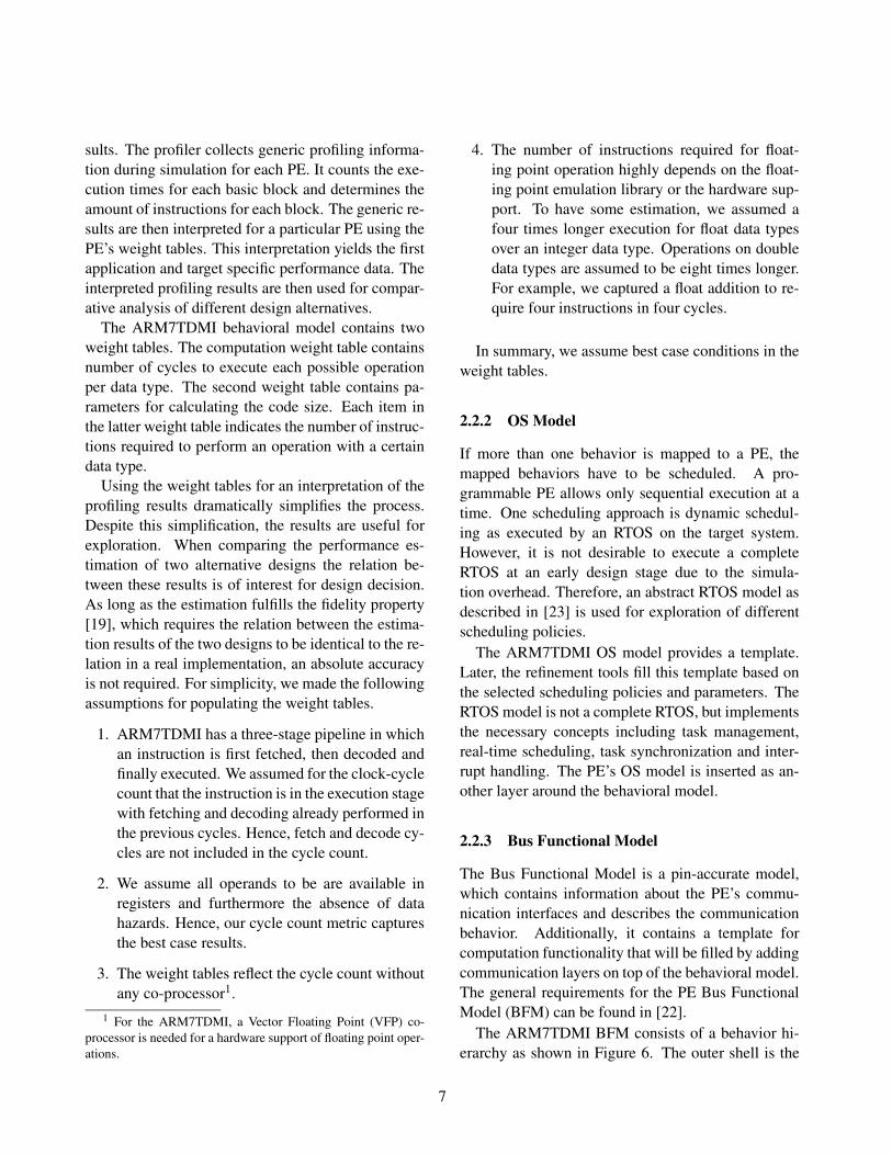
sults. The profiler collects generic profiling informa-tion during simulation for each PE. It counts the exe-cution times for each basic block and determines theamount of instructions for each block. The generic re-sults are then interpreted for a particular PE using thePE’s weight tables. This interpretation yields the firstapplication and target specific performance data. Theinterpreted profiling results are then used for compar-ative analysis of different design alternatives.
The ARM7TDMI behavioral model contains twoweight tables. The computation weight table containsnumber of cycles to execute each possible operationper data type. The second weight table contains pa-rameters for calculating the code size. Each item inthe latter weight table indicates the number of instruc-tions required to perform an operation with a certaindata type.
Using the weight tables for an interpretation of theprofiling results dramatically simplifies the process.Despite this simplification, the results are useful forexploration. When comparing the performance es-timation of two alternative designs the relation be-tween these results is of interest for design decision.As long as the estimation fulfills the fidelity property[19], which requires the relation between the estima-tion results of the two designs to be identical to the re-lation in a real implementation, an absolute accuracyis not required. For simplicity, we made the followingassumptions for populating the weight tables.
1. ARM7TDMI has a three-stage pipeline in whichan instruction is first fetched, then decoded andfinally executed. We assumed for the clock-cyclecount that the instruction is in the execution stagewith fetching and decoding already performed inthe previous cycles. Hence, fetch and decode cy-cles are not included in the cycle count.
2. We assume all operands to be are available inregisters and furthermore the absence of datahazards. Hence, our cycle count metric capturesthe best case results.
3. The weight tables reflect the cycle count withoutany co-processor1.
1 For the ARM7TDMI, a Vector Floating Point (VFP) co-processor is needed for a hardware support of floating point oper-ations.
4. The number of instructions required for float-ing point operation highly depends on the float-ing point emulation library or the hardware sup-port. To have some estimation, we assumed afour times longer execution for float data typesover an integer data type. Operations on doubledata types are assumed to be eight times longer.For example, we captured a float addition to re-quire four instructions in four cycles.
In summary, we assume best case conditions in theweight tables.
2.2.2 OS Model
If more than one behavior is mapped to a PE, themapped behaviors have to be scheduled. A pro-grammable PE allows only sequential execution at atime. One scheduling approach is dynamic schedul-ing as executed by an RTOS on the target system.However, it is not desirable to execute a completeRTOS at an early design stage due to the simula-tion overhead. Therefore, an abstract RTOS model asdescribed in [23] is used for exploration of differentscheduling policies.
The ARM7TDMI OS model provides a template.Later, the refinement tools fill this template based onthe selected scheduling policies and parameters. TheRTOS model is not a complete RTOS, but implementsthe necessary concepts including task management,real-time scheduling, task synchronization and inter-rupt handling. The PE’s OS model is inserted as an-other layer around the behavioral model.
2.2.3 Bus Functional Model
The Bus Functional Model is a pin-accurate model,which contains information about the PE’s commu-nication interfaces and describes the communicationbehavior. Additionally, it contains a template forcomputation functionality that will be filled by addingcommunication layers on top of the behavioral model.The general requirements for the PE Bus FunctionalModel (BFM) can be found in [22].
The ARM7TDMI BFM consists of a behavior hi-erarchy as shown in Figure 6. The outer shell is the
7

ARM7T D MI B u s F u n c t i o n a l Mo d e l
H a r d w a r e S h e l lC o r e
H AL
I RQ
AMBA AHB Ma s t e r P r o t o c o l
P r o t o c o l W r a p
MAC L i n kMAC L i n k
MAC L i n k
nIRQnF IQ
AMBA AHB
P I C
AMBA AHB S l a v e
P r o t o c o l
MAC L i n k
I n t e r r u p t D e t e c t
I n t e r r u p t C o n t r o l L o g i c
I n t r . S o u r c eI n t r . S t a t u sI n t r . Ma s k
T i m e r
AMBA AHB S l a v e
P r o t o c o l
MAC L i n k
I n t . G e n .
T i m e rC o n t r o l L o g i c
T MCT MVT ML
Figure 6: ARM7TDMI bus functional modeloverview.
bus functional shell that defines all pins of the pro-cessor. It contains three parallel executing behaviors:the processor core, a Programmable Interrupt Con-troller (PIC) and a timer. The processor core modelsthe bare core as described in the ARM documentation.The PIC is an interrupt controller that maps 32 exter-nal interrupts to the two core interrupt lines (nIRQ,nFIQ). The timer, disabled by default, can generateperiodic interrupts. The BFM communicates to theoutside via the AMBA AHB and interrupts can betriggered by one of the 32 external interrupt lines.
The bus implementation of the AMBA AHB itselfis taken from the bus database. The layer based im-plementation is realized in channels as described in[35]. Each layer is implemented in a separate chan-nel. In order to communicate, the according channelis instantiated inside the behavior.
The processor core contains two behaviors thatare executing in parallel. The Hardware AbstractionLayer (HAL) shell acts as a template. Throughout thesynthesis the template will be filled with the user com-putation behaviors. The Interrupt Request (IRQ) be-havior contains an interrupt handling logic that com-municates with the PIC and triggers execution of theinterrupt handlers.
Both behaviors the Hardware Abstraction Layer(HAL) and the IRQ communicate through the AHBmaster interface. The protocol layer interface iswrapped by the the protocol wrap channel before itconnects to the HAL shell. The wrapper disables
the interrupt handling while a bus transaction is inprogress. Doing so avoids preemption of a partiallyfinished transaction and is needed to maintain accu-rate protocol timing.
The IRQ behavior has two connections to the out-side, it terminates the nIRQ and nFIQ lines that sig-nal an interrupt from the PIC and a media access layerlink channel for the data connection to the PIC. Thisconnection is used for communicating with the PIC,in order to determine the actual source of an interruptand to clear the interrupt after handling it.
The PIC behavior is connected as a AHB slaveto the AHB bus, which is implemented through theAMBA AHB Slave Protocol channel. For a MediaAccess Control (MAC) layer access it uses the slaveversion of the link layer. Additionally a channel forthe interrupt detection is instantiated inside the PICthat performs the recognition of an interrupt from anexternal source. The Interrupt Control Logic behav-ior listens to the interrupt detection logic, sorts theincoming interrupts by priority and signals an aggre-gated interrupt to the core.
For the bus functional model, we captured a Pro-grammable Interrupt Controller (PIC) according toNEC’s System-on-Chip Lite+ definition in [25], witha few simplifications. The PIC provides 32 maskableinterrupts, with a 2-level programmable priority. It isbuild out of 4 basic blocks: low level interrupt de-tection modules, the interrupt control logic, registerbehaviors and the slave channels for the bus inter-face. The interrupt detect modules are responsible forrecognizing the interrupt condition on PE’s interruptlines and to change the interrupt status register (Intr.Status) according to the detected state.
The control logic behavior combines the interruptinformation of all detect modules, sorts them by pri-ority and signals the interrupt condition to the pro-cessor core through nIRQ and nFIQ if a non-maskedinterrupt is active. It then provides in Intr. Sourcethe highest priority active interrupt, which the proces-sor evaluates to select the interrupt service routine toexecute. The PIC also contains a mask behavior, sothat the core as the possibility to mask individual in-terrupts through the Intr. Mask register. For a cleanstartup, all interrupts are disabled by default.
Additionally, we modeled a programmable timer
8

unit also following NEC’s System-on-Chip Lite+ def-inition in [25]. The timer can be programmed to gen-erate periodic interrupts. It is used in the later de-scribed cycle accurate model for the actual RTOS tokeep track of time. The timer’s activity (reset, count-up, count-down) is controlled by the Timer ControlRegister (TMC) and the period through the TimerLoad Register (TML). These registers are availablevia the AHB interface. The timer is disabled by de-fault. It will be enabled by the RTOS running in thecycle accurate model as described in Section 3.2.4.
2.3 Cycle-Accurate Instruction Set Simula-tor
After the final stage of the embedded software syn-thesis the generated binaries have to be tested and thefinal system performance has to be evaluated. Forthat purpose an Instruction Set Simulator (ISS) is re-quired, that provides an accurate model of a processor(besides execution on the actual target processor) andaccepts the binary code of the target processor.
The embedded C code is generated in the softwaresynthesis as the final step of software refinement (seeSection 4). The C code is then compiled and linkedagainst all required libraries (e.g. RTOS library) toyield the final target binary. For the validation ofthe final target binary, co-simulation of hard and soft-ware can be used, which requires an ISS in the sys-tem level design flow. The ISS model, as part of thedatabase, then replaces parts of the bus functional pro-cessor model. A bus functional model of the targetdesign with an integrated ISS offers true hardware/-software co-simulation capabilities and yields cycleaccurate timing information for all aspects: softwareexecution, hardware execution2 and communication.
Next we will describe the selection of an ISS frommultiple candidates and cover its integration into thedatabase.
2.3.1 Selection of an ISS
An Instruction Set Simulator (ISS) is a simulationmodel that models the micro architecture of a proces-sor at the instruction set level. An ISS reproduces the
2 Assuming the custom hardware has been refined to RTL.
execution behavior of the actual processor by read-ing binary instructions, decoding and executing themwhile incrementally maintaining all relevant internalstate information of the processor. It emulates allcomponents accessible to the target assembly code,such as registers, program counter and processor sta-tus flags. Additionally, it can provide debug accessto internal state information of the processor that areusually hidden in a real hardware (e.g. detailed statusof the pipeline). Using an ISS eases software devel-opment and debugging by providing a deterministicexecution; especially useful for analyzing race condi-tions.
For integration into the system level design flow,we considered several instruction set simulators forthe ARM7 core:
1. SimpleScalar [10]
2. GDB ARMulator [15]
3. SWARM [14]
4. ARM ARMulator [5]
The selection process of the ISS was guided bythe requirements of the development and simulationenvironment. Especially the integration into the co-simulation environment poses some restrictions. Forexample, an ISS is typically implemented to run as astand alone process. However, for a co-simulation ithas to run within the context of the co-simulation en-gine. We have considered the following requirementsfor the ISS selection:
1. Cycle-accurate simulation of ARM7 micro-architecture.
2. Cycle callable interface (API) for cycle-by-cyclesimulation.
3. Access to the bus interface of the ISS.
4. Ability to handle interrupts and optionally toprovide an interrupt controller.
5. Availability of source code for the ISS.
6. Availability without license cost.
9
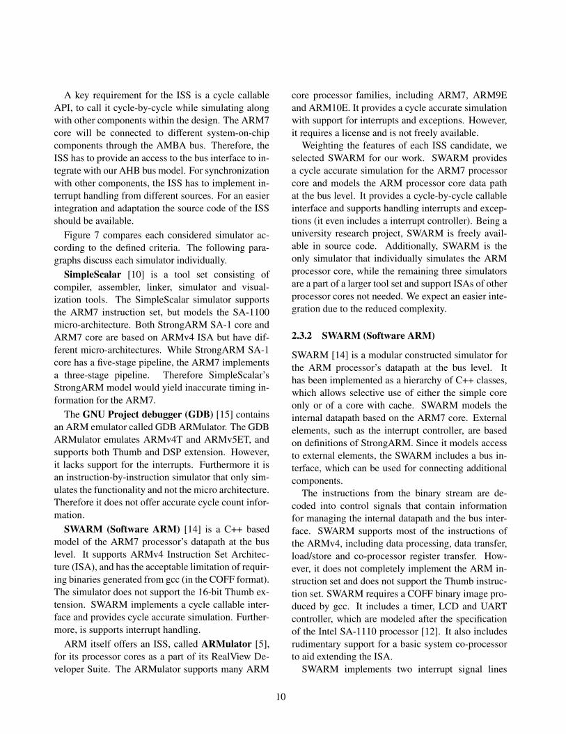
A key requirement for the ISS is a cycle callableAPI, to call it cycle-by-cycle while simulating alongwith other components within the design. The ARM7core will be connected to different system-on-chipcomponents through the AMBA bus. Therefore, theISS has to provide an access to the bus interface to in-tegrate with our AHB bus model. For synchronizationwith other components, the ISS has to implement in-terrupt handling from different sources. For an easierintegration and adaptation the source code of the ISSshould be available.
Figure 7 compares each considered simulator ac-cording to the defined criteria. The following para-graphs discuss each simulator individually.
SimpleScalar [10] is a tool set consisting ofcompiler, assembler, linker, simulator and visual-ization tools. The SimpleScalar simulator supportsthe ARM7 instruction set, but models the SA-1100micro-architecture. Both StrongARM SA-1 core andARM7 core are based on ARMv4 ISA but have dif-ferent micro-architectures. While StrongARM SA-1core has a five-stage pipeline, the ARM7 implementsa three-stage pipeline. Therefore SimpleScalar’sStrongARM model would yield inaccurate timing in-formation for the ARM7.
The GNU Project debugger (GDB) [15] containsan ARM emulator called GDB ARMulator. The GDBARMulator emulates ARMv4T and ARMv5ET, andsupports both Thumb and DSP extension. However,it lacks support for the interrupts. Furthermore it isan instruction-by-instruction simulator that only sim-ulates the functionality and not the micro architecture.Therefore it does not offer accurate cycle count infor-mation.
SWARM (Software ARM) [14] is a C++ basedmodel of the ARM7 processor’s datapath at the buslevel. It supports ARMv4 Instruction Set Architec-ture (ISA), and has the acceptable limitation of requir-ing binaries generated from gcc (in the COFF format).The simulator does not support the 16-bit Thumb ex-tension. SWARM implements a cycle callable inter-face and provides cycle accurate simulation. Further-more, is supports interrupt handling.
ARM itself offers an ISS, called ARMulator [5],for its processor cores as a part of its RealView De-veloper Suite. The ARMulator supports many ARM
core processor families, including ARM7, ARM9Eand ARM10E. It provides a cycle accurate simulationwith support for interrupts and exceptions. However,it requires a license and is not freely available.
Weighting the features of each ISS candidate, weselected SWARM for our work. SWARM providesa cycle accurate simulation for the ARM7 processorcore and models the ARM processor core data pathat the bus level. It provides a cycle-by-cycle callableinterface and supports handling interrupts and excep-tions (it even includes a interrupt controller). Being auniversity research project, SWARM is freely avail-able in source code. Additionally, SWARM is theonly simulator that individually simulates the ARMprocessor core, while the remaining three simulatorsare a part of a larger tool set and support ISAs of otherprocessor cores not needed. We expect an easier inte-gration due to the reduced complexity.
2.3.2 SWARM (Software ARM)
SWARM [14] is a modular constructed simulator forthe ARM processor’s datapath at the bus level. Ithas been implemented as a hierarchy of C++ classes,which allows selective use of either the simple coreonly or of a core with cache. SWARM models theinternal datapath based on the ARM7 core. Externalelements, such as the interrupt controller, are basedon definitions of StrongARM. Since it models accessto external elements, the SWARM includes a bus in-terface, which can be used for connecting additionalcomponents.
The instructions from the binary stream are de-coded into control signals that contain informationfor managing the internal datapath and the bus inter-face. SWARM supports most of the instructions ofthe ARMv4, including data processing, data transfer,load/store and co-processor register transfer. How-ever, it does not completely implement the ARM in-struction set and does not support the Thumb instruc-tion set. SWARM requires a COFF binary image pro-duced by gcc. It includes a timer, LCD and UARTcontroller, which are modeled after the specificationof the Intel SA-1110 processor [12]. It also includesrudimentary support for a basic system co-processorto aid extending the ISA.
SWARM implements two interrupt signal lines
10

ISSProcessor Core / Microarcitecture
supportedISA Modeled ISA complete
Thumb suppportCycle-by-
cycle Callable Interrupt Handling Cost License
SimpleScalar SA-1 core SA-11xx ARMv4T Yes
Thumb support Yes No but can be extended to include Free
SimpleScalar LLC license Acad. Non-comm. & comm. Academic.non-comm:free
GDB ARMulator ARM 6,7 ARMv4T,5TE Yes Thumb Support
No Instr-by-Instr
No/Yes Stops on interrupt Free GNU General Public License
SWARM ARM 6,7 ARMv4Binaries compiled with
gcc No Thumb Extension
Yes Yes Interrupt Controller Free GNU General Public License
ARM ARMulator ARM 7,9,9E,10E ARMv4T,5T,6 Yes Yes Yes "$" ARM Limited Academic License
Figure 7: Instruction-set simulators for ARM core.
(IRQ and FIQ) to interrupt the core and basic inter-rupt handling. It also includes an 32-bit interrupt con-troller based on the Intel SA-1110 [12] for synchro-nization with external peripheral devices.
SWARM attempts to realistically simulate thememory hierarchy for a ARM machine and even in-cludes a cache model. However, the external mem-ory bus interface is not complete. It provides an ab-stract untimed bus interface with 32-bit address anddata values. SWARM utilizes an internal memory of12 MB, starting at address zero, where the COFF bi-nary file is loaded into during initialization and wherethe execution starts from.
Figure 8 depicts the decisions during a write anda read memory access in SWARM. Accessing thememory is divided into three levels: the ARM coreinterface, the ARM processor interface that containscache, and the main memory. In case of a read cachemiss, the ARM processor halts the core, fetches thedata from the main memory into the cache and thenreleases the core. In case of a read cache hit, the datais available in the next cycle and the core execution isnot halted. Memory writes are implemented as writethrough that immediately appear in the external mem-ory.
SWARM has been implemented as a hierarchy ofC++ classes as outlined in the Figure 9. SWARM, be-ing a research project at the University of Glasgow,has not been completely implemented. However, thecurrent version is sufficient to execute binaries com-piled with gcc. Even so, the implementation containssome restrictions.
(a) Read (b) Write
Figure 8: SWARM memory accesses (Source [14]).
Core
Cache
Coprocessor
ARM7
LCD Ctrl.
UART Ctrl.
Timer InterruptCtrl.
SA-1110
IRQ
FIQ
IRQ
FIQ
MEMORY
SWARM
ADDR
DATA
0 31...... 0 31......
Figure 9: SWARM implementation (source [14]).
11

Our work includes some changes to SWARM in or-der better to match the real ARM core. We have per-formed three main alterations.
First, the interrupt lines nIRQ and nFIQ in theSWARM core have been incorrectly modeled as edgesensitive. Thus, an interrupt will not be detected if theinterrupt is disabled during the actual interrupt event.Even after enabling the interrupt, the according inter-rupt service routine is not executed. The ARM7TDMIcore, on the other hand, is level sensitive to the twointerrupt signal lines. Hence, enabling the interruptsafter the occurance of an interrupt, with the interruptline still being active, will trigger execution of the in-terrupt handler. We modified the SWARM core to im-plement level sensitive interrupts.
Second, we changed SWARM to avoid preemptionof an nIRQ interrupt. An interrupt triggered throughnFIQ has higher priority than an nIRQ triggered in-terrupt. Thus, an nFIQ interrupt can preempt an nIRQinterrupt. However, this preemption of an nIRQ inter-rupt is not handled correctly in SWARM, which losesthe order of execution. As a workaround we have dis-abled the nFIQ during execution of an nIRQ interrupt.Although this does not yield timing accurate results,it allows correct execution. As future work we plan toinvestigate fixing the FIQ interrupt handling.
Third, the interrupt controller included in SWARMis incomplete. For reasons of future optimization wehave decided not to use the included PIC, but modeleda PIC as a part of the bus functional model external toSWARM and disabled the SWARM internal PIC.
2.3.3 Cycle-Accurate PE Model
A cycle-accurate model of a programmable PE pro-vides cycle accurate simulation of the PE’s instruc-tion set and is called the instruction set model. Theinstruction set model replaces parts of the bus func-tional model. Therefore, the interface of the cycle-accurate model must exactly match the interface ofthe corresponding bus-functional model [22]. In otherwords, the cycle-accurate model is a SpecC behav-ior with identical external ports as the bus-functionalmodel, it adds a refined cycle-accurate timing.
In order to reach the cycle-accurate execution weintegrate the SWARM ISS into the database of ourrefinement flow. The refinement tool flow uses the
SLDL SpecC [20] for capturing the design and thedatabase elements. While SpecC is a superset of Clanguage, SWARM, on the other hand, is based onC++ classes. To integrate SWARM, we first created aC wrapper around the ISS (SWARM) that provides aC-level API, which can be called from SpecC behav-ior.
The SWARM with its C wrapper is embedded intoa SpecC behavior ARM7TDMI ISS. The wrapping be-havior ARM7TDMI ISS calls the ISS cycle by cycleand interfaces with the remaining design (e.g. exter-nal slaves on the same bus). It uses the C-API to trans-late between SWARM events and external events. Assuch it detects a SWARM bus access on the SWARMabstract bus interface and calls the channel of thebus functional model to execute the requested bustransfer. On the other hand it monitors the inter-rupt inputs and triggers an SWARM internal inter-rupt, should an interrupt occur. The wrapping behav-ior ARM7TDMI ISS advances the time in the SpecCsimulation according to the clock definition of the uti-lized ARM7 processor core.
Figure 10 shows the instruction set model of theARM7TDMI. It looks very similar to the bus func-tional model and reuses the same programmable in-terrupt controller. However, instead of the previouslyused core shell for abstract execution, it instantiateswrapping behavior ARM7TDMI ISS that contains theSWARM. The ARM7TDMI ISS connects to the AHBvia the AMBA AHB master protocol channel. Notethat due to the incomplete state of the SWARM in-ternal PIC and for future optimization, we do not usethe SWARM internal PIC. We neither use the LCD,UART controller or the internal timer.
As shown in Figure 10, the instruction setmodel has the identical pin level interface as theARM7TDMI bus functional model including wiresfor the AMBA AHB master and slave interface aswell as the interrupt wires. As in the BFM, the AHBwires are connected to the inlined master and slaveprotocol channels, which in turn are used by the me-dia access layer channels (AMBA Master MacLinkand AMBA Slave MacLink).
The two low active interrupt wires nIRQ and nFIQdirectly connect the PIC to the ARM7TDMI ISS. ThePIC signals a non-masked interrupt from any of the 32
12

ARM7T D MI B u s F u n c t i o n a l Mo d e lH a r d w a r e S h e l l
P I C
C o r e I S S AMB A AH B Ma s t e r P r o t o c o l
AMB A AH B S l a v e
P r o t o c o l
MAC L i n k
I n t e r r u p t D e t e c t
Interrupt C o ntro l L o g i c
Intr. S o urc eIntr. S ta tusIntr. M a s k
AMBA AHB
ARM7T D MI _I S S
nIRQnF IQ
S W ARM I S S
T i m e r
AMB A AH B S l a v e
P r o t o c o l
MAC L i n k
I n t . G e n .
T i m erC o ntro l L o g i c
T M CT M VT M L
Figure 10: SWARM instruction set model.
incoming interrupt wires to the ISS behavior throughthe either the nIRQ or the nFIQ line. The wrappingbehavior ARM7TDMI ISS checks both lines for eachcycle of the ISS. It forwards the interrupt signal tothe SWARM ISS by calling the C-level API for set-ting and clearing the IRQ/FIQ request. This triggersexecution of the interrupt service routine within theSWARM simulated code, which in turn then commu-nicates through the AMBA AHB with the PIC to de-termine the interrupt source.
Upon startup the wrapping behaviorARM7TDMI ISS initializes the SWARM, whichloads the binary file of the user program into theSWARM internal memory. Execution starts thenat address zero (SWARM internal memory). Thewrapper ARM7TDMI ISS calls the SWARM cycle-by-cycle in an endless loop. For each iteration, theARM7TDMI ISS behavior checks external interrupts,drives the ISS’s asynchronous inputs and drives theexternal bus interface if an according I/O instructionis executed within the SWARM ISS.
In a non-I/O processor cycle, the ARM7TDMI ISSadvances SpecC time for one processor clock periodand advances the ISS by a single cycle. In case ofexternal bus read or write, the ARM7TDMI ISS sim-ulates the bus by calling the bus protocol channelAMBA AHB Master Protocol imported from the busdatabase. Calling the protocol channel advances thesimulation time depending on the bus state and theselected slave, the ARM7TDMI ISS then advances the
ISS internal cycle count accordingly. It updates thePE ports for every external I/O operation according tothe processor state and bus state. The instruction setmodel is clock-cycle accurate and integrates with ex-ternal components in the design through the bus func-tional interface and interrupts.
3 Real-Time Operating SystemDuring the refinement process the designer may as-sign multiple behaviors to one software processingelement (CPU). Due to the inherent sequential ex-ecution nature of a processor, behaviors have to bescheduled either statically or dynamically. An RTOSis needed to run on the target processor for dynamicscheduling.
In the software synthesis stage, C code is generatedfrom the behaviors representing the software applica-tion running on the PE. The generated C code is crosscompiled to the target processor’s instruction set us-ing a cross compiler. The final executable is generatedby linking it against a customized RTOS. In the RTOStargeting stage, an actual RTOS is selected from thedatabase and is inserted in the code for providing nec-essary scheduling services.
In order to target an RTOS to a particular processor,the RTOS needs to be first adapted for the selectedtarget processor. This chapter starts with the selectionof an RTOS for the target ARM core. It then focuseson the integration of the selected RTOS.
3.1 RTOS SelectionAn RTOS is an operating system that has been de-signed for real time applications. The RTOS, throughits scheduling algorithms and deterministic nature,guarantees that the system deadlines can be met. Orto be more accurate, an RTOS provides services tim-ing deterministic so that it does not hinder the systemfrom meeting the deadlines. Deterministic executiontimes are a strict requirement, an additional goal is tominimum response time for interrupts. An RTOS pro-vides the system with the basic services of scheduling,multitasking and synchronization.
Many RTOSs are available, ranging from cost freeto commercial ones. Therefore, we describe first our
13

selection process. We have considered the followingRTOSs for our work:
1. RTEMS [30]
2. TinyOS [31]
3. eCos [16]
4. µC/OS-II [29]
Almost any RTOS can be adapted for targeting onthe ARM core. Therefore, based on the target proces-sor we have no strict requirement for the RTOS. How-ever, while considering the concurrency and map-ping performed in the refinement flow, there were fewrequirements that we considered while selecting theRTOS. The requirements that we took in to accountare listed below:
1. The RTOS should be able to support multitask-ing or concurrency.
2. It should have some mechanism for intertaskcommunication and synchronization.
3. Priority and first-come-first-serve scheduling hasto be supported.
4. The source code should be easy to adapt for anARM core.
5. The size for the RTOS should be small.
6. It should be freely available with detailed docu-mentation.
The first three requirements were the most impor-tant, although very basic, requirements for the RTOS.The remaining requirements were considered for aneasy adaptation to the ARM core.
Figure 11 shows a comparison of the four consid-ered RTOSs. It contains the information based on ourmetrics mentioned above.
Note that even though, µC/OS-II is no longer freelyavailable, we considered this RTOS in an older ver-sion available with source code in the book [29].
TinyOS [31], is an event-driven architecture andoffers only a limited concurrency. It supports onlya single process, therefore does not include process
management. Tasks are scheduled with a simple FIFOscheduler and cannot preempt other tasks. Only inter-rupts can preempt a task.
The three RTOSs - RTEMS, eCOS and µC/OS-IIare suitable for our work as they supported multitask-ing and have some mechanism for intertask communi-cation. Even though RTEMS offers more features ascompared to the other two, we selected µC/OS-II forour work due to the following reasons. The µC/OS-IIhas a very small footprint, yet at the same time it doesprovide all necessary features. Its source code is wellorganized, understandable and can be adapted easilyto the ARM core. In addition to that we had previousexperience with this RTOS.
3.2 MicroC/OS-IIµC/OS-II [29] is a multitasking real-time kernel thatprovides an execution environment for many tasks,where each task can utilize system resources. It pro-vides transfer of execution from one task to the other,so that resources can be used efficiently and timingdeadlines can be achieved. µC/OS-II provides low la-tencies for the kernel services. In order to achievetimeliness, priority scheduling is supported. Eachtask is assigned a priority and is scheduled accordingto it. Furthermore, preemption is supported, a higherpriority task may preempt execution of a lower prior-ity task in order to perform a time-critical function.
µC/OS-II is ROMable - it can execute as firmwarefrom the ROM of an embedded systems. It is portablesince it has been implemented mostly in ANSI C andcontains only a small amount of assembly code foradaptation to a particular processor core. In fact, it hasbeen ported to more than 40 different processor archi-tectures ranging from 8- to 64- bit microprocessors,microcontrollers and digital signal processors [29].
µC/OS-II provides a fully preemptive real-timekernel and priority scheduling that always executesthe highest priority ready task. It supports multitask-ing, where the application software can define up to56 tasks (8 tasks are reserved for µC/OS-II). Beinga real-time kernel, the execution time of most of theµC/OS-II functions and services is deterministic. Inother words, the time it takes to execute a function canbe estimated, which is necessary to make any real-time guarantees.
14

RTOS Cost Footprint Portable to ARM Scheduling Concurrency IPC Debug API
RTEMS Free 64K~128K Yes SCHED_RR, SCHED_FIFO pThreads
Semaphores, Mutexes, Condition-variable, Pqueues
GDB, DDD, Debug over- ethernet,
serial, BDM
RTEID/ORKID, uITRON , POSIX
TinyOS Free 400bytes Yes FIFO, Premptive
Limited - Two Threads of Execution: Tasks & Hardware event handler
Exclusive shared memory
TOSSIM (simulator + Debugger)
Custom
eCos Free 20K~200K Yes SCHED_RR, SCHED_FIFO Yes
Semaphores, Mutexes, Condition-
variableGDB uITRON,
POSIX
µC/OS-II $ 2K~20K Yes Fixed Priority, Preemptive Yes Semaphares,
Mutexes GDB POSIX
Figure 11: RTOS survey (source Jinhwan Lee).
µC/OS-II is a small real-time kernel with a memoryfootprint of about 20KB. It is a good candidate for ap-plication specific RTOS configuration, since it can bescaled down in footprint if the application does re-quire fewer features (down to 2K bytes of code spaceaccording to [29]).
3.2.1 MicroC/OS-II Structure
µC/OS-II is small with about 5,500 lines of code,mostly in ANSI C. The source code is well orga-nized. Figure 12 shows µC/OS-II the file structure andincludes the hardware/software architecture as well.The kernel code is organized into three segments:
Application Specific Code contains the user specificapplication software as well some code related tothe µC/OS-II. This includes initializing and start-ing the kernel as well as using the kernel specificAPI for task management, synchronization andcommunication.
Processor-Independent Code is the main code ofthe µC/OS-II kernel and is independent of theactual target processor. It provides the ker-nel services for task management, time manage-ment, semaphores, scheduling policy and mem-ory management.
Processor-Specific Code contains an adaptationlayer: the port to the selected target proces-sor, which varies with processors. This code
typically manipulates directly individual pro-cessor registers, for example in order to switchcontexts.
Figure 12: MicroC/OS-II hardware/software architec-ture (Source [29]).
15
3.2.2 Kernel and Kernel Services
The kernel, the heart of the operating system, pro-vides multitasking services so that the application canbe divided into smaller manageable tasks that sharethe same processor. Based on the scheduling policy,the kernel decides which task to run and switches be-tween tasks (context switch). It saves the context (i.e.the CPU registers) of the current task onto the it’sstack, loads the context of the new task and contin-ues executing the new task.
µC/OS-II kernel provides a number of system ser-vices, for a detailed description including their imple-mentation please refer to 12.
Task Management. µC/OS-II supports a multitask-ing environment with up to 56 application spe-cific tasks. In order to manage these tasks,µC/OS-II kernel provides services for creation,deletion, to change a task’s priority, to suspendand resume a task and to get more runtime infor-mation about a task.
Time Management. By use of a system timer inter-rupt, application specific between every 10ms to100ms, µC/OS-II keeps track of the real-time byincrementing a 32-bit tick counter. It allows theuser to set and query the time, as well as to sus-pend a task for a user specified time. InternallyµC/OS-II runs the scheduler for each timer tick.
Semaphore Management. µC/OS-II promotes intertask communication through shared data struc-tures. It simplifies the exchange of large amountsof data, but requires synchronization. Exclusiveaccess to the data is needed avoid corruption ofdata. µC/OS-II contains a semaphore implemen-tation and provides an API for the essential op-erations: creation, deletion, obtaining, queryingand returning of a semaphore.
Mutual Exclusion Semaphore Management. Inaddition to generic semaphores µC/OS-II pro-vides a specialized mutual exclusion semaphore(mutex). This is a binary semaphore that allowsto gain exclusive access to the resources andprovides additional features that reduce thepriority inversion problem.
Memory Management µC/OS-II provides supportfor dynamic memory allocation. It uses a fixedblock size allocation scheme to avoid fragmen-tation, as available memory is typically small inembedded applications. An application can allo-cate and deallocate these memory blocks.
The kernel also manages interrupts, it disables theinterrupts while entering the critical sections of thecode, e.g. the manipulation of kernel internal datastructures, and re-enables the interrupt when leavingthe critical section. This prevents that multiple tasksenter the critical section simultaneously and corruptdata. An interrupt can suspend or resume executionof a task. In case the resumed task is the highest pri-ority ready task, then it will execute as soon as theinterrupt handler has finished.
As mentioned for the Time Management services,µC/OS-II requires a periodic timer interrupt to keeptrack of time delays and timeouts. This periodic inter-rupt is referred to as the clock tick. It should be pro-vided with a frequency of 10 to 100 times a second.A higher frequency allows more fine grained timingdecisions, however it results in a higher overhead.
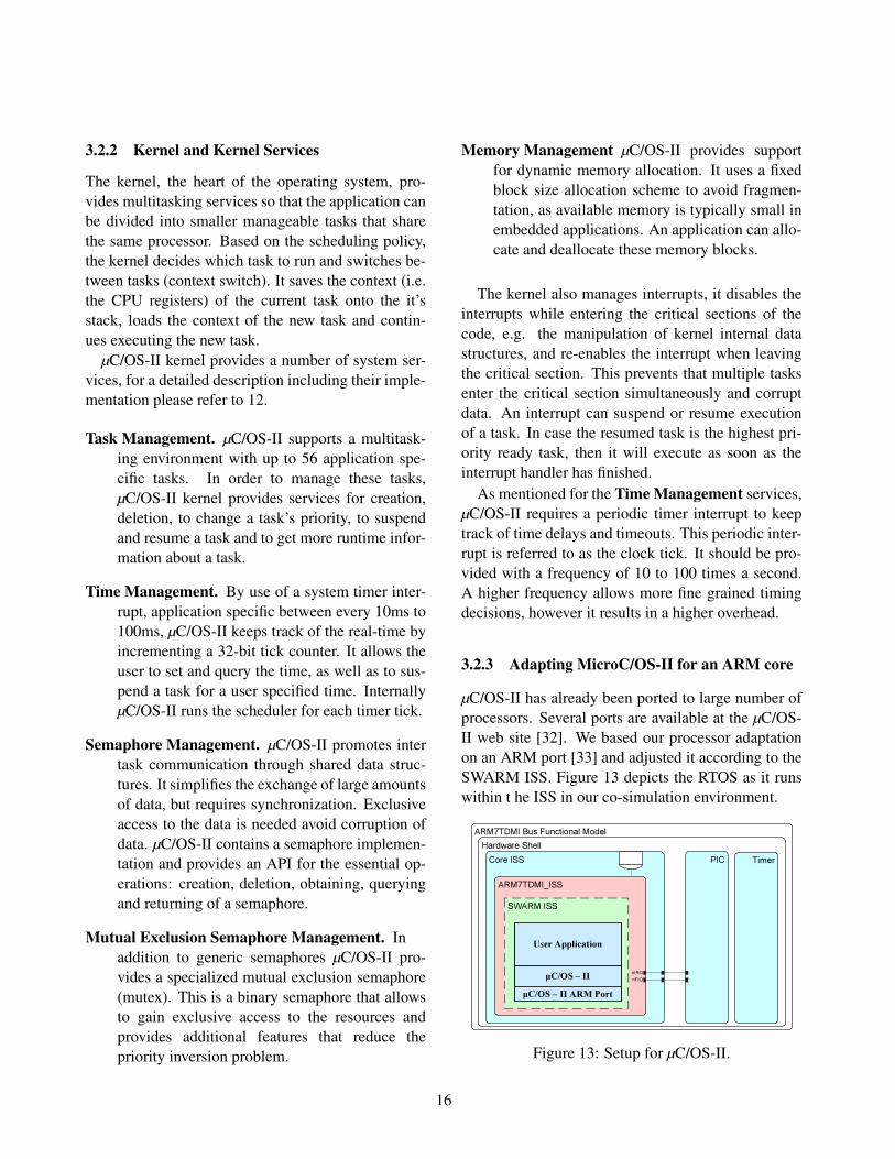
3.2.3 Adapting MicroC/OS-II for an ARM core
µC/OS-II has already been ported to large number ofprocessors. Several ports are available at the µC/OS-II web site [32]. We based our processor adaptationon an ARM port [33] and adjusted it according to theSWARM ISS. Figure 13 depicts the RTOS as it runswithin t he ISS in our co-simulation environment.
ARM7T D MI B u s F u n c t i o n a l Mo d e lH a r d w a r e S h e l l
P I CC o r e I S S
ARM7T D MI _I S S
nIRQnF IQ
S W ARM I S S
µC/O S – I I A R M P o r tµC/O S – I I
U s e r A p p l i c a t i o n
T i m e r
Figure 13: Setup for µC/OS-II.
16
The existing port for the ARM core mainly needsadjustments for the gcc cross compiler and the work-ing environment. As part of adaptation to the utilizedcompiler, we adjusted the sizes of the data types andthe resulting stack layout. The corrections for theworking environment include the address map, thecommunication with the PIC and the timer.
The µC/OS-II port contains the processor-specificcode of the operating system. The processor-independent code calls the specific code as C func-tions. The processor-specific code is implemented inC and/or in assembly code to perform register opera-tions.
This section discusses some key functions of theprocessor-specific code. A more detailed descriptioncan be found in the µC/OS-II book [29].
To protect the kernel internal data structures,µC/OS-II uses the concept of a critical section. Dur-ing execution of a critical section the interrupts haveto be disabled. This avoids preemption by an inter-rupt service routine, thus avoids unwanted schedul-ing events and makes execution of the critical sectionatomic. For this purpose, the port defines two func-tions that mark the start OS ENTER CRITICAL())and the end OS EXIT CRITICAL() of a critical sec-tion. These functions disable and re-enable theinterrupts respectively. They make use of twoassembly level functions OS CPU SR Save() andOS CPU SR Restore() that modify the CPSR regis-ter. OS CPU SR Save() disables all interrupts andreturns the list of the previously enabled interrupts.OS CPU SR Restore() restores the previous interruptstate by enabling all interrupts in the list.
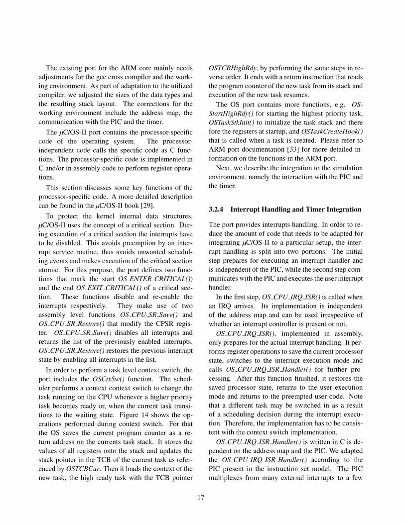
In order to perform a task level context switch, theport includes the OSCtxSw() function. The sched-uler performs a context context switch to change thetask running on the CPU whenever a higher prioritytask becomes ready or, when the current task transi-tions to the waiting state. Figure 14 shows the op-erations performed during context switch. For thatthe OS saves the current program counter as a re-turn address on the currents task stack. It stores thevalues of all registers onto the stack and updates thestack pointer in the TCB of the current task as refer-enced by OSTCBCur. Then it loads the context of thenew task, the high ready task with the TCB pointer
OSTCBHighRdy, by performing the same steps in re-verse order. It ends with a return instruction that readsthe program counter of the new task from its stack andexecution of the new task resumes.
The OS port contains more functions, e.g. OS-StartHighRdy() for starting the highest priority task,OSTaskStkInit() to initialize the task stack and therefore the registers at startup, and OSTaskCreateHook()that is called when a task is created. Please refer toARM port documentation [33] for more detailed in-formation on the functions in the ARM port.
Next, we describe the integration to the simulationenvironment, namely the interaction with the PIC andthe timer.
3.2.4 Interrupt Handling and Timer Integration
The port provides interrupts handling. In order to re-duce the amount of code that needs to be adapted forintegrating µC/OS-II to a particular setup, the inter-rupt handling is split into two portions. The initialstep prepares for executing an interrupt handler andis independent of the PIC, while the second step com-municates with the PIC and executes the user interrupthandler.
In the first step, OS CPU IRQ ISR() is called whenan IRQ arrives. Its implementation is independentof the address map and can be used irrespective ofwhether an interrupt controller is present or not.
OS CPU IRQ ISR(), implemented in assembly,only prepares for the actual interrupt handling. It per-forms register operations to save the current processorstate, switches to the interrupt execution mode andcalls OS CPU IRQ ISR Handler() for further pro-cessing. After this function finished, it restores thesaved processor state, returns to the user executionmode and returns to the preempted user code. Notethat a different task may be switched in as a resultof a scheduling decision during the interrupt execu-tion. Therefore, the implementation has to be consis-tent with the context switch implementation.
OS CPU IRQ ISR Handler() is written in C is de-pendent on the address map and the PIC. We adaptedthe OS CPU IRQ ISR Handler() according to thePIC present in the instruction set model. The PICmultiplexes from many external interrupts to a few
17

CPSRR0R1R2R3R4R5R6R7R8R9R10R11R12L RPC
R0R1R2R3R4R5R6R7R8R9R10R11R12SPL RPC
CPSRSPSR
CPSRR0R1R2R3R4R5R6R7R8R9R10R11R12L RPC
A f t e r
B e f o r e
B e f o r e
A f t e r
SPO S T CB
SPO S T CB
O ST CB Cu r O ST CB H i g h Rd y
SVCM o d e
Cu r r e n t t a s k s t a c k H i g h r e a d y t a s k s t a c kA RM Re g i s t e r s
Figure 14: Task level context switch (source [33]).
internal interrupts. In order to determine which ex-ternal interrupt has caused execution of the IRQ,OS CPU IRQ ISR Handler() reads the Interrupt Sta-tus register of the PIC and calls a the registered inter-rupt handler containing the actual user interrupt han-dler code. We defined and implemented a genericfunction UserIrqRegister() for registering a user func-tion as an interrupt handler for particular interrupt.
In order to keep track of time and for schedulingpurposes, µC/OS-II requires a periodic timer inter-rupt. This timer interrupt is generated by an exter-nal timer implemented in the bus functional model.The timer was implemented, like the PIC, accordingto NEC’s System-on-Chip Lite+ specification [25].
The registers of the timer are available via the AHBthrough an AHB slave interface. The timer inter-rupt is connected to an interrupt line of the PIC. Dur-ing the software startup, the function OSTimeTick isregistered as an interrupt handler associated with thetimer interrupt, the timer is enabled and programmedto generate a periodic interrupt every 10ms. There-
fore, the OS scheduling and time management func-tions are executed on a periodic basis.
4 Embedded Software Generation
Figure 15 shows an overview of the design flow. Thesystem level design process is composed of a grad-ual refinement, starting with the most abstract speci-fication model. Then the designer adds implementa-tion specific information and explores different alter-natives. With each refinement step more implemen-tation detail gets added to the system model. One re-finement step is the Architecture Refinement, whichintroduces processing elements and maps behaviorsto them. Another refinement step is the scheduling re-finement, which schedules execution on each process-ing element. The final refinement step, with respect tosoftware, is the the embedded software generation.
18

Architecture Model
Architecture R ef in em en t
S p ecif ica tion Model
S chedulin g R ef in em en t
S cheduled Model
C ModelE m b edded S of tw a re
C ros s C om p ila tion a n d L in k in g
T a rg et E x ecuta b le B in a ry
E m b edded S of tw a re S y n thes is
N etw ork R ef in em en t
N etw ork Model
T ra n s a ction L ev el ModelB us F un ction a l Model
E m b edded S of tw a re S y n thes is
Figure 15: System design flow [21].
4.1 Scheduling RefinementThe software synthesis is divided into two refinementsteps. The first step is the Scheduling Refinement.Here the designer specifies the scheduling parame-ters for processing elements to which multiple behav-iors have been mapped. Options are static and dy-namic scheduling. Within the dynamic scheduling ei-ther First Come First Serve (FCFS) or priority basedscheduling are selectable. In case of priority schedul-ing, the designer has to define the priority of eachtask.
As a result of the scheduling refinement, behaviorsare mapped to a processing element with a notion oftasks. For dynamic priority based scheduling a pri-ority is defined for each task. Tasks are scheduled
based on an abstract RTOS that is implemented asa separate channel instantiated in the processing ele-ment (see [24, 23]). The output model, the scheduledmodel, is still completely implemented in the SLDL.
4.2 Embedded Software Generation andRTOS Targeting
The second refinement step is the Embedded SoftwareSynthesis, which generates the target C code and per-forms the RTOS targeting. The software generationapproach is based on the work outlined in [38, 37].The software synthesis tool generates a set of softwaretasks from a partitioned design specification, the busfunctional model, captured in an SLDL, which in turnis the result of the scheduling refinement. The gener-ated software tasks implemented in target C code arethen scheduled by an real time kernel.
During the generation, the SLDL code of a behav-ior, which is mapped to a software task, is convertedto C code. All communication primitives are replacedwith plain C code as well. Task and synchronizationprimitives are replaced with calls to a generic RTOSwrapper, a thin RTOS abstraction layer. The C syn-thesis tool also generates interrupt handlers in caseinterrupts are used for synchronization with externalcomponents. It generates start-up code that registersthese interrupt handlers to the operating system.
The output of the embedded software generation istwofold. For one, the generated C code is reintegratedinto the input model (the bus functional model). Hereit replaces the original SLDL behaviors that have beenmapped to software tasks. It integrates into the re-maining system design with an abstract RTOS thathas been implemented on top of the SLDL [38]. TheC Model can be used for a fast validation of the gen-erated C code. It co-simulates with the remaining sys-tem design, usually containing custom hardware. Al-though the functional correctness can be validated, itdoes not yield accurate timing results.
Secondly, a flat C code, the Embedded Software,is generated for each programmable processing ele-ment. This code is designed for execution on the tar-get processor. The refinement step of Cross Compila-tion and Linking uses a target specific cross compilerto compile the generated C code and link it against
19

target and RTOS specific libraries. It produces a bi-nary for execution on the target processor.
We extended the refinement database to includesoftware components. For the integration of theARM7TDMI we populated the software databasewith the RTOS µC/OS-II, a µC/OS-II wrapper thatprovides RTOS abstraction API, the RTOS portingcode that contains the processor-specific code of theµC/OS-II, a software HAL that implements the MAClayer communication routines, which communicatewith the PIC and the timer. Additionally we includedan ISS specific libc that provides standard output rou-tines for debugging purposes.
We devised a generic file structure for the softwaredatabase to maximize reuse between SW components.As an example, we ensured that the communicationwith the PIC, implemented in C, is independent fromthe selected RTOS, the processor and the cross com-piler. Therefore, the same PIC communication codecan be used on all processors that are able to connectto the particular PIC, i.e. that can connect to the AHBin this case.
5 Experiments
In order to show the feasibility of the design flow, withrespect to the embedded software generation, we im-plemented a real life example and executed each stepof the refinement flow.
5.1 Example Application
Our example stems from the automotive industry. Weimplemented an anti lock break system as shown inFigure 16. It contains a single processor, an ARMv7,that runs the control application. The processor com-municates through an Advanced Microprocessor BusArchitecture (AMBA) AHB with a Controller AreaNetwork (CAN) controller. The CAN controller, atransducer, is accessible from the CPU through mem-ory mapped I/O. Five devices are connected on thesimulated CAN bus. One sensor that measures thebreak paddle position, a sensor for each wheel thatsenses the wheel’s rotation and a actuator for eachwheel that controls the asserted break pressure.
����������� ���
������� ����������� �"!����#�%$&�
����'(��)+* , - )�. . /+-021 � 1+343
5��%67���8�
9 - /4:4;�<�/+*2=�)4- > /�? ,4@BA2/4/�.C)2, :�, D )+*<�/+*2=�)4-
>�/�? ,2@EA /4/�.9 - /4:4;�FC:�. ��/
�D G+A�,2@(A2/4/�.C)2, :2, D )+*<�/+*2=�)4-
�D G+A�,4@(A2/4/+.9 - /2:+;�F�:�. ��/
HJI%K4L L M N O P Q N RTS
U�IK4V W Q X P O Q N RYSZ [ \
] \�^+H
_2X N ` a X W
Figure 16: Anti-lock break example architecture.
5.2 Refinement
We first captured the specification model of the ex-ample system. Then, we used the existing refinementflow to perform the refinement steps until the genera-tion of the bus functional model. Throughout the pro-cess, we used refinement decisions that match the de-sired target architecture (Figure 16).
The refinement tools use the database entries forthe ARM7TDMI processor for synthesizing the sys-tem models. The Architecture Model makes use ofthe abstract processor model (see Section 2.2.1). TheScheduling Refinement includes the OS model as de-scribed in Section 2.2.2. The bus functional commu-nication model contains the BFM of the ARM7TDMI(see Section 2.2.3) as well as the model of the bussystem AHB [35].
We then used the extended software synthesis toolsc2c (see Section 4) to generate the C code targetedtowards the RTOS. We cross compiled the generatedC code with a gcc cross compiler [26] that producesbinaries in the COFF format and linked against thenecessary database components (RTOS, RTOS wrap-per, RTOS port, HAL and libc). The result is a binaryin the COFF format that can be executed using theSWARM ISS.
We manually exchanged the bus functional modelof the ARM7TDMI in the systems BFM with the in-struction set model as described in Section 2.3.3. As aresult we achieved a bus-functional system model thatco-simulates hard and software and provides cycle ac-
20
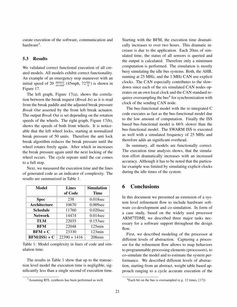
curate execution of the software, communication andhardware3.
5.3 Results
We validated correct functional execution of all cre-ated models. All models exhibit correct functionality.An example of an emergency stop maneuver with aninitial speed of 20 meters
second (45mph, 72 kmh ) is shown in
Figure 17.The left graph, Figure 17(a), shows the correla-
tion between the break request (Break In) as it is readfrom the break paddle and the adjusted break pressureBreak Out asserted by the front left break actuator.The output Break Out is set depending on the rotationspeeds of the wheels. The right graph, Figure 17(b),shows the speeds of both front wheels. It is notice-able that the left wheel locks, starting at normalizedbreak pressure of 50 units. Therefore the anti lockbreak algorithm reduces the break pressure until thewheel rotates freely again. After which in increasesthe break pressure again until the next locking of thewheel occurs. The cycle repeats until the car comesto a full stop.
Next, we measured the execution time and the linesof generated code as an indicator of complexity. Theresults are summarized in Table 1.
Model Lines Simulationof Code Time
Spec 238 0.018secArchitecture 10670 0.009sec
Schedule 11760 0.020secNetwork 14474 0.014sec
TLM 22035 0.153secBFM 22048 125min
BFM + C 23330 123minBFM(ISS) + C 22390 + 1416 208min
Table 1: Model complexity in lines of code and sim-ulation time.
The results in Table 1 show that up to the transac-tion level model the execution time is negligible, sig-nificantly less than a single second of execution time.
3Assuming RTL synthesis has been performed as well.
Starting with the BFM, the execution time dramati-cally increases to over two hours. This dramatic in-crease is due to the application. Each 20ms of sim-ulated time, the status of all sensors is queried andthe output is calculated. Therefore only a minimumcomputation is performed. The simulation is mostlybusy simulating the idle bus systems. Both, the AHB,running at 25 MHz, and the 1 MHz CAN use explicitclocks. The CAN especially contributes to the slow-down since each of the six simulated CAN nodes op-erates on an own local clock and the CAN standard re-quires oversampling the bus4 for synchronization withclock of the sending CAN node.
The bus-functional model with the re-integrated Ccode executes as fast as the bus-functional model dueto the low amount of computation. Finally the ISSbased bus-functional model is 66% slower than thebus-functional model. The SWARM ISS is executedas well with a simulated frequency of 25 MHz andtherefore adds an significant overhead.
In summary, all models are functionally correct.The execution time analysis shows, that the simula-tion effort dramatically increases with an increasedaccuracy. Although it has to be noted that the particu-lar example was limited by simulating explicit clocksduring the idle times of the system.
6 ConclusionsIn this document we presented an extension of a sys-tem level refinement flow to include hardware soft-ware co-development and co-simulation. In form ofa case study, based on the widely used processorARM7TDMI, we described three major tasks nec-essary for a software support throughout the designflow.
First, we described modeling of the processor atdifferent levels of abstraction. Capturing a proces-sor for the refinement flow allows to map behaviorsto programmable processing elements (processors), toco-simulate the model and to estimate the system per-formance. We described different levels of abstrac-tion, starting from an abstract, weight table based ap-proach ranging to a cycle accurate execution of the
4Each bit on the bus is oversampled (e.g. 12 times, [17])
21
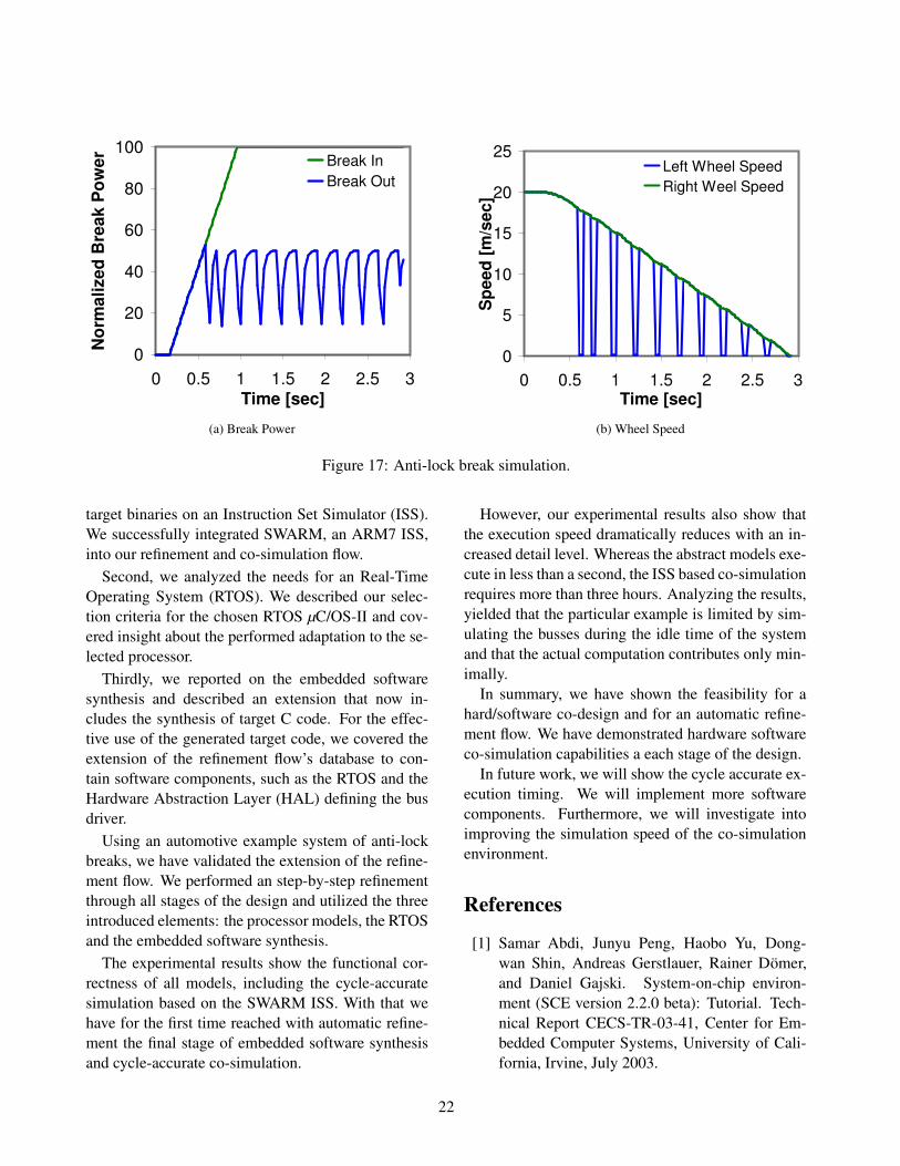
0
20
40
60
80
100
0 0.5 1 1.5 2 2.5 3Time [sec]
Norm
aliz
ed B
reak
Pow
er Break InBreak Out
(a) Break Power
0
5
10
15
20
25
0 0.5 1 1.5 2 2.5 3Time [sec]
Spee
d [m
/sec
]
Left Wheel Speed Right Weel Speed
(b) Wheel Speed
Figure 17: Anti-lock break simulation.
target binaries on an Instruction Set Simulator (ISS).We successfully integrated SWARM, an ARM7 ISS,into our refinement and co-simulation flow.
Second, we analyzed the needs for an Real-TimeOperating System (RTOS). We described our selec-tion criteria for the chosen RTOS µC/OS-II and cov-ered insight about the performed adaptation to the se-lected processor.
Thirdly, we reported on the embedded softwaresynthesis and described an extension that now in-cludes the synthesis of target C code. For the effec-tive use of the generated target code, we covered theextension of the refinement flow’s database to con-tain software components, such as the RTOS and theHardware Abstraction Layer (HAL) defining the busdriver.
Using an automotive example system of anti-lockbreaks, we have validated the extension of the refine-ment flow. We performed an step-by-step refinementthrough all stages of the design and utilized the threeintroduced elements: the processor models, the RTOSand the embedded software synthesis.
The experimental results show the functional cor-rectness of all models, including the cycle-accuratesimulation based on the SWARM ISS. With that wehave for the first time reached with automatic refine-ment the final stage of embedded software synthesisand cycle-accurate co-simulation.
However, our experimental results also show thatthe execution speed dramatically reduces with an in-creased detail level. Whereas the abstract models exe-cute in less than a second, the ISS based co-simulationrequires more than three hours. Analyzing the results,yielded that the particular example is limited by sim-ulating the busses during the idle time of the systemand that the actual computation contributes only min-imally.
In summary, we have shown the feasibility for ahard/software co-design and for an automatic refine-ment flow. We have demonstrated hardware softwareco-simulation capabilities a each stage of the design.
In future work, we will show the cycle accurate ex-ecution timing. We will implement more softwarecomponents. Furthermore, we will investigate intoimproving the simulation speed of the co-simulationenvironment.
References[1] Samar Abdi, Junyu Peng, Haobo Yu, Dong-
wan Shin, Andreas Gerstlauer, Rainer Domer,and Daniel Gajski. System-on-chip environ-ment (SCE version 2.2.0 beta): Tutorial. Tech-nical Report CECS-TR-03-41, Center for Em-bedded Computer Systems, University of Cali-fornia, Irvine, July 2003.
22

[2] Advanced RISC Machines Ltd. (ARM).ARM7TDMI (Rev 3) Product Overview. www.arm.com/pdfs/DVI0027B_7_R3.pdf.
[3] Advanced RISC Machines Ltd (ARM). AMBASpecification (Rev. 2.0), ARM IHI 0011A.www.arm.com/products/solutions/AMBA_Spec.html.
[4] Advanced RISC Machines Ltd. (ARM). PRO-CESSOR CORE OVERVIEW. www.arm.com/products/CPUs/index.html.
[5] Advanced RISC Machines Ltd. (ARM).RealView Developer Suite Instruction SetSimulator. www.arm.com/products/DevTools/RealViewISS.html.
[6] Advanced RISC Machines Ltd. (ARM).SoC Developer with MaxSim Technology.http://www.arm.com/products/DevTools/MaxSim.html.
[7] Advanced RISC Machines Ltd. (ARM).ARM7TDMI (Rev 4) Technical ReferenceManual, 2001. www.arm.com/pdfs/DDI0210B7TDMIR4.pdf.
[8] Felice Balarin, Massimiliano Chiodo, PaoloGiusto, Harry Hsieh, Attila Jurecska, Lu-ciano Lavagno, Claudio Passerone, AlbertoSangiovanni-Vincentelli, Ellen Sentovich, KeiSuzuki, and Bassam Tabbara. Hardware-Software Co-Design of Embedded Systems: ThePOLIS Approach. Kluwer Academic Publishers,1997.
[9] Luca Benini, Davide Bertozzi, AlessandroBogliolo, Francesco Menichelli, and MauroOlivier. ”mparm: Exploring the multi-processorsoc design space with systemc”. VLSI SignalProcessing, 41:169–182, 2005.
[10] Doug Burger and Todd M. Austin. The Sim-pleScalar Tool Set, Version 2.0. ComputerSciences Department, University of Wisconsin-Madison, June 1997.
[11] Jrome Chevalier, Maxime de Nanclas, Luc Fil-ion, Olivier Benny, Mathieu Rondonneau, Guy
Bois, and El Mostapha Aboulhamid. A Sys-temC Refinement Methodology for EmbeddedSoftware. IEEE Design and Test of Computers,99(99):148–158, 2006.
[12] Intel Corporation. Intel StrongARM SA-1110 Microporcessor Developer’s Manual.developer.intel.com/design/strong/manuals/278240.htm, October2001.
[13] CoWare. Virtual Platform Designer.www.coware.com.
[14] Michael Dales. SWARM 0.44 Documentation.Department of Computer Science, University ofGlasgow, November 2000. www.cl.cam.ac.uk/˜mwd24/phd/swarm.html.
[15] GDB Developers. GDB User Man-ual. www.gnu.org/software/gdb/documentation/.
[16] eCOS Community. eCOS home page.ecos.sourceware.org.
[17] Armin Bassemir Florian Hartwich. Theconfiguration of the can bit timing.www.can.bosch.com/, 1999.
[18] A. Gerstlauer; D. Shin; R. Doemer; D. Gajski.System-Level Communication Modeling forNetwork-on-Chip Synthesis. In Asia and SouthPacific Design Automation Conference, Shang-hai, China, January 2005.
[19] Daniel D. Gajski, Frank Vahid, Sanjiv Narayan,and Ji Gong. Specification and Design of Em-bedded Systems. Prentice Hall, 1994.
[20] Daniel D. Gajski, Jianwen Zhu, Rainer Domer,Andreas Gerstlauer, and Shuqing Zhao. SpecC:Specification Language and Design Methodol-ogy. Kluwer Academic Publishers, 2000.
[21] Andreas Gerstlauer, Rainer Domer, Junyu Peng,and Daniel D. Gajski. System Design: A Practi-cal Guide with SpecC. Kluwer Academic Pub-lishers, 2001.
23

[22] Andreas Gerstlauer, Gunar Schirner, DongwanShin, Junyu Peng, Rainer Domer, and Daniel D.Gajski. System-on-chip component models.Technical Report CECS-TR-06-10, Center forEmbedded Computer Systems, University ofCalifornia, Irvine, May 2006.
[23] Andreas Gerstlauer, Haobo Yu, and Daniel D.Gajski. RTOS modeling for system level de-sign. In Ahmed A. Jerraya, Sungjoo Yoo, Nor-bert Wehn, and Diedrik Verkest, editors, Embed-ded Software for SoC. Kluwer Academic Pub-lishers, 2003.
[24] Andreas Gerstlauer, Haobo Yu, and Daniel D.Gajski. RTOS Modeling for System Level De-sign. In Proceedings of the Design, Automationand Test in Europe (DATE) Conference, Mu-nich, Germany, March 2003.
[25] NEC Electronics (Europe) GmbH. System-on-Chip Lite +. User’s Manual. www.eu.necel.com/_pdf/A17158EE2V0UM00.PDF,April 2005.
[26] GNU. gcc (gcc-arm-coff version 2.95.3).ftp://ftp.gnu.org/gnu/gcc.
[27] Thorsten Grotker, Stan Liao, Grant Martin, andStuart Swan. System Design with SystemC.Kluwer Academic Publishers, 2002.
[28] F. Herrera, H. Posadas, P. Snchez, and E. Villar.Systematic Embedded Software Generationfrom SystemC. In Proceedings of the Design,Automation and Test in Europe (DATE) Con-ference, 2003. http://csdl.computer.org/comp/proceedings/date/2003/1870/01/18701% 0142abs.htm.
[29] Jean J. Labrosse. MicroC/OS-II: The Real-TimeKernel. CMP Books, 2002.
[30] RTEMS Steering Committee Members. Real-Time Operating System for Multiprocessor Sys-tems home page. www.rtems.com.
[31] TinyOS Committee Members. TinyOS homepage. www.tinyos.net.
[32] Micriµm. µC/OS-II Home Page.www.ucos-ii.com/arm/index.html#rtosports.
[33] Micriµm. µC/OS-II and The ARM Processor,Application Note, 2004.
[34] Gautam Sachdeva. Integration of an arm core ina system design flow. Master’s thesis, ElectricalEngineering and Computer Science, Universityof California, Irvine, March 2006.
[35] Gunar Schirner and Rainer Domer. Quantita-tive Analysis of Transaction Level Models forthe AMBA Bus. In Proceedings of the Design,Automation and Test in Europe (DATE) Confer-ence, Munich, Germany, March 2006.
[36] VaST Systems. VaST tools and mod-els for embedded system design.www.vastsystems.com.
[37] Haobo Yu. Software Synthesis for System-on-Chip. PhD thesis, Electrical Engineeringand Computer Science, University of California,Irvine, June 2005.
[38] Haobo Yu, Rainer Domer, and Daniel Gajski.Embedded software generation from systemlevel design languages. In Proceedings of theAsia and South Pacific Design Automation Con-ference (ASPDAC), Yokohama, Japan, January2004.
24