(modeling, simulation, and mitigation) - · pdf file(modeling, simulation, and mitigation)...
TRANSCRIPT

2/28/2015
1
“Wireless Channel Modeling”(Modeling, Simulation, and Mitigation)
Dr. Syed Junaid NawazAssistant Professor
Department of Electrical EngineeringCOMSATS Institute of Information Technology
Islamabad, Pakistan.
Courtesy of, Dr. Noor M. Khan (MA Jinnah University, Pakistan)Dr. M. N. Patwary(Staffordshire University, UK)Dr Muhammad Ali Imran (University of Surrey, UK)
Dr. Syed Junaid Nawaz
Current:
Assistant Professor: COMSATS Institute of IT, Islamabad.
Previous Institutes:
Research Fellow: Aristotle University of Thessaloniki, Greece,
Assistant Professor/HoD: Federal Urdu University AST, Islamabad
Research Fellow: Staffordshire University, UK
Research Fellow: Mohammad Ali Jinnah University, Islamabad.
Assistant Professor: Federal Urdu University of AST, Islamabad
Research Associate/ Lecturer: COMSATS Institute of IT, Abbottabad
Education:
Ph.D., Electronics Engineering, MA Jinnah University, Islamabad.
BS and MS, Computer Engineering, CIIT, Abbottabad.
2/30

2/28/2015
2
Dr. Syed Junaid Nawaz
Undergraduate Courses:
Analog Communications
Digital Communications
Digital Logic Design
Digital Systems
Computer Organization
Object Oriented Programming
Graduate Courses:
Advanced Topics in Wireless Communications
Adaptive Signal Processing
Wireless Channel Modeling
3/30
Dr. Syed Junaid NawazResearch Contributions in the area of Channel Moeling:
Syed Junaid Nawaz, B. H. Qureshi, N. M. Khan, “A Generalized 3-D Scattering Model for Macrocell Environment with Directional Antenna at BS,” IEEE Transactions on Veh. Technol. vol. 59, no. 7, pp. 3193-3204, May. 2010. [IF: 1.92].
Syed Junaid Nawaz, Noor M. Khan, Mohammad N. Patwary, and Mansour Moniri, “Effect of Directional Antenna on the Doppler Spectrum in 3-D Mobile Radio Propagation Environment," IEEE Transactions on Veh. Technol., vol. 60, no. 7, pp. 2895-2903, Jul. 2011. [Impact Factor: 1.92].
Syed Junaid Nawaz, M. Khawza, M.N. Patwary, and Noor M. Khan, “Superimposed Training Based Compressed Sensing of Sparse Multipath Channels”, IET Communications, Dec. 2012. [Impact Factor: 0.83].
M. Riaz, Syed Junaid Nawaz, and Noor M. Khan, “3D Ellipsoidal Model for Mobile-to-Mobile Radio Propagation Environments”, Wireless Personal Communication, Springer US, DOI: 10.1007/s11277-013-1158-0, Apr. 2013. [IF: 0.46]
Syed Junaid Nawaz, M. N. Patwary, Noor M. Khan, and Hongnian Yu, “3-D Gaussian Scatter Density Propagation Model Employing a Directional Antenna at BS,” in Proc. of IEEE, 5th Adv. Satellite Multimedia Systems Conf., vol. 1, Sep. 2010, pp. 395-400.
Syed Junaid Nawaz, Bilal H. Qureshi, Noor M. Khan, and M. Abdel-Maguid,” Effect of Directional Antenna on the Spatial Characteristics of 3-D Macrocell Environment”, in Proc. of IEEE, Int. Conf. on future comp. and commun., vol. 1, May 2010, pp. 552-556.
Syed Junaid Nawaz, Bilal H. Qureshi, and Noor M. Khan, ”Angle of Arrival Statistics for 3-D Macrocell Environment using Directional Antenna at BS”, in Proc. of IEEE, 13th Int. Multitopic Conf., vol. 1, Dec. 2009, pp. 1-5.
Syed Junaid Nawaz, S. Mohsin, and Ataul-aziz, ”Neural Network based MIMO-OFDM Channel equalizer using Comb-Type pilot arrangement”, in Proc. of IEEE, Int. Conf. on future comp. and comm., vol. 1, Apr. 2009, pp. 36 - 41.
Saif-Ur-Rehman, Syed Junaid Nawaz, M. N. Patwary, and M. Abdul Muguid, “Impact of Terrain Variance and Velocity on the Handover Performance of LTE Systems,” in Proc. of IEEE, Int. Conf. on Wireless Commun. and Signal Processing, vol. 1, Nov. 2010, pp.1-5.
4/30
2/28/2015
3
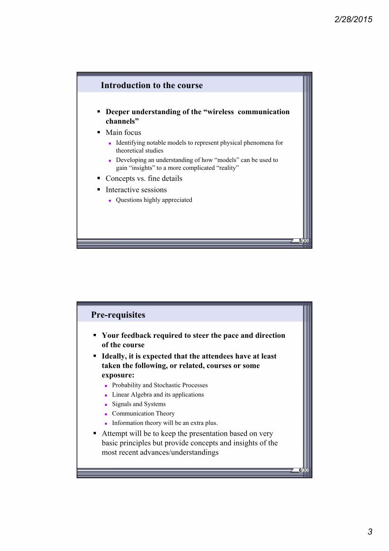
Introduction to the course
Deeper understanding of the “wireless communication channels”
Main focus Identifying notable models to represent physical phenomena for
theoretical studies
Developing an understanding of how “models” can be used to gain “insights” to a more complicated “reality”
Concepts vs. fine details
Interactive sessions Questions highly appreciated
5/30
Pre-requisites
Your feedback required to steer the pace and direction of the course
Ideally, it is expected that the attendees have at least taken the following, or related, courses or some exposure: Probability and Stochastic Processes
Linear Algebra and its applications
Signals and Systems
Communication Theory
Information theory will be an extra plus.
Attempt will be to keep the presentation based on very basic principles but provide concepts and insights of the most recent advances/understandings
6/30

2/28/2015
4
Grades Evaluation Policy
Assignments + Quizzes: 15 Marks
Research Project: 15 Marks
Mid –Term: 30 Marks
Final Exam: 40 Marks
Individual Research Project:
(Reproduction of the results presented in identified IEEE Transactions articles on wireless channel modeling)
7/30
Course Outline 1/4Communication Model
• Fundamentals of digital communication (through wired and wireless Channels)
Introduction to Wireless Propagation
• Wireless Propagation Basics
• Shadowing and multipath
Channel Modeling Parameters
• Multipath spread parameters Delay spread, angular spread and Doppler shift.
Coherence time, coherence bandwidth
Introduction to Multipath
• Direct Signal, Angle of Arrival, Time of Arrival, and Doppler Shift
• Direct and Reflected Signals
• Two scatterers and multiple scatterers model
• Link between moving terminals
• Path loss
• Large vs Small-Scale Fading
• Frequency flat vs frequency selective fading
• Slow vs fast fading
• Narrowband and wideband channels
8/30

2/28/2015
5
Course Outline 2/4Wireless Propagation Environments
• Cellular communications
• Street Canyon
• Vehicle to vehicle communications
• Underwater communications
• Aeronautical communications
• Satellite communications
Statistical, Empirical, Stochastic Geometry based Channel Models
• Path loss model
• Okumura Model
• Hatta Model
• The Clark Model
• Rayleigh distribution model
• Rician Distribution Model
• Land Mobile Satellite Channels
• Other notable models.
9/30
• Stochastic geometry based notable 2D and 3D models for angular, temporal, and Doppler spectrum characteristics of outdoor and indoor radio cellular propagation environments.
• Shape factors (angular spread, angular constriction, and direction of maximum fading)
• Second order statistics (level crossing rate, average fade duration, spatial correlation and coherence distance)
Course Outline 3/4
Directional Channels
• MIMO Channel modeling Statistical Modeling of the MIMO Channel
MIMO Channel Modeling Using the Multiple Point Scatterers
Generating Clustered Point-Scatterer Propagation Scenarios
• Massive MIMO channels
Mitigation Techniques
• Mitigation of Path loss and fading
• Diversity Techniques for Fading Multipath Channels
• Mitigation of ISI
• Estimation
• Equalization
• Mitigation of time variations
• Processing Techniques: LS, zero forcing, MMSE, and LMS
10/30

2/28/2015
6
Course Outline 4/4
Simulation Projects• Two-ray wall reflection model.
• Two-ray ground reflection model.
• Street Canyon Propagation
• Wideband Indoor Propagation
• Tapped Delay-Line Models – COST 207
• Rayleigh model.
• Rician model.
Recent research topics 5G Communications
Millimeter wave range.
Massive MIMO.
Small sized cells.
Measurement campaigns for F2M and M2M channels.
Aeronautical communication channels. 11/30
Introduction of Students
• Any student with non-engineering Background?
• Any students without qualifying Pre-requisites?
• Any Student with NO knowledge of wireless communications?
12/30

2/28/2015
7
Lecture 1
Introduction to the Course
Challenges of Wireless Communications
Brushing up the required tools Complex numbers – Not so complex
Phasors – A convenient notation
The scales of channel variation Large scale variations
Small scale variation
Understanding Small scale variations Multipath fading
13/30
Communication Problem
Message
Source
Channel
Destination
Channel
Source Destination
14/30

2/28/2015
8
Our first model
Message at the Source = x Channel
Multiplicative changes = h Additive changes = n
Message at the Destination = y
Channel
Source Destination
y=hx+n
15/30
Our first model
Channel
Source Destination
y=hx+n
• Wired Communication Channels• Dedicated• No Mobility
• Wireless Communication Channels• Fixed to Fixed (F2F)• Fixed to Mobile (F2M)• Mobile to Mobile (M2M)
16/30
2/28/2015
9
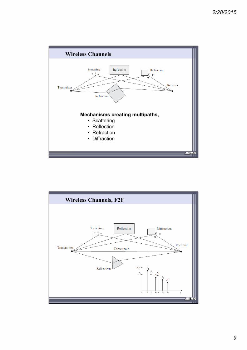
Wireless Channels
Mechanisms creating multipaths, • Scattering• Reflection• Refraction• Diffraction
17/30
Wireless Channels, F2F
18/30

2/28/2015
10
Wireless Channels, F2M
19/30
Wireless Channels, M2M
20/30

2/28/2015
11
Using Model to Gain Insights 1/4
y=hx+n
Assume x has two possible values (equal probability) 1
-1
Probability density function of x
Assume a nice channel with h=1 y=x+n To understand distribution of y, we need to model n
Probability that value is x
x1
1/2
-1
21/30
Using Model to Gain Insights 2/4
Additive noise is usually modelled as “Gaussian”
What does “Gaussian” imply?
Probability density function of n
-10 -5 0 5 100
0.2
0.4
0.6
0.8
1
values of n
pro
bai
lity
that
th
e va
lue
is n
var 2var 1var 0.5var 00
5.0
21
22/30

2/28/2015
12
Using Model to Gain Insights 3/4
Probability density function of y
Recall y=x+n for the nice channel and x is +1 or -1 with equal probability
-6 -4 -2 0 2 4 60
0.05
0.1
0.15
0.2
0.25
0.3
0.35
0.4
values of n
pro
bai
lity
that
th
e va
lue
is n
var 2var 1var 0.5
+1-1
5.0
21
23/30
Using Model to Gain Insights 4/4
We use a decision boundary to guess what was transmitted
-6 -4 -2 0 2 4 60
0.05
0.1
0.15
0.2
0.25
0.3
0.35
0.4
values of n
pro
bai
lity
that
th
e va
lue
is n
var 2var 1var 0.5
+1-1
If received y lies in this range, we assume x = +1 was transmitted
If received y lies in this range, we assume x = -1 was transmitted
5.0
21
Decision Boundary
24/30

2/28/2015
13
Using Model to Gain Insights 4/4
Errors in our “guess” may occur when noise pushes the input over the other side of the boundary
Cross-over probability is the probability of this error
-6 -4 -2 0 2 4 60
0.05
0.1
0.15
0.2
0.25
0.3
0.35
0.4
values of n
pro
bai
lity
that
th
e va
lue
is n
var 2var 1var 0.5
+1-1
>>
Cross-over Probability
5.0
21
25/30
Using Model to Gain Insights 4/4
We saw, larger variance implies higher probability of cross-over
To keep the cross-over probability low, larger variance of noise requires “larger input values” (e.g. +2,-2 or +3,-3)
-6 -4 -2 0 2 4 60
0.05
0.1
0.15
0.2
0.25
0.3
0.35
0.4
values of n
pro
bai
lity
that
th
e va
lue
is n
2 1 0.5
Equal Corss-over Probability
5.0
21
26/30

2/28/2015
14
Wireless Channel
Why wireless is different from wired link/network: No privacy – no dedicated “wire” channel
High interference due to the lack of privacy
Variations in the channel strength (why? will see shortly!)
Recall original model: y=hx+n
The variations in channel strength are modelled by h A multiplicative factor with the input, models the
attenuation/amplification caused by the channel
We have to revert to our original model:
y=hx+n
27/30
Variations in the channel strength
28/30

2/28/2015
15
Scales of variation
Increasing separation between the receiver and transmitter
An illustration from Goldsmith: Not realistic dataFast
Medium
Slow
29/30
Path Loss (very large scale)
Physical phenomena,
longer distance implies the radiation is spread over larger surface area
z
y
x
Source
Close
Far
Power attenuated proportional to inverse of a power of distance (2 in free space) => Power-Law Path Loss
30/30

2/28/2015
16
Shadowing (Large Scale)
Power attenuated due to absorption by several obstructions (just like light is obstructed by opaque objects, causing shadows)
Several independent random multiplicative factors: modelled by log-normal distribution – will see details later
1 Object
Source
3 Objects
2 Objects
31/30
Multipath Fading
Each wireless link is composed of several reflected paths and (optionally) the line-of-sight (specular) path
How does this change the channel strength?
32/41
2/28/2015
17
33
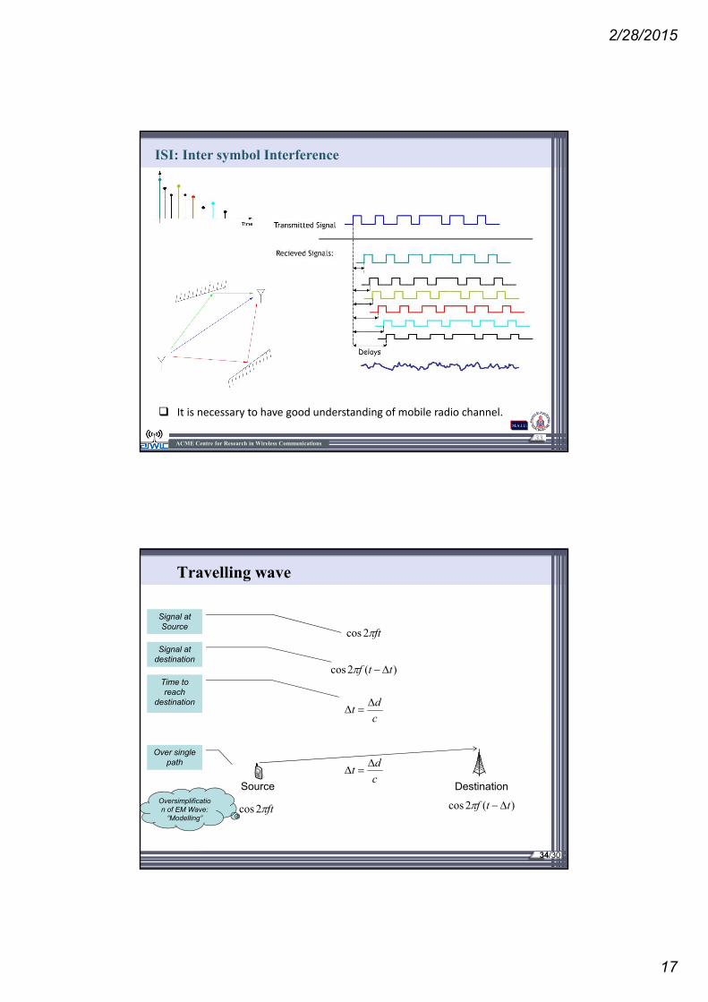
ISI: Inter symbol Interference
ACME Centre for Research in Wireless Communications
It is necessary to have good understanding of mobile radio channel.
Travelling wave
ft2cos
)(2cos ttf
c
dt
Source Destinationc
dt
ft2cos )(2cos ttf
Signal at Source
Signal at destination
Time to reach
destination
Over single path
Oversimplification of EM Wave:
“Modelling”
34/30

2/28/2015
18
Travelling wave over “Multipath”
c
dt 11
Source Destination
ft2cos )(2cos 1ttf
Path 1
Over multiple
path
Path 2
Path 3 c
dt 2
2
c
dt 3
3
12
3
)(2cos 2ttf )(2cos 3ttf
35/30
Phasors to visualize “Multipath”
How to visualize the sum of “shifted cosines”
)(2cos 1ttf )(2cos 2ttf )(2cos 3ttf
We need some “convenient” representation of cosines and its shifted versions
We will use the “complex numbers” and the “phasors” brief review follows!
36/30

2/28/2015
19
Complex numbers
A convenient representation of two dimensional space
One example is Cartesian plane
Another example is representation of a general sinusoid (any phase, any amplitude).
Since each general sinusoid can be expressed as sum of two components: One pure sine wave (zero phase delay) and another pure cosine wave (90 degree phase delay from pure sine).
If we use a vector (called phasor) to represent the “amplitude” and “phase delay angle” of a generalised sine wave, all general sinusoids span the two dimensional plane and we can
use complex numbers to express them as their components
37/30
Complex numbers
cos sinje j
arctan2 2cos sin
yj
j xZ x j y Z e Z j x y e
2 2Re ImZ Z Z
Imarctan
Re
ZZ
Z
Z x j y
22 2Z Z x j y x j y x y Z
Z x j y Rex Z Imy ZComplex No
Real
Imaginary
Magnitude
Euler’s formula
Convenient Notation
Conjugate
Thanks, Neikirk UT Austin
38/30

2/28/2015
20
Phasors to visualize “Multipath”
x, Re(Z)
y, Im(Z)
-1 1
1
-1
2-2
-2
2
0
If Z is a complex number: Z=x+j.y, It can be plotted on the complex plane
Z y=1
x=1
Z=1 +j.1
39/30
Phasors to visualize “Multipath”
• Any linear combination of cosine waves of the same period but different phase shifts is also a cosine wave with the same period, but (a third) different phase shift• Linear combination of a sine and cosine wave (which is just a sine wave with a phase shift of π/2)
• seen as “Euler’s formula” before• This is similar to the complex number notation and hence provides motivation to use complex plane to visualize the generalised cosines
a
bba
ba
arctancos
sincos
22
40/30

2/28/2015
21
Phasors to visualize “Multipath”
x, Re(Z)
y, Im(Z)
-1 1
1
-1
2-2
-2
2
0
Z y
x
•Each cosine with an arbitrary phase shift is a “phasor” (location vector of a complex number on the complex plane)
sinZy
cosZx
22 yxZ
x
yZ arctan
41/30
Travelling wave – moving source
Moving Source
Destinationc
dt
cos
2cos
ft
Z
tfft
ttfZ
),cos(
)22cos(
)(2cos
Recall
x, Re(Z)
y, Im(Z)
-1 1
1
-1
2-2
-2
2
0
Z
If the source moves, received cosine Z is a “randomly”
rotating phasor and rotates at a rate at which the received
phase changes
42/30

2/28/2015
22
Constructive-Destructive multipath sum
Each path changes independently over time: three random vectors sum up at the destination
Source Destination
12
3
x, Re(Z)
y, Im(Z)
-1 1
1
-1
2-2
-2
2
0Zr
x, Re(Z)
y, Im(Z)
-1 1
1
-1
2-2
-2
2
0
Zr
43/30
Thank You
Questions and Discussions
44/30