modeling of fluid flow inside ump's francis turbine
TRANSCRIPT
MODELING OF FLUID FLOW INSIDE UMP’S FRANCIS TURBINE USING
COMPUTATIONAL FLUID DYNAMICS (CFD)
MUHAMMAD NUR IZNEI BIN HASHIM
Thesis submitted in fulfilment of the requirements
for the award of the degree of
Bachelor of Mechanical Engineering
Faculty of Mechanical Engineering
UNIVERSITY MALAYSIA PAHANG
NOVEMBER 2009
SUPERVISOR’S DECLARATIO�
I hereby declare that I have checked this project and in my opinion, this project
is adequate in terms of scope and quality for the award of the degree of Bachelor
of Mechanical Engineering.
Signature
Name of Supervisor : DEVARAJAN A/L RAMASAMY
Position : LECTURER
Date : 23 NOVEMBER 2009
iii
STUDE�T’S DECLARATIO�
I hereby declare that the work in this project is my own except for quotations
and summaries which have been duly acknowledged. The project has not been
accepted for any degree and is not concurrently submitted for award of other
degree.
Signature
Name : MUHAMMAD NUR IZNEI BIN HASHIM
ID Number : MA06017
Date : 26 NOVEMBER 2009

iv
ACK�OWLEDGEME�TS
In the name of Allah, the Most Benevolent and the most Merciful. Every sincere
appreciation and gratitude is only to God. Only by His Kindness and Guidance that this
thesis is finally completed .I am grateful and would like to express my sincere gratitude
to my supervisor Mr. Devarajan a/l Ramasamy for his ideas, invaluable guidance,
continuous encouragement and constant support in making this research possible. He
has always impressed me with his outstanding professional conduct, his strong
conviction for science, and his belief that a degree program is only a start of a life-long
learning experience. I appreciate his consistent support from the first day I applied to
graduate program to these concluding moments. I also sincerely thanks for the time
spent proof reading and correcting my many mistakes. My sincere thanks go to all my
friends and collages who helped me in many ways and made my stay at UMP pleasant
and unforgettable. I acknowledge my sincere indebtedness and gratitude to my parents
for their love, dream and sacrifice throughout my life. I cannot find the appropriate
words that could properly describe my appreciation for their devotion, support and faith
in my ability to attain my goals. I would like to acknowledge their comments and
suggestions, which was crucial for the successful completion of this study.
v
ABSTRACT
This project describes and explains the fluid flow conditions and parameters
within a Francis Turbine with regards to each part of the turbine in contact with the
working fluid and all working parts of the turbine. The process of obtaining the fluid
flow condition and characteristic within the turbine is done by Computational Fluid
Dynamics (CFD) simulation. Before CFD simulation is done, a model of the Francis
needs to be selected as there are wide ranges of model ranging from conventional usage
to demonstration purposes. Considering the availability of the turbine and data, UMP’s
Gunt Hamburg Demonstration Francis Turbine HM150.20 was selected. The project
was then continued by referring to this model. The project was divided into 3 main parts
that is experiment on the actual Francis Turbine in order to get real data which will then
be used to validate the simulation data by the mean of comparing efficiency curve. The
next part is Computer Aided Design (CAD) modeling based on the Gunt Hamburg
Demonstration Francis Turbine HM150.20 dimensions and specifications obtained from
the manufacturer and measurement on the actual turbine. The CAD modeling was done
with consideration to the working parts of the turbine and external parts which are not
bounded by the fluid flow region are placed with equivalent readout such as torque
which is measured directly at the runner. The third part of the project would be the
simulation by using CFD code. During this part, the constructed CAD model is
subjected to boundary and flow conditions obtained from experiment and run to obtain
the required data. After simulation is done by CFD code, the data obtained is validated
by comparing the efficiency curve to verify that the simulation result is correct and
fulfill the condition needed for analysis. The significance of the project is that it
provides comprehensive and complete flow condition within UMP’s Gunt Hamburg
Demonstration Francis Turbine HM150.20 which can be used for further studies on the
fluid flow inside the turbine and efficiency improvement for the turbine.
vi
ABSTRAK
Projek ini menceritakan dan menerangkan keadaan pergerakan dan parameter
bendalir di dalam “Francis Turbine” dengan perihal bahagian-bahagian yang berada
dalam lingkungan bendalir dan bahagian operasi “Turbine” tersebut. Proses
mendapatkan pergerakan bendalir dan karakteristik dilakukan melalui Pengiraan
Bendalir Dinamik (CFD). Sebelum CFD dilakukan, model “Francis Turbine” harus
dipilih terlebih dahulu kerana terdapat seleksi “Francis Turbine” yang besar dari jenis
conventional ke jenis demonstrasi. Berdasarkan seleksi data dan “Francis Turbine” yang
sedia ada, Gunt Hamburg Demonstration Francis Turbine HM150.20 UMP dipilih.
Projek ini terbahagi kepada 3 bahagian iaitu experimentasi ke atas “Francis Turbine”
bagi mendapatkan data yang akan digunakan bagi mengesahkan data yang bakal
diperolehi dari simulasi. Kemudian process memodel “Francis Turbine” melalui Rekaan
Bantuan-Komputer (CAD) berdasarkan spesifikasi yang diperoleh dari pengeluar dan
ukuran yang diperolehi dari “Turbine” tersebut. Ketiga ialah proses simulasi melalui
kod CFD. Ketika bahagian ini, model CAD yang dibina disimulasi dengan keadaan
sempadan dan pergerakan bendalir yang diperoleh dari eksperimen untuk mendapatkan
data yang deiperlukan. Selepas simulasi dilakukan oleh kod CFD, data melaui proses
pengesahan melalui perbandingan bentuk lengkung keberkesanan simulasi dan
eksperimen bagi memastikan ianya betul dan memenuhi keadaan diperlukan untuk
analysis pergerakan bendalir. Signifikasi projek ini ialah ia membekalkan keadaan
pergerakan bendalir yang komprehensif dan lengkap didalam Gunt Hamburg
Demonstration Francis Turbine HM150.20 UMP yang boleh digunakan untuk kajian
akan datang mengenai pergerakan bendalir di dalam “Turbine” disamping
penambahbaikkan keberkesanan “Turbine” tersebut.
vii
TABLE OF CO�TE�T
Page
STATEME�T OF AWARD i
SUPERVISOR’S DECLARATIO� ii
STUDE�T’S DECLARATIO� iii
ACK�OWLEDGEME�TS iv
ABSTRACT v
ABSTRAK vi
TABLE OF CO�TE�TS vii
LIST OF TABLES x
LIST OF FIGURES xi
LIST OF ABBREVIATIO�S xiii
CHAPTER 1 I�TRODUCTIO�
1.1 Introduction 1
1.2 Project Objective 2
1.3 Project Scope 2
1.4 Project Background 3
1.5 Problem Statement 3
1.6 Problem Solving 4
CHAPTER 2 LITERATURE REVIEW
2.1 Introduction 6
2.2 Turbine 6
2.3 Francis turbine 7
2.4 Reaction Turbine 8
2.5 Cavitations 8
2.6 Efficiency 10
2.7 Runner 11
2.8 Guiding vanes 12
viii
2.9 Computer-Aided Design 13
2.10 Computational Fluid Dynamics 14
2.11 Velocity Profile 17
CHAPTER 3 METHODOLOGY
3.1 Introduction 18
3.2 Flow Chart 18
3.2.1 Flow chart of the study for PSM 1 18
3.2.2 Flow chart of the study for PSM 2 19
3.3 Model Selection 21
3.4 Experimental Setup 21
3.4.1 Experimentation 22
3.4.1.1 Pre-experiment Procedure 22
3.4.1.2 Experiment Procedure 24
3.5 Computer-Aided Design (CAD) Modeling 28
3.5.1 Pre-modeling Process 29
3.5.2 Modeling Process 29
3.6 Computational Fluid Dynamics (CFD) 29
CHAPTER 4 RESULT A�D DISCUSSIO�
4.1 Introduction 32
4.2 Experiment Result 32
4.3 Simulation Result 35
4.3.1 Numerical Results 35
4.3.2 Graphical Results 39
4.3.2.1 Pressure 40
4.3.2.1.1 Pressure Flow Trajectories inside Fluid 40
4.3.2.1.2 Pressure Contour on the Internal Surfaces
of the Francis Turbine
41
4.3.2.1.3 Pressure Contour Cut Plot inside Fluid
Flow Region
42
ix
4.3.2.2 Velocity 43
4.3.2.2.1 Velocity Flow Trajectories inside Fluid
4.3.2.2.2 Velocity Contour on Turbine Internal
Surfaces
44
4.3.2.2.3 Velocity Contour Cut Plot inside Fluid
Flow Region
45
4.3.2.3 Density 46
4.3.2.3.1 Density flow Trajectories inside fluid 46
4.3.2.3.2 Density Contour on Turbine Internal
Surfaces
46
4.4 Validation 47
4.5 Discussion 48
CHAPTER 5 CO�CLUSIO� A�D RECOMME�DATIO�
5.1 Introduction 52
5.2 Conclusion 52
5.3 Recommendations 53
REFERE�CES 54
APPE�DIXES 56
x
LIST OF TABLES
Table �o. Page
3.1 Project definition for the simulation 33
4.1 Flow data obtained from experiment 36
4.2 Flow data obtained from COSMOS simulation for speed range 0-
1000rpm
38
4.3 Flow data obtained from COSMOS simulation for speed range 0 -
1700rpm
41

xi
LIST OF FIGURES
Figure �o. Page
2.1 A basic electric generating turbine 6
2.2 A large scale conventional Francis Turbine found in dams 7
2.3 Example of cavitations in Francis Turbine 9
2.4 CAD model of the Gunt Hamburg Francis turbine runner 11
2.5 CAD model of the Gunt Hamburg Francis turbine guiding vanes and
its position on the Francis Turbine
12
2.6 Velocity profile diagram for internal flow for laminar and Turbulent
Flow Velocity Profiles
18
3.1 Flow chart of the study for PSM 1 19
3.2 Flow chart of the study for PSM 2 20
3.3 (a) Gunt Hamburg HM 150.20 drawing 21
(b) Gunt Hamburg HM 150.20 actual image 21
3.4 Runner and guiding vanes position with arrow representing
flow direction
23
3.5 Drawing of the pressure gauge and pipe joint which joint
the pump work bench to the Francis Turbine
23
3.6 Drawing of the braking belts that are attached to the force 24
3.7 Drawing of the vane angle indicator on the Francis Turbine 25
3.8 Drawing of the pulley with tachometer readout point 25
3.9 Drawing of force readout on the force gauge 26
3.10 Drawing of the pressure gauge with relative to Francis
Turbine position
27
3.11 Assembled view of the CAD model 28
3.12 Exploded view of the Francis Turbine 28
4.1 Efficiency versus speed graph for experiment data 34
4.2 Efficiency versus speed graph for simulation data for
0-1000rpm range
37
4.3 Efficiency versus speed graph for simulation data for
0-1700rpm range
39
4.4 Pressure flow inside the fluid in Francis Turbine 40
xii
4.5 Pressure contour on the internal surfaces of the Francis Turbine 41
4.6 Pressure contour cut plot in the fluid flow region 42
4.7 Pressure flow inside the fluid in Francis Turbine 43
4.8 Velocity contour on the internal surfaces of the Francis Turbine 44
4.9 Velocity contour cut plot in the fluid flow region 45
4.10 Density flow inside the fluid in Francis Turbine 46
4.11 Density contour on the internal surfaces of the Francis Turbine 46
4.12 Efficiency versus speed graph for experiment and simulation data 47
4.13 Foreign build-up on turbine face 48
4.14 Dent and scratches on guiding vanes 49
4.15 Guiding vanes disorientations 49
xiii
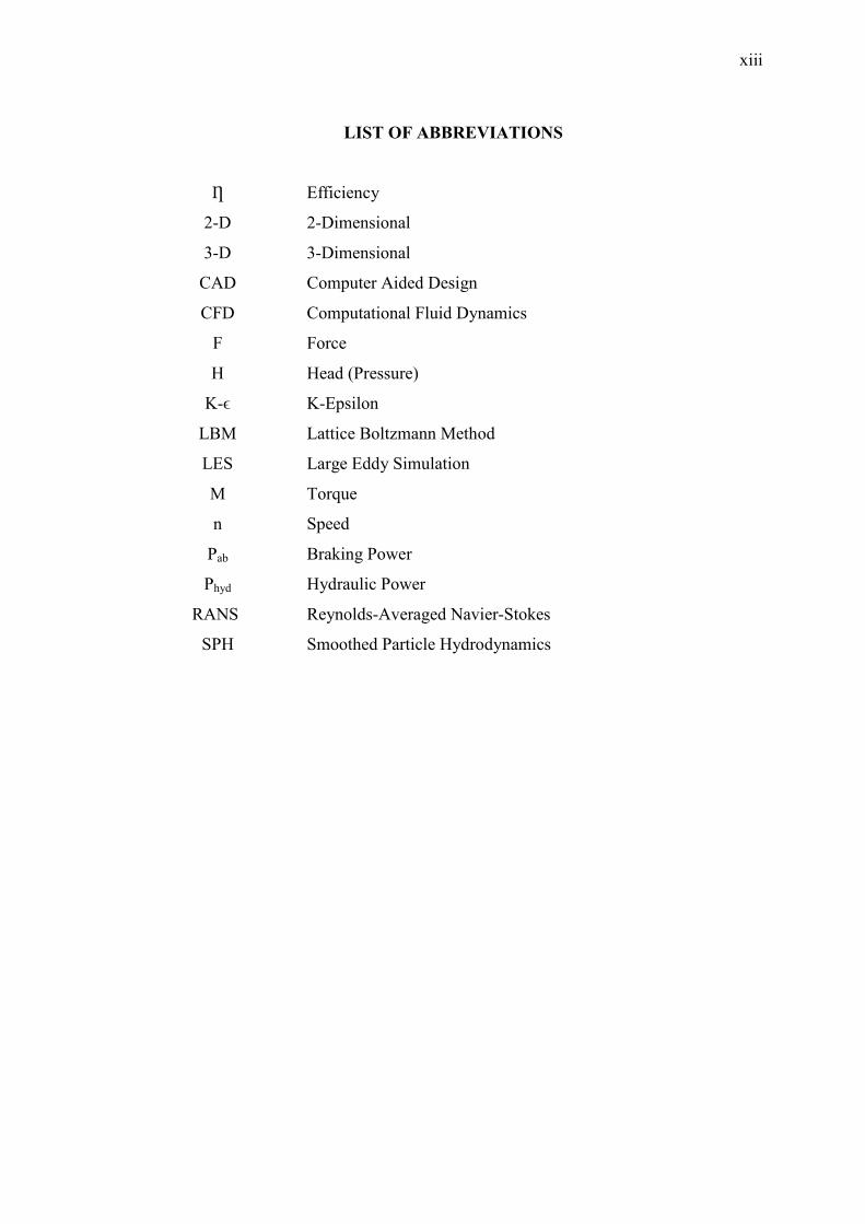
LIST OF ABBREVIATIO�S
Ƞ Efficiency
2-D 2-Dimensional
3-D 3-Dimensional
CAD Computer Aided Design
CFD Computational Fluid Dynamics
F Force
H Head (Pressure)
K-ϵ K-Epsilon
LBM Lattice Boltzmann Method
LES Large Eddy Simulation
M Torque
n Speed
Pab Braking Power
Phyd Hydraulic Power
RANS Reynolds-Averaged Navier-Stokes
SPH Smoothed Particle Hydrodynamics

1
CHAPTER 1
I�TRODUCTIO�
1.1 I�TRODUCTIO�
Francis turbine is a type of hydropower reaction turbine that contains a runner
that has water passages through it formed by curved vanes or blades. The runner blades,
typically 6 to 19 in number, cannot be adjusted. As the water passes through the runner
and over the curved surfaces, it causes rotation of the runner. The rotational motion is
transmitted by a shaft to a generator. It is an inward flow reaction turbine that combines
radial and axial flow concepts where both concepts are flow are integrated into the
turbine in order to make the water flow within the generator to be able to generate
highly efficient rotation and energy transfer to the shaft and runners.
Francis Turbine is a hydropower reaction turbine that was discovered and
invented by James Bicheno Francis in the year 1848. James Bicheno Francis was a
British-American Engineer; he was born in Southleigh, Oxfordshire in England and
immigrated to the United States at age 18. In 1834 he got a job at the Locks and Canal
Company of Lowell, Massachusetts and became Chief Engineer in 1837 where he there
remained at the company for his entire career.
It was in the years 1848 where he made his greatest achievement and
contribution to the scientific society where he designed and created Francis Turbine
which was a great improvement of the earlier turbines created by Jean-Victor Poncelet,
Benoît Fourneyron, and Uriah Atherton Boyden to create a turbine with 90% efficiency
which was far greater than what had been achieved by the earlier generation turbines.

2
He applied scientific principles and testing methods to produce the most
efficient turbine design ever. More importantly, his mathematical and graphical
calculation methods improved the state of the art of turbine design and engineering. His
analytical methods allowed confident design of high efficiency turbines to exactly
match a site's flow conditions. The Francis Turbine was considered to be a more
efficient successor to the Boyden turbine. His analysis was proven as he opt to use
skewed blade which is able to harvest energy from flowing water both radial and axial
flow.
1.2 PROJECT OBJECTIVE
There are several objectives that are needed to be completed by the end of this
project which are:
1. To create a complete, accurate and working 3D model of UMP’s Francis
Turbine in CAD.
2. To subject the constructed 3D model of UMP’s Francis Turbine to boundary and
initial condition such as the working environment of a Francis Turbine so that
the fluid flow can be analyzed by a CFD code.
3. To study the flow characteristic of a Francis Turbine by means of analyzing the
simulation result and interpreting them into their respective characteristic.
1.3 PROJECT SCOPE
This project concentrates it study on the flow analysis within the turbines runner
under similar operating conditions of the actual turbine. Graphical and numerical
simulation is done to determine and display the velocity profile and pressure
distribution within the turbine runner and use the information to improve the efficiency
of the turbine. The scopes of study are as follows:
1. CAD solid modeling (SOLIDWORK)
2. CFD analysis (COSMOS)
3. Turbine parameter modification.
4. Turbine efficiency improvement.
5. Validation study of efficiency and flow characteristic.

3
1.4 PROJECT BACKGROU�D
The purpose of this project is to identify the pressure and velocity profile
distribution within the runner of a Francis Turbine. From this project, we can observe
and determine the pattern of velocity profile and pressure distribution by using CFD
simulation program after the 3D modeling of the Francis Turbine is made.
Before the simulation is started, we need to determine the values of the Francis
Turbine’s working condition such as its pressure, mass flow rate etc. It is based on these
reference values that we apply the values to the CAD model. Besides, our simulation is
based on the design of the Francis Turbine. After finish the simulation, we need to
devise a method to increase the performance and efficiency of the turbine.
Basically, the project revolves around the idea of investigating the effect and
distribution of velocity profile and pressure within a turbine and based on the result
obtained from the simulation to improve the turbine’s efficiency.
1.5 PROBLEM STATEME�T
In turbines, one of the most important characteristic or properties of hydro
powered turbines is the overall efficiency of the turbine which can be translated as how
much of the original power of the flowing water is successfully converted or translated
into electrical energy in case of damps. Turbines development have been mainly been
focused on a creating a well rounded turbine with high efficiency value. However the
actual efficiency and performance of this turbine may vary according to ambient
conditions and working environment. It’s based on this assumption that we are to
analyze UMP’s Francis Turbine to determine its rated efficiency.
The variation in the calculated efficiency compared to the theoretical efficiency
of Francis Turbine occur caused by several factors which is different from the ideal
condition of the turbine. Since turbines constructed by the supplier are practically
identical, the factors that affect this efficiency difference surely must lay within the
turbine’s configuration e.g. the guiding vanes angle etc. Next is the existence of
4
cavitations which reduces the turbine’s overall efficiency and at the same time breaks or
creates and propagates cracks at the runner’s blade thus rendering the turbine defective.
When cavitations occur, the blades on the runner gather bubbles and pop. The
pop of the bubbles break and indent the runner and guiding vanes that help the water or
fluid move from the middle of the runner to the leading edge of the runner. The sound
of cavitations is like pumping gravel through the volute or case. If the pump is
experiencing cavitations, the ball valve is slowly turned clockwise to reduce input flow
rate on the discharge side of the pump on a centrifugal pump and the gravel noise will
reduce as a sign that the cavitations has been reduced. Cavitations will destroy the
runner very fast by imploding bubbles on the runner and guiding vanes until the pump
will not run anymore.
1.6 PROBLEM SOLVI�G
To study the flow characteristic of a Francis Turbine, several methods could be
used. The easiest would be the path chosen in the project that is to attempt to model the
fluid flow inside the turbine itself by mean of CAD modeling and CFD simulation. The
method is the easiest and most effective since the variables and condition can be change
at ease and the result from the modeling will be presented in both numerical and
graphical method.
Several ways can be done to improve of optimize the efficiency of UMP’s
Francis Turbine; the simple method is to adjust the guiding vanes, so that the angle of
entrance is changed and the cavitations is reduced or eliminated from the flow. The
more complex method is modifying the turbines geometry and physical properties such
as surface roughness, internal diameter, runner diameter etc. However trial and error
method for each solution can be wasteful especially if done manually that is through
fabrication process. So the best option for analysis is via simulation process which is
more effective at testing and less costly. Simulation process which is proposed consist
of the first part is the actual model simulation and based on the obtained results, certain
parameters will be adjusted for optimum and maximum efficiency of the turbine.
5
CHAPTER 2
LITERATURE REVIEW
2.1 I�TRODUCTIO�
The purpose of this chapter is to provide a review of the past research related to
the current research done which is turbine, Francis Turbine, reaction turbine,
cavitations, efficiency, hydro powered turbine, runner, guiding vanes, CAD, CFD, and
velocity profile.
2.2 TURBI�E
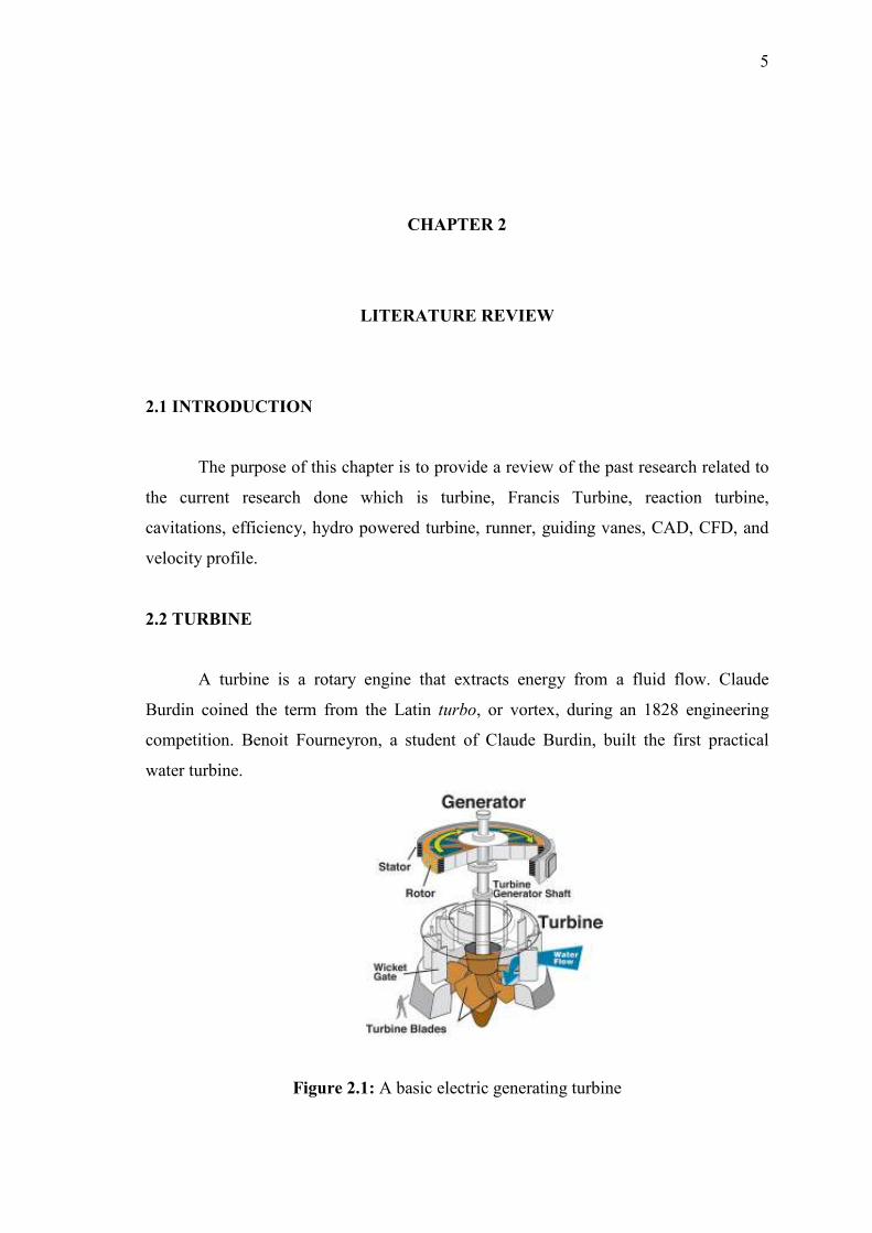
A turbine is a rotary engine that extracts energy from a fluid flow. Claude
Burdin coined the term from the Latin turbo, or vortex, during an 1828 engineering
competition. Benoit Fourneyron, a student of Claude Burdin, built the first practical
water turbine.
Figure 2.1: A basic electric generating turbine
6
The simplest turbines have one moving part, a rotor assembly, which is a shaft
with blades attached. Moving fluid acts on the blades, or the blades react to the flow, so
that they rotate and impart energy to the rotor. Early turbine examples are windmills and
water wheels. Gas, steam, and water turbines usually have a casing around the blades
that contains and controls the working fluid
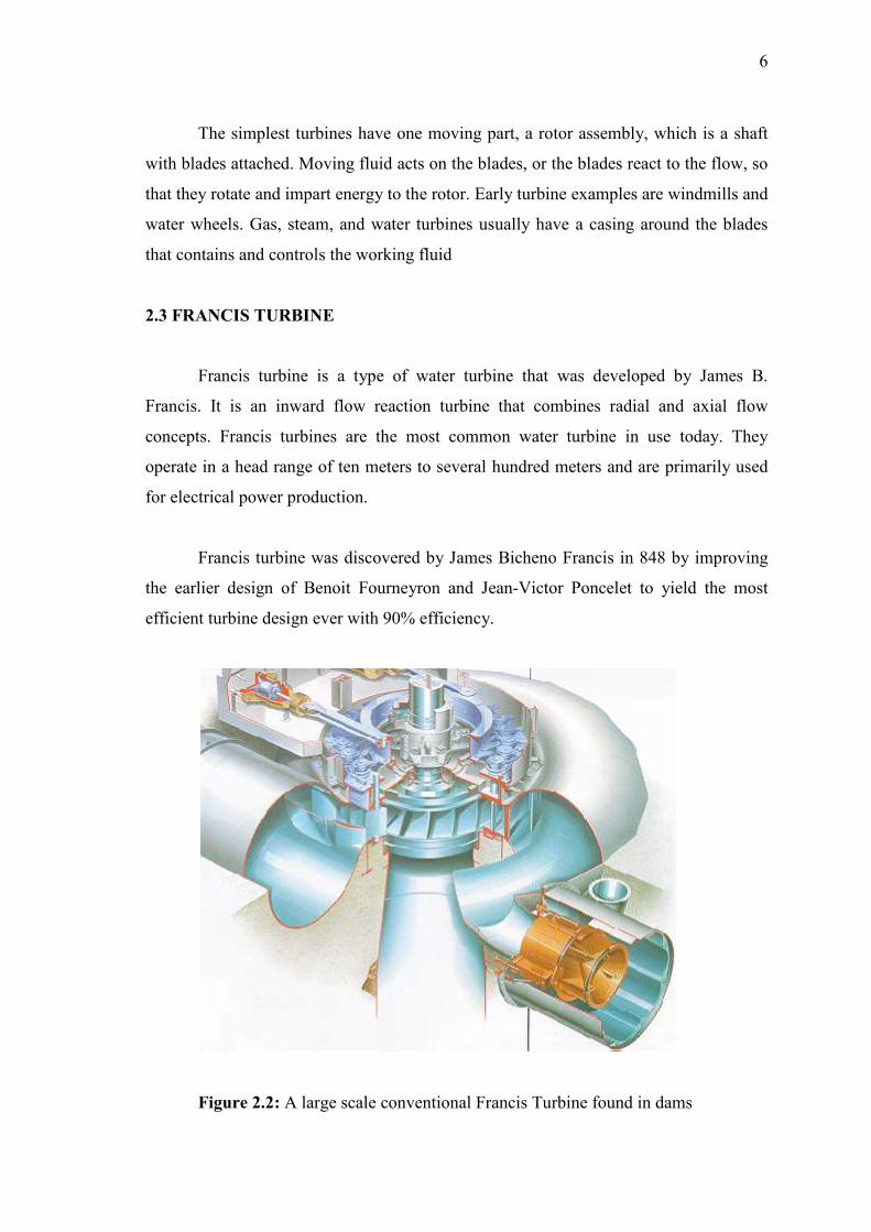
2.3 FRA�CIS TURBI�E
Francis turbine is a type of water turbine that was developed by James B.
Francis. It is an inward flow reaction turbine that combines radial and axial flow
concepts. Francis turbines are the most common water turbine in use today. They
operate in a head range of ten meters to several hundred meters and are primarily used
for electrical power production.
Francis turbine was discovered by James Bicheno Francis in 848 by improving
the earlier design of Benoit Fourneyron and Jean-Victor Poncelet to yield the most
efficient turbine design ever with 90% efficiency.
Figure 2.2: A large scale conventional Francis Turbine found in dams

7
2.4 REACTIO� TURBI�E
These turbines develop torque by reacting to the fluid's pressure or weight. The
pressure of the fluid changes as it passes through the turbine rotor blades. A pressure
casement is needed to contain the working fluid as it acts on the turbine stage or the
turbine must be fully immersed in the fluid. The body of the turbine contains and directs
the working fluid and, for water turbines, maintains the suction imparted by the draft
tube. Francis turbines and most steam turbines use this concept.
For compressible working fluids, multiple turbine stages may be used to harness
the expanding fluid usually gas efficiently. Newton's third law describes the transfer of
energy for reaction turbines. “Whenever a particle A exerts a force on another particle
B, B simultaneously exerts a force on A with the same magnitude in the opposite
direction. The strong form of the law further postulates that these two forces act along
the same line. This law is often simplified into the sentence, "To every action there is an
equal and opposite reaction."
2.5 CAVITATIO�S
Cavitations are the formation of vapor- or gas-filled cavities in liquids. If
understood in this broad sense, cavitations includes the familiar phenomenon of bubble
formation when water is brought to a boil under constant pressure and the effervescence
of champagne wines and carbonated soft drinks due to the diffusion of dissolved gases.
In engineering terminology, the term cavitations is used in a narrower sense,
namely, to describe the formation of vapor-filled cavities in the interior or on the solid
boundaries created by a localized pressure reduction produced by the dynamic action of
a liquid system without change in ambient temperature. Cavitations in the engineering
sense is characterized by an explosive growth and occurs at suitable combinations of
low pressure and high speed in pipelines; in hydraulic machines such as turbines,
pumps, and propellers; on submerged hydrofoils; behind blunt submerged bodies; and
in the cores of vertical structures.

8
This type of cavitations has great practical significance because it restricts the
speed at which hydraulic machines may be operated and, when severe, lowers
efficiency, produces noise and vibrations, and causes rapid erosion of the boundary
surfaces, even though these surfaces consist of concrete, cast iron, bronze, or other hard
and normally durable material.
Both experiments and calculations show that with ordinary flowing water
cavitations commences as the pressure approaches or reaches the vapor pressure,
because of impurities in the water. These impurities, called cavitations nuclei, cause
weak spots in the liquid and thus prevent it from supporting higher tensions. The exact
mechanism of bubble growth is generally described by mathematical relationships
which depend upon the cavitations nuclei.
Cavitations commences when these nuclei enter a low-pressure region where the
equilibrium between the various forces acting on the nuclei surface cannot be
established. As a result, bubbles appear at discrete spots in low-pressure regions, grow
quickly to relatively large size, and suddenly collapse as they are swept into regions of
higher pressure.
Figure 2.3: Example of cavitations in Francis Turbine

9
2.6 EFFICIE�CY
The efficiency rated on a Francis Turbine is considered to be mechanical since
the operating principle of a Francis Turbine includes the concept of simple mechanical
structures such as the water hitting the runner will cause the runner to spin and at the
same time rotating the shaft connecting the dynamo (in the case of a damp) to the
turbine. This principle of energy transfer through the rotating of shaft is identified as
mechanical hence evaluating the efficiency as mechanical.
In physics, mechanical efficiency is the effectiveness of a machine and is
defined as:
���ℎ������ ��������� =���� ���������� �����
(2.1)
Mechanical Efficiency is the ratio of work input to work output. It is often
expressed as a percentage. The efficiency of an ideal machine is 100 percent but an
actual machine's efficiency will always be less than 100% because of the Second law of
thermodynamics which states that the quality of energy will decay, eventually becoming
heat. This means that some of the work put into the system is transformed (lost) into
thermal energy (heat). In a mechanical system, friction is the most common cause of the
work lost to heat.
The actual mechanical advantage of a system is always less than the ideal
mechanical advantage due to these losses. Another way to express mechanical
efficiency is it is the ratio of actual mechanical advantage to ideal mechanical
advantage. In Francis Turbine case, the efficiency is the ratio of the power output or the
braking force, to the water power entering the turbine.

10
2.7 RU��ER
In a Francis Turbine, the runner is the part of the turbine which is connected
directly to the shaft of the turbine which is then normally connected to the dynamo. The
runner consists of several small blades or fins which accepts and enhances the energy
transfer from moving water to the shaft. The runner then, with the help of this blades
spins based on the water flows energy which is successfully transferred to runner.
Figure 2.4: CAD model of the Gunt Hamburg Francis turbine runner
Since a Francis Turbine is inward flow reaction turbine, the runner is located at
the centre at the turbine with a small cylindrical rod with curved sides at the very centre
of the turbine which helps the water flow out of the turbine after their energy is
transferred via the runner to the shaft. The water usually enters the runner at an angle
somewhat tangential to the blades on the runner to gather the most energy from the
flowing water. The runner of a Francis Turbine is said to be the most efficient turbine
design up to date.

11
2.8 GUIDI�G VA�ES
The guiding vanes of a Francis Turbine are curved aerofoil-like parts of the
Francis Turbine which normally placed at a certain distance away from the runner and
consist of several parts which surrounds the runner. These vanes are used mainly for
two reasons. The first is to guide the flowing working fluid to the runner and to control
the angle of entrance so that cavitations will be reduced or eliminated.
Figure 2.5: CAD model of the Gunt Hamburg Francis turbine guiding vanes and
its position on the Francis Turbine
The vanes are placed so that the flowing water which enters the turbine is
redirected into the passage created by the vanes. Water that flows within the Francis
Turbine are classified as turbulent which mean their flows are highly unsteady and
violent. It is the characteristic of this flow that cause the water inside the turbine to