modeling of double-angle connections for …
TRANSCRIPT

MODELING OF DOUBLE-ANGLE CONNECTIONS FOR ROBUSTNESS EVALUATION OF STEEL GRAVITY FRAMES
Jonathan M. Weigand
National Institute of Standards and Technology, Gaithersburg, MD 20899 USA [email protected]
Judy Liu
Oregon State University, Corvallis, OR 97330 USA [email protected]
Joseph A. Main
National Institute of Standards and Technology, Gaithersburg, MD 20899 USA [email protected]
ABSTRACT Component-based models of bolted double-angle beam-to-column connections have been developed for evaluating the structural robustness of steel gravity frames. The component-based models were developed based on results from high-fidelity finite-element models, which used solid elements to model the bolts, angles, and wide-flange sections, with explicit modeling of contact and friction. Fracture was modeled using element erosion with a plastic-strain-based failure criterion and reduced ductility at the “k-area” of the angle. The high-fidelity analyses were used to investigate the influence of span length on connection failure, including angle deformations at fracture. The component-based approach modeled each bolt row using a nonlinear load-displacement relationship that captured the effects of plastic hinge formation, straightening of the angle legs, and tearing of the angle near the heel. The component-based analysis results were compared with experimental data for double-angle connections subjected to combined rotation and axial extension representative of column loss scenarios.
INTRODUCTION Bolted double-angle beam-to-column connections are common in steel gravity framing systems and have demonstrated substantial deformation capacity in simulated column loss scenarios (Liu et al. 2012). Component-based connection models provide an efficient framework for modeling the behavior of connections under extreme loads by providing

automatic coupling between the in-plane flexural and axial connection behaviors, a feature that is essential for modeling connections under column removal. The computational efficiency of the component-based modeling approach makes it well suited for evaluating the robustness of entire buildings. This paper presents a component-based model for steel bolted-angle connections that was developed based on insights obtained from high-fidelity finite element analysis. Results from the high-fidelity analyses are first presented, including the influence of span length and observations on angle deformations at failure. The component-based modeling approach is then presented, and predictions of the model are compared to experimental data for bolted angle connections tested under a simulated column loss scenario.
HIGH-FIDELITY FINITE-ELEMENT MODELING
Modeling Approach The behavior of the bolted double-angle connections was first investigated using high-fidelity finite-element models, as illustrated in Figure 1, which were previously validated through comparisons with experimental data under axial loading and under a column removal scenario (Liu et al. 2012). The models were developed using the LS-DYNA finite-element software package (Hallquist 2007). The double angles, bolts, and wide-flange sections were modeled using 8-node solid elements with selective-reduced integration. The typical element size was about 2.6 mm (0.10 in) in the beam and column near the connecting elements and about 1.3 mm (0.05 in) in the bolts. The element size for the angles was on the order of 1.3 mm (0.05 in) to best capture plastic hinging mechanisms and fracture. The radius of the fillet at the heel of the angle was explicitly modeled. All components were initially in contact; static and dynamic friction coefficients of 0.3 were used.
Piecewise linear plasticity material models, calibrated to match data from tensile coupon tests, were used to model the steel. Finite element models of tensile coupons with appropriate gage length and element size were used to ensure that calculated engineering stress-strain curves corresponded to the test data. The plastic strain limit for each material (e.g., A36, A992) was calibrated to match the elongation at fracture from the tensile coupon tests. Element erosion, or removal of elements upon reaching an effective plastic strain limit, simulated fracture of the steel (Liu et al. 2012).
As proposed by Liu et al. (2012), the fracture strain in the heel of the angle was reduced to 60 % of the measured percent elongation for tensile coupons taken from the angle legs. This reduced the ductility at the critical location in the k-area, the region in the angle leg just past the fillet. The reduction in ductility at the k-area proposed by Liu et al. (2012) was based on comparisons to data from monotonic and cyclic tests of double-angle connections in tension (Garlock et al. 2003, Shen and Astaneh-Asl 1999). Reduced ductility in the k-area of an angle was also supported by coupon test data from Yang and Tan (2012). For W-shapes, Tide (2000) showed that percent elongation values at fracture were significantly smaller for coupons taken from the k-area than for coupons taken from
the web and flanges, because the k-area properties were affected by the rotary straightening process conducted in the mill. It has been acknowledged (Rees-Evans 2011) that rotary straightening and cold-working of steel angles could similarly result in reduced ductility in the k-area of the angles.
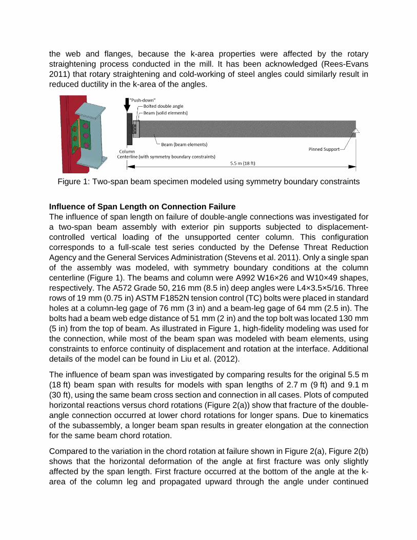
Figure 1: Two-span beam specimen modeled using symmetry boundary constraints
Influence of Span Length on Connection Failure The influence of span length on failure of double-angle connections was investigated for a two-span beam assembly with exterior pin supports subjected to displacement-controlled vertical loading of the unsupported center column. This configuration corresponds to a full-scale test series conducted by the Defense Threat Reduction Agency and the General Services Administration (Stevens et al. 2011). Only a single span of the assembly was modeled, with symmetry boundary conditions at the column centerline (Figure 1). The beams and column were A992 W16×26 and W10×49 shapes, respectively. The A572 Grade 50, 216 mm (8.5 in) deep angles were L4×3.5×5/16. Three rows of 19 mm (0.75 in) ASTM F1852N tension control (TC) bolts were placed in standard holes at a column-leg gage of 76 mm (3 in) and a beam-leg gage of 64 mm (2.5 in). The bolts had a beam web edge distance of 51 mm (2 in) and the top bolt was located 130 mm (5 in) from the top of beam. As illustrated in Figure 1, high-fidelity modeling was used for the connection, while most of the beam span was modeled with beam elements, using constraints to enforce continuity of displacement and rotation at the interface. Additional details of the model can be found in Liu et al. (2012).
The influence of beam span was investigated by comparing results for the original 5.5 m (18 ft) beam span with results for models with span lengths of 2.7 m (9 ft) and 9.1 m (30 ft), using the same beam cross section and connection in all cases. Plots of computed horizontal reactions versus chord rotations (Figure 2(a)) show that fracture of the double-angle connection occurred at lower chord rotations for longer spans. Due to kinematics of the subassembly, a longer beam span results in greater elongation at the connection for the same beam chord rotation.
Compared to the variation in the chord rotation at failure shown in Figure 2(a), Figure 2(b) shows that the horizontal deformation of the angle at first fracture was only slightly affected by the span length. First fracture occurred at the bottom of the angle at the k-area of the column leg and propagated upward through the angle under continued

loading. While the angle’s horizontal deformation at complete fracture increased somewhat with decreasing span, the angle’s deformation at first fracture was nearly constant, with values of 37 mm (1.5 in), 34 mm (1.3 in), and 35 mm (1.4 in) for span lengths of 2.7 m (9 ft), 5.5 m (18 ft), and 9.1 m (30 ft), respectively. This consistency in the angle’s deformation at fracture supported the use of a component-based modeling approach with a consistent value of angle deformation at failure, regardless of the span length. In the component-based approach, complete fracture of the connection is represented by successive fracture of each component in the connection, which allows the chord rotation at complete fracture to vary with span length as shown in Figure 2(b).
Figure 2: (a) Horizontal reactions versus chord rotation for different beam spans;
(b) average horizontal deformation of angle versus chord rotation
Geometry of Deformed Angle Figure 3 shows the geometry of a single angle in plan view, obtained from a high-fidelity finite element model in which the column leg and the beam leg of the angle were truncated at the centerlines of the column-leg bolts and the beam-leg bolts, respectively, and the angle was idealized as fully fixed at these cross sections. Figure 3(a) shows the initial, undeformed geometry of the angle, where k is the distance between the angle heel and the toe of the angle radius, gc is the column gage length of the angle (i.e., distance between the angle heel and the centerline of the column-leg bolt), gb is the beam gage length of the angle (i.e., distance between the angle heel and the centerline of the beam-leg bolt), and t is the angle thickness. Figure 3(b) shows the deformed geometry of the angle, in which the angle deformation along the beam axis,δ , is measured from the column face to the deformed position of the angle heel. The angle lengthens and straightens as it deforms, with two plastic hinges forming in the column leg, as indicated in Figure 3(b). This results in lateral deformation of the beam leg, δ ′ , and curvatures γ and γ ′ at the ends of the k-area in the column and beam legs, respectively. As is discussed subsequently, results of the high-fidelity analyses allowed relationships to be established between the curvatures and strains at the k-area, enabling the development of the component-based model.
-100
-50
0
50
100
150
200
250
300
350
0 0.04 0.08 0.12 0.16
Horiz
onta
l Rea
ctio
n (k
N)
Chord Rotation (radians)
5.5 m span (original)2.7 m span9.1 m span
0
10
20
30
40
50
60
0 0.045 0.09 0.135 0.18
Aver
age
Horiz
onta
l Def
orm
atio
n,
Bott
oms o
f Ang
les (
mm
)
Chord Rotation (radians)
5.5 m span2.7 m span9.1 m span
First fractureComplete fracture
(a) (b)

Figure 3: Angle geometry: (a) initial; (b) deformed.
COMPONENT-BASED CONNECTION MODEL Component-based connection models provide a versatile analytical framework that can be used to model the responses of connections under extreme loads, such as column removal. In the component-based model described in this paper, the connection is discretized into multilinear component springs that are assembled into a configuration representing the geometry of the connection (Figure 4), where each component spring embodies an isolated characteristic-width segment of the two angles.
Figure 4: Discretization of bolted angle into characteristic-width angle-segments
Load-Deformation Relationship As illustrated in Figure 5, the nonlinear behavior of the angle segment is represented through a piecewise-linear relationship between the axial load P and the angle deformation δ (see Figure 3). A single angle is considered with a component width b obtained by dividing the total depth of the angle by the number of bolts. The load
Pkk
tgb
gc
(a) (b)
δ ′δ
γγ ′
plastic hinges
heel
beam legco
lum
n le
g
column bolt CL
beam
bol
t CL
k-area

corresponding to one bolt row of a double-angle connection is obtained by doubling P. The yield capacity Py corresponds to formation of plastic hinges in the column leg of the angle, and the ultimate capacity Pu is associated with fracture of the angle at the k-area.
Figure 5: Load-deformation relationship for angle
Plastic Hinge Formation at Yield Load The yield load, corresponding to the formation of two plastic hinges in the column leg of the angle (Figure 3(b)) is given by
= py
eff
2
MP
g, (1)
where Mp = (bt 2 / 4)Fy is the plastic moment capacity of the component-width angle segment, Fy is the yield strength of the angle, geff = gc – k – dh ∕ 2 is the effective gage length of the angle’s column leg after formation of the plastic hinges (i.e., the distance between the plastic hinges), and dh is the diameter of the column-leg bolt holes. The angle deformation at the formation of the plastic hinges, δy, can be calculated as
δ = yy
i
PK
, (2)
where Ki is the initial stiffness of the angle segment. The initial stiffness is calculated from the following expression, which was derived by Shen and Astaneh-Asl (2000) based on the geometry of the section of angle between the beam-leg bolt and the column-leg bolt, assuming elastic bending of the angle’s column leg:
= − + b
i 3c c b
312 14( )
gEIKg g g
, (3)
where E is the modulus of elasticity of steel and I = bt 3 ∕ 12 is the moment of inertia of the angle.
Deformation, δ
Load
, P
Pu
Py
δy δu δf

Angle Fracture at Ultimate Load Expressions for the ultimate load Pu (i.e., the load corresponding to initial tearing in the angles) and the corresponding angle deformation δu are derived based on the simplified geometry shown in Figure 6, in which the angle’s column leg is modeled as a straight-line segment with concentrated plastic hinges at its ends, subjected to axial tension Tu, shear force Vu, and bending moment Mu. The plastic hinge lengths are assumed equal to the angle thickness t.
Figure 6: Two-hinge idealization of the angle’s column leg at the ultimate load:
(a) geometry and (b) free-body diagram.
Equilibrium of forces along the beam axis yields the following expression for Pu:
θ θ= +u u u u ucos sinP V T , (4)
in which the chord rotation of the angle’s column leg, θu, can be calculated as
δθ
δ−
∗
′− −= − +
1 c uu
c u
cos g tg t
, (5)
where δ ∗u is the elongation of the column leg at the ultimate load. The shear and axial
tension in the angle’s column leg are calculated as
α=u yV P and α=u y / 3T btF , (6a,b)
in which α = 1.2 is a strain-hardening coefficient. The expression for Tu in Eq. (6b) assumes that the cross-section is fully yielded with a linear strain profile based on observations from high-fidelity models, in which the tensile and compressive strains at the faces of the angle’s column leg at fracture (at the toe of the angle radius) were found to be εuk and 1
2 εuk , respectively, where εuk is the elongation at fracture at the k-area. This observed strain profile can be decomposed into a bending strain of 3
4 εuk and an axial strain of 1
4 εuk , from which the column-leg elongation can be calculated as δ ε∗ = 1u uk2 t ,
gc − t − gc − t +
δ ′u
δu
θu
Tu
Vu
Mu
θu
Vu
Tu
Mu
(a) (b)
δ ∗u

assuming that axial elongation occurs only at the plastic hinges, with plastic hinge lengths of t. As proposed by Liu et al. (2012), in the absence of test data for the k-area, 60 % of the reported elongation from certified mill test reports or tests of coupons from the leg of the angle is recommended for εuk .
The lateral deformation of the beam leg, uδ ′ in Eq. (5), is calculated from the geometry:
γδ γ′ ′= − − ≈ −′ −b u bu u( )sin( ( ) / 2) ( )( ) / 2g t k t g t k t . (7)
Based on the observed strain profile at the ultimate load, noted above, the curvature of the angle’s column leg at the end of k-area can be calculated as
εγ = uk
u32t
. (8)
The curvature of the angle’s beam leg at the end of the k-area, uγ ′ in Eq. (7), can be related to the curvature of the angle’s column leg, uγ in Eq. (8), through the following empirical equation, based on the results of high-fidelity finite-element analyses (to be published):
( )( )γ γ ′ = + − − + − −3 5 25 5u u 16 16/ 1 ( 1)( )r r t r t , (9)
where r = gc ∕ gb is the ratio of the angle’s gage lengths. Eq. (9) is considered to be applicable for thickness, t, from 6.4 mm (0.25 in) to 15.9 mm (0.63 in), and gages, gb and gc, from 51 mm (2.0 in) to 76 mm (3.0 in). Also, gc should be greater than or equal to gb. The ultimate deformation of the angle can be calculated from the geometry as
( )δ δ θ= − −u c b utang t . (10)
The failure deformation, at which the load P drops to zero, is taken as δf = 1.1δu.
Comparisons with Experimental Data Results of the component-based connection model were compared with experimental measurements from bolted-angle connection tests reported by Weigand and Berman (2015). In that study, the connections were tested under combined rotation and axial deformation demands representative of a column loss scenario, corresponding to displacement-controlled vertical loading of an unsupported center column in a two-span beam assembly. The double-angle connections at both ends of each beam span were assumed to be identical, and the end columns were assumed to be fixed, so that all deformations occurred in the connections and beams. In the component-based modeling, a single beam span was considered, assuming symmetry of the response about the unsupported center column. The load-deformation relationship for single-plate shear connections from Main and Sadek (2014) was used for the compressive response of the connections, with yield and ultimate capacities corresponding to the combined bearing strength at the bolt holes of the two angles’ beam legs.

Figure 7 shows a comparison of measured and computed values of the vertical load applied to the unsupported center column and the horizontal reaction at the end column for a double-angle connection with three bolt rows (Weigand and Berman 2015, specimen ba3b|34|14). For that connection test, the thickness of the angles was t = 6.4 mm (0.25 in) and the gages of the column leg and the beam leg were gc = 76 mm (3.0 in) and gb = 70 mm (2.8 in), respectively. The measured yield strength of the angle steel was Fy = 382 MPa (55.4 ksi). Initial differences between the measured and computed values, for displacements less than about 300 mm (11.8 in), resulted from frictional resistance of the connection due to pre-tensioning of the bolts, which was not considered in the model. The subsequent response, after frictional slippage and loss of pre-tension, is captured fairly well by the component-based model. The peak vertical load and the peak horizontal reaction from the model exceed the measured values by 9 % and by 0.7 %, respectively. The model prediction for the center column displacement at the ultimate vertical load was 7 % less than the experimental value.
Figure 7: Comparisons of component-based model with experimental measurements
for a double-angle connection with three bolt rows (estimated uncertainty in experimental data is less than ±0.5 %, based on repeated calibrations of instruments)
CONCLUSIONS Building on insights obtained from high-fidelity finite element analyses of bolted double-angle connections, a component-based model was developed to capture the response of the connections under the combined axial and flexural loading that occurs in column removal scenarios. The high-fidelity modeling provided key insights on the initiation of angle fracture at a consistent level of deformation and the relationship between strains and curvatures in the angle at the point of fracture. By considering the mechanics of angle deformation associated with the formation of two plastic hinges in the column leg of the angle, equations were developed for the yield capacity and the ultimate capacity of the angle, along with the corresponding deformations. Using these equations, a nonlinear load-displacement relationship was defined to represent the axial response for each bolt row of the angle. Predictions of the component-based model were compared with experimental results for a bolted double-angle connection under a column removal scenario, showing that the model captured the key features of the measured response.
0
10
20
30
40
0 250 500 750 1000 1250 1500
Verti
cal L
oad
(kN
)
Vertical Displacement of Center Column (mm)
Weigand and Berman (2015):specimen ba3b|34|14Component-based model
-50
0
50
100
150
200
250
300
0 250 500 750 1000 1250 1500
Hor
izon
tal R
eact
ion
(kN
)
Vertical Displacement of Center Column (mm)
Weigand and Berman (2015):specimen ba3b|34|14Component-based model

ACKNOWLEDGMENTS This study was partially supported by the NIST/ UMD-ARRA Fellowship. The authors would like to thank Fahim Sadek of NIST for valuable comments and input on this work.
DISCLAIMER Certain commercial software or materials are identified to describe a procedure or concept adequately. Such identification is not intended to imply recommendation, endorsement, or implication by NIST that the software or materials are necessarily the best available for the purpose.
REFERENCES Garlock, M.M., Ricles, J.M., and Sause, R. (2003). “Cyclic Load Tests and Analysis of Bolted Top-and-Seat Angle Connections,” J. Struct. Eng., Vol. 129, Issue 12, pp. 1615-1625.
Hallquist, J. (2007). LS-DYNA Keyword User’s Manual, Version 971, Livermore Software Technology Corporation, Livermore, CA.
Liu, J., Main, J. and Sadek, F. (2012) “Modeling of Double-Angle Shear Connections for Evaluation of Structural Robustness,” Proc., 6th Congress on Forensic Engineering, San Francisco, CA, October 31 – November 3, 2012, pp. 1081 – 1090.
Main, J.A. and Sadek, F. (2014). “Modeling and Analysis of Single-Plate Shear Connections under Column Loss,” J. Struct. Eng, 04013070, pp. 1-12.
Rees-Evans, D. (2011). “Re: Steel Angle Question,” message to J. Liu, 27 Sept. 2011, e-mail.
Shen, J. and Astaneh-Asl, A. (1999) “Hysteretic Behavior of Bolted-Angle Connections,” J. Constructional Steel Research, Vol. 51, pp. 201–218.
Stevens, D., Crowder, B., Sunshine, D., Marchand, K., Smilowitz, R., Williamson, E., and Waggoner, M. (2011). “DoD Research and Criteria for the Design of Buildings to Resist Progressive Collapse,” J. Struct. Eng., Vol. 137, Issue 9, pp. 870-880.
Tide, R.H.R. (2000) “Evaluation of Steel Properties and Cracking in ‘k’-area of W Shapes,” Engineering Structures, Vol. 22, Issue 2, pp. 128-134.
Weigand, J. M. and Berman, J. W. (2015) “Integrity of Bolted Angle Connections Subjected to Simulated Column Removal,” J. Struct. Eng., 04015165, pp. 1-13.
Yang, B. and Tan, K.H. (2012) “Numerical Analyses of Steel Beam-Column Joints Subjected to Catenary Action,” J. Constructional Steel Research, Vol. 70, pp. 1–11.