modeling instructions for designing prefabricated elements · modeling instructions for designing...
TRANSCRIPT

BEC 2012
Modeling instructions for designing prefabricated elements
Betoniteollisuus ry February 2012
BEC2012 2 (38)
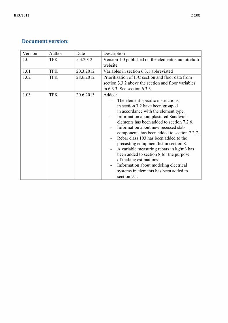
Document version:
Version Author Date Description 1.0 TPK 5.3.2012 Version 1.0 published on the elementtisuunnittelu.fi
website 1.01 TPK 20.3.2012 Variables in section 6.3.1 abbreviated 1.02 TPK 28.6.2012 Prioritization of IFC section and floor data from
section 3.3.2 above the section and floor variables in 6.3.3. See section 6.3.3.
1.03 TPK 20.6.2013 Added: - The element-specific instructions
in section 7.2 have been grouped in accordance with the element type.
- Information about plastered Sandwich elements has been added to section 7.2.6.
- Information about new recessed slab components has been added to section 7.2.7.
- Rebar class 103 has been added to the precasting equipment list in section 8.
- A variable measuring rebars in kg/m3 has been added to section 8 for the purpose of making estimations.
- Information about modeling electrical systems in elements has been added to section 9.1.

BEC2012 3 (38)
Table of Contents Foreword 5 1 Introduction 5 2 Glossary of Terms 5 3 Handover of Models 6
3.1 Agreements 6 3.2 Handing Over the Model in Original Format 6 3.3 Handing Over IFC Models 7
3.3.1 IFC building part 7 3.3.2 IFC section and floor 8
3.4 Utilizing the Model 9 4 Design Requirements 10
4.1 Kickoff Meeting 10 4.2 Accuracy definitions for each design phase 10
4.2.1 General design (TELU08-RAK C4) 10 4.2.2 Acquisition-driven design (TELU08-RAK C6) 10 4.2.3 Implementation design (TELU08-RAK C7) 11
4.3 Preparing Several Structural Models 11 5 General information about modeling concrete elements 12 6 Basic Information about the Elements 15
6.1 GUID Identifier 15 6.2 Numbering and Naming 15 6.3 Other basic information about the elements 17
6.3.1 Design life, stress class, fire resistance rating 17 6.3.2 Product group information 18 6.3.3 Section and floor information 18 6.3.4 Other information about the elements 19
7 Quantity Information and Tabling 20 7.1 General 20 7.2 Modeling by Element Type and Reporting 20
7.2.1 Beam types 21 7.2.2 Column types 22 7.2.3 Single-skinned wall element types 23 7.2.4 Massive slab types 24 7.2.5 Balcony slabs 25 7.2.6 Sandwich-type elements 26 7.2.7 Hollow-core slab types 28
8 Modeling Casting Equipment and Producing Tables 30 8.1.1 Openings and recesses: 36
9 Electrical Equipment for Elements 37 9.1 Electrical Modeling 38
10 Designing Opening Reservations Based on the Information Model 38 10.1 Process for Preparing Opening Drawings 40

BEC2012 4 (38)
11 Annotations for Design Status and Date 41 11.1 Designs 41 11.2 Fabrication 42 11.3 Delivery 43 11.4 Erection 44 11.5 Model publication date 44
12 Drawings 45

BEC2012 5 (38)
Foreword During the BEC 2012 project, which took place in 2011 and 2012, Tekla Corporation worked with partners from the concrete prefabrication industry and structural designers to develop a solution for the 3D design of prefabricated concrete elements, information modeling, and data transfer. These modeling instructions were drafted by Tero Kautto from Finnmap Consulting Oy.
1 Introduction The BEC 2012 instructions are intended to define certain ground rules concerning information modeling for prefabricated concrete elements. All modeling consultants should comply with these instructions. It was not the intention to define specific tools that must be used for specific parts of each model. Instead, the approach was to define the content of the model. If these instructions are complied with, models should be similar regardless of the design bureau or modeler.
Models must have consistent content to enable them to be effectively utilized. The entire project can benefit when models can be directly utilized. If the only material available is a traditional 2D drawing, a considerable amount of the model's information and benefits will go unused. Precast fabrication industry requires models made in the same manner to enable element lists, equipment lists, and data transfer to be reliably implemented directly from the model. Similarly, construction sites have specific requirements for the model to enable it to be used for site management and other purposes. Each section in these instructions begins by setting out general requirements before providing more detailed instructions based on the functionality of the Tekla Structures software.
2 Glossary of Terms BIM = Building Information Modeling: an information model. IFC = Industry Foundation Classes: an international standard for transferring information about products used in building modeling Tekla Structures = an information modeling application produced by the Tekla software corporation to aid in building design. The Tekla Structures software is referred to in these instructions as TS. Cast Unit = a concrete element in the TS software Rebar = a reinforcing bar in the TS software UDA = User-Defined Attribute: metadata to be provided in the TS software Component = a tool to aid modeling Custom Component = functionality in the TS software to enable the user to create his/her own components. Original Format = the software's own storage format. ACN = Assembly Control Number: a unique running number used in TS.
BEC2012 6 (38)
3 Handover of Models Utilizing the model for more than simply creating drawings is beneficial to the entire project. Designers can hand the model over to the precast fabrication industry, subcontractors, and other parties involved in the project. Depending on the use case, the model is handed over in IFC format and/or the software's original format in accordance with the project's schedule.
3.1 Agreements The design agreement should contain terms governing the handover of the information model to other parties involved in the project. If no such terms exist, a separate handover agreement should be drafted. The agreement should cover the following matters:
- The contracting parties - Basic information about the project - An itemization of the material to be handed over. For example: an IFC
model (in 2x3 format) and/or a model in the software's original format (TS V17).
- The design agreement may contain precise definitions of the model's scope and accuracy. This may be based on the General Requirements for Information Models.
- Updates to the model and the schedule for such updates. - User rights and ownership rights for the model, with a description
of the rights and the period for which the rights are assigned. - Handover of the model to third parties. - Further utilization of the model on other sites. - References to separate instructions or information model specifications
containing information that is required for the model to be utilized. - Order of precedence of the model and drawings. - Payments, payment terms, contractual penalties. - Business secrets and professional secrets. - General contractual terms (reference to the General Conditions
for Consulting (known as KSE in Finland)). - Archiving.
3.2 Handing Over the Model in Original Format If the model is to be sent in original format, the profile libraries and similar files used in the model must also be sent.
TS instructions If an original Tekla Structures model is to be sent, the following files must be sent:
- To be sent: o *modelname*.db1 (the model) o profdb.bin (profile database) o profitab.inp (parametric profile definitions) o matdb.bin (material database) o rebar_database.inp and mesh_database.inp (rebar databases)
BEC2012 7 (38)
o assdb.db and screwdb.db (bolt databases) o Any custom-made profiles that are used in the model
should also be handed over Sketch profiles (the model's xslib.db1 file, either in its
entirety or with non-publishable components removed) Other parametric profiles (*.clb files)
o Guidelines on the aforementioned files' locations within the TS environment
o Information model specifications
- The following parts of the handover may be subject to separate agreement:
o Drawing files *.dg (Drawings are normally sent in PDF format or in the format agreed on for the project)
o Custom components xslib.db1 (see the point on sketch profiles above)
o Other custom settings
3.3 Handing Over IFC Models IFC models are often used to ensure compatibility between different design disciplines, for quantity surveying, and for other similar purposes. For this reason, IFC models must be built in accordance with the IFC standard.
3.3.1 IFC building part
The structural designer must ensure that the building parts are correct in the IFC model: walls should be defined as walls and beams should be defined as beams. The software normally does this automatically if the structures are modeled using the tools specifically intended for each element in question: walls are modeled using the wall tool, beams are modeled using the beam tool, etc.
TS instructions TS offers modelers considerable freedom, meaning that structural elements may not always be modeled using the tools designed for them. For example, hollow-core slabs are modeled using the beam tool rather than the slab tool. To ensure that hollow-core slabs are categorized as slabs in the IFC model, the IFC entity must be changed to IfcSlab in the user-defined-attributes field.
BEC2012 8 (38)
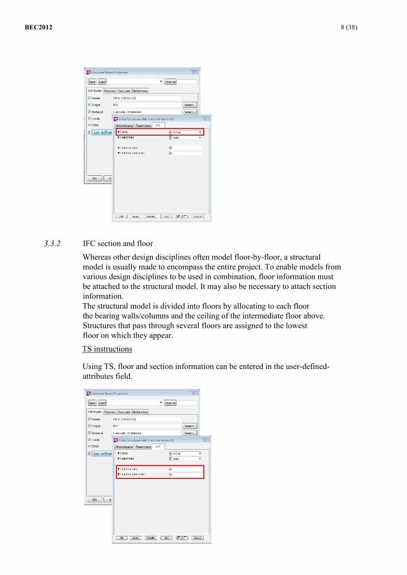
3.3.2 IFC section and floor
Whereas other design disciplines often model floor-by-floor, a structural model is usually made to encompass the entire project. To enable models from various design disciplines to be used in combination, floor information must be attached to the structural model. It may also be necessary to attach section information. The structural model is divided into floors by allocating to each floor the bearing walls/columns and the ceiling of the intermediate floor above. Structures that pass through several floors are assigned to the lowest floor on which they appear.
TS instructions
Using TS, floor and section information can be entered in the user-defined-attributes field.

BEC2012 9 (38) 3.4 Utilizing the Model
When an agreement has been drafted on how the models will be utilized, they can be distributed to the parties involved in the project.
Models may simultaneously contain elements in the implementation phase and elements in the drafting phase, so it will not be possible to retrieve data of the same quality on all of the elements. To make best use of the information in the model it is therefore essential to know the design status of each element (see chapter 11).
Precast fabrication industry has varying abilities to utilize modeling information. However, every party aims to extract reliable quantity information directly from the model. With this as a foundation, it becomes simpler to begin integrating automatic data transfer into manufacturing execution systems and into fabrication. The quantity information provided by the model also enables designers to prepare fabrication drawings at a later stage.
Construction sites may use the model for scheduling, managing logistics, or site organization. The model enables the construction site's installation schedule to be transmitted to the element fabrication plant and the designer, which facilitates the scheduling of fabrication and design.
Agreements must be made for each project on how information will be transferred to new design models if the construction site or element prefabrication plant adds information to the model.

BEC2012 10 (38)
4 Design Requirements Unless otherwise agreed, the designers must comply with these instructions, as well as the accuracy levels, data transfer procedures, and collaboration defined in the Common BIM Requirements 2012.
4.1 Kickoff Meeting At the beginning of the project, a kickoff meeting should be arranged to enable the information modeling objectives to be agreed. It is also recommended that a meeting be arranged whenever new parties become involved in the project. Parties such as subcontractors or the precast fabrication industry may have their own needs as regards modeling. The following matters should be discussed and/or agreed on during the kickoff meeting:
- The matters set out in the BEC 2012 information modeling instructions and the Common BIM Requirements 2012.
- Each party must nominate personnel who are responsible for information modeling and their contact details must be recorded - Applications and versions
- Characteristics of the object: building, section, floor, job, etc. - Finetuning modeling accuracy in accordance with information needs
based on these instructions and the Common BIM Requirements 2012 - Order of precedence among the model and drawings. - Agreeing on
annotations for the elements' design status and date - Numbering the prefabricated elements and using assembly control numbers (ACNs) in TS.
- If the structural model is divided into several models and/or organizations, an agreement must be made on the ground rules and procedures for exchanging information - Further work connected with modeling.
- Agreeing on how information added by the precast fabrication industry and subcontractors will be transferred to an updated design model
- Designing opening reservations based on the information model, preparing drawings, and assigning responsibility
- Agreeing on the publication formats and schedule for the models - Drafting handover agreements that cover the information models - Using information model specifications
4.2 Accuracy definitions for each design phase 4.2.1 General design (TELU08-RAK C4)
Prefabricated elements should be modeled in accordance with preliminary designs to ensure that they are correctly sized and in the correct place in terms of base geometry. This enables the model to be used for preliminary quantity surveys and design coordination.
4.2.2 Acquisition-driven design (TELU08-RAK C6)
Models designed with an acquisition-driven approach are developed to the extent required for acquisition inquiries to enable requests for quotations to be drafted.

BEC2012 11 (38)
Acquisition inquiries will require sample elements and drawings to be drafted for some of the prefabricated elements. The sample elements must be modeled to the same degree of accuracy as in the implementation design.
The basic information and geometry data for the other elements must be provided in sufficient detail to ensure that the element reports obtained from the model contain the basic information and quantity data required by the concrete precast fabrication industry as stipulated in these instructions. Chapters 6 and 7 describe quantity data and basic information.
A decision must be made for each project on modeling surface treatments for all facade elements and on providing rebar estimates for the elements.
4.2.3 Implementation design (TELU08-RAK C7)
During the implementation design phase, further information is provided to ensure that the elements meet the same standards of information content as traditional drawings. All necessary information about the elements is added to the model either by modeling or by adding text. Examples:
- The precise geometry of the concrete is modeled, including beveling, although information about the beveling facets must be added in text form.
- Equipment that must be measured to a specific location must be modeled. If any equipment is not modeled, such as trusses, the information must be added to the elements and reported on in the same manner as for modeled equipment.
4.3 Preparing Several Structural Models Depending on the size of the project, the structural designer may need to divide the project into several models. Similarly, several different organizations may be involved in modeling the project's structures, in which case the structures will belong to different models. For example, a project may have a head structural designer and a separate prefabricated element designer. There may be numerous similar needs. Models can be handed over to design organizations in accordance with section 3, but technical limitations currently make it difficult to frequently combine separate models to create a single model in original format. However, separate structural models can be combined using the IFC format. It is important to agree on the ground rules for modeling, interface inspections, and any additional work involved in modeling, such as the following:
- Combining models
- Ensuring that the head structural designer's model contains the most up-to-date basic information and geometric data on the prefabricated elements

BEC2012 12 (38)
5 General information about modeling concrete elements Concrete elements must be modeled in such a way that reports can be generated containing the information required by the precast fabrication industry. Element modeling must be consistent and similar for each type of element. Each type of element may have its own definitions for tables and reports. The table below describes the basic information needed by the precast fabrication industry. The column on the right refers to the relevant section in this document. Additionally, any equipment required for the elements must be modeled in accordance with these instructions.
ELEMENT ID/DRAWING Section 6.2 ELEMENT TYPE ID Section 6.2 ELEMENT SERIAL NUMBER Section 6.2 PRODUCTION SERIAL NUMBER Section 6.2 NUMBER OF ELEMENTS Section 6.2 ID (GUID) Section 6.1 RUNNING NUMBER (ACN) Section 6.2 ERECTION SECTION Section 6.3.3 FLOOR Section 6.3.3 PRODUCT TYPE Section 6.3.2 LENGTH Section 7 HEIGHT Section 7 WIDTH Section 7 MAX. LENGTH Section 7 MAX. HEIGHT Section 7 MAX. WIDTH Section 7 THICKNESS INNER SKIN Section 7 THICKNESS INSULATION Section 7 THICKNESS OUTER SKIN Section 7 CONCRETE CLASS (INNER SKIN) Section 7 CONCRETE CLASS (OUTER SKIN) Section 7 STRESS CLASS (INNER SKIN) Section 6.3.1 STRESS CLASS (OUTER SKIN) Section 6.3.1 DESIGN LIFE Section 6.3.1 FIRE RESISTANCE RATING Section 6.3.1 SURFACE CLASSIFICATION Section 6.3.4 VOLUME (INNER SKIN) Section 7 VOLUME (OUTER SKIN) Section 7 MASS Section 7 GROSS AREA Section 7 NET AREA Section 7
BEC2012 13 (38)
SURFACE 1 OUTER SKIN Section 8 SURFACE 1 EXTERNAL SHELL (m2) Section 8 SURFACE 2 OUTER SKIN Section 8 SURFACE 2 OUTER SKIN (m2) Section 8 SURFACE 3 OUTER SKIN Section 8 SURFACE 3 OUTER SKIN (m2) Section 8 DRAWING DATE REVISION ID CHANGE DATE NOTES DESIGN STATUS Section 11 DESIGN SCHEDULE (DATE) Section 11
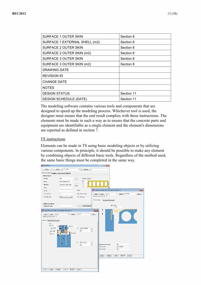
The modeling software contains various tools and components that are designed to speed up the modeling process. Whichever tool is used, the designer must ensure that the end result complies with these instructions. The elements must be made in such a way as to ensure that the concrete parts and equipment are identifiable as a single element and the element's dimensions are reported as defined in section 7.
TS instructions Elements can be made in TS using basic modeling objects or by utilizing various components. In principle, it should be possible to make any element by combining objects of different basic tools. Regardless of the method used, the same basic things must be completed in the same way.

BEC2012 14 (38)
Photo: The slab collections, the wire loop, and the basic bolt/column shoe components in TS. The element's concrete parts must have the precast setting selected to enable them to be distinguished from the other objects in the model and to ensure that the correct cast-unit level variables are used.
Photo: Precast variable in the wall tool
General modeling rules:
- If the element is made from several parts, ensure that the element's main part is the correct object.
- Always check that all of the concrete parts and equipment are connected to the element.
- The modeling direction affects the direction of the element identifiers in the installation pictures.
- If an element is to be cut lengthways (for example, if a hollow-core slab is being cut so that it becomes narrower), the line-cut tool should be used.
- Elements can be shortened using the fitting tool. - If the end of the element is to be inclined in two directions, the fitting
tool should be used first and the cut can be performed using the line-cut tool.
BEC2012 15 (38)
6 Basic Information about the Elements The elements in the model, along with the related information and equipment, must be identifiable. From the point of view of utilizing the model and enabling automatic data transfer, it is important that all designers use agreed definitions. The following sections define how the information set out below should be recorded in the model. ELEMENT ID/DRAWING ELEMENT TYPE ID ELEMENT SERIAL NUMBER
PRODUCTION SERIAL NUMBER NUMBER OF ELEMENTS ID (GUID) RUNNING NUMBER (ACN) ERECTION SECTION FLOOR PRODUCT TYPE STRESS CLASS (INNER SKIN) STRESS CLASS (OUTER SKIN) DESIGN LIFE FIRE RESISTANCE RATING
6.1 GUID Identifier Modeling software gives each part a unique GUID identifier. GUID identifiers enable the same part to be identified across different models. This linked data can be preserved when the model is updated. The data can also be transferred from one model to another. When adding data such as the installation date to elements, the GUID identifiers should be preserved by editing building parts that have already been created rather than deleting the parts and creating new ones to replace them.
6.2 Numbering and Naming In addition to automatic GUID identifiers, an element ID is also recorded for each element. The element ID typically consists of a type ID and a number. The elementtisuunnittelu.fi website contains a list of the identifiers that should be used. In addition to the element ID, each element must have its own unique ID, even if identical elements are present on the same fabrication drawings. The GUID identifier is rarely suitable for use as a unique identifier by the precast fabrication industry, so unique identifiers or running numbers must be defined by each software package.
The naming and numbering lists that are in use must be distributed to the project group to help them use the model optimally.
TS instructions In Tekla, this basic information can be found using the marked fields below. ELEMENT ID/DRAWING CAST_UNIT_POS

BEC2012 16 (38)
ELEMENT TYPE ID CAST_UNIT_PREFIX ELEMENT SERIAL NUMBER CAST_UNIT_SERIAL_NUMBER
PRODUCTION SERIAL NUMBER
Included in the CAST_UNIT_POS identifier, either as part of the CAST_UNIT_PREFIX information or as a consequence of the numbering scheme (in accordance with the Family numbering preferences)
NUMBER OF ELEMENTS NUMBER ID (GUID) GUID RUNNING NUMBER (ACN) MAINPART.ACN
The definitions of element IDs and type IDs for hollow-core slabs, fire performance slabs, recessed slabs, thin-shell slabs, and top-strand slabs are exceptions to the table above. All types of hollow-core slabs are defined in TS simply with the identifier "O", while thin-shell slabs have the identifier "KL". However, more precise definitions are provided for reports and lists using the slab profiles.
Photo: Hollow-core slab preferences in TS
ELEMENT ID/DRAWING PROFILE+"- -"+ CAST_UNIT_SERIAL_NUMBER
ELEMENT TYPE ID PROFILE
TS compares elements with each other when it generates the numbering scheme to group similar elements under the same numerical ID and different elements under different numerical IDs. The numbering policy develops as new elements are designed. This may cause the elements' numerical IDs to change several times during the design phase, making it complicated to keep track of elements. The IDs of element designs that have been sent for fabrication must not change unless an appropriate revision is made. Elements can be tracked in Tekla using the ACN number rather than the element ID. The ACN number is a unique running number that remains the same even if there are changes to the element ID and/or ID number of the drawing during the design phase. ACN numbers are added to elements at an agreed stage of the project. Unless otherwise agreed, designers will add ACN numbers before they begin drafting implementation drawings. It may also be agreed that ACN numbers can be
BEC2012 17 (38)
added during the acquisition-driven design phase. This would enable the element to be tracked throughout the entire project. When ACN numbers have been added, designers should take care to preserve the ACN numbers. If elements are removed and replaced with new ones, the old ACN number should be transferred to the new element.
The ACN number should appear on the drawings in addition to the element ID.
Photo: The unique ACN number is added to drawings in addition to the element ID.
6.3 Other basic information about the elements To enable information to be transferred directly from the model to manufacturing execution systems, certain basic details must be input in pre-agreed fields. These details are the design life, stress class, fire resistance rating, product group, section, and floor.
6.3.1 Design life, stress class, fire resistance rating
Information about the design life, stress class, and fire resistance rating should be added to concrete elements in such a way that the information can be read directly from the model and utilized in reports that can be printed on the model.
STRESS CLASS (INNER SKIN) STRESS CLASS (OUTER SKIN) DESIGN LIFE FIRE RESISTANCE RATING
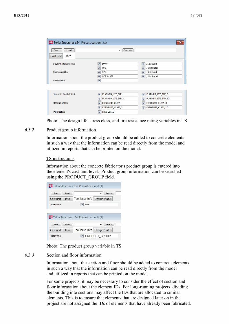
TS instructions The agreed basic information is entered into TS in the cast-unit level fields in accordance with the picture below. For elements that require only one variable, the greater of the design life and stress class variables is used.
BEC2012 18 (38)
Photo: The design life, stress class, and fire resistance rating variables in TS
6.3.2 Product group information
Information about the product group should be added to concrete elements in such a way that the information can be read directly from the model and utilized in reports that can be printed on the model.
TS instructions Information about the concrete fabricator's product group is entered into the element's cast-unit level. Product group information can be searched using the PRODUCT_GROUP field.
Photo: The product group variable in TS
6.3.3 Section and floor information
Information about the section and floor should be added to concrete elements in such a way that the information can be read directly from the model and utilized in reports that can be printed on the model. For some projects, it may be necessary to consider the effect of section and floor information about the element IDs. For long-running projects, dividing the building into sections may affect the IDs that are allocated to similar elements. This is to ensure that elements that are designed later on in the project are not assigned the IDs of elements that have already been fabricated.

BEC2012 19 (38)
TS instructions Unless otherwise agreed for the project, section and floor information is defined using IFC variables (see section 3.3.2).
If the precast fabrication industry's section and floor definitions differ from those of the subcontractor, a project-specific agreement may be made to add the section information to the BLD_SECTION variable and the floor information to the BLD_FLOOR variable. Other methods are also possible.
If the BLD_SECTION and BLD_FLOOR fields are used, the section and floor information should be entered into the element's cast-unit level.
Photo: The section and floor information variables in TS If the designer wishes to divide the building into sections using a method not described above, a separate agreement should be made. This may be necessary due to the length of the project or the nature of the software.
The following alternatives are available: - The element's prefix and/or start number fields, e.g., Prefix K and
StartNumber 2700 (a beam in section 27) - The User-defined-attribute field can be used to specify numbering - The Finish field
6.3.4 Other information about the elements
Any other information related to fabricating the elements, such as the surface class, the grain size, and the hoisting strength, can be input in the free-form fields.
BEC2012 20 (38)
7 Quantity Information and Tabling
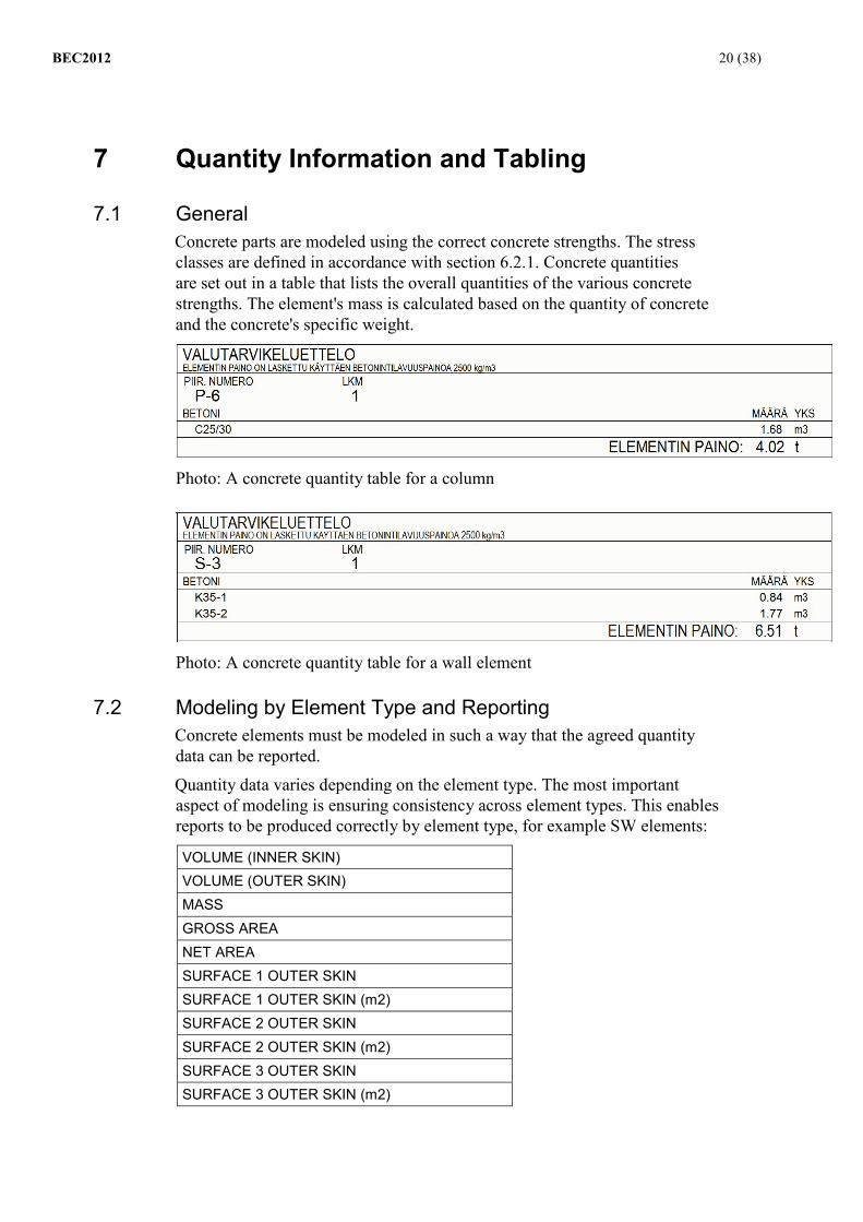
7.1 General Concrete parts are modeled using the correct concrete strengths. The stress classes are defined in accordance with section 6.2.1. Concrete quantities are set out in a table that lists the overall quantities of the various concrete strengths. The element's mass is calculated based on the quantity of concrete and the concrete's specific weight.
Photo: A concrete quantity table for a column
Photo: A concrete quantity table for a wall element
7.2 Modeling by Element Type and Reporting Concrete elements must be modeled in such a way that the agreed quantity data can be reported.
Quantity data varies depending on the element type. The most important aspect of modeling is ensuring consistency across element types. This enables reports to be produced correctly by element type, for example SW elements:
VOLUME (INNER SKIN) VOLUME (OUTER SKIN) MASS GROSS AREA NET AREA SURFACE 1 OUTER SKIN SURFACE 1 OUTER SKIN (m2) SURFACE 2 OUTER SKIN SURFACE 2 OUTER SKIN (m2) SURFACE 3 OUTER SKIN SURFACE 3 OUTER SKIN (m2)

BEC2012 21 (38)
The following sections discuss various example elements and quantity data. Instructions on modeling and tabling equipment, as well as the units used, are in section 8.
7.2.1 Beam types
(Element IDs K, I, HI, JK, and AK) Beams are modeled in such a way that the model can be used to report on the matters listed in the table below. Equipment modeling is discussed in section 8.
LENGTH HEIGHT WIDTH MAX. LENGTH MAX. HEIGHT MAX. WIDTH VOLUME MASS
TS instructions Beams are modeled from one part by using the beam tool and the desired profile. Recesses are made by cutting and cantilevers are made by adding a concrete part to the cast-unit.
MEASUREMENT VARIABLE LENGTH CAST_UNIT_LENGTH_ONLY_CONCRETE_PARTS HEIGHT CAST_UNIT_HEIGHT_ONLY_CONCRETE_PARTS WIDTH CAST_UNIT_WIDTH_ONLY_CONCRETE_PARTS MAX. LENGTH CAST_UNIT_LENGTH_TOTAL MAX. HEIGHT CAST_UNIT_HEIGHT_TOTAL MAX. WIDTH CAST_UNIT_WIDTH_TOTAL VOLUME VOLUME MASS VOLUME*CONCRETE SPECIFIC WEIGHT
JK beams are modeled in the same way as K beams. The beam's base geometry comes from the profile.

BEC2012 22 (38)
I and HI beams are modeled using their own TS components. They can be modeled without components by modeling a rectangular beam and using cuttings.
7.2.2 Column types
(Element IDs P, CP, and PH)
Columns are modeled in such a way that the model can be used to report on the matters listed in the table below. If the cross-section changes, the largest cross-section is reported. Equipment modeling is discussed in section 8.
LENGTH DEPTH (LARGEST CROSS-SECTION) WIDTH (LARGEST CROSS-SECTION) MAX. LENGTH MAX. HEIGHT MAX. WIDTH VOLUME MASS
TS instructions If the column has only one cross-section, it is modeled to the size of the cross-section using the column tool. Recesses are made by cutting and consoles are made by adding a separate concrete part to the cast-unit.

BEC2012 23 (38)
If the cross-section changes, the column is modeled from several parts using a different cross-section and is added as one cast-unit. The part containing the largest cross-section should be chosen as the main cast-unit part.
MEASUREMENT VARIABLE LENGTH CAST_UNIT_LENGTH_ONLY_CONCRETE_PARTS DEPTH CAST_UNIT.MAINPART.HEIGHT WIDTH CAST_UNIT.MAINPART.WIDTH MAX. LENGTH CAST_UNIT_LENGTH_TOTAL MAX. DEPTH CAST_UNIT_HEIGHT_TOTAL MAX. WIDTH CAST_UNIT_WIDTH_TOTAL VOLUME VOLUME MASS VOLUME*CONCRETE SPECIFIC WEIGHT
7.2.3 Single-skinned wall element types (Element IDs V, VSP, SK, RK, KE, AV, TKE, M, and Z) Internal walls should be modeled in such a way that the model can be used to report on the matters listed in the table below. The thickness should be given as the thickness of the element's main part without protrusions or similar. Equipment modeling is discussed in section 8.
LENGTH
HEIGHT
THICKNESS (MAIN PART THICKNESS)
MAX. LENGTH
MAX. HEIGHT
MAX. WIDTH
VOLUME
MASS
GROSS AREA
NET AREA

BEC2012 24 (38)
TS instructions The main part of the internal wall is modeled using the concrete panel tool. Parts such as consoles, which increase the element's thickness, should be modeled as separate parts to ensure that the thickness of the element's concrete skin is measured from the element's main part. Extra parts that affect the element's length or height can be modeled as separate parts or by cutting the main part. Equipment modeling is discussed in section 8.
MEASUREMENT VARIABLE LENGTH CAST_UNIT_LENGTH_ONLY_CONCRETE_PARTS HEIGHT CAST_UNIT_HEIGHT_ONLY_CONCRETE_PARTS WIDTH CAST_UNIT.MAINPART.WIDTH MAX. LENGTH CAST_UNIT_LENGTH_TOTAL MAX. HEIGHT CAST_UNIT_HEIGHT_TOTAL MAX. WIDTH CAST_UNIT_WIDTH_TOTAL VOLUME VOLUME MASS VOLUME*CONCRETE SPECIFIC WEIGHT GROSS AREA CUSTOM.GROSS_AREA NET AREA (THEORETICAL) CUSTOM.SHADOW_AREA
7.2.4 Massive slab types (Element IDs L, EL, and JL) Massive slabs should be modeled in such a way that the model can be used to report on the matters listed in the table below. Equipment modeling is discussed in section 8.
LENGTH
HEIGHT
WIDTH
MAX. LENGTH
MAX. HEIGHT
MAX. WIDTH
VOLUME
MASS
BEC2012 25 (38)
TS instructions Massive slabs are modeled using the concrete slab tool and the desired thickness. Recesses are made by cutting the concrete part. MEASUREMENT VARIABLE LENGTH CAST_UNIT_LENGTH_ONLY_CONCRETE_PARTS HEIGHT CAST_UNIT_HEIGHT_ONLY_CONCRETE_PARTS WIDTH CAST_UNIT_WIDTH_ONLY_CONCRETE_PARTS MAX. LENGTH CAST_UNIT_LENGTH_TOTAL MAX. HEIGHT CAST_UNIT_HEIGHT_TOTAL MAX. WIDTH CAST_UNIT_WIDTH_TOTAL VOLUME VOLUME MASS VOLUME*CONCRETE SPECIFIC WEIGHT
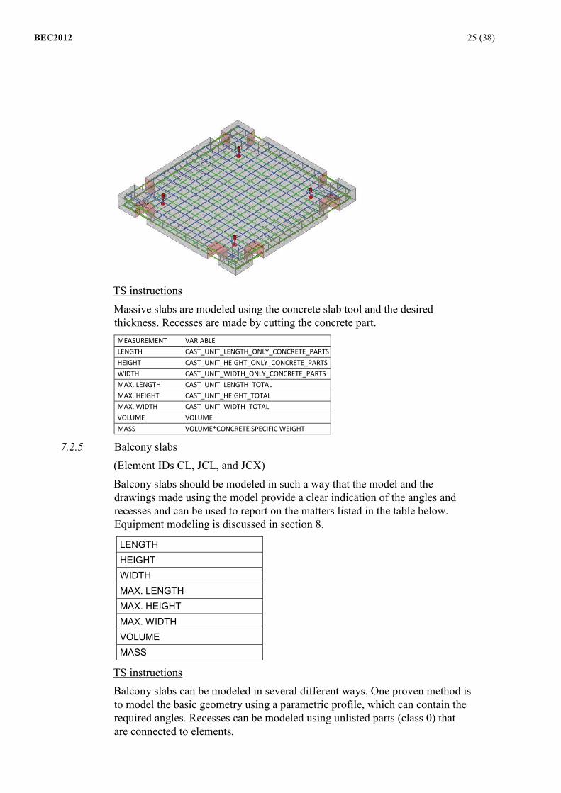
7.2.5 Balcony slabs (Element IDs CL, JCL, and JCX) Balcony slabs should be modeled in such a way that the model and the drawings made using the model provide a clear indication of the angles and recesses and can be used to report on the matters listed in the table below. Equipment modeling is discussed in section 8.
LENGTH HEIGHT WIDTH MAX. LENGTH MAX. HEIGHT MAX. WIDTH VOLUME MASS
TS instructions Balcony slabs can be modeled in several different ways. One proven method is to model the basic geometry using a parametric profile, which can contain the required angles. Recesses can be modeled using unlisted parts (class 0) that are connected to elements.

BEC2012 26 (38)
7.2.6 Sandwich-type elements (Element IDs AN, AS, AR, S, R, SKR, RKR, NK, and N)
Sandwich-type elements should be modeled in such a way that the model can be used to report on the matters listed in the table below. The thickness should be given as the thickness of the element's main part without protrusions or similar. Equipment modeling is discussed in section 8.
LENGTH HEIGHT THICKNESS MAX. LENGTH MAX. HEIGHT MAX. WIDTH THICKNESS (INNER SKIN) THICKNESS (INSULATION) THICKNESS (OUTER SKIN) VOLUME (INNER SKIN) VOLUME (OUTER SKIN) MASS GROSS AREA NET AREA + SURFACE TREATMENTS (AS AGREED)
The elementtisuunnittelu.fi website contains instructions that should be used for quantity surveying.
TS instructions
BEC2012 27 (38)
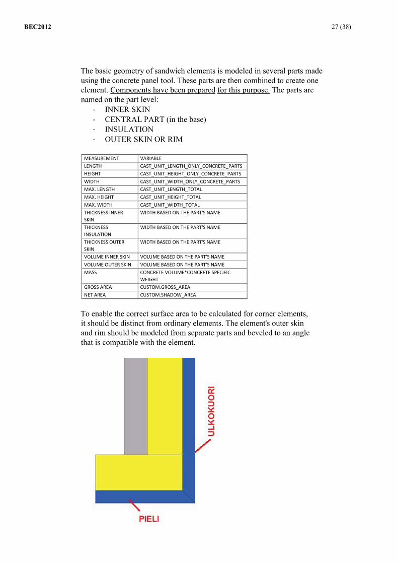
The basic geometry of sandwich elements is modeled in several parts made using the concrete panel tool. These parts are then combined to create one element. Components have been prepared for this purpose. The parts are named on the part level:
- INNER SKIN - CENTRAL PART (in the base) - INSULATION - OUTER SKIN OR RIM
MEASUREMENT VARIABLE LENGTH CAST_UNIT_LENGTH_ONLY_CONCRETE_PARTS HEIGHT CAST_UNIT_HEIGHT_ONLY_CONCRETE_PARTS WIDTH CAST_UNIT_WIDTH_ONLY_CONCRETE_PARTS MAX. LENGTH CAST_UNIT_LENGTH_TOTAL MAX. HEIGHT CAST_UNIT_HEIGHT_TOTAL MAX. WIDTH CAST_UNIT_WIDTH_TOTAL THICKNESS INNER SKIN
WIDTH BASED ON THE PART'S NAME
THICKNESS INSULATION
WIDTH BASED ON THE PART'S NAME
THICKNESS OUTER SKIN
WIDTH BASED ON THE PART'S NAME
VOLUME INNER SKIN VOLUME BASED ON THE PART'S NAME VOLUME OUTER SKIN VOLUME BASED ON THE PART'S NAME MASS CONCRETE VOLUME*CONCRETE SPECIFIC
WEIGHT GROSS AREA CUSTOM.GROSS_AREA NET AREA CUSTOM.SHADOW_AREA
To enable the correct surface area to be calculated for corner elements, it should be distinct from ordinary elements. The element's outer skin and rim should be modeled from separate parts and beveled to an angle that is compatible with the element.

BEC2012 28 (38)
Factory-plastered elements are modeled without the plaster's edge detailing. However, the detailing that is required to fabricate the elements must be added to the drawings.
7.2.7 Hollow-core slab types
(Element IDs O, 15O, 2O, YO, OK, KL, and EO) Hollow-core slabs should be modeled in such a way that the model can be used to report on the matters listed in the table below. Equipment modeling is discussed in section 8.
GROSS M2
WIDTH THICKNESS LENGTH LENGTH2 (short side) MASS
The elementtisuunnittelu.fi website contains instructions that should be used for quantity surveying.
TS instructions
Modeling is carried out from one part of the unit using the beam tool or the components designed for slabs.
MEASUREMENT VARIABLE GROSS M2 CAST_UNIT_LENGTH_ONLY_CONCRETE_PARTS *1.2 WIDTH CAST_UNIT_WIDTH_ONLY_CONCRETE_PARTS THICKNESS CAST_UNIT_HEIGHT_ONLY_CONCRETE_PARTS LENGTH CAST_UNIT_LENGTH_ONLY_CONCRETE_PARTS LENGTH (SHORT SIDE)
Requires further development
MASS WEIGHT
Some element suppliers are able to fabricate hollow-core slabs without measurement drawings. These suppliers can read the information directly from the model. For this reason, the openings and recesses to be made in hollow-core slabs should be correctly named. TS has components for making recessed slabs, and SUR and VUR cavities.

BEC2012 29 (38)
Photo: The opening components for hollow-core slabs in TS For manual modeling, the openings must be named in the cutting object's name field. Openings to be named:
- Recesses for electrics: SUR
- Sewage: VUR
- Fixing recess: SKK
- Support opening: TUK Insulated slabs are modeled in the same way as hollow-core slabs. The insulation is modeled in the same way as other equipment (see section 8). When reports are created on insulated slabs, the type and surface area of the insulation is reported in addition to the hollow-core slab information.

BEC2012 30 (38)
8 Modeling Casting Equipment and Producing Tables Casting equipment is added to concrete elements in such a way that it is possible to create a list of all of the equipment for the element with the correct information and the correct units (see the example below). The concrete precast fabrication industry can provide further information about materials along with the measurements and units that must be reported on. This subject should be addressed during the kickoff meeting.
EPS150 3,6 m2 OL-E-240 5,8 m2 SBKL 150x150 1,0 units AEP400 PA 5,0 units NEOPRENE TAPE 20x10 SHORE60 14,2 m NEOPRENE 200x300 SHORE60 2,0 units NEOPRENE 8 mm 0,5 m2 Spigot T16 L=1200 A500HW 2,0 UNITS STANDARD STEEL PIPE 100X60 S=2 mm 4,0 UNITS TW25 l=1800 M24-170 4,0 UNITS TIMBER 50X100 SAWN 7,6 m HELICAL SEAM PIPE D150 L=380 6,0 UNITS PIPE PENETRATION RESERVATION PLV 50X90
2,0 UNITS
ELECTRIC POINT RECESS 2,0 UNITS SEWATEK PENETRATION 1,0 UNITS HOISTING LINK JB20 2,0 units HOISTING LINK PB16 EXTRA BEND 2,0 units STEEL MESH 8-150 B500K 12,8 KG LEDGER MESH L18/10 B500K 6,0 UNITS HELICAL STIRRUP K7 750x750 60 rev B400 2,0 UNITS CLINKER SLAB 12,5 m2 KL 285x85/85 SAHARA SMOOTH 268,0 units SPECIAL STEEL PART SEE PICTURE 4,0 units
TS instructions Equipment can be added to elements in TS in several different ways depending on the equipment and the modeling method.
1) If the equipment has been modeled and a component has been created from it: Select the desired component using the select component option and the command Assembly -> Add as Sub-Assembly and then select the element.
Photo: The component select icon in TS
BEC2012 31 (38)
2) If the equipment has been modeled but no component has been created from it: Select the desired item of equipment using the select assembly option and the command Assembly -> Add as Sub-Assembly and then select the element.
Photo: The assembly select icon in TS
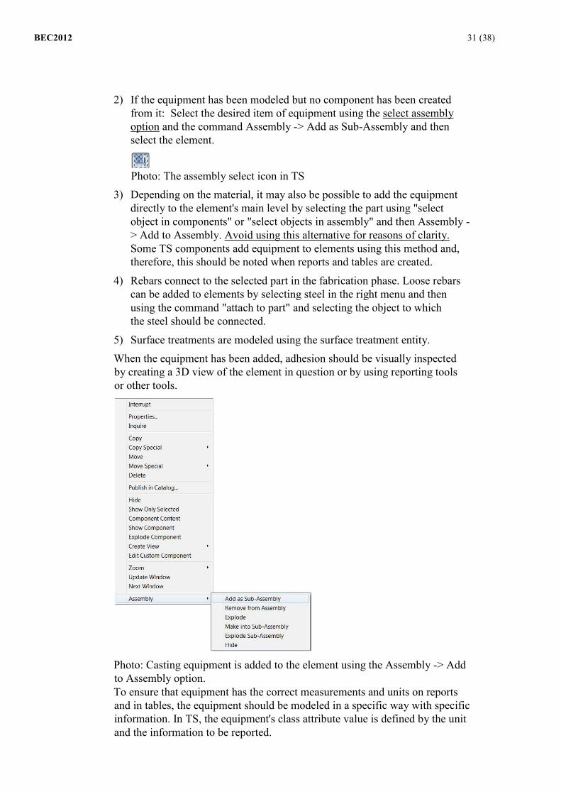
3) Depending on the material, it may also be possible to add the equipment directly to the element's main level by selecting the part using "select object in components" or "select objects in assembly" and then Assembly -> Add to Assembly. Avoid using this alternative for reasons of clarity. Some TS components add equipment to elements using this method and, therefore, this should be noted when reports and tables are created.
4) Rebars connect to the selected part in the fabrication phase. Loose rebars can be added to elements by selecting steel in the right menu and then using the command "attach to part" and selecting the object to which the steel should be connected.
5) Surface treatments are modeled using the surface treatment entity. When the equipment has been added, adhesion should be visually inspected by creating a 3D view of the element in question or by using reporting tools or other tools.
Photo: Casting equipment is added to the element using the Assembly -> Add to Assembly option. To ensure that equipment has the correct measurements and units on reports and in tables, the equipment should be modeled in a specific way with specific information. In TS, the equipment's class attribute value is defined by the unit and the information to be reported.
BEC2012 32 (38)
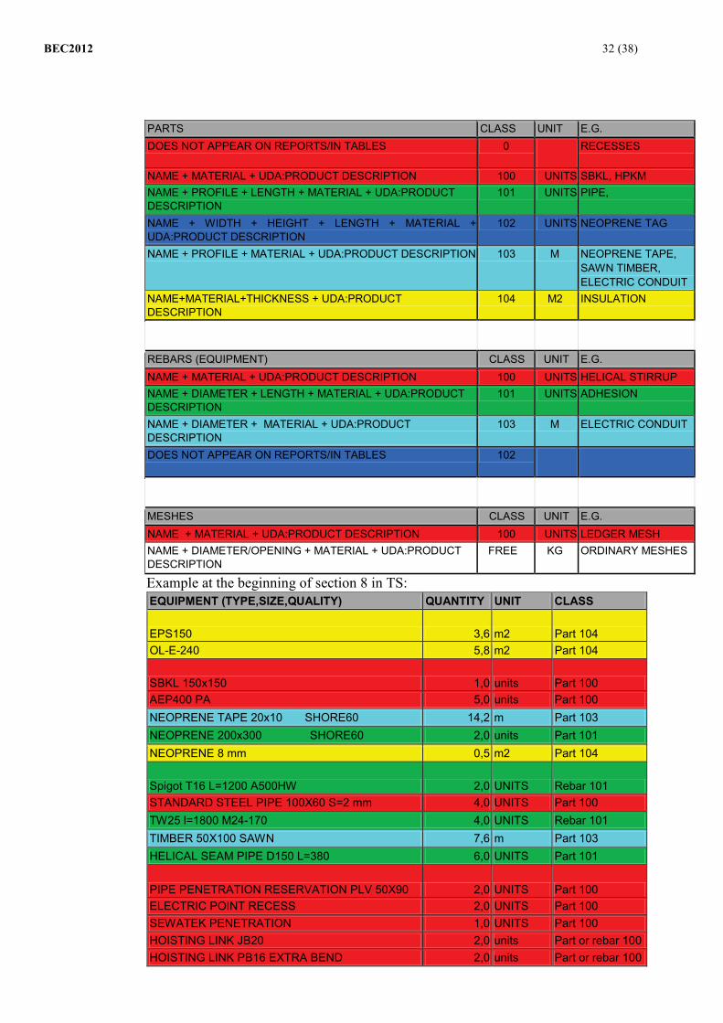
PARTS CLASS UNIT E.G. DOES NOT APPEAR ON REPORTS/IN TABLES 0 RECESSES
NAME + MATERIAL + UDA:PRODUCT DESCRIPTION 100 UNITS SBKL, HPKM NAME + PROFILE + LENGTH + MATERIAL + UDA:PRODUCT DESCRIPTION
101 UNITS PIPE,
NAME + WIDTH + HEIGHT + LENGTH + MATERIAL + UDA:PRODUCT DESCRIPTION
102 UNITS NEOPRENE TAG
NAME + PROFILE + MATERIAL + UDA:PRODUCT DESCRIPTION 103 M NEOPRENE TAPE, SAWN TIMBER, ELECTRIC CONDUIT
NAME+MATERIAL+THICKNESS + UDA:PRODUCT DESCRIPTION
104 M2 INSULATION
REBARS (EQUIPMENT) CLASS UNIT E.G. NAME + MATERIAL + UDA:PRODUCT DESCRIPTION 100 UNITS HELICAL STIRRUP NAME + DIAMETER + LENGTH + MATERIAL + UDA:PRODUCT DESCRIPTION
101 UNITS ADHESION
NAME + DIAMETER + MATERIAL + UDA:PRODUCT DESCRIPTION
103 M ELECTRIC CONDUIT
DOES NOT APPEAR ON REPORTS/IN TABLES 102
MESHES CLASS UNIT E.G. NAME + MATERIAL + UDA:PRODUCT DESCRIPTION 100 UNITS LEDGER MESH NAME + DIAMETER/OPENING + MATERIAL + UDA:PRODUCT DESCRIPTION
FREE KG ORDINARY MESHES
Example at the beginning of section 8 in TS: EQUIPMENT (TYPE,SIZE,QUALITY) QUANTITY UNIT CLASS
EPS150 3,6 m2 Part 104 OL-E-240 5,8 m2 Part 104
SBKL 150x150 1,0 units Part 100 AEP400 PA 5,0 units Part 100 NEOPRENE TAPE 20x10 SHORE60 14,2 m Part 103 NEOPRENE 200x300 SHORE60 2,0 units Part 101 NEOPRENE 8 mm 0,5 m2 Part 104
Spigot T16 L=1200 A500HW 2,0 UNITS Rebar 101 STANDARD STEEL PIPE 100X60 S=2 mm 4,0 UNITS Part 100 TW25 l=1800 M24-170 4,0 UNITS Rebar 101 TIMBER 50X100 SAWN 7,6 m Part 103 HELICAL SEAM PIPE D150 L=380 6,0 UNITS Part 101
PIPE PENETRATION RESERVATION PLV 50X90 2,0 UNITS Part 100 ELECTRIC POINT RECESS 2,0 UNITS Part 100 SEWATEK PENETRATION 1,0 UNITS Part 100 HOISTING LINK JB20 2,0 units Part or rebar 100 HOISTING LINK PB16 EXTRA BEND 2,0 units Part or rebar 100
BEC2012 33 (38)
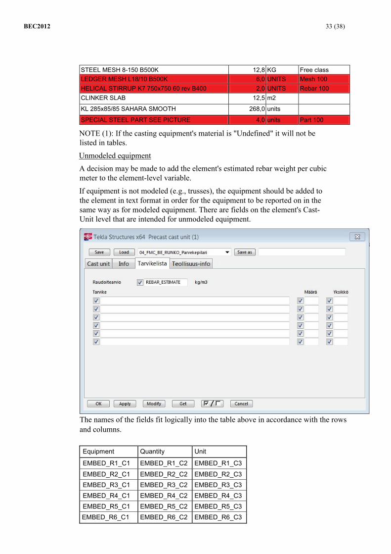
STEEL MESH 8-150 B500K 12,8 KG Free class LEDGER MESH L18/10 B500K 6,0 UNITS Mesh 100 HELICAL STIRRUP K7 750x750 60 rev B400 2,0 UNITS Rebar 100 CLINKER SLAB 12,5 m2 KL 285x85/85 SAHARA SMOOTH 268,0 units SPECIAL STEEL PART SEE PICTURE 4,0 units Part 100
NOTE (1): If the casting equipment's material is "Undefined" it will not be listed in tables. Unmodeled equipment A decision may be made to add the element's estimated rebar weight per cubic meter to the element-level variable.
If equipment is not modeled (e.g., trusses), the equipment should be added to the element in text format in order for the equipment to be reported on in the same way as for modeled equipment. There are fields on the element's Cast-Unit level that are intended for unmodeled equipment.
The names of the fields fit logically into the table above in accordance with the rows and columns. Equipment Quantity Unit EMBED_R1_C1 EMBED_R1_C2 EMBED_R1_C3 EMBED_R2_C1 EMBED_R2_C2 EMBED_R2_C3 EMBED_R3_C1 EMBED_R3_C2 EMBED_R3_C3 EMBED_R4_C1 EMBED_R4_C2 EMBED_R4_C3 EMBED_R5_C1 EMBED_R5_C2 EMBED_R5_C3 EMBED_R6_C1 EMBED_R6_C2 EMBED_R6_C3

BEC2012 34 (38)
Example 1: Pipe preferences, when a name, profile size, length, and material are desired for the pipe.
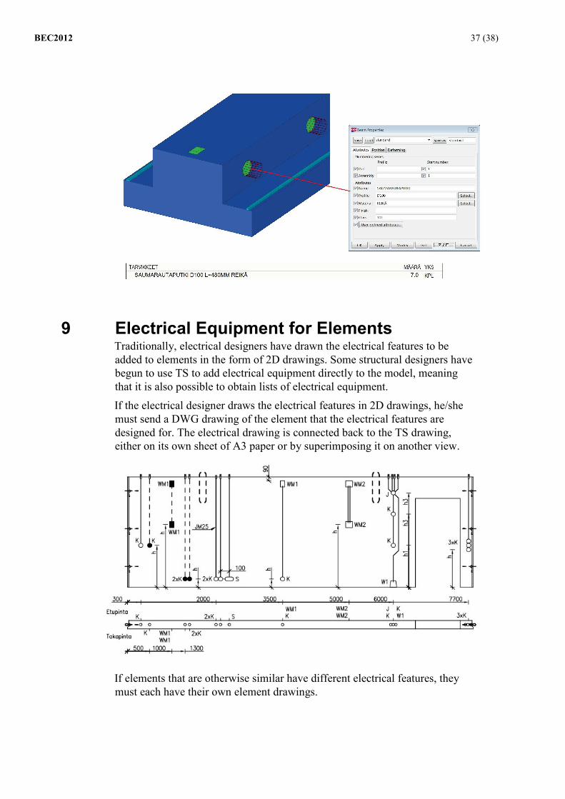
Example 2: Hoisting link as a steel assembly with an extra bend

BEC2012 35 (38)
Example 3: Threaded adhesion modeled with rebars

BEC2012 36 (38)
8.1.1 Openings and recesses: Precast fabrication industry also requires information about openings that will be made in the elements. The required information about openings and recesses is added to the casting equipment list. The openings that must be listed are as follows:
• Joint conduits • Boltholes • Large penetrations for HI and I beams • Further opening lists may be agreed on for the project
TS instructions Cutting objects are not listed in tables in TS, so the openings and recesses that must be listed should be modeled in such a way that the element is cut by a part that is connected to the element.
- The opening objects (part and cut) that must be listed are modeled using the materials OPENING or RECESS
- Opening information is listed on the casting equipment list following the same principles and using the same classes as casting equipment: the opening that penetrates the element must be modeled to the measurements of the penetrating part using the correct profile.
BEC2012 37 (38)
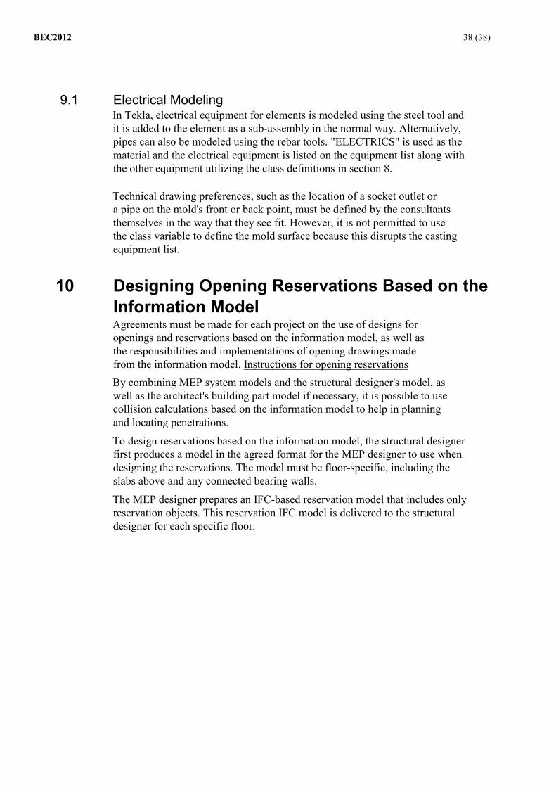
9 Electrical Equipment for Elements Traditionally, electrical designers have drawn the electrical features to be added to elements in the form of 2D drawings. Some structural designers have begun to use TS to add electrical equipment directly to the model, meaning that it is also possible to obtain lists of electrical equipment.
If the electrical designer draws the electrical features in 2D drawings, he/she must send a DWG drawing of the element that the electrical features are designed for. The electrical drawing is connected back to the TS drawing, either on its own sheet of A3 paper or by superimposing it on another view.
If elements that are otherwise similar have different electrical features, they must each have their own element drawings.
BEC2012 38 (38) 9.1 Electrical Modeling
In Tekla, electrical equipment for elements is modeled using the steel tool and it is added to the element as a sub-assembly in the normal way. Alternatively, pipes can also be modeled using the rebar tools. "ELECTRICS" is used as the material and the electrical equipment is listed on the equipment list along with the other equipment utilizing the class definitions in section 8. Technical drawing preferences, such as the location of a socket outlet or a pipe on the mold's front or back point, must be defined by the consultants themselves in the way that they see fit. However, it is not permitted to use the class variable to define the mold surface because this disrupts the casting equipment list.
10 Designing Opening Reservations Based on the Information Model Agreements must be made for each project on the use of designs for openings and reservations based on the information model, as well as the responsibilities and implementations of opening drawings made from the information model. Instructions for opening reservations By combining MEP system models and the structural designer's model, as well as the architect's building part model if necessary, it is possible to use collision calculations based on the information model to help in planning and locating penetrations.
To design reservations based on the information model, the structural designer first produces a model in the agreed format for the MEP designer to use when designing the reservations. The model must be floor-specific, including the slabs above and any connected bearing walls.
The MEP designer prepares an IFC-based reservation model that includes only reservation objects. This reservation IFC model is delivered to the structural designer for each specific floor.

BEC2012 39 (38)
Photo: The MEP designer's IFC reservation object in the structural designer's model. Every reservation object should contain information about whose reservation it represents. The size and IDs of reservations are added to the reservation object in the form of attribute data. Reservations must be modeled correctly with regard to their size and location.
The absolute height is used as the altitude value. Reservation objects should be modeled with greater thickness than penetrating structures to make visual inspection easier and to facilitate the structural designer's work in creating reservations.
The structural designer uses information about the opening reservation objects to make openings and other reservations in the structures, if this is structurally possible. If it is not structurally possible to make an opening, the structural designer informs the MEP designer, who prepares new versions of the opening reservation objects based on the structural designer's suggestions and then sends them to the structural designer. For technical reasons it is recommended that when opening reservation objects are changed, the modeled object be edited (e.g., size or location), instead of removing the object and replacing it with a new one. This enables the software to identify opening reservation objects as edited opening reservations rather than new objects. As regards electrical conduits, recesses for cases, and similar routes through the element, opening reservation designs based on the information model are not required when reservation drawings are created for elements. MEP applications do not support processing of element recesses. However, reservations that pierce the element entirely must be delivered in the form of opening reservation objects. The MEP designer presents the recesses and similar reservations to the structural designer in accordance with traditional design procedures.

BEC2012 40 (38) 10.1 Process for Preparing Opening Drawings
When openings and reservations are designed based on the information model, the preparation, responsibilities, and procedures must be agreed on by the building designer and the MEP designer for each project. A draftsman must be selected to prepare the 2D opening drawing when the design agreements are made. For each project, it is important to ensure that the software applications used by the building designer and the MEP designer are compatible. Instructions for 2D opening drawings Opening designs and reservation designs based on the information model can be utilized in several ways to create 2D opening drawings. These procedures or variations of these procedures can be considered for use when the site requires 2D opening drawings. All of these procedures operate in accordance with section 8.3.
Alternative 1
• The structural designer delivers 2D and 3D opening drawing templates to the MEP designer.
• The MEP designer utilizes his/her own opening reservation objects and makes 2D opening drawings based on them, including dimension lines.
• The opening reservations are primarily dimensioned to the module network or, alternatively, to existing structures in the case of renovation
• The 2D opening reservation files are delivered to the building designer.
• The structural designer makes hardcopies and distributes the opening pictures.
Alternative 2
• The structural designer delivers 3D opening drawing templates to the MEP designer for each floor at absolute height.
• The MEP designer makes opening reservation objects at the model's altitude and delivers them to the structural designer in IFC form.
• The structural designer prepares 2D opening drawings, including dimension lines and measurements, based on the MEP designer's opening reservation objects. The drawings are then distributed to all relevant parties.
Alternative 3: • The structural designer delivers 3D opening drawing templates
to the MEP designer for each floor at absolute height. • The MEP designer makes opening reservation objects at the
model's altitude and delivers them to the structural designer in IFC form.
• The structural designer makes 2D opening picture templates that show the MEP designer's opening reservations

BEC2012 41 (38)
• The structural designer adds a dimension line to the picture based on the opening reservation information (e.g., "IU, 300x200, KP=+25.3"). This information is taken from the MEP designer's opening reservation objects.
• The structural designer adds a measurement design level to this 2D picture for the various design disciplines, using the color that they require dimension lines to be printed in (= the line thickness in monochrome printouts).
• The structural designer delivers the 2D opening picture templates and other material to the MEP designer
• The MEP designer makes dimension lines at the level made by the structural engineer using the CAD application's normal dimension line tools
• The opening reservations are primarily dimensioned to the module network or, alternatively, to existing structures in the case of renovation
• The 2D opening reservation files, complete with dimension lines, are delivered to the structural designer
• The structural designer makes hardcopies and distributes the opening pictures to all relevant parties.
11 Annotations for Design Status and Date In long-term projects, elements may have different design statuses. The project may be partially built and in use as other parts are still being designed. It must be possible to establish the model's publication date and the elements' design status at various stages, with the required date labels. Section 4.3 describes the division of structural modeling duties among different organizations. In accordance with the example in the aforementioned section, the same element may appear in the head structural designer's model and in the element designer's model. Information about the design status can also be used to manage these operations. The elements remain at the design status set out in the head structural designer's model, enabling them to be used for purposes such as scheduling, even though the elements are modeled in detail in a totally different model.
11.1 Designs It must be possible to establish the design's planned date of completion, the elements' design status, and the date of the design status.
Designed by: Design status: Design status date: Design comment:

BEC2012 42 (38)
TS instructions Information about the design status and date is defined in the assembly-level variable.
Designed by: PLANNED_END_D Design status: DESIGN_STATUS Design status date: DESIGN_STATUS_DATE Design comment: DESIGN_COMMENT
Design statuses must be documented in the information model specification to ensure that the parties involved in the project are able to interpret them correctly. The design status should be edited whenever drawings are printed for publication. The design status is defined on an 11-step scale:
- Designers can use values 01–09 freely to define the statuses of incomplete elements. Design bureaus can edit the design status definitions providing that the numerical part remains before the information about the design status.
- Value 10_Ready describes a element and drawing that is complete - Value 11_Changed describes an element and drawing that have
changed
Photo: The design status and date fields
11.2 Fabrication Fabricators add their own details on the design status, date, and any other relevant information to the model.
Fabricator's internal design status: Strand information: Fabrication status: Fabrication date: Fabrication ID: Plant: Fabrication comment:

BEC2012 43 (38)
TS instructions Information about fabrication is defined in the assembly-level variable.
Fabricator's internal design status: FAB_DESIGN_STATUS Strand information: FAB_STRAND_INFO Fabrication status: FABRICATION_STATUS Fabrication date: FAB_STATUS_DATE Fabrication ID: FAB_ID Plant: FAB_PLANT Fabrication comment: FAB_COMMENT
Photo: Fabrication information fields
11.3 Delivery The supplier of the completed parts enters information related to deliveries into the model.
Delivery date: Delivery number Delivery document Delivery comment
TS instructions Information about delivery is defined in the assembly-level variable.
Delivery date: DELIVERY_DATE Delivery number DELIVERY_NUMBER Delivery document SHIPMENT_NUMBER Delivery comment DELIVERY_COMMENT

BEC2012 44 (38)
Photo: Delivery information fields
11.4 Erection Information about the installation is added to the model by the erector of the completed parts.
Planned installation: Erection order Erection completed: Erection comment TS instructions Information about delivery is defined in the assembly-level variable.
Planned installation: PLANNED_END_E Erection order EREC_NUMBER Erection completed: ACTUAL_END_E Erection comment ERECTION_COMMENT
Photo: Erection information fields
11.5 Model publication date It must be possible to establish the model's publication date.
TS instructions The model's publication date is entered into TS under the Project properties - user-defined-attribute information in the MODEL_DATE field.

BEC2012 45 (38)
Photo: Model publication date field
12 Drawings Model drawings based on the information model have been prepared for the BEC 2012 project. The model drawings have been inspected and approved by the precast fabrication industry, so they can be used as an example when drawings are being created for the project.
The following matters are important: - The overall look and legibility of the drawings - Views and contents - Measurement principles - Table structure and content - Content of the rebar and equipment IDs - Viewing angles
Model drawings and related TS models can be found on the elementtisuunnittelu.fi website.