modeling gps phase multipath with snr: case study...
TRANSCRIPT
Modeling GPS phase multipath with SNR:
Case study from the Salar de Uyuni, Boliva
Andria Bilich,1 Kristine M. Larson,2 and Penina Axelrad2
Received 30 May 2007; revised 30 October 2007; accepted 18 December 2007; published 1 April 2008.
[1] Multipath, wherein a signal arrives at the receiving antenna by more than one path, isa significant and largely unmodeled source of GPS positioning error. We present atechnique for mitigating specular multipath in GPS carrier phase measurements using thesignal-to-noise ratio (SNR), in which the frequency and amplitude content ofnon-stationary oscillations in SNR are modeled to extract multipath parameters (direct andreflected signal amplitudes, and the phase difference between direct and indirect signals).The frequency content of SNR data is estimated using wavelet analysis, then used toinitialize an adaptive least squares process to solve for time-varying multipath parameters.Multipath corrections derived from these parameters are applied to the phase observables.We demonstrate this technique using campaign GPS data collected over a large salt flat(Salar de Uyuni), specifically a tripod-mounted station which experienced long-period(300–2000 s) multipath oscillations in SNR from ground reflections. By contrastingposition solutions before and after applying multipath corrections, we demonstrate areduction in carrier phase postfit residual RMS of up to 20% for static positioning, and1–7 dB reduction in spectral power at multipath periods for kinematic positions.
Citation: Bilich, A., K. M. Larson, and P. Axelrad (2008), Modeling GPS phase multipath with SNR: Case study from the
Salar de Uyuni, Boliva, J. Geophys. Res., 113, B04401, doi:10.1029/2007JB005194.
1. Introduction
[2] A precise model for the carrier phase observable iscrucial to high-precision Global Positioning System (GPS)applications such as geodesy. Although many GPS modelimprovements have been made in the last decade [e.g.,Springer et al., 1998; Mader, 1999; Altamimi et al., 2002;Kedar et al., 2003], to date there is no accepted model toaccount for multipath effects, specifically the effects ofspecular multipath (reflections from a smooth surfaceresulting in slowly varying systematic errors) on the GPScarrier phase. Specular multipath leads to positioning errorswhether position is computed at every epoch [Larson et al.,2007; Choi et al., 2004; Bock et al., 2000] or a singleposition is determined from 24 h of data [Elosegui et al.,1995]. In high multipath environments these range errorscan be substantial, on the order of meters for pseudorangeand several centimeters for phase [Braasch, 1996].[3] Our method for modeling and correcting carrier phase
multipath relies on signal-to-noise ratio (SNR) data. Earlierstudies incorporated SNR measurements in correcting car-rier phase multipath in aerospace environments [Comp andAxelrad, 1997; Reichert, 1999; Reichert and Axelrad, 1999]with a master and several slave antennas in a closely spacedarray, i.e., differential multipath. Comp and Axelrad [1997]
demonstrated how differential carrier phase multipath couldbe reduced up to 47% by modeling the frequency andamplitude content of differential SNR. Ray [2000] andRay and Cannon [2001] developed a method for jointlyfiltering single-differenced measurements of code, carrierphase, and SNR to determine multipath parameters. Subse-quent multipath corrections resulted in an average of 22%and 15% reduction in code and carrier residuals, respec-tively. Accuracy was improved by 21% and 24% fordifferential code and carrier positioning, respectively.[4] This study adapts the differential-multipath method-
ology to undifferenced carrier phase data so that the methodcan be applied to the stand-alone GPS stations commonlyused in geodetic networks. For this type of application, aneffective phase multipath mitigation technique would takeinto account a number of features unique to geodetic andCGPS sites, networks, and archives: solitary GPS antennaslocated in both rural and urban environments; the variety ofexisting GPS receiver models; antenna orientations withlittle below-horizon (<0�) observability of GPS satellites;and large existing archives of GPS data with variablesample intervals. Thus this study establishes a techniqueto correct single-station phase multipath using undiffer-enced observables. This technique is not receiver-specificnor designed specifically for real-time operation. It couldpotentially be applied to various models and types of GPSreceivers using observables already available in archiveddata.[5] The paper first outlines the relationships between
SNR and phase multipath, and demonstrates how multipatherrors in carrier phase observables are a function of the
JOURNAL OF GEOPHYSICAL RESEARCH, VOL. 113, B04401, doi:10.1029/2007JB005194, 2008ClickHere
for
FullArticle
1National Geodetic Survey, Boulder, Colorado, USA.2Department of Aerospace Engineering Sciences, University of
Colorado, Boulder, Colorado, USA.
Copyright 2008 by the American Geophysical Union.0148-0227/08/2007JB005194$09.00
B04401 1 of 12

frequency and amplitude content of SNR data. SNR data areused to generate profiles of carrier phase multipath forindividual satellites, and the profiles are subsequently usedto remove carrier phase multipath errors. Least squaresposition solutions with and without the correction profilesare then computed and evaluated. The advantages andlimitations of this technique in the context of a simplifiedmultipath environment are also discussed.
2. SNR and Carrier Phase Multipath Theory
[6] This section uses terminology specific to GPS mul-tipath, which is summarized here and in Table 1. In amultipath-free environment, the receiver intercepts signalstraveling a direct path between the GPS satellites and areceiver, so that the single-channel signal power is equiv-alent to the direct signal amplitude, denoted Ad for anindividual satellite. Upon reflection from a surface, anindirect signal is attenuated so that its amplitude Am is lessthan the direct, i.e., Am � Ad. In some cases it is useful todescribe the multipath and direct amplitudes as a ratio, a =Am/Ad. Because reflected signals arrive by an indirect path,the reflected signal has a longer path length than thedirect. This additional path length, referred to as the pathdelay (d), creates a range error, which subsequently leadsto a positioning error. The phase multipath error isexpressed as df, in units of cycles. The reflected signal’scarrier wave, upon reception by the GPS antenna, will likelyhave a different phase than the direct signal; the difference inthe phases of the two signals is described as the multipathrelative phase, y .[7] Although derivations of the exact multipath-SNR rela-
tionships have been given by many others [Axelrad et al.,2005; Ray, 2000; Comp, 1996; Georgiadou and Kleusberg,1988], the salient equations are summarized here to demon-strate that, in theory, the frequency and amplitude content ofSNR data are directly related to carrier phase multipatherrors. We direct the reader to Bilich and Larson [2007] forprecise derivations and additional background material. Un-der the simplified model of GPS signal tracking in thepresence of direct and reflected signals, multipath-SNRequations can be derived which express the phase error df
and the signal-to-noise ratio S in terms of the multipathparameters (Table 1):
tanðdfÞ ¼ Am sinyAd þ Am cosy
ð1Þ
S2 ¼ A2d þ A2
m þ 2AdAm cosy ð2Þ
Because the time-dependent behavior of both thesequantities is dominated by the sine or cosine of y , it isimportant to understand the time-dependency of the multi-path relative phase. As discussed by Comp [1996] andBilich and Larson [2007], y is a function of the receiver-satellite geometry (Figure 1): the perpendicular antenna-reflector distance h and several angles measured relative tolocal horizontal, i.e., the angle of reflection at the surface b,the satellite elevation angle q, and reflector tilt g:
y ¼ 2pl2h sin b ð3Þ
y ¼ 2pl2h sinðjq� gjÞ ð4Þ
where l is the GPS wavelength. Note that the absolutevalue in equation (4) is a general formulation of b which
Table 1. Summary of Symbols Used for Multipath Terms
Symbol Term Units
AmplitudesAm multipath signal amplitude voltsAd direct signal amplitude voltsa amplitude ratio of multipath
to direct; a = Am/Ad
unitless
Anglesy multipath relative phase; phase difference
between indirect and direct signalsradians
q satellite elevation angle, relative to local horizontal radiansb angle of reflection radiansg angle of reflector tilt, relative to local horizontal radians
Errorsd path delay; additional path length traveled by
indirect signal relative to the directmeters
rMP pseudorange error due to multipath metersdf carrier phase error due to multipath cycles
Figure 1. Geometry of a forward-scatter specular multi-path reflection from a planar surface tilted at angle g andlocated at a distance h from the antenna phase center. Theangle of incidence b at the surface is equivalent to the angleof reflection, and q is the satellite elevation angle. Boldarrows show the additional path length (d = 2hsinb) traveledby the multipath signal relative to the direct. All objects areconsidered coplanar (no third dimension), and all angles aredefined relative to local horizotal.
B04401 BILICH ET AL.: GPS PHASE MULTIPATH WITH SNR
2 of 12
B04401
holds true for both forward (Figure 1) and backscattergeometries [Bilich, 2006]. By assuming reflecting objectspersist so that g and h are constant, the only time-dependentfactor remaining in equation (4) is the satellite motion(satellite elevation angle). Taking the time-derivative of y :
dydt
¼ 2pl2h cosðq� gÞj dq
dtj ð5Þ
As will be shown below, the sign of dy /dt must beunambiguous for proper computation of multipath phasecorrections. If we assume that g is both time-invariantand so small as to be negligible compared to q, b ffi qand db/dt ffi dq/dt. Thus the time-derivative of equation (3)becomes:
w dydt
¼ 2pl2h cos q
dqdt
ð6Þ
By assuming multipath reflections originate from flat groundor low-angle surfaces, resulting in a purely forward-scattergeometry, the sign of w dy /dt is determined simply byrecognizing if the satellite is ascending or descending as afunction of time. Therefore this study seeks to model onlyground multipath reflections with small g because the sign ofdy /dt for flat ground reflections is well-understood.
3. Multipath Estimation Methodology
[8] In order to correct for multipath on the GPS carrierphase, amplitudes Am and Ad and multipath relative phase ymust be estimated as a function of time. The previoussection provided the theoretical underpinnings of the rela-tionship between SNR and phase multipath; this sectionoutlines a method where SNR data are modeled to estimatethese multipath parameters as time-varying quantities. Theproposed method draws strongly from the algorithms usedby Comp [1996] and Comp and Axelrad [1997].[9] The following steps progress from SNR as reported
by the GPS receiver (S) to carrier phase multipath correc-tions (df). First, the SNR profile is separated into two parts:the SNR due to the direct signal, and the SNR due tomultipath. The SNR from the direct signal provides anestimate of the direct amplitude, and the residual SNRdue to multipath is employed in subsequent analysis stages.Next, the dominant multipath frequency as a function oftime is determined via wavelet analysis. The sign of eachmultipath frequency is determined by limiting the analysisto multipath reflections off of flat ground or moderatelytilted surfaces. Each time-localized estimate of multipathfrequency is then used in an adaptive least squares processto estimate the multipath relative phase and multipathamplitude. Once the multipath parameters Ad, Am, and yhave been determined, equations (1)–(2) are applied toconstruct carrier phase corrections for multipath errors whilealso reconstructing the SNR profile as a check on theestimation process. Although based upon the earlier workof Comp [1996] and Comp and Axelrad [1997] the processdescribed here has a few key changes and simplifications:estimation of multipath frequencies via wavelet analysis,modeling only single-antenna and single-reflector multipath,and incorporating assumptions of satellite-receiver geometry.
[10] The method described in this study is only applicableto receiver models that report SNR data in a way consistentwith the simplified multipath model described above. Wenote that it is likely that many high-quality receiversimplement some sort of proprietary multipath mitigationstrategies at the tracking level which would alter or negatethe simplified multipath model proposed here. However, itis difficult to confirm which GPS receiver models obey theabove SNR-multipath relationships without knowledge ofhow the SNR quantity is computed within the receiverhardware and firmware, and receiver manufacturers areoften reluctant to provide this information. This study usesSNR quantities recorded by the receiver and reported inRINEX files. When available in RINEX, SNR are reportedas observable types S1 and S2 and record ‘‘raw signalstrengths or SNR values as given by the receiver for L1, L2phase observations’’ [Gurtner, 1994]. SNR data qualityanalysis by Bilich et al. [2007] indicates that the AshtechZ-12 receivers report SNR for the L1 phase that areconsistent with the simplified multipath model, thereforeL1 Ashtech Z-12 data are used in this study.
3.1. Signal Component Separation
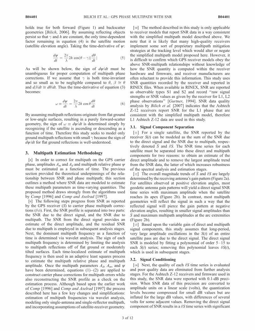
[11] For a single satellite, the SNR reported by thereceiver S(t) can be modeled as the sum of the SNR dueto the direct signal and the SNR due to multipath, respec-tively denoted �S and dS. The SNR time series for eachsatellite must be separated into these direct and multipathcomponents for two reasons: to obtain an estimate of thedirect amplitude and to remove the largest amplitude trendfrom the SNR data, the latter of which increases robustnessof the spectral analysis and estimation stages.[12] The overall magnitude trends of �S and dS are largely
determined by the receiving antenna’s gain pattern (Figure 2a).For satellites observed at positive elevation angles, mostgeodetic antenna gain patterns will yield a direct signal SNRtime series with maximum amplitude when the satellitereaches its apex (Figure 2b). In contrast, most multipathgeometries will reflect the signal in such a way that thereflected signal will pierce the gain pattern at negativeelevation angles, resulting in smaller signal amplitudes than�S and maximum multipath amplitudes at the arc extremities(Figure 2b).[13] Based upon the variable gain of direct and multipath
signal components, this study assumes that long-period,very large amplitude oscillations in the S(t) of an entiresatellite pass are due to the direct signal. The direct signalSNR is modeled by fitting a polynomial of order 5–15 toeach S(t) series; removing this polynomial leaves dS(t),which is used in subsequent stages.
3.2. Signal Conditioning
[14] Next, the quality of each dS time series is evaluatedand poor quality data are eliminated from further analysisstages. For the Ashtech Z-12 receivers and firmware used inthis study, the SNR data were reported with 0.1-dB preci-sion. When SNR data of this precision are converted toamplitude units on a linear scale (volts), the quantizationlevels become compressed for small dB values but areinflated for the large dB values, with differences of severalvolts for some adjacent values. Removing the direct signalcomponent of SNR results in a dS time series with significant
B04401 BILICH ET AL.: GPS PHASE MULTIPATH WITH SNR
3 of 12
B04401
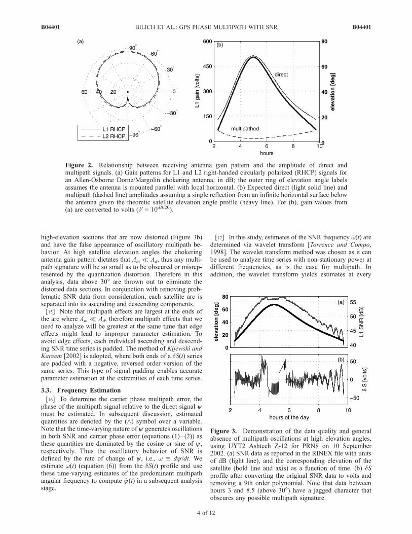
high-elevation sections that are now distorted (Figure 3b)and have the false appearance of oscillatory multipath be-havior. At high satellite elevation angles the chokeringantenna gain pattern dictates that Am Ad, thus any multi-path signature will be so small as to be obscured or misrep-resented by the quantization distortion. Therefore in thisanalysis, data above 30� are thrown out to eliminate thedistorted data sections. In conjunction with removing prob-lematic SNR data from consideration, each satellite arc isseparated into its ascending and descending components.[15] Note that multipath effects are largest at the ends of
the arc where Am Ad, therefore multipath effects that weneed to analyze will be greatest at the same time that edgeeffects might lead to improper parameter estimation. Toavoid edge effects, each individual ascending and descend-ing SNR time series is padded. The method of Kijewski andKareem [2002] is adopted, where both ends of a dS(t) seriesare padded with a negative, reversed order version of thesame series. This type of signal padding enables accurateparameter estimation at the extremities of each time series.
3.3. Frequency Estimation
[16] To determine the carrier phase multipath error, thephase of the multipath signal relative to the direct signal ymust be estimated. In subsequent discussion, estimatedquantities are denoted by the (^) symbol over a variable.Note that the time-varying nature of y generates oscillationsin both SNR and carrier phase error (equations (1)–(2)) asthese quantities are dominated by the cosine or sine of y ,respectively. Thus the oscillatory behavior of SNR isdefined by the rate of change of y , i.e., w dy /dt. Weestimate w(t) (equation (6)) from the dS(t) profile and usethese time-varying estimates of the predominant multipathangular frequency to compute y(t) in a subsequent analysisstage.
[17] In this study, estimates of the SNR frequency w(t) aredetermined via wavelet transform [Torrence and Compo,1998]. The wavelet transform method was chosen as it canbe used to analyze time series with non-stationary power atdifferent frequencies, as is the case for multipath. Inaddition, the wavelet transform yields estimates at every
Figure 2. Relationship between receiving antenna gain pattern and the amplitude of direct andmultipath signals. (a) Gain patterns for L1 and L2 right-handed circularly polarized (RHCP) signals foran Allen-Osborne Dorne/Margolin chokering antenna, in dB; the outer ring of elevation angle labelsassumes the antenna is mounted parallel with local horizontal. (b) Expected direct (light solid line) andmultipath (dashed line) amplitudes assuming a single reflection from an infinite horizontal surface belowthe antenna given the theoretic satellite elevation angle profile (heavy line). For (b), gain values from(a) are converted to volts (V = 10dB/20).
Figure 3. Demonstration of the data quality and generalabsence of multipath oscillations at high elevation angles,using UYT2 Ashtech Z-12 for PRN8 on 10 September2002. (a) SNR data as reported in the RINEX file with unitsof dB (light line), and the corresponding elevation of thesatellite (bold line and axis) as a function of time. (b) dSprofile after converting the original SNR data to volts andremoving a 9th order polynomial. Note that data betweenhours 3 and 8.5 (above 30�) have a jagged character thatobscures any possible multipath signature.
B04401 BILICH ET AL.: GPS PHASE MULTIPATH WITH SNR
4 of 12
B04401

epoch, which is necessary for error profile computation. Tocompute the continuous wavelet transform Wn, each paddeddS time series of length N samples and sampling interval dtis convolved with the wavelet function Y:
WnðsÞ ¼XN�1
n0 ¼ 0
dSn0Y*ðn0� nÞdt
s
� �ð7Þ
where the asterisk (*) is the complex conjugate operator. Inthe wavelet transform, a wavelet of scale s is essentiallytranslated along the time index n to ascertain the time-varying frequency and power of features in the time series.The continuous wavelet transform is approximated usingthe Fourier transform as outlined by Torrence and Compo[1998]. This study uses the Morlet wavelet, a sinusoidmodulated by a Gaussian, as the wavelet function Y. TheMorlet wavelet has both real and imaginary parts, thereforewe represent the amplitude of the wavelet transform usingthe wavelet power spectrum jWn(s)j2, a real-valued quantity.[18] The choice of wavelet scales determines the resolv-
able frequencies. In this study, the wavelet transform iscomputed over scales
sj ¼ s02jdj; j ¼ 0; 1; . . . ; J ð8Þ
J ¼ dj�1 log2 ðNdt=s0Þ ð9Þ
where s0 = 2dt is the smallest scale and J is the largest. Aspacing between scales of dj = 0.15 was chosen as this valueyielded sufficiently fine frequency resolution for slowlyvarying multipath. Equation (8) leads to discrete waveletscales which are further apart as the wavelength increases,that is for the longest periods or lowest frequencies. Atevery epoch, the scale with maximum wavelet power isassumed to be the dominant multipath contributor, and thatscale s is subsequently converted to an equivalent Fourierperiod or frequency. For any wavelet, the wavelet scale canbe directly related to the Fourier frequency w [Meyers et al.,1993]; for the Morlet wavelet w = 0.97s.[19] Before proceeding to amplitude and phase estima-
tion, the sign of the frequency values must be adjusted. TheSNR, the oscillatory time dependence of which is driven bycos(y), is insensitive to the sign of the change in multipathphase, thus wavelet analysis yields frequency values thathave no connection to the sign of w. However, the siny termin the denominator of equation (1) means that incorrectdetermination of the sign of w and therefore dy /dt will yieldan inverted phase correction profile, essentially doubling thepotential multipath error instead of removing it. Assuminghorizontal reflecting surfaces and forward scattering(equation (6)) allows us to avoid this pitfall by establish-ing that changes in y and q with time will haveequivalent sign. Thus the sign of w is adjusted to beconsistent with that of dq/dt, i.e., the ascending (+w) ordescending (�w) portion of a satellite arc, before estimat-ing the multipath parameters.
3.4. Multipath Parameter Estimation
[20] Adaptive least squares, hereafter referred to as ALS,allows dynamic determination of amplitude and phase as a
function of time. In this implementation, the ALS isinitialized with the frequency estimates w from the abovewavelet analysis and operates on the SNR data after thedirect signal has been removed. In theory, it is possible toestimate the multipath frequency w in addition to Ad, Am,and y using only dS as an input, but the ALS method isinsufficiently robust to estimate w in the presence of noise[Comp, 1996]; initializing the ALS with w increases ALSrobustness and aids convergence of the multipath parameterestimates.[21] The ALS estimates the multipath parameters by
modeling dS as a cosine C in the presence of noise e witha time-varying mean offset of A0 that accounts for theimperfect nature of the polynomial removal:
dSðtÞ ¼ A0ðtÞ þ C þ e
dSðtÞ ¼ A0ðtÞ þ AmðtÞ cosyðtÞ þ e ð10Þ
Equation (10) is given as a function of time t, where Am isthe multipath amplitude and y is the multipath relativephase. Although ALS can estimate multiple multipathcontributions at once, this study solves for a singledominant reflector.[22] The ALS operates on this linear model of periodic
signals embedded in noise (equation (10)). The multipathrelative phase is a function of the time-varying multi-path frequency (provided by wavelet analysis, here inradians), assumed to be constant from one epoch to thenext:
yðtkÞ ¼ wðtk�1Þdt þ yðtk�1Þ ð11Þ
The state vector at any epoch u(tk) is composed of sine (in-phase) and cosine (quadrature) components for eachperiodic signal, plus an additional element to estimate anymean offset A0:
�ðtkÞ ¼1
�s�c
0@
1A ¼
A0
AmðtkÞ sin yðtkÞAmðtkÞ cos yðtkÞ
0@
1A ð12Þ
The orthogonal sine and cosine components are included inthe state pair so that Am and y can be separately determined.From one time to the next, the state estimate is propagatedby the transition matrix,
Fðtk ; tk�1Þ ¼1 0 0
0 cosðwðtk�1ÞdtÞ sinðwðtk�1ÞdtÞ0 � sinðwðtk�1ÞdtÞ cosðwðtk�1ÞdtÞ
24
35 ð13Þ
Starting at high satellite elevation angles (low multipath)and moving toward the lower elevations (high multipath),the state is sequentially updated via least squares under theminimum variance criteria. In this adaptive implementationof least squares a forgetting factor is applied to discount oldmeasurements when updating the state and error covariance;forgetting factors of 0.99 for A0 and 0.95 for y are used in
B04401 BILICH ET AL.: GPS PHASE MULTIPATH WITH SNR
5 of 12
B04401
this study. A more detailed explanation of ALS is given byBilich [2006] and Comp [1996].[23] The desired estimates of multipath amplitude and
relative phase come from the magnitude and phase of theupdated orthogonal state pair:
AmðtÞ ¼ k �ðtÞ k¼ffiffiffiffiffiffiffiffiffiffiffiffiffiffiffiffiffiffiffiffiffiffiffiffiffiffiffi�2s ðtÞ þ �2cðtÞ
qð14Þ
yðtÞ ¼ arctan�sðtÞ�cðtÞ
� �ð15Þ
3.5. Multipath Profile Construction
[24] The combined wavelet and ALS method providesestimates of residual direct amplitude A0(t), multipath am-plitude Am(t), and multipath relative phase y(t) all as afunction of time. The residual direct amplitude is added tothe direct amplitude estimate from the signal separationstage to create the final estimate of Ad(t):
AdðtÞ ¼ �SðtÞ þ A0ðtÞ ð16Þ
These three multipath parameter estimates are all that isnecessary to construct phase multipath corrections. Sub-stituting these estimates into equation (1):
dfðtÞ ¼ arctanAmðtÞ sin yðtÞ
AdðtÞ þ AmðtÞ cos yðtÞ
!ð17Þ
This estimate of the phase error due to multipath df(t), inradians, can be used to correct GPS phase data corrupted bymultipath errors. Multiplication by l/2p converts the phaseerror into distance units so that the magnitude of the phaseerror can be understood in terms of a range error.[25] An estimated SNR profile S(t) serves as a check on
the multipath parameter estimates; if significant differencesexist between the raw SNR data and the reconstructed orestimated SNR profile, the estimates of one or moremultipath parameters is in error. From equation (2), thecomposite SNR, which includes both direct and multipatheffects, is:
SðtÞ ¼ffiffiffiffiffiffiffiffiffiffiffiffiffiffiffiffiffiffiffiffiffiffiffiffiffiffiffiffiffiffiffiffiffiffiffiffiffiffiffiffiffiffiffiffiffiffiffiffiffiffiffiffiffiffiffiffiffiffiffiffiffiffiffiffiffiffiffiffiffiffiffiffiffiffiA2
dðtÞ þ A2
mðtÞ þ AdðtÞAmðtÞ cos yðtÞq
ð18Þ
Because the SNR due only to multipath contains the mostvariation and has no dependency on direct multipathamplitude, constructing an estimate of the SNR due tomultipath can be a useful check on y and Am:
dSðtÞ ¼ AmðtÞ cos yðtÞ ð19Þ
4. Salar de Uyuni Experiment
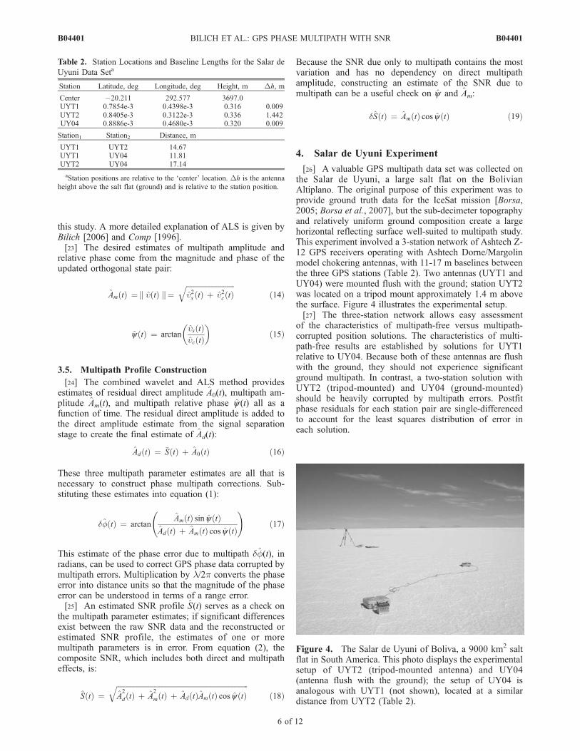
[26] A valuable GPS multipath data set was collected onthe Salar de Uyuni, a large salt flat on the BolivianAltiplano. The original purpose of this experiment was toprovide ground truth data for the IceSat mission [Borsa,2005; Borsa et al., 2007], but the sub-decimeter topographyand relatively uniform ground composition create a largehorizontal reflecting surface well-suited to multipath study.This experiment involved a 3-station network of Ashtech Z-12 GPS receivers operating with Ashtech Dorne/Margolinmodel chokering antennas, with 11-17 m baselines betweenthe three GPS stations (Table 2). Two antennas (UYT1 andUY04) were mounted flush with the ground; station UYT2was located on a tripod mount approximately 1.4 m abovethe surface. Figure 4 illustrates the experimental setup.[27] The three-station network allows easy assessment
of the characteristics of multipath-free versus multipath-corrupted position solutions. The characteristics of multi-path-free results are established by solutions for UYT1relative to UY04. Because both of these antennas are flushwith the ground, they should not experience significantground multipath. In contrast, a two-station solution withUYT2 (tripod-mounted) and UY04 (ground-mounted)should be heavily corrupted by multipath errors. Postfitphase residuals for each station pair are single-differencedto account for the least squares distribution of error ineach solution.
Table 2. Station Locations and Baseline Lengths for the Salar de
Uyuni Data Seta
Station Latitude, deg Longitude, deg Height, m Dh, m
Center �20.211 292.577 3697.0UYT1 0.7854e-3 0.4398e-3 0.316 0.009UYT2 0.8405e-3 0.3122e-3 0.336 1.442UY04 0.8886e-3 0.4680e-3 0.320 0.009
Station1 Station2 Distance, m
UYT1 UYT2 14.67UYT1 UY04 11.81UYT2 UY04 17.14
aStation positions are relative to the ‘center’ location. Dh is the antennaheight above the salt flat (ground) and is relative to the station position.
Figure 4. The Salar de Uyuni of Boliva, a 9000 km2 saltflat in South America. This photo displays the experimentalsetup of UYT2 (tripod-mounted antenna) and UY04(antenna flush with the ground); the setup of UY04 isanalogous with UYT1 (not shown), located at a similardistance from UYT2 (Table 2).
B04401 BILICH ET AL.: GPS PHASE MULTIPATH WITH SNR
6 of 12
B04401

[28] Ten hours of data collected at 10 s sample intervalson 10 September 2002 were used in this study. The GPSdata were collected with a 10� elevation mask, and allrecorded data are included in the analysis. Data wereanalyzed two stations at a time in network mode with theGIPSY software [Lichten and Border, 1987] and preciseIGS orbits [Dow et al., 2005] in the International TerrestrialReference Frame (ITRF) 2000 [Altamimi et al., 2002]. In allsolutions discussed here, the position of UY04 is tightlyconstrained (s = 1.0 cm), a second station serves as thereference clock, and 100% of phase biases were resolved[Blewitt, 1989]. In early analysis it was noted that some ofthe multipath error for the tripod station would be redis-tributed to the wet troposphere estimate instead of theresiduals or positions. To prevent this behavior, the wettroposphere delay was estimated as a random walk process(s = 5.0 � 10�8 km/
ffiffis
p) using the ground-only network,
then input to the tripod (multipath) solutions before and
after corrections were implemented. The short baselinesinvolved permit computation of single-frequency L1 solu-tions instead of requiring the traditional dual-frequency (L1and L2) ionosphere-free solution. Because of questionableL2 SNR data quality [Bilich et al., 2007], only the L1 SNRdata were used to generate corrections.
4.1. Phase Multipath Estimation
[29] Corrections were developed using the combinedwavelet-ALS algorithm, which was applied to all satellitestracked at station UYT2 on 10 September 2002. Only databetween 10 and 30� elevation were used, resulting in 20satellites and a total of 30 ascending and descending arcsegments available for analysis. Under these restrictions,multipath phase corrections were applied to approximately40% of the data points in the 10-h solution.[30] Figures 5 and 6 present representative examples of
estimated parameters and the resultant phase corrections. In
Figure 5. Results of the combined wavelet-ALS algorithm for PRN8, station UYT2, 10 September2002, where the results shown are all between 10 and 30� elevation. The lefthand column containsthe ascending or rising pass results, whereas the righthand column contains the descending or settingpass, all as a function of time. (a) w from wavelet analysis, expressed as a period (in seconds); (b)a = Am/Ad from ALS; (c) unwrapped y from ALS; (d) dS input data (light line) with reconstructedSNR profile (heavy line) using the Ad, Am and y estimates from above; (e) phase corrections andtheir effect on double-differenced L1 phase: dots = original double-differenced phase ddf, heavyline = phase correction df from multipath parameter estimates, light line = double-differenced phaseafter corrections have been applied. Double-differences were formed using PRN13 for ascending andPRN23 for descending PRN8 segments.
B04401 BILICH ET AL.: GPS PHASE MULTIPATH WITH SNR
7 of 12
B04401
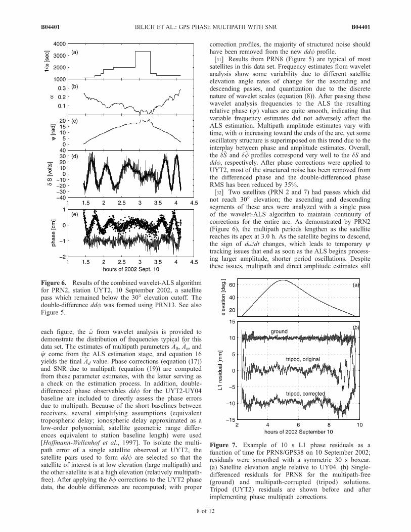
each figure, the w from wavelet analysis is provided todemonstrate the distribution of frequencies typical for thisdata set. The estimates of multipath parameters A0, Am andy come from the ALS estimation stage, and equation 16yields the final Ad value. Phase corrections (equation (17))and SNR due to multipath (equation (19)) are computedfrom these parameter estimates, with the latter serving asa check on the estimation process. In addition, double-differenced phase observables ddf for the UYT2-UY04baseline are included to directly assess the phase errorsdue to multipath. Because of the short baselines betweenreceivers, several simplifying assumptions (equivalenttropospheric delay; ionospheric delay approximated as alow-order polynomial; satellite geometric range differ-ences equivalent to station baseline length) were used[Hoffmann-Wellenhof et al., 1997]. To isolate the multi-path error of a single satellite observed at UYT2, thesatellite pairs used to form ddf are selected so that thesatellite of interest is at low elevation (large multipath) andthe other satellite is at a high elevation (relatively multipath-free). After applying the df corrections to the UYT2 phasedata, the double differences are recomputed; with proper
correction profiles, the majority of structured noise shouldhave been removed from the new ddf profile.[31] Results from PRN8 (Figure 5) are typical of most
satellites in this data set. Frequency estimates from waveletanalysis show some variability due to different satelliteelevation angle rates of change for the ascending anddescending passes, and quantization due to the discretenature of wavelet scales (equation (8)). After passing thesewavelet analysis frequencies to the ALS the resultingrelative phase (y) values are quite smooth, indicating thatvariable frequency estimates did not adversely affect theALS estimation. Multipath amplitude estimates vary withtime, with a increasing toward the ends of the arc, yet someoscillatory structure is superimposed on this trend due to theinterplay between phase and amplitude estimates. Overall,the dS and df profiles correspond very well to the dS andddf, respectively. After phase corrections were applied toUYT2, most of the structured noise has been removed fromthe differenced phase and the double-differenced phaseRMS has been reduced by 35%.[32] Two satellites (PRN 2 and 7) had passes which did
not reach 30� elevation; the ascending and descendingsegments of these arcs were analyzed with a single passof the wavelet-ALS algorithm to maintain continuity ofcorrections for the entire arc. As demonstrated by PRN2(Figure 6), the multipath periods lengthen as the satellitereaches its apex at 3.0 h. As the satellite begins to descend,the sign of dw/dt changes, which leads to temporary ytracking issues that end as soon as the ALS begins process-ing larger amplitude, shorter period oscillations. Despitethese issues, multipath and direct amplitude estimates still
Figure 6. Results of the combined wavelet-ALS algorithmfor PRN2, station UYT2, 10 September 2002, a satellitepass which remained below the 30� elevation cutoff. Thedouble-difference ddf was formed using PRN13. See alsoFigure 5.
Figure 7. Example of 10 s L1 phase residuals as afunction of time for PRN8/GPS38 on 10 September 2002;residuals were smoothed with a symmetric 30 s boxcar.(a) Satellite elevation angle relative to UY04. (b) Single-differenced residuals for PRN8 for the multipath-free(ground) and multipath-corrupted (tripod) solutions.Tripod (UYT2) residuals are shown before and afterimplementing phase multipath corrections.
B04401 BILICH ET AL.: GPS PHASE MULTIPATH WITH SNR
8 of 12
B04401

increase and decrease, respectively, toward the ends of thearc and result in large a at the lowest elevation angles.Although the reconstructed SNR profile matches the inputdS, the phase correction profile appears somewhat out-of-phase for the descending part of the arc. Even with thesedifficulties, the RMS of the double-differenced phase isreduced 31% by implementing the phase corrections asshown.
4.2. Positioning Results
[33] To assess the impact of multipath phase corrections,UYT2 solutions are contrasted before and after implement-ing corrections. Solutions computed with ground-mountedantennas, assumed to be multipath-free, are used as a targetfor ideal correction of carrier phase multipath at the tripod-mounted station. Two different solution types are analyzed:static positioning, where all data for the 10-h time periodyield a single position estimate and all residual error willappear in the postfit residuals, and kinematic positioning atthe data sample rate of 10 s, where phase error willpropagate into the position estimates.[34] When estimating a single position from all available
data, errors such as multipath are largely distributed to theresiduals; residuals from multipath-free and multipath-
corrupted solutions are compared to understand the magni-tude, frequency, and elevation angle dependence of phasemultipath error as it propagates into the position solution.An example from PRN8 illustrates the primary differencesbetween each solution’s residuals (Figure 7). Large-amplitude oscillations are observed in the UYT2 (tripod)residuals while the UYT1 (ground) residuals appear to belargely white noise with slight elevation angle dependenceof noise magnitude. Taking all residuals from the 10-h timeperiod together (Figure 8) establishes the dominant trends.The ground-mounted antennas have a relatively uniformroot-mean squared (RMS) error of 1.0–1.5 mm at allelevation angles. In contrast, the tripod-mounted antennaexperiences significant ground-bounce multipath error; thelargest amplitude errors occur at low elevation angles, withthe majority of the error below 30� elevation and a 40–170% increase in RMS relative to the ground residuals.[35] Implementing L1 multipath corrections for UYT2
phase data leads to substantial improvement of the residuals.The sinusoidal signatures are largely eliminated (Figures 7and 8) with a �19% reduction in RMS for data below 20�elevation and all satellites. The phase corrections success-fully reduce systematic errors in the residuals over 200–2000 s periods (Figure 9). However, some errors are stillpresent in the residuals after implementing the corrections,notably a non-zero trend over 10–20� which is notexplained by the single-reflector SNR multipath model.[36] Because the antennas were stationary during the
10-h site occupation, any non-zero measurements ob-served in positions estimated kinematically (at every epoch)are the result of unmodeled errors such as multipath. Forthe ground-mounted antennas, kinematic positions main-tain zero mean over the 10-h period with white noisecharacteristics over 20–2000 s periods in all components(Figure 10), thereby establishing a benchmark for multi-path-free positions. Positions for the antenna located 1.4 mabove the ground show large amplitude systematic errors inall components, with significant non-white power at >300 speriods, consistent with ground multipath for the givenantenna height. Incorporating phase multipath correctionsleads to encouraging levels of error reduction. In general,
Figure 8. Trends in L1 single-differenced phase residualsas a function of satellite elevation angle for multipath-free,multipath-corrupted, and multipath-corrected solutions. Allsatellites in view during the analysis period are included andsuperimposed. Tripod residuals refer to the UYT2-UY04baseline, whereas ground residuals come from the UYT1-UY04 solution. The bottom panel shows a histogram of theRMS of all residuals contained within a 5� bin for the threesolutions.
Figure 9. Mean power spectral density of the single-differenced L1 phase residuals before and after implement-ing L1 phase corrections to UYT2 data. Only residualsbelow 35� elevation are used (see Figure 8), and spectrafrom individual satellites are averaged.
B04401 BILICH ET AL.: GPS PHASE MULTIPATH WITH SNR
9 of 12
B04401
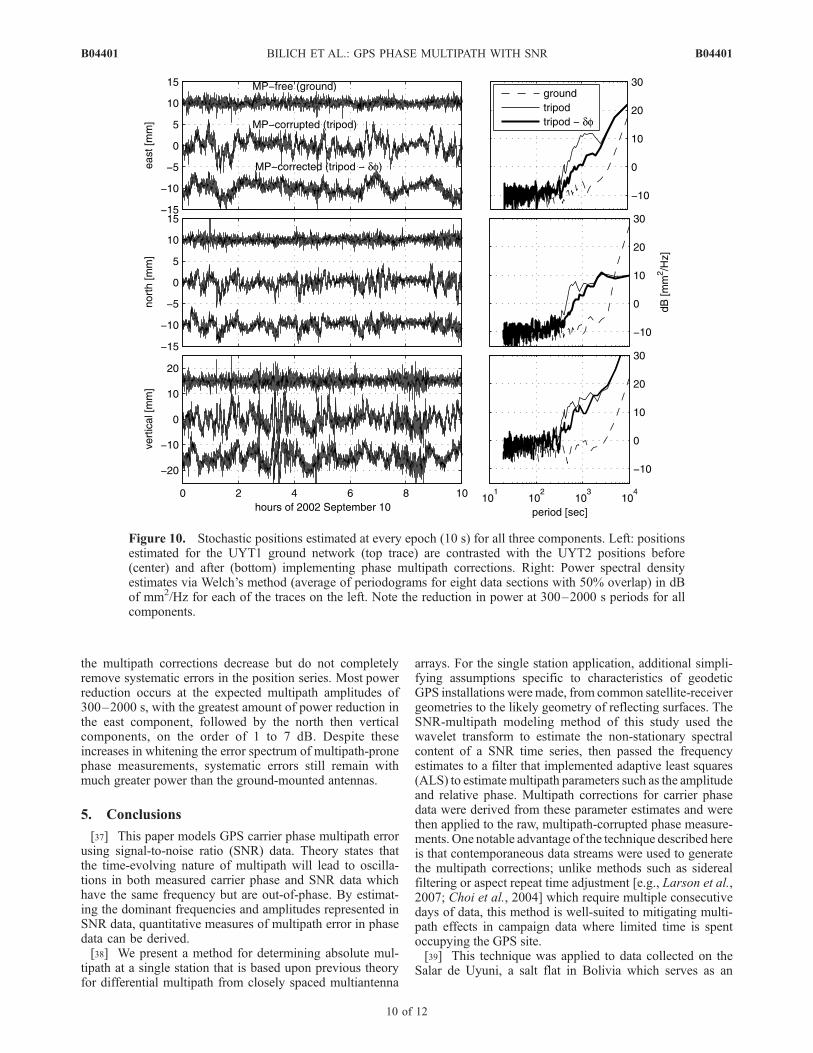
the multipath corrections decrease but do not completelyremove systematic errors in the position series. Most powerreduction occurs at the expected multipath amplitudes of300–2000 s, with the greatest amount of power reduction inthe east component, followed by the north then verticalcomponents, on the order of 1 to 7 dB. Despite theseincreases in whitening the error spectrum of multipath-pronephase measurements, systematic errors still remain withmuch greater power than the ground-mounted antennas.
5. Conclusions
[37] This paper models GPS carrier phase multipath errorusing signal-to-noise ratio (SNR) data. Theory states thatthe time-evolving nature of multipath will lead to oscilla-tions in both measured carrier phase and SNR data whichhave the same frequency but are out-of-phase. By estimat-ing the dominant frequencies and amplitudes represented inSNR data, quantitative measures of multipath error in phasedata can be derived.[38] We present a method for determining absolute mul-
tipath at a single station that is based upon previous theoryfor differential multipath from closely spaced multiantenna
arrays. For the single station application, additional simpli-fying assumptions specific to characteristics of geodeticGPS installations weremade, from common satellite-receivergeometries to the likely geometry of reflecting surfaces. TheSNR-multipath modeling method of this study used thewavelet transform to estimate the non-stationary spectralcontent of a SNR time series, then passed the frequencyestimates to a filter that implemented adaptive least squares(ALS) to estimate multipath parameters such as the amplitudeand relative phase. Multipath corrections for carrier phasedata were derived from these parameter estimates and werethen applied to the raw, multipath-corrupted phase measure-ments. One notable advantage of the technique described hereis that contemporaneous data streams were used to generatethe multipath corrections; unlike methods such as siderealfiltering or aspect repeat time adjustment [e.g., Larson et al.,2007; Choi et al., 2004] which require multiple consecutivedays of data, this method is well-suited to mitigating multi-path effects in campaign data where limited time is spentoccupying the GPS site.[39] This technique was applied to data collected on the
Salar de Uyuni, a salt flat in Bolivia which serves as an
Figure 10. Stochastic positions estimated at every epoch (10 s) for all three components. Left: positionsestimated for the UYT1 ground network (top trace) are contrasted with the UYT2 positions before(center) and after (bottom) implementing phase multipath corrections. Right: Power spectral densityestimates via Welch’s method (average of periodograms for eight data sections with 50% overlap) in dBof mm2/Hz for each of the traces on the left. Note the reduction in power at 300–2000 s periods for allcomponents.
B04401 BILICH ET AL.: GPS PHASE MULTIPATH WITH SNR
10 of 12
B04401

horizontal reflecting surface of large extent and negligibletopography with uniform reflecting characteristics. Con-trasting solutions before and after applying multipath cor-rections shows that phase errors are removed at periodsconsistent with ground multipath reflections, with a 20%reduction in postfit residuals RMS at low elevationangles (data <20� elevation) and reduced spectral powerin kinematic positions. This level of improvement isconsistent with earlier SNR modeling work using differ-ential arrays [e.g., Comp and Axelrad, 1997; Ray andCannon, 2001]. Although the amount of improvement isconsiderable, contrasting these multipath-corrected withmultipath-free solutions shows that the magnitude ofcorrections is insufficient to consider the correctedobservables ‘multipath-free’.[40] Although the ideal relationship between SNR and
phase multipath is well defined in theory, several factorslimit the applicability of the SNR phase multipath modelingtechnique in practice. Of primary importance, it is expectedthat most high quality receivers implement proprietarymultipath mitigation strategies at the tracking or observablecomputation phase. Multipath mitigation at the hardware orfirmware level would alter or negate the simplified SNR-multipath model proposed here. Similarly, we note thatother factors affect SNR and carrier phase but do not obeythe same relationships as multipath; if, for example, SNRoscillations due to antenna phase center variations orantenna gain pattern ripples were modeled as multipath-induced phenomena, implementing phase corrections wouldonly further corrupt position solutions. Likewise, the directand multipath components of SNR must be properly sepa-rated to avoid mistaking residual direct signal as multipath.Finally, a generalized version of this technique would haveto account for multiple reflecting objects of finite extent anddifferent orientations. To use the technique presented in thisstudy, these general environments would be separatelymodeled by iterations of the wavelet-ALS algorithm. Initialresearch into more complicated multipath environmentsindicates that contributions from multiple reflecting objectsmust have markedly different frequencies for wavelet-ALSiteration to be effective, a condition which is seldom met inactual antenna environments.[41] Additionally, SNR data quality will impact the effi-
cacy of the modeling process. The SNR data themselvesmust be estimated from the tracking loop outputs in such away that oscillations in SNR are of equivalent frequency tooscillations in the phase error. Each SNR value must also bereported with sufficient precision for spectral analysis toproperly resolve the constituent frequencies. However,experience with many stations, receiver models, and phasedata on different GPS frequencies shows this is not alwaysthe case [Bilich et al., 2007].[42] Our experience in applying this technique to addi-
tional stations and receiver types indicates that extractingmultipath amplitude and phase information from SNR timeseries is a difficult process requiring heavy levels of userinput, data editing, and careful station selection. Neverthe-less, the encouraging results from the Salar de Uyuni dataset suggest that if SNR of high precision and accuracy wereavailable on both frequencies for geodetic GPS sites, thismethod could potentially be useful for modeling and re-moving phase errors for simple multipath environments.
[43] Acknowledgments. The authors would like to thank AdrianBorsa for collecting and graciously providing the playa data set, andDuncan Agnew, John Langbein, and Christopher Comp for sharing theirvaluable spectral analysis knowledge. Wavelet software was provided byC. Torrence and G. Compo, and is available at URL http://paos.colorado.edu/research/wavelets/. This research was sponsored by a NSF grant onmultipath (EAR-000343) and a NSF graduate student research fellowship(AB). Reviews by Jim Davis and Clement Ogaja helped improve themanuscript.
ReferencesAltamimi, Z., P. Sillard, and C. Boucher (2002), ITRF2000: A new releaseof the international terrestrial reference frame for Earth science applica-tions, J. Geophys. Res., 107(B10), 2214, doi:10.1029/2001JB000561.
Axelrad, P., K. M. Larson, and B. Jones (2005), Use of the correct satelliterepeat period to characterize and reduce site-specific multipath errors,paper presented at ION GNSS 2005, Institute of Navigation, Long Beach,CA.
Bilich, A. L. (2006), Improving the precision and accuracy of geodeticGPS: Applications to multipath and seismology, Ph.D. dissertation, Uni-versity of Colorado, Boulder.
Bilich, A., and K. M. Larson (2007), Mapping the GPS multipath environ-ment using the signal-to-noise ratio (SNR), Radio Sci., 42, RS6003,doi:10.1029/2007RS003652.
Bilich, A., P. Axelrad, and K. M. Larson (2007), Scientific utility of thesignal-to-noise ratio (SNR) reported by geodetic GPS receivers, paperpresented at ION GNSS 2007, Institute of Navigation, Ft. Worth, TX.
Blewitt, G. (1989), Carrier phase ambiguity resolution for the Global Po-sitioning System applied to geodetic baselines up to 2000 km, J. Geo-phys. Res., 94, 10,187–10,203.
Bock, Y., R. Nikolaidis, and P. de Jonge (2000), Instantaneous geodeticpositioning at medium distances with the Global Positioning System,J. Geophys. Res., 105, 28,223–28,253, doi:10.1029/2000JB900268.
Borsa, A. A. (2005), Geomorphology of the salar de Uyuni, Boliva, Ph.D.dissertation, University of California, San Diego.
Borsa, A. A., J. B. Minster, B. G. Bills, and H. Fricker (2007), Modelinglong-period noise in kinematic GPS applications, J. Geod., 81, 157–170,doi:10.1007/s00190-006-0097-x.
Braasch, M. S. (1996), Multipath effects, in Global Positioning System:Theory and Applications, edited by B. W. Parkinson, J. J. Spilker Jr.,P. Axelrad, and P. Enge, vol. 1, chap. 14, American Institute ofAeronautics and Astronautics.
Choi, K., A. Bilich, K. M. Larson, and P. Axelrad (2004), Modified siderealfiltering: Implications for high-rate GPS positioning, Geophys. Res. Lett.,31, L22608, doi:10.1029/2004GL021621.
Comp, C. (1996), GPS carrier phase multipath characterization and a mi-tigation technique using the signal-to-noise ratio, Ph.D. dissertation, Uni-versity of Colorado, Boulder.
Comp, C., and P. Axelrad (1997), Adaptive SNR-based carrier phase multi-path mitigation technique, IEEE Trans. Aerosp. Electron. Syst., 34(1),264–276, doi:10.1109/7.640284.
Dow, J. M., R. E. Neilan, and G. Gendt (2005), The International GPSService (IGS): Celebrating the 10th anniversary and looking to the nextdecade, Adv. Space. Res., 36(3), 320 –326, doi:10.1016/j.asr.2005.05.125.
Elosegui, P., J. Davis, R. Jaldehag, J. Johansson, A. Niell, and I. Shapiro(1995), Geodesy using the Global Positioning System: The effects ofsignal scattering on estimates of site position, J. Geophys. Res., 100,9921–9934, doi:10.1029/95JB00868.
Georgiadou, Y., and A. Kleusberg (1988), On carrier signal multipath ef-fects in relative GPS positioning, Manuscr. Geod., 13, 172–179.
Gurtner, W. (1994), RINEX: The Receiver Independent Exchange format,GPS World, 5(7).
Hoffmann-Wellenhof, B., H. Lichtenegger, and J. Collins (1997), GPS:Theory and Practice, Springer-Verlag.
Kedar, S., G. Hajj, B. Wilson, and M. Heflin (2003), The effect of secondorder GPS ionospheric correction on receiver positions, Geophys. Res.Lett., 30(16), 1829, doi:10.1029/2003GL017639.
Kijewski, T., and A. Kareem (2002), On the presence of end effects andtheir melioration in wavelet-based analysis, J. Sound Vib., 256, 980–988,doi:10.1006/jsvi.2001.4227.
Larson, K. M., A. Bilich, and P. Axelrad (2007), Improving the precisionof high-rate GPS, J. Geophys. Res., 112, B05422, doi:10.1029/2006JB004367.
Lichten, S., and J. Border (1987), Strategies for high-precision GlobalPositioning System orbit determination, J. Geophys. Res., 92,12751–12762.
Mader, G. (1999), GPS antenna calibration at the National Geodetic Survey,GPS Solut., 3, 50–58, doi:10.1007/PL00012780.
B04401 BILICH ET AL.: GPS PHASE MULTIPATH WITH SNR
11 of 12
B04401

Meyers, S. D., B. Kelly, and J. O’Brien (1993), An introduction to waveletanalysis in oceanography and meteorology: With application to the dis-persion of Yanai waves, Mon. Weather Rev., 121, 2858 – 2866,doi:10.1175/1520-0493.
Ray, J. K. (2000), Mitigation of GPS code and carrier phase multipatheffects using a multi-antenna system, Ph.D. dissertation, University ofCalgary.
Ray, J. K., and M. E. Cannon (2001), Synergy between Global PositioningSystem code, carrier, and signal-to-noise ratio multipath errors, J.Guid.Control Dyn., 24, 54–63.
Reichert, A. (1999), Correction algorithms for GPS carrier phase multipathutilizing the signal-to-noise ratio and spatial correlation, Ph.D. disserta-tion, University of Colorado, Boulder.
Reichert, A., and P. Axelrad (1999), GPS carrier phase multipath reductionusing SNR measurements to characterize an effective reflector, paperpresented at ION GPS 1999, Institute of Navigation.
Springer, T., G. Beutler, and M. Rothacher (1998), A new solar radiationpressure model for the GPS satellites, GPS Solut., 2, 50–62, doi:10.1007/PL00012757.
Torrence, C., and G. Compo (1998), A practical guide to wavelet analysis,Bull. Am. Meteorol. Soc., 79, doi:10.1175/1520-0477.
�����������������������P. Axelrad and K. M. Larson, Department of Aerospace Engineering
Sciences, University of Colorado, Boulder, CO 80309-0429, USA.A. Bilich, National Geodetic Survey, NOAA, 325 Broadway, E/GC2,
Boulder, CO 80305, USA. ([email protected])
B04401 BILICH ET AL.: GPS PHASE MULTIPATH WITH SNR
12 of 12
B04401