modeling and validation of pipeline specificationsdutt/pubs/j38-prabhat-tecsfeb04.pdf ·...
TRANSCRIPT

Modeling and Validation of PipelineSpecifications
PRABHAT MISHRA and NIKIL DUTTUniversity of California, Irvine
Verification is one of the most complex and expensive tasks in the current Systems-on-Chip designprocess. Many existing approaches employ a bottom-up approach to pipeline validation, where thefunctionality of an existing pipelined processor is, in essence, reverse-engineered from its RT-levelimplementation. Our validation technique is complementary to these bottom-up approaches. Ourapproach leverages the system architect’s knowledge about the behavior of the pipelined archi-tecture, through architecture description language (ADL) constructs, and thus allows a powerfultop-down approach to pipeline validation. The most important requirement in top-down validationprocess is to ensure that the specification (reference model) is golden. This paper addresses auto-matic validation of processor, memory, and coprocessor pipelines described in an ADL. We presenta graph-based modeling that captures both structure and behavior of the architecture. Based onthis model, we present algorithms to ensure that the static behavior of the pipeline is well formedby analyzing the structural aspects of the specification. We applied our methodology to verify spec-ification of several realistic architectures from different architectural domains to demonstrate theusefulness of our approach.
Categories and Subject Descriptors: C.0 [Computer Systems Organization]: General—Modelingof computer architecture; C.0 [Computer Systems Organization]: General—Systems specifica-tion methodology; I.6.4 [Computing Methodologies]: Simulation and Modeling—Model valida-tion and analysis
General Terms: Verification, Algorithms, Design, Languages
Additional Key Words and Phrases: Modeling of processor pipeline, pipelined processor specifica-tion, pipeline validation, architecture description language
1. INTRODUCTION
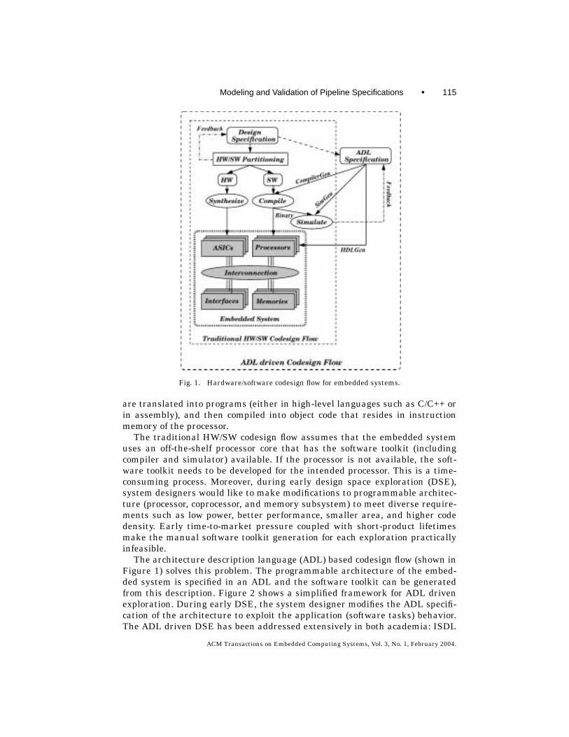
Traditional embedded systems consist of programmable processors, coproces-sors, application specific integrated circuits (ASIC), memories, and input/outputinterfaces. Figure 1 shows a traditional hardware/software codesign flow. Theembedded system is specified in a system design language. The specificationis then partitioned into tasks that are either assigned to software or hardware(ASIC) based on design constraints (cost, power, and performance). Tasks as-signed to hardware are translated into hardware description language (HDL)descriptions and then synthesized into ASICs. The tasks assigned to software
Authors’ address: Center for Embedded Computer Systems, 444 Computer Science, University ofCalifornia, Irvine, CA 92697-3430; email: [email protected] to make digital/hard copy of part of this work for personal or classroom use is grantedwithout fee provided that the copies are not made or distributed for profit or commercial advantage,the copyright notice, the title of the publication, and its date of appear, and notice is given thatcopying is by permission of the ACM, Inc. To copy otherwise, to republish, to post on servers, or toredistribute to lists requires prior specific permision and/or a fee.C© 2004 ACM 1539-9087/04/0200-0114 $5.00
ACM Transactions on Embedded Computing Systems, Vol. 3, No. 1, February 2004, Pages 114–139.
Modeling and Validation of Pipeline Specifications • 115
Fig. 1. Hardware/software codesign flow for embedded systems.
are translated into programs (either in high-level languages such as C/C++ orin assembly), and then compiled into object code that resides in instructionmemory of the processor.
The traditional HW/SW codesign flow assumes that the embedded systemuses an off-the-shelf processor core that has the software toolkit (includingcompiler and simulator) available. If the processor is not available, the soft-ware toolkit needs to be developed for the intended processor. This is a time-consuming process. Moreover, during early design space exploration (DSE),system designers would like to make modifications to programmable architec-ture (processor, coprocessor, and memory subsystem) to meet diverse require-ments such as low power, better performance, smaller area, and higher codedensity. Early time-to-market pressure coupled with short-product lifetimesmake the manual software toolkit generation for each exploration practicallyinfeasible.
The architecture description language (ADL) based codesign flow (shown inFigure 1) solves this problem. The programmable architecture of the embed-ded system is specified in an ADL and the software toolkit can be generatedfrom this description. Figure 2 shows a simplified framework for ADL drivenexploration. During early DSE, the system designer modifies the ADL specifi-cation of the architecture to exploit the application (software tasks) behavior.The ADL driven DSE has been addressed extensively in both academia: ISDL
ACM Transactions on Embedded Computing Systems, Vol. 3, No. 1, February 2004.

116 • Prabhat Mishra and Nikil Dutt
Fig. 2. ADL driven design space exploration.
[Hadjiyiannis et al. 1997], Valen-C [Inoue et al. 1998], MIMOLA [Leupers andMarwedel 1998], LISA [Zivojnovic et al. 1996], nML [Freericks 1993; Rajeshand Moona 1999], and industry: ARC [ARC ], Axys [Axys ], RADL [Siska 1998],Target [Target ], Tensilica [Tensilica ], MDES [Trimaran 1997]. The ADL spec-ification is used to generate software toolkit including compiler and simulatorto enable architectural exploration. The ADL specification has also been usedto generate hardware implementations for rapid system prototyping [Leupersand Marwedel 1998; Mishra et al. 2003; Schliebusch et al. 2002].
However, the validation of the ADL specification has not been addressedso far. It is important to validate the ADL description of the architecture toensure the correctness of both the architecture specified, as well as the gener-ated software toolkit and hardware implementation. The benefits of validationare twofold. First, the process of any specification is error prone and thus ver-ification techniques can be used to check for correctness and consistency ofspecification. Second, changes made to the processor during exploration mayresult in incorrect execution of the system and verification techniques can beused to ensure correctness of the modified architecture.
Furthermore, the validated ADL specification can be used as a golden refer-ence model for processor pipeline validation. One of the most important prob-lems in today’s processor design validation is the lack of a golden referencemodel that can be used for verifying the design at different levels of abstrac-tion. Thus, many existing validation techniques employ a bottom-up approachto pipeline verification, where the functionality of an existing pipelined proces-sor is, in essence, reverse engineered from its RT-level implementation. Ourvalidation technique is complementary to these bottom-up approaches. Our ap-proach leverages the system architects knowledge about the behavior of thepipelined processor, through ADL constructs, and thus allows a powerful top-down approach to pipeline validation.
In this paper, we present an automatic validation framework, driven byan ADL. A novel feature of our approach is the ability to model the pipelinestructure and behavior for the processor, coprocessor, as well as the memorysubsystem using a graph-based model. Based on this model, we present
ACM Transactions on Embedded Computing Systems, Vol. 3, No. 1, February 2004.

Modeling and Validation of Pipeline Specifications • 117
Fig. 3. ADL-driven validation and exploration flow.
algorithms to ensure that the static behavior of the pipeline is well formedby analyzing the structural aspects of the specification. Figure 3 shows the val-idation flow in our framework. In our ADL driven exploration flow, the designerstarts by describing the programmable architecture in an ADL. The graphmodel of the architecture can be generated automatically from this ADL de-scription. Several properties are applied to ensure that the architecture is wellformed. To enable rapid exploration, the software toolkit can be generated fromthis golden reference model and the feedback can be used to modify the ADLspecification of the architecture. We applied our methodology to verify pipelinespecification of several realistic architectures from different architectural do-mains (RISC, DSP, VLIW, and Superscalar) to demonstrate the usefulness of ourapproach.
The rest of the paper is organized as follows. Sections 2 and 3 present re-lated work addressing ADLs and validation of pipelined processors. Section 4presents a graph-based modeling of processor, memory, and coprocessorpipelines. Section 5 proposes several properties that must be satisfied for validpipeline specification. Section 6 illustrates validation of pipeline specificationsfor several realistic architectures. Finally, Section 7 concludes the paper.
2. ARCHITECTURE DESCRIPTION LANGUAGES
Traditionally, ADLs have been classified into two categories depending onwhether they primarily capture the behavior (instruction set) or the structure
ACM Transactions on Embedded Computing Systems, Vol. 3, No. 1, February 2004.

118 • Prabhat Mishra and Nikil Dutt
of the processor. Recently, many ADLs have been proposed that captures boththe structure and the behavior of the architecture.
nML [Freericks 1993] and ISDL [Hadjiyiannis et al. 1997] are examplesof behavior-centric ADLs. In nML, the processor’s instruction set is describedas an attributed grammar with the derivations reflecting the set of legalinstructions. The nML has been used by the retargetable code generation envi-ronment CHESS [Lanneer et al. 1995] to describe DSP and ASIP processors. InISDL, constraints on parallelism are explicitly specified through illegal opera-tion groupings. This could be tedious for complex architectures such as DSPs,that permit operation parallelism (e.g., Motorola 56K) and VLIW machineswith distributed register files (e.g., TI C6X). The retargetable compiler systemby Inoue et al. [1998] produces code for RISC architectures starting from aninstruction set processor description, and an application described in Valen-C.Valen-C is a C language extension supporting explicit and exact bit width forinteger type declarations, targeting embedded software. The processor descrip-tion represents the instruction set, but does not appear to capture resourceconflicts, and timing information for pipelining.
MIMOLA [Leupers and Marwedel 1998] is an example of an ADL that pri-marily captures the structure of the processor wherein the net-list of the targetprocessor is described in a HDL like language. One advantage of this approachis that the same description is used for both processor synthesis and code gen-eration. The target processor has a microcode architecture. The net-list de-scription is used to extract the instruction set [Leupers and Marwedel 1997]and produce the code generator. Extracting the instruction set from the struc-ture may be difficult for complicated instructions, and may lead to poor qualitycode. The MIMOLA descriptions are generally very low level and laborious towrite.
More recently, languages which capture both the structure and the behaviorof the processor, as well as detailed pipeline information (typically specifiedusing reservation tables) have been proposed. LISA [Zivojnovic et al. 1996] isone such ADL whose main characteristic is the operation-level description ofthe pipeline. RADL [Siska 1998] is an extension of the LISA approach that fo-cuses on explicit support of detailed pipeline behavior to enable generation ofproduction quality cycle-accurate and phase-accurate simulators. FLEXWARE[Paulin et al. 1994] and MDes [Trimaran 1997] have a mixed-level struc-tural/behavioral representation. FLEXWARE contains the CODESYN code-generator and the Insulin simulator for ASIPs. The simulator uses a VHDLmodel of a generic parameterizable machine. The application is translated fromthe user-defined target instruction set to the instruction set of this genericmachine.
The MDes [Trimaran 1997] language used in the Trimaran system is amixed-level ADL, intended for DSE. Information is broken down into sections(such as format, resource-usage, latency, operation, register, and so on), basedon a high-level classification of the information being represented. However,MDes allows only a restricted retargetablility of the simulator to the HPL-PD processor family. MDes permits the description of the memory system,but is limited to the traditional hierarchy (register files, caches, and so on).
ACM Transactions on Embedded Computing Systems, Vol. 3, No. 1, February 2004.
Modeling and Validation of Pipeline Specifications • 119
The EXPRESSION ADL [Halambi et al. 1999] follows a mixed-level approach(behavioral and structural) to facilitate automatic software toolkit generation,validation, HDL generation, and DSE for a wide range of programmable embed-ded systems. The ADL captures the structure, behavior, and mapping (betweenstructure and behavior) of the architecture.
3. RELATED WORK
An extensive body of recent work addresses architectural description languagedriven software toolkit generation and DSE for processor-based embedded sys-tems, as described in Section 2. The ADL specification has also been used togenerate hardware implementations for rapid system prototyping [Leupers andMarwedel 1998; Mishra et al. 2003; Schliebusch et al. 2002]. However, none ofthese approaches address the validation issue of the ADL specification. The val-idation is necessary to ensure the correctness of the generated software toolkitand hardware implementation. It is important to ensure that the referencemodel (specification) is golden, and it describes a well-formed architecture withintended execution style.
Several approaches for formal or semi-formal verification of pipelined pro-cessors have been developed in the past. Theorem proving techniques, for ex-ample, have been successfully adapted to verify pipelined processors [Cyrluk1993; Sawada and Hunt 1997, 1998; Srivas and Bickford 1990]. However, theseapproaches require a great deal of user intervention, especially for verifyingcontrol intensive designs. Hosabettu [2000] proposed an approach to decomposeand incrementally build the proof of correctness of pipelined microprocessorsby constructing the abstraction function using completion functions.
Burch and Dill [1994] presented a technique for formally verifying pipelinedprocessor control circuitry. Their technique verifies the correctness of the imple-mentation model of a pipelined processor against its instruction-set architec-ture (ISA) model based on quantifier-free logic of equality with uninterpretedfunctions. The technique has been extended to handle more complex pipelinedarchitectures by several researchers [Skakkebaek et al. 1998; Velev 2000; Velevand Bryant 2000]. The approach of Velev and Bryant [2000] focuses on effi-ciently checking the commutative condition for complex microarchitectures byreducing the problem to checking equivalence of two terms in a logic with equal-ity, and uninterpreted function symbols.
Huggins and Campenhout [1998] verified the ARM2 pipelined processor us-ing abstract state machine. Levitt and Olukotun [1997] presented a verificationtechnique, called unpipelining, which repeatedly merges last two pipe stagesinto one single stage, resulting in a sequential version of the processor. A frame-work for microprocessor correctness statements about safety that is indepen-dent of implementation representation and verification approach is presentedin Aagaard et al. [2001].
Ho et al. [1998] extract controlled token nets from a logic design to performefficient model checking. Jacobi [2002] used a methodology to verify out-of-order pipelines by combining model checking for the verification of the pipelinecontrol, and theorem proving for the verification of the pipeline functionality.
ACM Transactions on Embedded Computing Systems, Vol. 3, No. 1, February 2004.

120 • Prabhat Mishra and Nikil Dutt
Compositional model checking is used to verify a processor microarchitec-ture containing most of the features of a modern microprocessor [Jhala andMcMillan 2001]. There has been a lot a work in the area of module level vali-dation, such as verification of floating-point unit [Ho et al. 1996], and protocolvalidation, such as verification of cache coherence protocol [Pong and Dubois1997].
All the above techniques attempt to formally verify the implementation ofpipelined processors by comparing the pipelined implementation with its se-quential (ISA) specification model, or by deriving the sequential model fromthe implementation. Our validation technique is complementary to these for-mal approaches. We define a set of properties that have to be satisfied for thecorrect pipeline behavior. We apply these properties to ensure that the staticbehavior of the pipeline is well formed by analyzing the structural aspects ofthe specification using a graph-based model. Currently, we are developing tech-niques to verify the dynamic behavior by analyzing the instruction flow in thepipeline using a finite state machine based model to validate several architec-tural properties, such as determinism and execution style, in the presence ofhazards and exceptions [Mishra and Dutt 2002; Mishra et al. 2002].
4. ARCHITECTURE PIPELINE MODELING
We present a graph-based modeling of architecture pipelines that captures boththe structure and the behavior. The graph model presented here can be derivedfrom a pipeline specification of the architecture described in an ADL, for ex-ample, EXPRESSION [Halambi et al. 1999]. This graph model can captureprocessor, memory, and coprocessor pipelines for wide variety of architectures,namely, RISC, DSP, VLIW, Superscalar, and Hybrid architectures. Note that it isimportant to capture the memory pipeline along with processor and coprocessorpipelines, since any memory operation exercises both the processor and mem-ory pipeline structures [Mishra et al. 2001]. In this section, we briefly describehow we model the structure and behavior of an architecture. We also model themapping functions between structure and behavior.
4.1 Structure
The structure of an architecture pipeline is modeled as a graph GS
GS = (VS , ES). (1)
VS denotes a set of components in the architecture. VS consists of four types ofcomponents
VS = Vunit ∪ Vstorage ∪ Vport ∪ Vconnection (2)
where Vunit is a set of units (e.g., ALUs), Vstorage a set of storages (e.g., registerfiles, caches), Vport a set of ports, and Vconnection a set of connections (e.g., buses).ES consists of two types of edges
ES = Edata transfer ∪ Epipeline (3)
ACM Transactions on Embedded Computing Systems, Vol. 3, No. 1, February 2004.

Modeling and Validation of Pipeline Specifications • 121
Fig. 4. A structure graph of a simple architecture.
where Edata transfer is a set of data-transfer edges and Epipeline is a set of pipelineedges.
Edata transfer ⊆ Vunit × Vport
∪ Vstorage × Vport
∪ Vport × Vconnection
∪ Vconnection × Vport
∪ Vport × Vunit
∪ Vport × Vstorage (4)Epipeline ⊆ Vunit × Vunit. (5)
A data-transfer edge (v1, v2) ∈ Edata transfer indicates connectivity between twocomponents v1 and v2. Data are transferred from one component to anothervia data-transfer edges. A pipeline edge specifies the ordering of units com-prising the pipeline stages (or simply pipe-stages). Intuitively, operations flowfrom pipe-stages to pipe-stages through pipeline edges. Both pipeline edges anddata-transfer edges are unidirectional. Bidirectional data-transfers are mod-eled using two edges of different directions.
For illustration, we use a simple multi-issue architecture consisting of aprocessor, a coprocessor, and a memory subsystem. Figure 4 shows the graph-based model of this architecture that can issue up to three operations (an ALUoperation, a memory access operation, and a coprocessor operation) per cycle. Inthe figure, normal boxes denote units, dotted boxes are storages, small circlesare ports, shaded boxes are connections, bold edges are pipeline edges, and
ACM Transactions on Embedded Computing Systems, Vol. 3, No. 1, February 2004.

122 • Prabhat Mishra and Nikil Dutt
Fig. 5. A fragment of the behavior graph.
dotted edges are data-transfer edges. For ease of illustration, we have shownonly few ports and connections. Each component has several attributes. Thefigure shows only two of them, namely, capacity and timing for some of the nodes.The capacity denotes the maximum number of operations which the componentcan handle in a cycle, while the timing denotes the number of cycles takenby the component to execute them. A path from a root node (e.g., Fetch unit)to a leaf node (e.g., WriteBack unit) consisting of units and pipeline edges iscalled a pipeline path. Intuitively, a pipeline path denotes an execution flow inthe pipeline taken by an operation. For example, one of the pipeline path is{Fetch, Decode, ALU1, ALU2, WriteBack}. A path from a unit to main memoryor register file consisting of storages and data-transfer edges is called a data-transfer path. For example, {MemCntrl, L1, L2, MainMemory} is a data-transferpath. A memory operation traverses different data-transfer paths depending onwhere it gets the data in the memory. For example, a load operation which is hitin L2 will traverse the path (includes pipeline and data-transfer paths) {Fetch,Decode, AddrCalc, MemCntrl, L1, L2(hit), L1, MemCntrl, WriteBack}. Similarly,a coprocessor operation will traverse the path {Fetch, Decode, CP 1, EMIF 1,CoProc, CP 2, EMIF 2}. However, in this path we have not shown different datatransfers. For example, EMIF 1 sends read request to DMA and DMA writesdata in coprocessor local memory which coprocessor uses during computation.The coprocessor writes the result back to local memory and finally EMIF 2requests DMA to write the result back to main memory.
4.2 Behavior
The behavior of an architecture is a set of operations that can be executed onthe architecture. Each operation in turn consists of a set of fields (e.g., opcode,arguments) that specify, at an abstract level, the execution semantics of theoperation. We model the behavior as a graph GB, consisting of nodes VB andedges EB.
GB = (VB, EB). (6)
The nodes represent the fields of each operation, while the edges representorderings between the fields. The behavior graph GB is a set of disjointed sub-graphs, and each subgraph is called an operation graph (or simply an operation).Figure 5 describes a portion of the behavior (consisting of two operation graphs)for the example processor in Figure 4.
ACM Transactions on Embedded Computing Systems, Vol. 3, No. 1, February 2004.

Modeling and Validation of Pipeline Specifications • 123
Nodes are of two types: Vopcode is a set of opcode nodes that represent theopcode (i.e., mnemonic), and Vargument is a set of argument nodes that representargument fields (i.e., source and destination arguments). Each operation graphmust have one opcode node. In Figure 5, the ADD and LD nodes are opcodenodes, while the others are argument nodes.
VB = Vopcode ∪ Vargument (7)EB = Eoperation ∪ Eexecution (8)
Edges between the nodes are also of two types. Both types of edges are unidirec-tional. Eoperation is a set of operation edges that link the fields of the operationand also specify the syntactical ordering between them. For each operationgraph, operation edges must construct a path containing an opcode node. Onthe other hand, Eexecution is a set of execution edges that specify the executionordering between the argument nodes:
Eoperation ⊆ Vopcode × Vargument
∪ Vargument × Vargument (9)Eexecution ⊆ Vargument × Vargument. (10)
There must be no cycles consisting of execution edges. In Figure 5, the solidedges represent operation edges while the dotted edges represent executionedges. For the ADD operation, the operation edges specify that the syntacticalordering is opcode followed by ADD SRC1, ADD SRC2 and ADD DST argu-ments (in that order) and the execution edges specify that the ADD SRC1 andADD SRC2 arguments are executed (i.e., read) before the ADD DST argumentis executed (i.e., written).
4.3 Mapping between Structure and Behavior
An important component of our graph model is a set of functions that correlatethe abstract, high-level behavioral model of the architecture to the structuralmodel. We define a set of useful mapping functions that map nodes in thestructure to nodes in the behavior (or vice-versa). The unit-to-opcode (opcode-to-unit) mapping is a bidirectional function that maps unit nodes in the structureto opcode nodes in the behavior. It defines, for each functional unit, the set ofoperations supported by that unit (and vice versa).
funit–opcode : Vunit → Vopcode (11)fopcode–unit : Vopcode → Vunit (12)
For the example processor in Figure 4, the funit–opcode mappings include map-pings from Fetch unit to opcodes {ADD, LD} , ALU unit to opcode ADD, AddrCalcunit to opcode LD, and so on.
The argument-to-storage (storage-to-argument) mapping is a bidirectionalfunction that maps argument nodes in the behavior to storage nodes in thestructure. It defines, for each argument of an operation, the storage location
ACM Transactions on Embedded Computing Systems, Vol. 3, No. 1, February 2004.
124 • Prabhat Mishra and Nikil Dutt
that the argument resides in.
fargument–storage : Vargument → Vstorage (13)fstorage–argument : Vstorage → Vargument (14)
The fargument–storage mappings for the LD operation (Figure 5) are mappings fromLD SRC1 to RegisterFile, from LD SRC MEM to L1 (Data Memory), and fromLD DST to RegisterFile.
The port-to-argument (argument-to-port) mapping is a bidirectional functionthat maps port nodes in the structure to argument nodes in the behavior. Itdefines, for each port, the arguments that access it.
fport–argument : Vport → Vargument (15)fargument–port : Vargument → Vport (16)
The fargument–port mappings for the LD operation (Figure 5) are mappings fromLD SRC1 to port p4, from LD SRC MEM to port p7, and from LD DST to p1.
Each functional unit (with read or write ports) supports certain data-transferoperations. This can be derived from the above three mapping functions. Forexample, the Decode unit of Figure 4 supports register read (regRead) forADD and LD opcodes; the MemCntrl supports data read (dataRead) and datawrite (dataWrite) from L1 data cache; the Fetch unit supports instruction read(instRead) from L1 instruction cache; the WriteBack unit supports register write(regWrite). Each storage supports certain data-transfer operations. For exam-ple, the RegisterFile of Figure 4 supports regRead and regWrite; L1 data cachesupports dataRead and dataWrite, and so on.
We can generate a graph-model of the architecture from an ADL descrip-tion that has information regarding architecture’s structure, behavior, and themapping between structure and behavior. We have chosen the EXPRESSIONADL [Halambi et al. 1999] since it captures all the necessary information. Wegenerate automatically the graph model of the architecture pipeline consistingof structure graph, behavior graph, and mapping between them using the mod-eling techniques described above. Further details on graph model generationcan be found in Mishra et al. [2001].
5. ARCHITECTURE PIPELINE VERIFICATION
Based on the graph model presented in the previous section, specification ofarchitecture pipelines written in an ADL can be validated. In this section, wedescribe some of the properties used in our framework for validating pipelinespecification of the architecture.
5.1 Connectedness Property
The connectedness property ensures that each component must be connected toother component(s). As pipeline and data-transfer paths are connected regionsof the architecture, this property holds if each component belongs to at least
ACM Transactions on Embedded Computing Systems, Vol. 3, No. 1, February 2004.

Modeling and Validation of Pipeline Specifications • 125
one pipeline or data-transfer path.
∀vcomp ∈ VS , (∃GPP ∈ GPP, s.t. vcomp ∈ GPP)∨(∃GDP ∈ GDP, s.t. vcomp ∈ GDP) (17)
where GPP is a set of pipeline paths and GDP is a set of data-transfer paths.Algorithm 1 presents the pseudo code for verifying connectedness property.
The algorithm requires the graph model G of the architecture as input. It also
Algorithm 1: Verify ConnectednessInputs: i. Graph model of the architecture G
ii. ListOfUnits: list of units in the graph Giii. ListOfPorts: list of ports in the graph Giv. ListOfConnections: list of connections in the graph Gv. ListOfStorages: list of storages in the graph G
Outputs: i. True, if the graph model satisfies this property else false.ii. In case of failure, print the components which are not connected.
BeginUnmark all the entries in all the input lists.InsertQ(root, Q) /* Put root node of G in queue Q */while Q is not empty
Node n = DeleteQ(Q) /* Remove the front element of queue Q */Mark n as visited in Gcase type of node n
unit: Mark n in ListOfUnitsfor each port p in n
/* Insert p in the rear end of queue Q */if p is not visited, InsertQ(p, Q) endif
endforfor each children unit u of n
if u is not visited, InsertQ(u, Q) endifendfor
port: Mark n in ListOfPortsfor each connection c in n
if c is not visited InsertQ(c, Q) endifendforfor each storage s associated with n
if s is not visited InsertQ(s, Q) endifendforfor each unit u associated with n
if u is not visited InsertQ(u, Q)endfor
connection: Mark n in ListOfConnectionsfor each port p in n
if p is not visited InsertQ(p, Q) endifendfor
storage: Mark n in ListOfStoragesfor each port p in n
if p is not visited InsertQ(p, Q) endifendfor
endcaseendwhileReturn true if all the entries are marked in all of the input lists;
false otherwise, and print the unmarked components.End
ACM Transactions on Embedded Computing Systems, Vol. 3, No. 1, February 2004.

126 • Prabhat Mishra and Nikil Dutt
Fig. 6. An example processor with false pipeline paths.
requires all the component (unit, storage, port, and connection) lists as input.The first step is to unmark the entries in all the input lists. Each input list con-tains all the respective components in the graph. For example, the ListOfPortscontains all the ports in the graph G. Next, the graph is traversed in breadth-first manner and the visited components are marked. For example, when theunit u is visited during traversal, it is marked in ListOfUnits. Finally, the algo-rithm returns true if all the entries are marked in all the input lists. It returnsfalse if there are any unmarked entries in any of the input lists and it printsthem.
Each node of the graph is visited only once. The time and space complexityof the algorithm is O(n), where n is the number of nodes in the graph G. Eachnode of the graph can be one of the four components: unit, storage, port, orconnection.
5.2 False Pipeline and Data-Transfer Paths
According to the definition of pipeline paths, there may exist pipeline paths thatare never activated by any operation. Such pipeline paths are said to be false.For example, let us use another architecture shown in Figure 6 that executestwo operations: ALU-shift (alus) and multiply-accumulate (mac). This processorhas unit-to-opcode mappings between ALU unit and opcode alus, between SFTand alus, between MUL and mac, and between ACC and mac. Also, there areunit-to-opcode mappings between each of {IFD, RD1, RD2, WB} and alus, andeach of {IFD, RD1, RD2, WB} and mac. This processor has four pipeline paths:{IFD, RD1, ALU, RD2, SFT, WB}, {IFD, RD1, MUL, RD2, ACC, WB}, {IFD, RD1,ALU, RD2, ACC, WB}, and {IFD, RD1, MUL, RD2, SFT, WB}. However, the lasttwo pipeline paths cannot be activated by any operation. Therefore, they are
ACM Transactions on Embedded Computing Systems, Vol. 3, No. 1, February 2004.

Modeling and Validation of Pipeline Specifications • 127
Fig. 7. An example processor with false data-transfer paths.
false pipeline paths. Since these false pipeline paths may become false pathsdepending on the detailed structure of RD2, they should be detected at a higherlevel of abstraction to ease the later design phases.
From the view point of systems-on-chip (SOC) architecture exploration, wecan view the false pipeline paths as an indication of potential behaviors thatare not explicitly defined in the ADL description. This means that further cost,performance, and power optimizations may be possible if new instructions areadded to activate the false pipeline paths.
Formally, a pipeline path GPP(VPP, EPP) is false if intersection of opcodessupported by the units in the pipeline path is empty.
⋂
vunit∈VPP
funit–opcode(vunit) = φ. (18)
Similarly, there may exist data-transfer paths in the specification that arenever activated by any operation. Such data-transfer paths are said to be false.For example, let us use another architecture shown in Figure 7 which has sevenpossible data-transfer operations: integer-register-read (IregRd), float-register-read (FregRd), integer-register-write (IregWr), float-register-write (FregWr),load-data-from-memory (ldData), load-instruction-from-memory (ldInst), andstore-data-in-memory (stData). The Decode (ID) unit has mappings for IregRdand FregRd. There are mappings between each of {WB1, WB2} and {IregWr,FregWr}, each of {IF, L1I, ISB} and ldInst, each of {LDST, L1D, DSB} and{ldData, stData}, and each of {L2, DRAM} and {ldData, stData, ldInst}. Thisprocessor has ten data-transfer paths: {IRF, ID}, {FRF, ID}, {WB1, IRF}, {WB1,FRF}, {WB2, IRF}, {WB2, FRF}, {IF, L1I, L2, ISB, DRAM}, {LDST, L1D, L2,DSB, DRAM}, {IF, L1I, L2, DSB, DRAM}, {LDST, L1D, L2, ISB, DRAM} . How-ever, the last two data-transfer paths cannot be activated by any operation.Therefore, they are false data-transfer paths. If ALU1 supports only floating-point operations, the fourth path ({WB1, IRF}) becomes false data-transfer path.
ACM Transactions on Embedded Computing Systems, Vol. 3, No. 1, February 2004.

128 • Prabhat Mishra and Nikil Dutt
Formally, a data-transfer path GDP(VDP, EDP) is false if intersection of data-transfer operations supported by the units and storages ( fnode−operation) in thedata-transfer path is empty:
⋂
vnode∈VDP
fnode–operation(vnode) = φ. (19)
Algorithm 2 presents the pseudocode for verifying false pipeline and data-transfer paths. The algorithm requires the graph model G as input. It traversesthe graph in depth-first manner along each pipeline and data-transfer path.Each unit u has a list of supported opcodes SuppOpListu. Each node n (unitor storage) also maintains four temporary lists: OutOpListn, OutDTopListn,InOpListn, and InDTopListn. The OutOpListn is the list of opcodes producedby unit n and sent to its children units. The OutDTopListn is the list of data-transfer operations produced by node (unit or storage) n and sent to its childrenstorages. The InOpListn is the list that is used by unit n to copy the OutOpListp,the output list of the recently visited parent p. Similarly, the InDTopListn is thelist that is used by storage n to copy the OutDTopListp, the output list of therecently visited parent p. Each unit n performs intersection of InOpListn andSuppOpListn and send the result OutOpListn to its children units. If OutOpListnis empty, all the pipeline paths that use the path from n to root (via recentlyvisited parents) are false pipeline paths. A unit with read or write ports com-putes data-transfer operations using the method described in Section 4.3. Astorage computes OutDTopListn by performing intersection of SuppDTopListnand the input list InDTopListn. If OutDTopListn is empty, all the data-transferpaths that use the path from storage n to any unit via recently visited parentsare false data-transfer paths. The algorithm returns true if there are no falsepipeline or data-transfer paths. It returns false if there are any false pipelineor data-transfer paths and prints them.
If there are n nodes, x pipeline and data-transfer paths in the graph and thenumber of opcodes supported by the processor is p then the time complexity ofthis algorithm is O(x × n × (x + p log p)) and space complexity is O(n × p). Theopcode list in each node is a sorted list.
5.3 Completeness Property
The completeness property confirms that all operations must be executable. Anoperation op is executable if there exists a pipeline path GPP(VPP, EPP) on whichop is executable. An operation op is executable on a pipeline path GPP(VPP, EPP)if both conditions (a) and (b) hold.
(a) All units in VPP support the opcode op. More formally, the following condi-tion holds where vopcode is the opcode of the operation op:
∀vunit ∈ VPP, vopcode ∈ funit–opcode(vunit). (20)
(b) There are no conflicting partial ordering of operation arguments and unitports. Let V be a set of argument nodes of op. There are no conflictingpartial ordering of operation arguments and unit ports if, for any two nodes
ACM Transactions on Embedded Computing Systems, Vol. 3, No. 1, February 2004.

Modeling and Validation of Pipeline Specifications • 129
Algorithm 2: Verify False Pipeline and Data-transfer PathsInput: Graph model of the architecture G.Outputs: i. True, if the graph model satisfies this property else false.
ii. In case of failure, print the list of false pipeline and data-transfer paths.Begin
Push(root, S); FalsePPpathList = {}; FalseDPpathList = {} // Push root on stack Swhile S is not empty
Node n = Pop(S); Mark n as visited /* Pop the top element of stack S */case node type of n
unit: if n is the root nodeOutOpListn = SuppOpListn /* Send OutListn to its children */
else// Input list of n is the output list of the recently visited parent pInOpListn = OutOpListp/* Intersection of input list & supported opcode list */OutOpListn = SuppOpListn ∩ InOpListn
endifif n has read or write ports
OutDTopListn = ComputeDataTransferOps(OutOpListn)if OutDTopListn is empty
for all the data-transfer paths fDP from n to any leaf nodesInsert fDP in FalseDPpathList.
endforelse
for each children storage node st of n, Push(st, S) endforendif
endifif OutOpListn is empty
Record the pipeline path pp from n by tracingrecently visited parents till rootfor all pipeline paths ppEnd from n to any leaf nodes
Append ppEnd to pp to generate false pipeline path fPP.Insert fPP in FalsePPpathList.
endforelse
for each children unit u of n, Push(u, S) endforendif
storage: InDTopListn = OutDTopListpOutDTopListn = SuppDTopListn ∩ InDTopListnif OutDTopListn is empty
Record the data-transfer path dp from n by tracingrecently visited parents till any unitfor all data-transfer paths dpEnd from n to any leaf nodes
Append dpEnd to dp to generate false data-transfer pathfDP. Insert fDP in FalseDPpathList.
endforelse
for each children storage node st of n, Push(st, S) endforendif
endcaseendwhileif FalsePPpathList and FalseDPpathList are empty return true;else return false and print FalsePPpathList and FalseDPpathList.endif
End
ACM Transactions on Embedded Computing Systems, Vol. 3, No. 1, February 2004.

130 • Prabhat Mishra and Nikil Dutt
v1, v2 ∈ V such that (v1, v2) ∈ Eexecution, all the following conditions hold:� There exists a data-transfer path from a storage farg–storage(v1) to a unit
vu1 in VPP through a port farg–port(v1).� There exists a data-transfer path from a unit vu2 in VPP to a storage
farg–storage(v2) through a port farg–port(v2).� vu1 and vu2 are the same unit or there is a path consisting of pipeline
edges from vu1 to vu2.
For example, let us consider the ADD operation for the processor describedin Figures 4 and 5. To satisfy the condition (a), Fetch, Decode, ALU1, ALU2,and WriteBack units must have mappings to the ADD opcode. On the otherhand, the condition (b) is satisfied because the structure has data-transfer pathsfrom RegisterFile to Decode and from WriteBack to RegisterFile, and there isa pipeline path from Decode to WriteBack.
Algorithm 3 presents the pseudocode for verifying completeness property.The algorithm requires the graph model G and the list of operations OpList asinput. It traverses the graph in depth-first manner for each operation op andidentify all the pipeline paths pp that support op. All the units n in the pipelinepath should have op in their supported opcode list SuppOpListn. The pipelinepath pp must have units that can read the source operands of op and writethe destination operands of op in correct order. If all the conditions are met, opis executable in pipeline path pp and op is marked in OpList. The algorithmreturns true if all the entries in OpList are marked. It returns false if there areunmarked entries and prints them.
Algorithm 3: Verify CompletenessInputs: i. Graph model G of the architecture.
ii. The list of operations OpList supported by the architecture.Outputs: i. True, if the graph model satisfies this property else false.
ii. In case of failure, print the list of operations that are not executable.Begin
for each operation op supported by the architectureopSrcList = list of sources in the operation op.opDestList = list of destinations in the operation op.Push(root, S) /* Put root node of G in stack S */while S is not empty
Node n = Pop(S) /* Remove the top element of S */Mark n as visited in G.if op ∈ SuppOpListn /* op is supported by unit n */
for each port p of nif p is a read or read-write port
for each unmarked source src in opSrcListif src can be read via p, mark src in opSrcList with (p, n)endif
endforendifif p is a write or read-write port
for each unmarked destination dest in opDestListif dest can be written via p
mark dest in opDestList with (p, n)endif
endfor
ACM Transactions on Embedded Computing Systems, Vol. 3, No. 1, February 2004.

Modeling and Validation of Pipeline Specifications • 131
endifendforif unit n is a leaf node
if ((all the sources in opSrcList are marked) and(all the nodes r that read the sources are in expected order)and (all the destinations in opDestList are marked) and(all the nodes w that write the destinations are in expected
order)and (all the nodes r and w are in the same pipeline path
and r appears before w))Mark op in OpList /* this path supports op */break /* one pipeline path is sufficient, exit while loop */
endifelse
for each children unit u of n, Push(u, S) endforendif
endwhileendforReturn true if all the entries in OpList are marked;
false otherwise, and print the unmarked entries in OpList.End
If there are n nodes, x pipeline and data-transfer paths in the graph and thenumber of opcodes supported by the architecture is p then the time complexityof this algorithm is O(x × n × p × log p) and space complexity is O(n × p). Theopcode list in each unit is a sorted list.
5.4 Finiteness Property
The finiteness property guarantees the termination of any operation executedthrough the pipeline. The termination is guaranteed if all pipeline and data-transfer paths except false pipeline and data-transfer paths have finite lengthand all nodes on the pipeline or data-transfer paths have finite timing.
The length of a pipeline or data-transfer path is defined as the number ofstages required to reach the final (leaf) nodes from the root node of the graph.
∃K , s.t. ∀path ∈ (GPP, GDP), num stages(path) < K (21)
Here, num stages is a function that, given a pipeline or data-transfer path,returns the number of stages (i.e., clock cycles) required to execute it. In thepresence of cycles in the pipeline path, this function cannot be determined fromthe structural graph model alone. However, if there are no cycles in the pipelinepaths, the termination property is satisfied if the number of nodes in VS is finite,and each multi-cycle component has finite timing.
Algorithm 4 presents the pseudocode for verifying finiteness property. Thealgorithm requires the graph model G and the list of operations OpList as input.It traverses the graph in depth-first manner for each operation op and identifyall the pipeline paths op–pp that support op. For each opcode it colors differentpipeline paths op–pp with different color. A cycle is detected if the same colorednode is visited more than once during traversal. The pipeline path op–pp withcycle will be stored in PathList. This property is also violated when there arepaths that are longer than MaxPathLength or when the execution time needed
ACM Transactions on Embedded Computing Systems, Vol. 3, No. 1, February 2004.

132 • Prabhat Mishra and Nikil Dutt
Algorithm 4: Verify FinitenessInputs: i. Graph model G of the architecture.
ii. The list of operations OpList supported by the architecture.Outputs: i. True, if the graph model satisfies this property else false.
ii. In case of failure, prints the list of pipeline and data-transfer pathsthat violates this property.
BeginPathList = {};for each operation op supported by the architecture
PathLength = 0;Push(< root, PathLength >, S); /* Put root node and PathLength on stack S */Unmark all the nodes in graph G;ColorCode = 0;while S is not empty
/* Remove the top element (node and PathLength pair) of S */< n, PathLength > = Pop(S)if op ∈ SuppOpListn /* op is supported by unit n */
PathLength = PathLength + 1;timing = GetExecutionTime(op, n);if ((n is already marked with ColorCode) or
(timing is greater than MaxExecutionTime) or(PathLength is greater than MaxPathLength))
/* Insert path with nodes marked using ColorCode */Insert < op, path > pair in PathListbreak; /* exit while loop */
elseMark n with ColorCodeif unit n is a leaf node
ColorCode = ColorCode + 1;else
for each children node child of nPush(< child, PathLength >, S);
endforendif
endifelse
ColorCode = ColorCode + 1;endif
endwhileendforReturn true if PathList is empty
false otherwise, and print PathList.End
by op in any node in that path is greater than MaxExecutionTime. The algorithmreturns true if PathList is empty. It returns false if there are entries in PathListand prints them.
Our finiteness algorithm assumes that there are no cycles in the pipeline.If the cycles are allowed in the pipeline due to the reuse of the resources, ouralgorithm needs to be modified. Let us assume, a resource is reused by anoperation op for nop times. We can modify the algorithm to check for “alreadymarked with ColorCode for nop times” instead of checking “already marked withColorCode” for the operation op.
ACM Transactions on Embedded Computing Systems, Vol. 3, No. 1, February 2004.

Modeling and Validation of Pipeline Specifications • 133
If there are n nodes, x pipeline and data-transfer paths in the graph and thenumber of opcodes supported by the architecture is p then the time complexityof this algorithm is O(x × n × p × log p) and space complexity is O(n × p). Theopcode list in each unit is a sorted list.
5.5 Architecture-Specific Properties
The architecture must be well formed based on the original intent of the archi-tectural model. To verify the validity of this property we need to verify severalarchitectural properties. Here we mention some of the architectural propertieswe verify in our framework.
— The number of operations processed per cycle by a unit cannot be smallerthan the total number of operations sent by its parents unless the unit has areservation station. This is not an error if that specific unit kills certain oper-ations based on certain conditions, for example, killing no operation (NOP).
— There should be a path from an execution unit supporting branch opcodesto program counter (PC) or Fetch unit to ensure that PC is modified in caseof branch misprediction.
— The instruction template should match available pipeline bandwidth.However, this is not an error because a machine with n operations in ainstruction and m (> n) parallel pipeline paths may have many multicycleunits. Similarly, the architecture may have m (< n) parallel pipeline pathsif it has reservation station and instruction fetch timing is large.
— There must be a path from load/store unit to main memory via storagecomponents to ensure that every memory operation is complete.
— The address space used by the processor must be equal to the union ofaddress spaces covered by memory subsystem (SRAM, cache hierarchies,and so on) to ensure that all the memory accesses can complete.
These are only some of the properties we currently verify in our framework.For every architecture with new architectural features we can easily add andverify new properties for those features.
We first verify finiteness property before applying any other properties in ourframework. If there are paths with infinite length and timing, the finitenessalgorithm will display the path and exit. Next, we apply the connectednessproperty followed by the false pipeline and data-transfer path property. Theremaining properties can be applied in any order. Algorithm 5 shows how weapply these properties in our framework.
Algorithm 5: Verify Architecture SpecificationInput: Graph model G of the architecture.Output: True, if the graph model satisfies all the properties else false.Begin
status = VerifyFiniteness (G, G.SupportedOpcodeList);if (status == false) {
Print the paths that violates this property;Return false;
}ACM Transactions on Embedded Computing Systems, Vol. 3, No. 1, February 2004.

134 • Prabhat Mishra and Nikil Dutt
status = VerifyConnectedness (G, G.ListOfUnits,... );if (status == false) {
Print the components that are not connected;Return false;
}
status = VerifyFalsePipelineDataTransferPaths(G);if (status == false) {
Print the list of false pipeline and data-transfer paths;Return false;
}
status = VerifyCompleteness (G, G.SupportedOpcodeList);if (status == false) {
Print the list of operations that are not executable;Return false;
}
/* Apply other architecture specific properties */
.................
Return true;End
6. EXPERIMENTS
In order to demonstrate the applicability and usefulness of our validation ap-proach, we described a wide range of architectures using the EXPRESSIONADL: MIPS R10K, TI C6x, PowerPC, DLX [Hennessy and Patterson 1990],and ARM that are collectively representative of RISC, DSP, VLIW, and Su-perscalar architectures. We generated the graph model of each of the archi-tecture pipelines automatically from their ADL description. We implementedeach property as a function that operates on this graph. Finally, we appliedthese properties on the graph model to verify that the specified architectureis well formed. Table I shows the specification validation time for the DLX,MIPS R10K, PowerPC, ARM, and TI C6x architectures on a 333 MHz SunUltra-II with 128M RAM. This includes the time to generate the graph modelfrom the ADL specification of the architecture and to apply all the propertieson the graph model. The validation time depends on three aspects: number ofproperties applied, complexity of the structure, and the number of operationssupported in the architecture.
In the remainder of this section, we describe our specification validation ex-periments. First, we describe the validation of the DLX specification in detail.Next, we summarize the incorrect specification errors captured by our frame-work during design space exploration of different architectures.
6.1 Validation of the DLX Specification
Our framework generated graph model G from the ADL specification of theDLX architecture. Figure 8 shows the simplified graph model of the DLX
ACM Transactions on Embedded Computing Systems, Vol. 3, No. 1, February 2004.

Modeling and Validation of Pipeline Specifications • 135
Table I. Specification Validation Time for Different Architectures
Architecture ARM DLX TI C6x PowerPC MIPS R10KValidation time (seconds) 0.2 0.1 0.2 0.3 0.5
Fig. 8. The graph model of the DLX architecture.
architecture. It does not show ports and connections. The oval (unit) and rect-angular (storage) boxes represent nodes. The solid (pipeline) and dotted (data-transfer) lines represent edges.
We applied all the properties (Algorithm 5) on the graph model G. We encoun-tered two kinds of errors, namely, incomplete specification errors and incorrectspecification errors. An example of incomplete specification error we uncoveredis that the opcode assignment is not done for the fifth stage of the multiplierpipeline. Similarly, an example of the incorrect specification error we found isthat only load/store opcodes were mapped for the memory stage (MEM). Sinceall the opcodes pass through memory stage in DLX, it is necessary to map allthe opcodes in memory stage as well.
First, the finiteness property is applied on the graph model. It detects aviolation for the division operation since the multi-cycle division unit (DIV)has undefined latency value. Once the latency for the division operation isdefined, the finiteness property is successful. Next, the connectedness prop-erty is applied. It detects that the sixth stage of the multiplier unit (MUL6) isnot connected. Once it is connected properly (from MUL5 to MUL6, and fromMUL6 to MUL7), the connectedness property is successful. The false pipelineand data-transfer path detection property is successful. Finally, the complete-ness property is violated for the multiply operation. This operation is not de-fined in the MUL5 unit. As a result, the multiply operation cannot execute
ACM Transactions on Embedded Computing Systems, Vol. 3, No. 1, February 2004.

136 • Prabhat Mishra and Nikil Dutt
in the pipeline. Once this is fixed, the validation of the DLX specification issuccessful.
6.2 Summary of Property Violations
During design space exploration (DSE) of the architectures, we detected manyincorrect specification errors. Here we briefly mention some of the errors cap-tured using our approach.
— We modified the MIPS R10K ADL description to include another load/storeunit that supports only store operations. The false data-transfer path prop-erty was violated since there was a write connection from the load/store unitto the floating-point register file that will never be used.
— We modified the PowerPC ADL description to have separate L2 cache forinstruction and data. Validation determined that there are no paths from L2instruction cache to main memory. The connection between L2 instructioncache and unified L3 cache is missing.
— We modified the C6x architecture’s data memory by adding two SRAM mod-ules with the existing cache hierarchy. The property validation fails due tothe fact that the address ranges specified in the SRAMs and cache hierarchyare not disjoint. Moreover, union of these address ranges does not cover thephysical address space specified by the processor description.
— We added a coprocessor pipeline to the MIPS R10K architecture that sup-ports vector integer multiplication. This path is reported as a false pipelinepath since this opcode was not added in all the units in the path correctly. Italso violated the completeness property since the read/write connections tointeger register file was missing from the coprocessor pipeline.
— In the R10K architecture we decided to use a coprocessor local memory in-stead of integer register file for reading operands. We removed the read con-nections that was used to access the integer register file and added localmemory, DMA controller and connections to main memory. The connected-ness property is violated for two ports in integer register file. These portswere used by the coprocessor earlier whose connections were deleted but notthe ports.
— We modified the PowerPC ADL description by reducing the instruction buffersize from 16 to 4. This generated the violation of architecture-specific prop-erty. The fetch unit fetches eight instructions per cycle and decode unit de-codes three instructions per cycle, hence there is a potential for instructionloss.
Table II summarizes the errors captured during DSE of architectures. Eachcolumn represents one architecture, and each row represents one property. Anentry in the table presents the number of violations of that property for thecorresponding architecture.1 The number in brackets next to each architecture
1Note that the error numbers will change depending on the number of DSE and type of modificationsdone each time.
ACM Transactions on Embedded Computing Systems, Vol. 3, No. 1, February 2004.

Modeling and Validation of Pipeline Specifications • 137
Table II. Summary of Property Violations
ARM DLX C6x R10K PowerPC(1) (2) (2) (3) (2)
Connectedness 0 0 1 2 1False pipeline/data-transfer path 2 5 3 4 2Completeness 1 2 3 3 2Architecture-specific 2 4 5 12 6Finiteness 0 0 0 1 1
represents the number of DSE done for that architecture. Each class of problemis counted only once. For example, the DLX error mentioned above where oneof the unit has incorrect specification of the supported opcodes that led to falsepipeline path for most of the opcodes, we count that error once instead of usingthe number of opcodes which violated the property.
Our experiments have demonstrated the utility of our validation approachacross a wide range of realistic architectures, and the ability to detect errors inthe architectural specification, as well as errors generated through inconsistentmodifications to an architecture during DSE.
7. CONCLUSIONS
Architecture description language (ADL) based codesign that supports au-tomatic software toolkit generation is a promising approach to efficient de-sign space exploration (DSE) of system-on-chip (SOC) architectures. The pro-grammable portion of SOCs often includes pipelined processor, memory, andcoprocessor cores, whose pipeline structure and behavior are described in theADL. During architectural design space exploration, each instance of the archi-tecture must be validated to ensure that it is well-formed. Moreover, validationof the specification is essential to ensure that the reference model is golden sothat it can be used to uncover bugs in the design.
In this paper, we presented a graph-based modeling of architectures thatcaptures both the structure and the behavior of the processor, memory, andcoprocessor pipelines. Based on the model, we proposed several properties thatneed to be satisfied to ensure that the architecture is well formed. We appliedthese properties on the graph model of the MIPS R10K, TI C6x, ARM, DLX,and PowerPC architectures, and demonstrated the usefulness of our approachin detecting different types of errors that often appear in the architectural spec-ification during exploration. New properties can be easily defined and appliedin our framework. Our ongoing work targets the use of this ADL specificationas a golden reference model in architecture validation flow.
ACKNOWLEDGMENTS
This work was partially supported by NSF grants CCR-0203813 and CCR-0205712. We would like to thank Prof. Alex Nicolau, Dr. Peter Grun and AshokHalambi for their insightful comments. We would like to acknowledge the mem-bers of the ACES laboratory for their inputs.
ACM Transactions on Embedded Computing Systems, Vol. 3, No. 1, February 2004.

138 • Prabhat Mishra and Nikil Dutt
REFERENCES
AAGAARD, M., COOK, B., DAY, N., AND JONES, R. 2001. A framework for microprocessor correctnessstatements. In Proceedings of Correct Hardware Design and Verification Methods (CHARME),T. Margaria and T. Melham, Ed. Lecture Notes in Computer Science, vol. 2144. Springer-Verlag,Berlin, 433–448.
ARC. http://www.arccores.com. ARC Cores.AXYS. Axys Design Automation. http://www.axysdesign.com.BURCH, J. AND DILL, D. 1994. Automatic verification of pipelined microprocessor control. In Pro-
ceedings of Computer Aided Verification (CAV), D. Dill, Ed. Lecture Notes in Computer Science,vol. 818. Springer-Verlag, Berlin, 68–80.
CYRLUK, D. 1993. Microprocessor Verification in PVS: A Methodology and Simple Example. Tech.Rep., SRI-CSL-93-12.
PONG, F. AND DUBOIS, M. 1997. Verification techniques for cache coherence protocols. ACM Com-puting Surveys 29, 1, 82–126.
FREERICKS, M. 1993. The nML machine description formalism. Tech. Rep. TR SM-IMP/DIST/08,TU Berlin CS Dept.
HADJIYIANNIS, G., HANONO, S., AND DEVADAS, S. 1997. ISDL: An instruction set description languagefor retargetability. In Proceedings of Design Automation Conference (DAC), 299–302.
HALAMBI, A., GRUN, P., GANESH, V., KHARE, A., DUTT, N., AND NICOLAU, A. 1999. EXPRESSION: Alanguage for architecture exploration through compiler/simulator retargetability. In Proceedingsof Design Automation and Test in Europe (DATE), 485–490.
HENNESSY, J. AND PATTERSON, D. 1990. Computer Architecture: A Quantitative Approach. MorganKaufmann, San Mateo, CA.
HO, P., HOSKOTE, Y., KAM, T., KHAIRA, M., O’LEARY, J., ZHAO, X., CHEN, Y., AND CLARKE, E. 1996.Verification of a complete floating-point unit using word-level model checking. In Proceedings ofFormal Methods in Computer-Aided Design (FMCAD), M. Srivas and A. Camilleri, Ed. LectureNotes in Computer Science, vol. 1166. Springer-Verlag, Berlin, 19–33.
HO, P., ISLES, A., AND KAM, T. 1998. Formal verification of pipeline control using controlled tokennets and abstract interpretation. In Proceedings of International Conference on Computer-AidedDesign (ICCAD), 529–536.
HOSABETTU, R. M. 2000. Systematic verification of pipelined microprocessors. Ph.D. thesis, De-partment of Computer Science, University of Utah.
HUGGINS, J. AND CAMPENHOUT, D. 1998. Specification and verification of pipelining in the ARM2RISC microprocessor. ACM Transactions on Design Automation of Electronic Systems 3, 4, 563–580.
INOUE, A., TOMIYAMA, H., EKO, F., KANBARA, H., AND YASUURA, H. 1998. A programming languagefor processor based embedded systems. In Proceedings of Asia Pacific Conference on HardwareDescription Languages (APCHDL), 89–94.
JACOBI, C. 2002. Formal verification of complex out-of-order pipelines by combining model-checking and theorem-proving. In Proceedings of Computer Aided Verification (CAV), E.Brinksma and K. Larsen, Ed. Lecture Notes in Computer Science, vol. 2404. Springer-Verlag,Berlin, 309–323.
JHALA, R. AND MCMILLAN, K. L. 2001. Microarchitecture verification by compositional modelchecking. In Proceedings of Computer Aided Verification (CAV), G. Berry et al., Ed. Lecture Notesin Computer Science, vol. 2102. Springer-Verlag, Berlin, 396–410.
LANNEER, D., PRAET, J., KIFLI, A., SCHOOFS, K., GEURTS, W., THOEN, F., AND GOOSSENS, G. 1995.CHESS: Retargetable code generation for embedded DSP processors. In Code Generation forEmbedded Processors. Kluwer Academic, Norwell, MA, 85–102.
LEUPERS, R. AND MARWEDEL, P. 1997. Retargetable generation of code selectors from HDL processormodels. In Proceedings of European Design and Test Conference (EDTC), 140–144.
LEUPERS, R. AND MARWEDEL, P. 1998. Retargetable Code generation based on structural processordescriptions. Design Automation for Embedded Systems 3, 1.
LEVITT, J. AND OLUKOTUN, K. 1997. Verifying correct pipeline implementation for microproces-sors. In Proceedings of International Conference on Computer-Aided Design (ICCAD), 162–169.
ACM Transactions on Embedded Computing Systems, Vol. 3, No. 1, February 2004.
Modeling and Validation of Pipeline Specifications • 139
MISHRA, P. AND DUTT, N. 2002. Modeling and verification of pipelined embedded processors inthe presence of hazards and exceptions. In Proceedings of Distributed and Parallel EmbeddedSystems (DIPES), 81–90.
MISHRA, P., DUTT, N., AND NICOLAU, A. 2001. Architecture description language driven valida-tion of processor, memory, and co-processor pipelines. Tech. Rep. UCI-ICS 01-55, University ofCalifornia, Irvine.
MISHRA, P., GRUN, P., DUTT, N., AND NICOLAU, A. 2001. Processor-memory co-exploration drivenby an architectural description language. In Proceedings of International Conference on VLSIDesign, 70–75.
MISHRA, P., KEJARIWAL, A., AND DUTT, N. 2003. Rapid exploration of pipelined processors throughautomatic generation of synthesizable RTL models. In Proceedings of Rapid System Prototyping(RSP), 226–232.
MISHRA, P., TOMIYAMA, H., DUTT, N., AND NICOLAU, A. 2002. Automatic verification of in-order execu-tion in microprocessors with fragmented pipelines and multicycle functional units. In Proceedingsof Design Automation and Test in Europe (DATE), 36–43.
PAULIN, P., LIEM, C., MAY, T., AND SUTARWALA, S. 1994. FlexWare: A flexible firmware developmentenvironment for embedded systems. In Prof. of Dagstuhl Workshop on Code Generation for Em-bedded Processors, 67–84.
RAJESH, V. AND MOONA, R. 1999. Processor modeling for hardware software codesign. In Proceed-ings of International Conference on VLSI Design, 132–137.
SAWADA, J. AND HUNT, W. D. 1998. Processor verification with precise exceptions and speculativeexecution. In Proceedings of Computer Aided Verification (CAV), A. Hu and M. Vardi, Ed. LectureNotes in Computer Science, vol. 1427. Springer-Verlag, Berlin, 135–146.
SAWADA, J. AND HUNT J., W.A., 1997. Trace table based approach for pipelined microprocessorverification. In Proceedings of Computer Aided Verification (CAV), O. Grumberg, Ed. LectureNotes in Computer Science, vol. 1254. Springer-Verlag, Berlin, 364–375.
SCHLIEBUSCH, O., HOFFMANN, A., NOHL, A., BRAUN, G., AND MEYR, H. 2002. Architecture implemen-tation using the machine description language LISA. In Proceedings of Asia South Pacific DesignAutomation Conference (ASPDAC)/International Conference on VLSI Design, 239–244.
SISKA, C. 1998. A processor description language supporting retargetable multi-pipeline DSPprogram development tools. In Proceedings of International Symposium on System Synthesis(ISSS), 31–36.
SKAKKEBAEK, J., JONES, R., AND DILL, D. 1998. Formal verification of out-of-order execution usingincremental flushing. In Proceedings of Computer Aided Verification (CAV), A. Hu and M. Vardi,Ed. Lecture Notes in Computer Science, vol. 1427. Springer-Verlag, Berlin, 98–109.
SRIVAS, M. AND BICKFORD, M. 1990. Formal verification of a pipelined microprocessor. In IEEESoftware 7, 5, 52–64.
TARGET. http://www.retarget.com. Target Compiler Technologies.TENSILICA. http://www.tensilica.com. Tensilica Inc.TRIMARAN. 1997. The MDES User Manual. Trimaran release: http://www.trimaran.org.VELEV, M. AND BRYANT, R. 2000. Formal verification of superscalar microprocessors with multi-
cycle functional units, exceptions, and branch prediction. In Proceedings of Design AutomationConference (DAC), 112–117.
VELEV, M. N. 2000. Formal verification of VLIW microprocessors with speculative execution. InProceedings of Computer Aided Verification (CAV), E. Emerson and A. Sistla, Ed. Lecture Notesin Computer Science, vol. 1855. Springer-Verlag, Berlin, 296–311.
ZIVOJNOVIC, V., PEES, S., AND MEYR, H. 1996. LISA—Machine description language and genericmachine model for HW/SW co-design. In IEEE Workshop on VLSI Signal Processing, 127–136.
Received May 2002; revised June 2003; accepted August 2003
ACM Transactions on Embedded Computing Systems, Vol. 3, No. 1, February 2004.