modeling and validation of gatimaan express with matlab
TRANSCRIPT

Modeling and validation of Gatimaan Express withMatlab/Simulink
P. K. Jha & S. S. GokhaleMechanical-Mechatronics Engineering Department,The LNM Institute of Information Technology, India
Abstract
This paper presents modeling and validation of Gatimaan Express, a superfasttrain which will be running from New Delhi to Agra Cantonment at the speedof 160 kmph and will cover 205 km in 105 minutes. It will have 12 air conditionedcoaches with one locomotive class WAP5. In the current study, mathematicalmodel with one locomotive class WAP5, one generator van, one second class chaircar and one executive chair car is presented in this paper. The overall 152 (4× 38)degree of freedom model is developed in Matlab/Simulink. The vertical and lateraltrack irregularities are the inputs to the system, based on ORE B176 standard withhigh rail irregularities. Research Designs and Standards Organisation (RDSO)provided data pertaining to the track geometry and velocity measurements aswell as actual run data of lateral and vertical accelerations of locomotive WAP5,generator van, second class chair car and executive chair car. The vertical andlateral accelerations of locomotive, generator van, second class chair car andexecutive chair car of Gatimaan Express model are compared with the availablemeasured sample data.Keywords: longitudinal, lateral and vertical velocities and accelerations, trackirregularities, coupling of a train, Matlab/Simulink.
1 Introduction
Many researchers have studied the lateral and vertical interactions between railwayvehicle and track since last decades. Few of them are summarized in this section.
Sun and Dhanasekar [1] simulated a dynamics model of 10 degree of freedomto investigate the vertical interaction of track and vehicle. The model based onthe nonlinear Hertz contact mechanism was validated with the field data. They
www.witpress.com, ISSN 1743-3509 (on-line) WIT Transactions on The Built Environment, Vol 162, © 2016 WIT Press
doi:10.2495/CR160401
This paper is part of the Proceedings of the 15 International Conference th
on Railway Engineering Design and Operation (CR 2016) www.witconferences.com
concluded the primary suspension was more affected by wheel-rail impact ratherthan the secondary suspension.
Bayraktar et al. [2] presented a 19 degree of freedom of a model to analyze thevariation of dynamic load on the axle, spring stiffness, rail quality and passengercoach load with speed. The simulated result was compared with the experimentaldata of German railways and found good agreement between them.
Tasai and Wu [3] designed a 28 degree of freedom of dynamic model andcompared stability performances with test data of vehicle operated by Taipei RapidTransit Corporation. The result was found satisfactory. They considered randominputs of various types of track irregularities in the model.
Demir [4] simulated a 3D model of 31 degree freedom of metro vehicle anddetermined the suspension parameters for the yaw stability of rail vehicle.
Ali Abood and Khan [5] designed a model of 31 degree of freedom which hadlateral and vertical dynamics based on the combination of Kalker’s theory and nonlinear heuristic creep theory. They identified suspension parameters which wereprimarily responsible for the ride comfort.
Jung et al. [6] also formulated 31 degree of freedom of a model and analyzedthat the primary longitudinal and lateral stiffness are more responsible for thevehicle hunting speed. The model was based on two wheel-rail contact mechanismand heuristic creep theory.
Ranjbar and Ghazavi [7] presented a 38 degree of freedom model which hadlongitudinal, lateral, vertical, roll, pitch and yaw motions. The model was madeon the heuristic nonlinear creep theory. They found that the critical hunting speedexamined through the nonlinear elastic rail was lower than linear model.
Sezer and Erdem Ataly [8] developed a 54 degree of freedom railway vehiclemodel. They studied the dynamic response of the model due to the different railirregularities.
From the literature survey, it can be concluded that various models withdifferent degree of freedoms have been developed to study the interaction betweenthe vehicle and track. The performance of suspension characteristics has beeninvestigated. It can also be noted that most of models were having a singlecoach but in the present study, model is developed with one locomotive classWAP5, generator van, second class chair car and executive chair. It is assumedthat actual Gatimaan Express is having same order of locomotive and carriagesas stated in the model. Mathematical model of Gatimaan Express is developedin Matlab/Simulink. The lateral and vertical rail irregularities are the inputs forthe simulation of model based on ORE B176 Power Spectral Density (PSD). Theindividual coach is treated as a point mass system. However mass, spring stiffnessand damping coefficients of each coach may or may not be identical. The measuredvelocity and track geometry, provided by Testing Directorate and Track Machinesand Monitoring Directorate of RDSO are incorporated into the model.
Roll, pitch, yaw speeds and longitudinal, lateral and vertical forces of the modelare also discussed in this paper.
442 Computers in Railways XV: Railway Engineering Design and Operation
www.witpress.com, ISSN 1743-3509 (on-line) WIT Transactions on The Built Environment, Vol 162, © 2016 WIT Press

2 Mathematical model of Gatimaan Express
Non conservative forces and elastic deformations produce creep between wheeland rail contact. Many researchers, Sezer and Erdem Ataly [8], Tsai and Wu [3],Demir [4] and Ali Abood and Khan [5] have developed rail vehicle models basedon Newton’s second law for a set of primary and secondary suspensions, creepforces (Kalker’s theory), Hertz contact theory and normal forces. In this study, asingle coach with 38 degree of freedom is developed and is further coupled withlocomotive WAP5, generator van and executive chair car respectively. A schematicdiagram of 38 degree of freedom of single coach of Gatimaan Express is shownin Figure 1. The longitudinal, lateral and vertical, roll, pitch and yaw motions arein set of differential equations. The pitch motion of wheelset is neglected in thecurrent study.
Figure 1: The 38 degree of freedom of Gatimaan Express model.
2.1 Differential equations of car body motion
A single coach is considered for mathematical analysis. The translatory androtatory motions along and about longitudinal, lateral and vertical directions ofthe car body of the coach are derived as.
mcxc + 2csx[2xc − ( ˙xb1 + ˙xb2)] + 2ksx[2xc − (xb1 + xb2)] = 0, (1)
mcyc − [v2
gR− φse]mcg + 2csy[2(yc + h3θc)− ( ˙yb1 + ˙yb2) (2)
+ h2( ˙θb1 + ˙θb2)] + 2ksy[2(yc + h3θc)− (yb1 + yb2)
+ h2(θb1 + θb2)] +mcgθc = 0,
Computers in Railways XV: Railway Engineering Design and Operation 443
www.witpress.com, ISSN 1743-3509 (on-line) WIT Transactions on The Built Environment, Vol 162, © 2016 WIT Press

mczc + [1 +v2
gRφse]mcg + 2csz[2zc − ( ˙zb1 + ˙zb2)] (3)
+ 2ksz[2zc − (zb1 + zb2)] = 0,
Ixcθc + 2h3csy[2(h3θc + yc) + h2( ˙θb1 + ˙θb1)− ( ˙yb1 + ˙yb2)] (4)
+ 2b22csz[2θc − ( ˙θb1 + ˙θb1)]
+ 2h3ksy[2(h3θc + yc) + h2(θb1 + θb1)− (yb1 + yb2)]
+ 2b22ksz[2θc − (θb1 + θb1)]− 2kar(2θc − θb1 − θb2) +mcgθch3 = 0,
Iycφc + 2lbcsz[2lbφc + ( ˙zb1 − ˙zb2)] + 2lbksz[2lbφc + (zb1 − zb2)] = 0, (5)
Izcψc + 2lbcsy[2lbψc − h2(− ˙θb1 + ˙θb2) (6)
+ (− ˙yb1 + ˙yb2)] + 2lbksy[2lbψc − h2(−θb1 + θb2) + (−yb1 + yb2)]
+ 2d2s[ksx(2ψc − (ψb1 + ψb2))] = 0.
2.2 Differential equations for bogie motion
A single coach is considered which has one car body and two bogies. The bogieconsists of front and rear wheelsets. It is connected with the car body throughsecondary suspensions, and mechanical linkages with anti roll bar. The other end ofbogie is connected with the wheelsets through primary suspensions and linkages.The differential equations of bogies for both car body and wheelsets connectionsin longitudinal, lateral and vertical directions are presented as follows:
mb1xb1 + 2ksx[−xc + xb1] + 2csx[−xc + ˙xb1] (7)
+ 2kpx[2xb1 − (xw1 + xw1)] + 2cpx[2 ˙xb1 − ( ˙xw1 + ˙xw1)] = 0,
mb1yb1 − [v2
gR− φse](mc/2 +mb1)g + 2csy(−yc (8)
+ ˙yb1 − h3θc − h2 ˙θb1 − lbψc) + 2ksy(−yc + yb1 − h3θc − h2θb1
− lbψc) + 2cpy[2 ˙yb1 − ˙yw1 − ˙yw2 + 2h1 ˙θb1] + 2kpy[2yb1
− yw1 − yw2 + 2h1θb1] = 0,
mb1zb1 + [1 +v2
gRφse](mc/2 +mb1)g + 2cpz[2 ˙zb1 (9)
− ( ˙zw1 + ˙zw2)] + 2kpz[2zb1 − (zw1 + zw2)]
+ 2csz[(−zc + ˙zb1 + lbφc)] + 2ksz[(−zc + zb1 + lbφc)] = 0,
444 Computers in Railways XV: Railway Engineering Design and Operation
www.witpress.com, ISSN 1743-3509 (on-line) WIT Transactions on The Built Environment, Vol 162, © 2016 WIT Press
Ixb1θb1 + 2h1cpy[2(h1 ˙θb1 + ˙yb1)− ˙yw1 − ˙yw2] + 2h1kpy[2(h1θb1 (10)
+ yb1)− yw1 − yw2] + 2h2csy[h3θc + h2 ˙θb1 + yc − ˙yb1 + lbψc]
+ 2h2ksy[h3θc + h2θb1 + yc − yb1
+ lbψc] + 2b21cpz(2˙θb1 − ˙θw1 − ˙θw2) + 2b21kpz(2θb1 − θw1 − θw2)
+ 2b22csz(−θc + ˙θb1) + 2b22ksz(−θc + θb1)
− kar(−θc + θb1) = 0,
Iyb1φb1 + 2ldcpz[2ld ˙φb1 + ˙zw1 − ˙zw2] + 2ldkpz[2ldφb1 (11)
+ zw1 − zw2] = 0,
Izb1ψb1 + 2d2pcpx[2˙ψb1 − ˙ψw1 − ˙ψw2] + 2d2pkpx[2ψb1− (12)
ψw1 − ψw2] + 2d2sksx[ψb1 − ψc] + 2d2scsx[˙ψb1
− ψc] + 2ldcpy[2ld ˙ψb1 − ˙yw1 + ˙yw2]
+ 2ldkpy[2ldψb1 − yw1 + yw2] = 0.
The above equations are derived for front bogie.
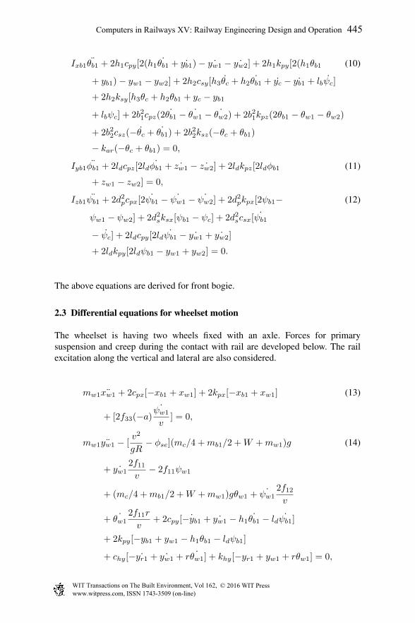
2.3 Differential equations for wheelset motion
The wheelset is having two wheels fixed with an axle. Forces for primarysuspension and creep during the contact with rail are developed below. The railexcitation along the vertical and lateral are also considered.
mw1 ¨xw1 + 2cpx[−xb1 + xw1] + 2kpx[−xb1 + xw1] (13)
+ [2f33(−a)˙ψw1
v] = 0,
mw1 ¨yw1 − [v2
gR− φse](mc/4 +mb1/2 +W +mw1)g (14)
+ ˙yw12f11v
− 2f11ψw1
+ (mc/4 +mb1/2 +W +mw1)gθw1 + ˙ψw12f12v
+ ˙θw12f11r
v+ 2cpy[ ˙−yb1 + ˙yw1 − h1 ˙θb1 − ld ˙ψb1]
+ 2kpy[−yb1 + yw1 − h1θb1 − ldψb1]
+ chy[− ˙yr1 + ˙yw1 + r ˙θw1] + khy[−yr1 + yw1 + rθw1] = 0,
Computers in Railways XV: Railway Engineering Design and Operation 445
www.witpress.com, ISSN 1743-3509 (on-line) WIT Transactions on The Built Environment, Vol 162, © 2016 WIT Press

mw1 ¨zw1 + [1 +v2
gRφse](mc/4 +mb1/2 +W +mw1)g (15)
+ λ2 ˙θw1ψw1yw12f11v
+ ˙yw12f11vθw1 + θw1
˙ψw12f12v
− λ22f12r
+ ψw1˙θw1
2f11r
v
+ 2cpy[ ˙−yb1 + ˙yw1 − h1 ˙θb1
− ld ˙ψb1] + chy[− ˙yr1 + ˙yw1 + r ˙θw1] + khy[−yr1 + yw1 + rθw1] = 0,
Ixw1¨θw1 + 2b21cpz[− ˙θb1 + ˙θw1] (16)
+ 2b21kpz[−θb1 + θw1] + achz[2a ˙θw1
+ ˙zr1 − ˙zr2] + akhz[2aθw1 + zr1 − zr2] + λra2f11v
˙θw1 + r22f11v
˙θw1
+ r ˙yw12f11v
+ aλ ˙yw12f11v
+ r ˙ψw12f12v
− v
rIyw1
˙ψw1
+ λa ˙ψw12f12v
− 2λ2f12θw1 + aλ(mc1/4 +mb1/2 +mw1 +W )gθw1
− λ4(mc1/4 +mb1/2 +mw1 +W )gyw12f12r
− λ2ψw12f22v
− 2ψw1f11r − ψw12f11aλ = 0,
Izw1¨ψw1 + 2d2pcpx[
˙ψw1 − ˙ψb1] + 2d2pkpx[ψw1 − ψb1] + 2f12ψw1 (17)
− ˙yw12f12v
+2f22 ˙ψw1
v+ a2 ˙θw1
2f33v
+ ˙θw12f33v
− r ˙θw12f12v
+ ˙θw1Iyw1v
r
+ 2f12ψw1 + (mc/4 +mb1/2 +W +mw1)aλgψw1 − aλyw12f33r
= 0.
The above equations are derived for front wheelset.
2.4 Coupling of locomotive WAP5, generator van, second class chair carand executive chair car
Combining the locomotive WAP5, generator van, second class chair and executivechair car with the help of couplers to make a train as shown in Figure 2.Longitudinal connection is considered in the mathematical modeling of the train.mc1, mc2, mc3, mc4 are masses, c1, c2, c3, k1, k2 and k3 are coupler lineardamping and linear spring coefficients of locomotive WAP5, generator van, secondclass chair and executive chair car respectively. The equations for coupling thetrain are derived below:
446 Computers in Railways XV: Railway Engineering Design and Operation
www.witpress.com, ISSN 1743-3509 (on-line) WIT Transactions on The Built Environment, Vol 162, © 2016 WIT Press
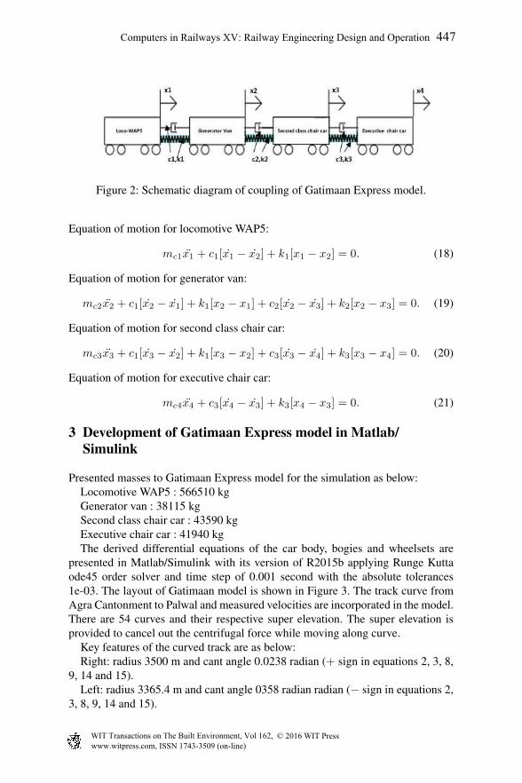
Figure 2: Schematic diagram of coupling of Gatimaan Express model.
Equation of motion for locomotive WAP5:
mc1x1 + c1[x1 − x2] + k1[x1 − x2] = 0. (18)
Equation of motion for generator van:
mc2x2 + c1[x2 − x1] + k1[x2 − x1] + c2[x2 − x3] + k2[x2 − x3] = 0. (19)
Equation of motion for second class chair car:
mc3x3 + c1[x3 − x2] + k1[x3 − x2] + c3[x3 − x4] + k3[x3 − x4] = 0. (20)
Equation of motion for executive chair car:
mc4x4 + c3[x4 − x3] + k3[x4 − x3] = 0. (21)
3 Development of Gatimaan Express model in Matlab/Simulink
Presented masses to Gatimaan Express model for the simulation as below:Locomotive WAP5 : 566510 kgGenerator van : 38115 kgSecond class chair car : 43590 kgExecutive chair car : 41940 kgThe derived differential equations of the car body, bogies and wheelsets are
presented in Matlab/Simulink with its version of R2015b applying Runge Kuttaode45 order solver and time step of 0.001 second with the absolute tolerances1e-03. The layout of Gatimaan model is shown in Figure 3. The track curve fromAgra Cantonment to Palwal and measured velocities are incorporated in the model.There are 54 curves and their respective super elevation. The super elevation isprovided to cancel out the centrifugal force while moving along curve.
Key features of the curved track are as below:Right: radius 3500 m and cant angle 0.0238 radian (+ sign in equations 2, 3, 8,
9, 14 and 15).Left: radius 3365.4 m and cant angle 0358 radian radian (− sign in equations 2,
3, 8, 9, 14 and 15).
Computers in Railways XV: Railway Engineering Design and Operation 447
www.witpress.com, ISSN 1743-3509 (on-line) WIT Transactions on The Built Environment, Vol 162, © 2016 WIT Press

Figure 3: The layout of Simulink model of a complete model of Gatimaan Express.
(a) Vertical track irregularity
(b) Lateral track irregularity
Figure 4: Track irregularity.
The simulation is done for a set of tracks which is having straight track, rightcurve track, again straight track and finally left curve track.
The measured sample data of lateral and vertical accelerations of locomotiveWAP 5, generator van, second class chair car and executive chair car of GatimaanExpress during the travel from New Delhi to Agra Cantonment was recorded for
448 Computers in Railways XV: Railway Engineering Design and Operation
www.witpress.com, ISSN 1743-3509 (on-line) WIT Transactions on The Built Environment, Vol 162, © 2016 WIT Press

(a) Lateral accelerations of Second Class ChairCar
(b) Vertical accelerations of Second Class ChairCar
Figure 5: Lateral and vertical accelerations of Second Class Chair for 20 secondsof simulation.
(a) Lateral accelerations of Loco WAP5 (b) Lateral accelerations of Generator Van
Figure 6: Lateral accelerations.
Computers in Railways XV: Railway Engineering Design and Operation 449
www.witpress.com, ISSN 1743-3509 (on-line) WIT Transactions on The Built Environment, Vol 162, © 2016 WIT Press

(a) Lateral accelerations of Second Class Chair Car (b) Lateral accelerations of Executive Chair Car
Figure 7: Lateral accelerations contd.
Table 1: Lateral accelerations.
Lateral acceleration Confidence (%)
Loco WAP5 94.07
Generator Van 88.79
Second Class Chair Car 83.69
Executive Chair Car 90.44
Table 2: Vertical accelerations.
Vertical acceleration Confidence (%)
Loco WAP5 87.33
Generator Van 91.07
Second Class Chair Car 78.86
Executive Chair Car 87.14
17 km. These accelerations with speed of Gatimaan Express was recorded in realtime by using LabView of National Instruments at sampling rate 100 samples persecond.
The response of these irregularities are shown in Figures 4(a) and 4(b). Thesimulation is run for 20 seconds but the performances of Gatimaan Express modelare shown for 2 seconds in subsequent figures for clarity. Compared simulatedresults with measured data of lateral and vertical accelerations of second classchair car for 20 seconds run of simulation are shown in Figures 5(a) and 5(b).
The simulated results of the lateral and vertical accelerations of locomotiveWAP5, generator van, second class chair car and executive chair car are comparedwith respective measured acceleration sample data and are shown in Figures 6(a),6(b), 7(a), 7(b), 8(a), 8(b), 9(a), 9(b) respectively.
The simulated accelerations are estimated through the Hammerstein-Wienermodel to get best curve fit with their respective measured accelerations. It is shownthat there is good match between the simulated results and measured sample data.The confidence level percentage in curve fitting of lateral and vertical accelerationsof model are shown in Tables 1 and 2.
450 Computers in Railways XV: Railway Engineering Design and Operation
www.witpress.com, ISSN 1743-3509 (on-line) WIT Transactions on The Built Environment, Vol 162, © 2016 WIT Press

(a) Vertical accelerations of Loco WAP5 (b) Vertical accelerations of Generator Van
Figure 8: Vertical accelerations.
(a) Vertical accelerations of Second Class Chair Car (b) Vertical accelerations of Executive Chair Car
Figure 9: Vertical accelerations contd.
The roll motions, pitch motions and yaw motions of WAP5, generator van,second class chair car and executive chair car are shown in Figures 10, 11, 12respectively. A harmonic oscillations can be seen in their performances.
The simulated longitudinal, lateral and vertical suspension fores of WAP5,generator van, second class chair car and executive chair car are express inFigures 13, 14, 15. The longitudinal suspension forces of the model are less thanthe lateral and vertical suspension forces.
Because of the vehicle speed, track geometry and track irregularities, there arevariations in the three dimensional forces. These variations should be under certainlimit otherwise, the train can be derailed as it crosses the limit. The major inputparameter values are incorporated to the model are listed in Table 3.
Computers in Railways XV: Railway Engineering Design and Operation 451
www.witpress.com, ISSN 1743-3509 (on-line) WIT Transactions on The Built Environment, Vol 162, © 2016 WIT Press

Figure 10: Roll motion.
Figure 11: Pitch motion.
3.1 Conclusion and remarks
The dynamic model of Gatimaan Express, having locomotive WAP5, generatorvan, second class chair car and executive chair car is developed in Matlab/Simulinksuccessfully. The various masses of model are considered, keeping spring stiffnessand damping coefficients constants. The model is exposed to rail irregularitiesalong the lateral and vertical directions to excite vibration in it on the tangentialand curvilinear tracks. The simulated lateral and vertical accelerations of themodel are in good match with the measured sample data. The sharp peaks in bothlateral and vertical dynamics are observed which are due to track geometry, trackirregularities.
452 Computers in Railways XV: Railway Engineering Design and Operation
www.witpress.com, ISSN 1743-3509 (on-line) WIT Transactions on The Built Environment, Vol 162, © 2016 WIT Press

Figure 12: Yaw motion.
Figure 13: Longitudinal suspension force.
The lateral, roll and yaw motions of rail vehicle are more responsible for huntingthan the vertical and pitch dynamics.
The model can also be studied for lateral stability and hunting behavior. Furtherthe derailment dynamics can be analyzed as there is suspension damage. It canaffect the ratio of lateral and vertical force and finally cause for the derailment.
Computers in Railways XV: Railway Engineering Design and Operation 453
www.witpress.com, ISSN 1743-3509 (on-line) WIT Transactions on The Built Environment, Vol 162, © 2016 WIT Press

Figure 14: Lateral suspension force.
Figure 15: Vertical suspension force.
4 Future work
The model can be made more robust by adding the impact of the vertical andlateral dynamics of neighbor coaches. The hunting and critical performances ofcar body and wheelset will be analyzed. The extensive work of train dynamicsincluding coupling of train with different spring stiffness and damping coefficientsfor locomotive WAP5, generator van, second class chair car and executive chaircar and derailment dynamics can be performed.
454 Computers in Railways XV: Railway Engineering Design and Operation
www.witpress.com, ISSN 1743-3509 (on-line) WIT Transactions on The Built Environment, Vol 162, © 2016 WIT Press
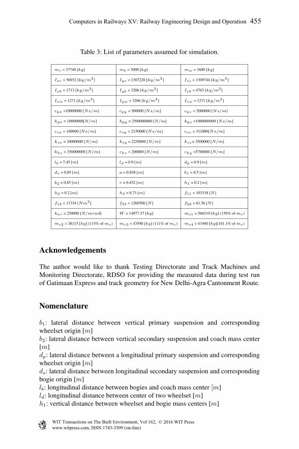
Table 3: List of parameters assumed for simulation.
mc = 37740 [kg] mb = 3000 [kg] mw = 1600 [kg]
Ixc = 56932 [kg/m2] Iyc = 1307220 [kg/m2] Izc = 1309744 [kg/m2]
Ixb = 1713 [kg/m2] Iyb = 3206 [kg/m2] Izb = 4763 [kg/m2]
Ixw = 1271 [kg/m2] Iyw = 3206 [kg/m2] Izw = 1271 [kg/m2]
cpx =10000000 [Ns/m] cpy = 500000 [Ns/m] cpz = 2000000 [Ns/m]
kpx = 10000000[N/m] kpy = 2500000000 [N/m] kpz =1000000000 [Ns/m]
csx = 100000 [Ns/m] csy = 2150000 [Ns/m] csz = 311000[Ns/m]
ksx = 10000000 [N/m] ksy = 2250000 [N/m] ksz= 3500000 [N/m]
khz = 350000000 [N/m] chz = 200000 [N/m] chy =5700000 [N/m]
lb = 7.45 [m] ld = 0.9 [m] dp = 0.9 [m]
ds = 0.85 [m] a = 0.838 [m] b1 = 0.5 [m]
b2 = 0.85 [m] r = 0.452 [m] h1 = 0.2 [m]
h2 = 0.2 [m] h3 = 0.73 [m] f11 = 103318 [N ]
f12 = 11334 [Nm2] f33 = 1260500 [N ] f22 = 61.56 [N ]
kar = 250000 [N/mrad] W = 14977.57 [kg] mc1 = 566510 [kg] (150% of mc)
mc2 = 38115 [kg] (115% of mc) mc3 = 43590 [kg] (111% of mc) mc4 = 41940 [kg](101.1% of mc)
Acknowledgements
The author would like to thank Testing Directorate and Track Machines andMonitoring Directorate, RDSO for providing the measured data during test runof Gatimaan Express and track geometry for New Delhi-Agra Cantonment Route.
Nomenclature
b1: lateral distance between vertical primary suspension and correspondingwheelset origin [m]b2: lateral distance between vertical secondary suspension and coach mass center[m]dp: lateral distance between a longitudinal primary suspension and correspondingwheelset origin [m]ds: lateral distance between longitudinal secondary suspension and correspondingbogie origin [m]lb: longitudinal distance between bogies and coach mass center [m]ld: longitudinal distance between center of two wheelset [m]h1: vertical distance between wheelset and bogie mass centers [m]
Computers in Railways XV: Railway Engineering Design and Operation 455
www.witpress.com, ISSN 1743-3509 (on-line) WIT Transactions on The Built Environment, Vol 162, © 2016 WIT Press

h2: vertical distance between bogie mass center and lateral secondary suspen-sion [m]h3: vertical distance between lateral secondary suspension and car body mass cen-ter [m]csx, csy and csz: long., lateral and vertical Secondary damping coefficients[Ns/m]cpx, cpy and cpz: long., lateral and vertical Primary damping coefficients [N/m]kpx, kpy and kpz: long., lateral and vertical Primary spring coefficients [N/m]ksx, ksy and ksz: long., lateral and vertical Secondary spring coefficients [N/m]chz and chy: vertical and lateral hertz damping coefficient [N/m]khz and khy: vertical and lateral hertz spring coefficient [N/m]Ixb, Iyb and Izb: roll, pitch and yaw mass moment of inertia of bogie [kg/m2]Ixc, Iyc and Izc: roll, pitch and yaw mass moment of inertia of car body [kg/m2]Ixw, Iyw and Izw: roll, pitch and yaw mass moment of inertia of wheelset [kg/m2]mc, mb, and mw,: mass of car body, bogie and wheelset [kg]r and R: nominal wheel radius and radius of track [m]zr and yr: vertical and lateral track excitation [m]θc, θb,θw: roll displacement of car body, bogie and wheelset [rad]φc and φb: pitch displacement of car body and bogie [rad]ψc, ψb and ψw: yaw displacement of car body, bogie and wheelset [rad]λ: wheel profile conicity [rad]a: half of track gauge [m]f11: lateral creep coefficient [N ]f12: lateral/spin creep coefficient [Nm2]f33: spin creep coefficient [N ]f22: longitudinal creep coefficient [N ]kar: anti roll stiffness coefficient [N/mrad]
References
[1] Y. Q. Sun and M. Dhanasekar. A dynamics model for the vertical interactionof the rail track and wagon system. International Journal of Solids andStructures, 39(1):1337–1359, 2002.
[2] M. Bayraktar, F. Dikmen and R. Guclu. Dynamic analysis of rail vehicle axle.Indian Academy of Science, 38(2): 265–280, 2013.
[3] F. Y. Tsai and W. F. Wu. Stability analysis of railway vehicles and itsverifications through field test data. Journal of the Chinese Institute ofEngineers, 29(3): 493–505, 2006.
[4] E. Demir. 3D suspension characterization of a metro vehicle. In Proc. of theInt. Conf. on Advanced railway Engineering, pages 13–30, Istanbul, 2015.
[5] K. H. Ali Abood and R. A. Khan. Railway carriage to study the influence ofvertical secondary stiffness on ride comfort of railway car body running oncurved tracks. Journal of Modern Applied Science, 5(2): 11–24, 2011.
[6] J. Jung, P. Kim and J. Seok. A parametric dynamics study on hunting
456 Computers in Railways XV: Railway Engineering Design and Operation
www.witpress.com, ISSN 1743-3509 (on-line) WIT Transactions on The Built Environment, Vol 162, © 2016 WIT Press

stability of full duel-bogie railway vehicle. International Journal of PrecisionEngineering and Manufacturing, 12(3): 505–519, 2011.
[7] M. Ranjbar and M. R. Ghazavi. Lateral stability analysis of high speed railwayvehicle on curve. In Proc. of the Int. conf. of Advances robotics, measuredengineering, mechanical engineering and design, pages 11–14, 2012.
[8] S. Sezer and A. Erdem Ataly. Dynamic modeling and fuzzy logic control ofvibrations of a railway vehicle for different track irregularities. SimulationModelling Practice and Theory, 19(1): 1873–1894, 2011.
Computers in Railways XV: Railway Engineering Design and Operation 457
www.witpress.com, ISSN 1743-3509 (on-line) WIT Transactions on The Built Environment, Vol 162, © 2016 WIT Press