modeling and simulation of five-phase induction motor fed
TRANSCRIPT

6 Page 6-22 © MAT Journals 2019. All Rights Reserved
Journal of Advances in Electrical Devices
Volume 4 Issue 2
Modeling and Simulation of Five-Phase Induction Motor Fed With Pulse Width Modulated Five-Phase Multilevel Voltage
Source Inverter Topologies
Gerald .C. Diyoke1, Candidus.U. Eya2
1Department of Electrical and Electronic Engineering, Michael Okpara University of Agriculture Road 10, Federal Low Cost Umuahia,Umudike, Abia State Nigeria.
2Department of Electrical and Electronic Engineering, University of Nigeria Nsukka No 4 Umudikwu Village, Off-Orba Road, Nsukka, Enugu State, Nigeria
Email: [email protected]
Abstract
This paper presents modelling and simulation of five-phase induction motor fed with pulse width modulated five-phase multilevel voltage source inverter. The conventional and diode clamped multilevel five-phase inverter configurations are reviewed with pulse width modulation (PWM) techniques. A hybrid three-level inverter topology with less number of components count is proposed for five-phase induction motor drive. The dynamic analysis of five-phase voltage equations in d-q axis of the induction motor are stated and modelled using Matlab/Simulink/Simscape blocks. The simulation results based on conventional and three-level five-phase inverters are displayed while the hybrid inverter topology showed some better performance based on the following: : at 0.0127secs maximum torque of 34.54Nm occurred, maximum stator current occurred for 0.18secs with a value of 10A, 9.99% total harmonic distortion was obtained and 15KW power rating was obtained. Keywords: Five-phase induction motor, multilevel, sinusoidal pulse width modulation, voltage source inverter
INTRODUCTION Multiphase (more than three phase) machines are alternating current (AC) machines that are known for a stator winding [1-6]. They consist of generic number of phases. Recently, electric machines driven by multiphase inverter technology have many advantages over the conventional three phase machine and inverters. For instance, in decreasing the amplitude and increasing the frequency of torque pulsation, higher torque density, reducing the rotor harmonic current distortion per phase without increasing the voltage per phase, lowering the dc-link current harmonics, better noise characteristics, higher reliability and high fault tolerance [7-9]. Three phase induction motors have wide range of applications, thus, they are invariably used in many residential, commercial, industrial and utility applications due to their low cost, reliable operation, robust operation and low maintenance. Multiphase motor
drives with increased phase number lead to an improvement in medium to high power drives application. The multiphase induction motor finds application in a particular and vital area where high reliability is needed, for instance; Electric vehicle/Hybrid Electric vehicles, aerospace application, ship propulsion and locomotive traction, battery powered electric vehicles and high power application [10 – 12]. The performance analysis of five-phase and three phase induction motor was proposed [13]. The performance analyses are carried out using conventional five and three phase inverter topologies. The author observed that the five-phase induction motor has a good performance over the three-phase induction motor. A comparative study between three phase and five phase induction motor by using a converter topology are described in [14]. The author worked on the challenges of fault occurring on both phases. It is noticed that

7 Page 6-22 © MAT Journals 2019. All Rights Reserved
Journal of Advances in Electrical Devices
Volume 4 Issue 2
the five phase converter tolerates fault to a greater extent than the conventional three phase. A step by step approach of a dynamic modeling of five phase induction motor was carried out by authors in [15]. Also, an output total harmonic distortion (THD) of the five phase inverter configurations and agreeing dynamic performance of five phase induction motor are researched by [16]. The author successfully implemented the proposed inverter topology with induction motor load. The modeling and simulation of five phase inverter fed induction motor drive and three phase inverter fed induction motor drive was presented in [17]. The output of the five-leg inverter and three leg inverters is controlled by SPWM control technique method using Matlab/Simulink software. The author concluded that the ripple content of various parameters (current, torque and speed) can be smoothened by supplying the motor with five phase supply than three phase supply. Also Sequential Five Leg Inverter for Five Phase Supply is presented in [18]. The authors used space vector modulation strategy though time consuming and complex calculation involvement for the analysis and performance evaluation. THD with less harmonic content was obtained.This paper presents the Modeling and Simulation of Five Phase Induction Motor Fed with Five Phase Hybrid Multilevel Voltage Source Inverter Topologies. The structure of this paper is
organized as follows. Section-II deals with the five-phase conventional inverter topology with sinusoidal pulse width modulation (SPWM) techniques. Also, switching sequence of five phase inverter presented. Section-III gives the five-phase diode clamped and hybrid inverter configurations with their mode of operations. Section-IV depicts the mathematical modeling of five phase induction motor which includes the q-d-0 axis equivalent circuit of five phase induction motor in arbitrary reference frame. Section-V presented mathematical model implementation using MATLAB/Simulink. In section VI, MATLAB/Simulink simulation results are presented and discussed. Finally, Section-VII presents the conclusion part. CONVENTIONAL FIVE PHASE INVERTER TOPOLOGY The basic power circuit topology of conventional five phase voltage source inverter is shown in Fig. 1. Insulated gate bipolar transistor (IGBT) is used as the power switches. The anti-parallel diodes provide reverse current path such that when a particular IGBT is ON, one output terminal and one input terminal will be connected. In multiphase inverter n number of phases can be generated, as each leg of the inverter represents a phase, thus by increasing the number of legs in the inverter, the number of phases can equally be increased.
n
g
aZbZ
avbv cv
dv ev
cZdZ
eZ
dcV
1S3S 5S
7S 9S
6S8S
10S 2S 4S
1D
6D
3D
8D
5D
10D
7D9D
2D4D
Figure 1: Five phase conventional inverter topology.
Ten-Step Inverter In five phases conventional ten step
8 Page 6-22 © MAT Journals 2019. All Rights Reserved
Journal of Advances in Electrical Devices
Volume 4 Issue 2
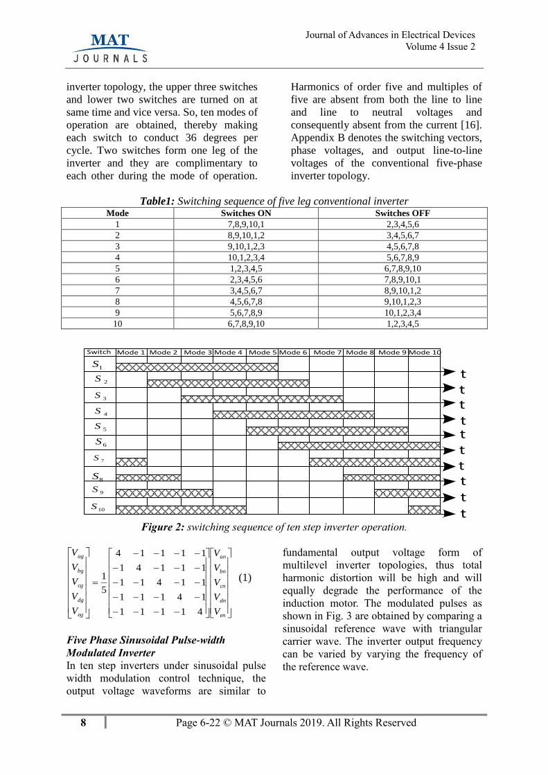
inverter topology, the upper three switches
and lower two switches are turned on at
same time and vice versa. So, ten modes of
operation are obtained, thereby making
each switch to conduct 36 degrees per
cycle. Two switches form one leg of the
inverter and they are complimentary to
each other during the mode of operation.
Harmonics of order five and multiples of
five are absent from both the line to line
and line to neutral voltages and
consequently absent from the current [16].
Appendix B denotes the switching vectors,
phase voltages, and output line-to-line
voltages of the conventional five-phase
inverter topology.
Table1: Switching sequence of five leg conventional inverter Mode Switches ON Switches OFF
1 7,8,9,10,1 2,3,4,5,6
2 8,9,10,1,2 3,4,5,6,7
3 9,10,1,2,3 4,5,6,7,8
4 10,1,2,3,4 5,6,7,8,9
5 1,2,3,4,5 6,7,8,9,10
6 2,3,4,5,6 7,8,9,10,1
7 3,4,5,6,7 8,9,10,1,2
8 4,5,6,7,8 9,10,1,2,3
9 5,6,7,8,9 10,1,2,3,4
10 6,7,8,9,10 1,2,3,4,5
Mode 1Switch Mode 2
1S
Mode 3 Mode 4 Mode 5 Mode 6 Mode 7 Mode 8 Mode 9 Mode 10
2S
tt
t3S
4S
5S
6S
7S
8S
9S
10S
ttttttt
Figure 2: switching sequence of ten step inverter operation.
−−−−
−−−−
−−−−
−−−−
−−−−
=
en
dn
cn
bn
an
eg
dg
cg
bg
ag
V
V
V
V
V
V
V
V
V
V
41111
14111
11411
11141
11114
5
1 (1)
Five Phase Sinusoidal Pulse-width
Modulated Inverter
In ten step inverters under sinusoidal pulse
width modulation control technique, the
output voltage waveforms are similar to
fundamental output voltage form of
multilevel inverter topologies, thus total
harmonic distortion will be high and will
equally degrade the performance of the
induction motor. The modulated pulses as
shown in Fig. 3 are obtained by comparing a
sinusoidal reference wave with triangular
carrier wave. The inverter output frequency
can be varied by varying the frequency of
the reference wave.

9 Page 6-22 © MAT Journals 2019. All Rights Reserved
Journal of Advances in Electrical Devices
Volume 4 Issue 2
Figure 3: switching signals for SPWM inverter
MULTILEVEL FIVE PHASE
INVERTER TOPOLOGIES
Three-phase multilevel inverter topologies
of diode clamped and hybrid are extended
to five phase. Fig. 4 shows the inverter
power circuit for three-level five-phase
diode clamped configuration. While Fig. 6
shows the hybrid inverter power circuit
with less number of circuit components for
three-level five-phase topology.
Three Level Diode Clamped Inverter
Configuration
This circuit topology consists of two
battery sources connected in series whose
junction serves as a neutral point. The
three-level output voltage is generated as
dcV ,2
dcV,0. Each leg or pole voltage
consists of four power switches. In order
to improve on output voltage performance,
the number of power switches and series
battery have to be increased.
Consequently, increasing the circuit
performance increases its cost, switching
losses, weight and complexity of the
circuit configuration. The firing signals are
generated by comparing the carrier and
reference signals as shown in Fig. 5.
g
aZbZ cZ dZ
eZ
n
1aS1bS 1cS 1dS
1eS
2aS
1aS
2aS
2bS
1bS
2bS
2cS
1cS
2cS 2dS 2eS
1dS 1eS
2dS 2eS
2
dcV
2
dcV
av bv cv dvev
Figure 4: Three level five phase diode clamped inverter configuration.
0 0.002 0.004 0.006 0.008 0.01 0.012 0.014 0.016 0.018 0.02
0
2
4
6
8
10
12
14
16
18
20
Time [s]
Am
pli
tud
e [
v]
S1
S3
S5
S7
S9
S6
S8
S10
S2
S4

10 Page 6-22 © MAT Journals 2019. All Rights Reserved
Journal of Advances in Electrical Devices
Volume 4 Issue 2
Figure 5: switching signals for three-level five-phase diode clamped inverter configuration.
Three-Level Hybrid Inverter
Configuration
This circuit topology consists of two
battery sources connected in series whose
junction serves as a neutral point and a
bidirectional switch is connected at this
point. The three-level output voltage is
generated as: dcV ,2
dcV, 0. Each leg or pole
voltage consists of two power switches
and one bidirectional switch which
consists of four diodes and one power
switch as shown in Fig. 6. In order to
improve on output voltage performance,
the number of power switches and series
battery have to be increased.
Consequently, increasing the circuit
performance increases its cost, switching
losses, weight and complexity of the
circuit configuration. Fig. 7 shows all the
power switches control signals for the five
poles or legs.
1S
6S
aSav
1D
6D
1aD
1aD
2aD
2aD
3S
8S
bSbv
3D
8D
1bD
1bD
2bD
2bD
5S
10S
cScv
5D
10D
1cD
1cD
2cD
2cD
7S
2S
dSdv
7D
2D
1dD
1dD
2dD
2dD
9S
4S
eS ev
9D
4D
1eD
1eD
2eD
2eD
g
aZ bZ cZdZ eZ
n
2
dcV
2
dcV
Figure 6: Three level five phase hybrid inverter configuration.
0 0.002 0.004 0.006 0.008 0.01 0.012 0.014 0.016 0.018 0.02-7
-6
-5
-4
-3
-2
-1
0
1
2
Time [s]
Am
pli
tud
e [
v]
Va
Vb
Vc
Vd
Ve
Vcr1
Vcr2
Vcr3
Vcr4
Sa1
Sa2
NotSa1
NotSa2

11 Page 6-22 © MAT Journals 2019. All Rights Reserved
Journal of Advances in Electrical Devices
Volume 4 Issue 2
Figure 7: switching signal for hybrid inverter topology
DYNAMIC MODELING OF FIVE
PHASE INDUCTION MOTOR
The mathematical model of five-phase
induction motor given in equations (2) to
(9) is used to simulate the five-phase
induction machine as reported in [19-20].
The machine’s voltage equations in the
common reference frame:
+=
+=
+=
++=
+−=
ssss
ysyssys
xsxssxs
qsdsaqssqs
dsqsadssds
piRV
piRV
piRV
piRV
piRV
000
(2)
+=
+=
+=
+−+=
+−−=
rrrr
yryrryr
xrxrrxr
qrdraqrrqr
drqradrrdr
piRV
piRV
piRV
piRV
piRV
000
)(
)(
(3)
Where
=
=
=
++=
++=
slss
yslsys
xslsxs
qrmqsmlsqs
drmdsmlsds
iL
iL
iL
iLiLL
iLiLL
00
)(
)(
(4)
=
=
=
++=
++=
rlrr
yrlryr
xrlrxr
qsmqrmlrqr
dsmdrmlrdr
iL
iL
iL
iLiLL
iLiLL
00
)(
)(
(5)
Torque equation can be expressed by
−=
−=
][
)(2
5
qrdsqsdrme
qrdsqsdre
iiiiPLT
iiiiMP
T (6)
dt
d
P
JTT r
Le
=− (7)
The line-to-neutral voltages can be transformed to the d-q planes using the following
transformation matrix as shown below
0 0.002 0.004 0.006 0.008 0.01 0.012 0.014 0.016 0.018 0.020
5
10
15
20
25
30
Time [s]
Am
pli
tud
e [
v]
S1
Sa
S6
S3
Sb
S8
S5
Sc
S10
S7
Sd
S2
S9
Se
S4

12 Page 6-22 © MAT Journals 2019. All Rights Reserved
Journal of Advances in Electrical Devices
Volume 4 Issue 2
−
+
−
+
−
+
−
+
+
+
−
−
+
+
−
−
=
2
1
2
1
2
1
2
1
2
15
4sin
5
2sin
5
2sin
5
4sinsin
5
4cos
5
2cos
5
2cos
5
4coscos
5
4sin
5
2sin
5
4sin
5
2sinsin
5
4cos
5
2cos
5
4cos
5
2coscos
5
2
K
(8)
The stator currents can be expressed as
=
s
ys
xs
qs
ds
es
ds
cs
bs
as
i
i
i
i
i
i
i
i
i
i
0
15
16sin
5
16cos
5
8sin
5
8cos
15
12sin
5
12cos
5
6sin
5
6cos
15
8sin
5
8cos
5
4sin
5
4cos
15
4sin
5
4cos
5
2sin
5
2cos
10101
5
2
(9)
MATLAB/SIMULINK
IMPLEMENTATION
The inverter voltage, flux, torque
equations and transformation matrices
are used to implement the model of five
phase multilevel inverter fed induction
motor in MATLAB/Simulink as shown
in appendix and general block diagram
depicted Fig. 8. The input to the motor
is generated from five phase multilevel
SPWM inverter supply. The five phases
to two phase conversion blockstransfers
the five phase stator voltages to d-q axis
voltages.
DC Input
Voltage
Five-phase
Multilevel
Inverter
Figs. (1 or 4 or 6)
Eqns. (2, 3,
4 and 5)Eqns. (6 and 7) Display
Load
TL
Figs. (3 or 5 or 7)Reference signal
Carrier signalComparator
Figure 8: The general block diagram of the five-phase inverter fed induction motor.
SIMULATION RESULTS AND
DISCUSSIONS
The mathematical model given in the
paper is implemented in
MATLAB/Simulink/Simpower system
block sets. The inbuilt IGBT/Diode blocks
are used to simulate the inverter power
circuit. The three different inverter
13 Page 6-22 © MAT Journals 2019. All Rights Reserved
Journal of Advances in Electrical Devices
Volume 4 Issue 2
topologies are analyzed through their
output voltages, stator currents, motor
speed, electro-magnetic torque, speed-
electromagnetic and total harmonic
distortions. The input voltage for the
inverter is 440 volts dc supply. The
simulations are carried out under
modulation index of 1 and frequency index
of 40 at 50Hz operating frequency. The
five-phase induction motor is loaded with
10N-m and the performance of each
topology is as discussed as follow.
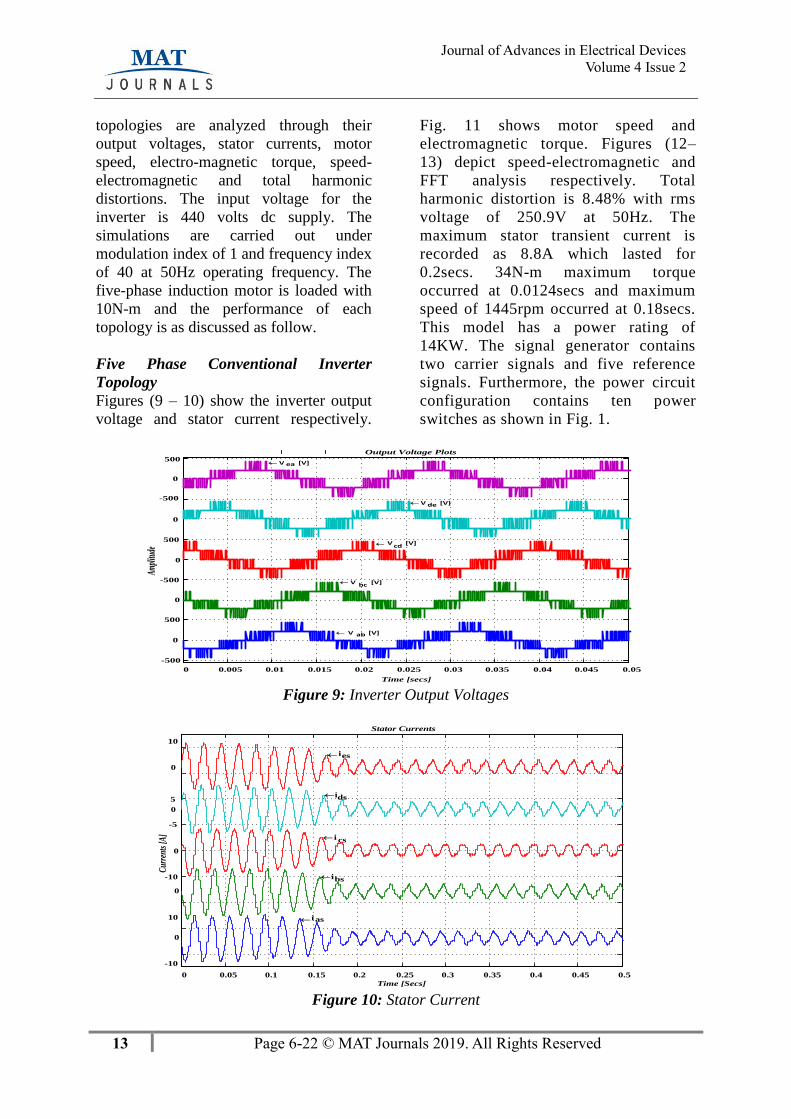
Five Phase Conventional Inverter
Topology
Figures (9 – 10) show the inverter output
voltage and stator current respectively.
Fig. 11 shows motor speed and
electromagnetic torque. Figures (12–
13) depict speed-electromagnetic and
FFT analysis respectively. Total
harmonic distortion is 8.48% with rms
voltage of 250.9V at 50Hz. The
maximum stator transient current is
recorded as 8.8A which lasted for
0.2secs. 34N-m maximum torque
occurred at 0.0124secs and maximum
speed of 1445rpm occurred at 0.18secs.
This model has a power rating of
14KW. The signal generator contains
two carrier signals and five reference
signals. Furthermore, the power circuit
configuration contains ten power
switches as shown in Fig. 1.
0 0.005 0.01 0.015 0.02 0.025 0.03 0.035 0.04 0.045 0.05
-500
0
500
500
Time [secs]
Am
plitu
de
Output Voltage Plots
V ea [V]
V de [V]
Vcd
[V]
V bc [V]
V ab [V]
0
-500
500
0
0
0
-500
Figure 9: Inverter Output Voltages
0 0.05 0.1 0.15 0.2 0.25 0.3 0.35 0.4 0.45 0.5
-10
-10
0
-5
5
0
10
Stator Currents
Cur
rent
s [A
]
Time [Secs]
ies
ids
i cs
ibs
ias
0
0
10
0
Figure 10: Stator Current

14 Page 6-22 © MAT Journals 2019. All Rights Reserved
Journal of Advances in Electrical Devices
Volume 4 Issue 2
0 0.05 0.1 0.15 0.2 0.25 0.3 0.35 0.4 0.45 0.50
500
1000
1500
Speed Plot
Wr
[RP
M]
(A) Time [secs]
0 0.05 0.1 0.15 0.2 0.25 0.3 0.35 0.4 0.45 0.5
0
10
20
30
Electromagnetic Torque Plot
Te
[N-m
]
(B) Time [secs] Figure 11: (A) Speed curve, (B) Torque curve
0 200 400 600 800 1000 1200 1400 1600
-5
0
5
10
15
20
25
30
35
Electromagnetic Torque Versus Speed Plot
Te [
N-m
]
Speed [RPM] Figure 12: Electromagnetic curve.
0 5 10 15 200
50
100
150
200
250
Harmonic order
Fundamental (50Hz) = 250.9 , THD= 8.48%
Mag
2 4 6 8 10 12 14 16 18 200
2
4
6
8
10
12
Figure 13: FFT analysis of conventional Inverter.
15 Page 6-22 © MAT Journals 2019. All Rights Reserved
Journal of Advances in Electrical Devices
Volume 4 Issue 2
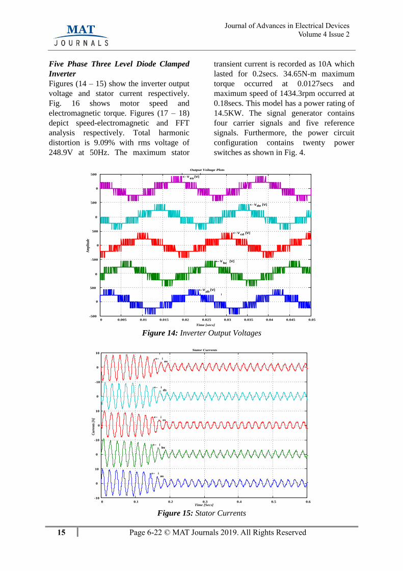
Five Phase Three Level Diode Clamped
Inverter
Figures (14 – 15) show the inverter output
voltage and stator current respectively.
Fig. 16 shows motor speed and
electromagnetic torque. Figures (17 – 18)
depict speed-electromagnetic and FFT
analysis respectively. Total harmonic
distortion is 9.09% with rms voltage of
248.9V at 50Hz. The maximum stator
transient current is recorded as 10A which
lasted for 0.2secs. 34.65N-m maximum
torque occurred at 0.0127secs and
maximum speed of 1434.3rpm occurred at
0.18secs. This model has a power rating of
14.5KW. The signal generator contains
four carrier signals and five reference
signals. Furthermore, the power circuit
configuration contains twenty power
switches as shown in Fig. 4.
0 0.005 0.01 0.015 0.02 0.025 0.03 0.035 0.04 0.045 0.05-500
500
-500
0
500
500
500
Time [secs]
Am
plitu
de
Output Voltage Plots
V ea [V]
Vde [V]
V cd [V]
Vbc
[V]
Vab
[V]
0
0
0
0
Figure 14: Inverter Output Voltages
0 0.1 0.2 0.3 0.4 0.5 0.6-10
0
10
0
-10
0
10
0
-10
0
10 Stator Currents
Cu
rren
ts [
A]
Time [Secs]
ies
ids
ics
ibs
ias
Figure 15: Stator Currents

16 Page 6-22 © MAT Journals 2019. All Rights Reserved
Journal of Advances in Electrical Devices
Volume 4 Issue 2
0 0.05 0.1 0.15 0.2 0.25 0.3 0.35 0.4 0.45 0.50
500
1000
1500
Speed Plot
Wr [
RPM
]
(A) Time [secs]
0 0.05 0.1 0.15 0.2 0.25 0.3 0.35 0.4 0.45 0.5
0
10
20
30
Electromagnetic Torque Plot
Te
[N-m
]
(B) Time [secs] Figure 16: (A) Speed curve, (B) Torque curve
0 200 400 600 800 1000 1200 1400 1600
-5
0
5
10
15
20
25
30
35
Electromagnetic Torque Versus Speed Plot
Te
[N-m
]
Speed [RPM] Figure 17: Electromagnetic Curve
0 5 10 15 200
20
40
60
80
100
Harmonic order
Fundamental (50Hz) = 248.9 , THD= 9.09%
Ma
g (
% o
f F
un
da
men
tal)
2 4 6 8 10 12 14 16 18 200
1
2
3
4
5
6
Figure 18: FFT analysis
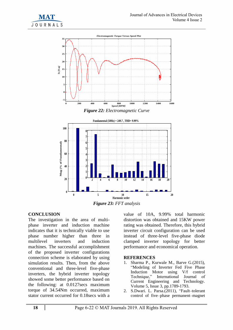
Five Phase Three Level Hybrid Inverter
Configuration
Figures (19 – 20) show the inverter output
voltage and stator current respectively.
Fig. 21 shows motor speed and
electromagnetic torque. Figures (22 – 23)
depict speed-electromagnetic and FFT
analysis respectively. Total harmonic
distortion is 9.99% with rms voltage of
249.7V at 50Hz. The maximum stator

17 Page 6-22 © MAT Journals 2019. All Rights Reserved
Journal of Advances in Electrical Devices
Volume 4 Issue 2
transient current is recorded as 10A which
lasted for 0.2secs. 34.54N-m maximum
torque occurred at 0.0127secs and
maximum speed of 1440rpm occurred at
0.18secs. This model has a power rating of
15kW. The signal generator contains four
carrier signals and five reference signals.
Furthermore, the power circuit
configuration contains fifteen power
switches as shown in Figure 6.
0 0.005 0.01 0.015 0.02 0.025 0.03 0.035 0.04 0.045 0.05-500
0
500
0
-500
0
500
0
500
0
500
Time [secs]
Output Voltage Plots
Vea
[V]
Vde
[V]
Vcd [V]
V bc [V]
Vab
[V]
Figure 19: Inverter Output Voltage
0 0.1 0.2 0.3 0.4 0.5 0.6-10
0
10
0
-10
0
10
0
-10
0
10 Stator Currents
Cur
rent
s [A
]
Time [Secs]
ies
ids
ics
ibs
ias
Figure 20: Stator Currents
0 0.05 0.1 0.15 0.2 0.25 0.3 0.35 0.4 0.45 0.50
500
1000
1500
Speed Plot
Wr
[RPM
]
(A) Time [secs]
0 0.05 0.1 0.15 0.2 0.25 0.3 0.35 0.4 0.45 0.5
0
10
20
30
Electromagnetic Torque Plot
Te
[N-m
]
(B) Time [secs] Figure 21: (A) Speed curve, (B) Torque curve
18 Page 6-22 © MAT Journals 2019. All Rights Reserved
Journal of Advances in Electrical Devices
Volume 4 Issue 2
0 200 400 600 800 1000 1200 1400 1600
-5
0
5
10
15
20
25
30
35
Electromagnetic Torque Versus Speed Plot
Te
[N-m
]
Speed [RPM] Figure 22: Electromagnetic Curve
0 5 10 15 200
20
40
60
80
100
Harmonic order
Ma
g (
% o
f F
un
da
men
tal)
Fundamental (50Hz) = 249.7 , THD= 9.99%
2 4 6 8 10 12 14 16 18 200
1
2
3
4
5
6
7
8
Figure 23: FFT analysis
CONCLUSION
The investigation in the area of multi-
phase inverter and induction machine
indicates that it is technically viable to use
phase number higher than three in
multilevel inverters and induction
machines. The successful accomplishment
of the proposed inverter configurations
connection scheme is elaborated by using
simulation results. Then, from the above
conventional and three-level five-phase
inverters, the hybrid inverter topology
showed some better performance based on
the following: at 0.0127secs maximum
torque of 34.54Nm occurred, maximum
stator current occurred for 0.18secs with a
value of 10A, 9.99% total harmonic
distortion was obtained and 15KW power
rating was obtained. Therefore, this hybrid
inverter circuit configuration can be used
instead of three-level five-phase diode
clamped inverter topology for better
performance and economical operation.
REFERENCES 1. Sharma P., Kurwale M., Barve G.(2015),
“Modeling of Inverter Fed Five Phase Induction Motor using V/f control Technique,” International Journal of Current Engineering and Technology. Volume 5, Issue 3, pp.1789-1793.
2. S.Dwari. L. Parsa.(2011), “Fault–tolerant control of five–phase permanent–magnet

19 Page 6-22 © MAT Journals 2019. All Rights Reserved
Journal of Advances in Electrical Devices
Volume 4 Issue 2
motors with trapezoidal back EMF ,” IEEE Transactions on Industrial Electronics, volume 58, no. 2, 2011, pp. 476–485.
3. F. Locment, E. Semail, X. Kestelyn.(2008), “Vectorial Approach–Based Control of a Seven–Phase Axial Flux Machine Designed for Fault Operation,” IEEE Transactions on Industrial Electronics, volume. 55, Issue. 10, pp. 3682–3691.
4. J.R. Fu, T.A. Lipo.(1994), “Disturbance free operation of a multiphase current regulated motor drive with an opened phase,” IEEE Transactions on Industry Applications, vol. 30, Issue 5, pp. 1267–1274.
5. A. Tani, M. Mengoni, L. Zarri, G. Serra, D. Casadei.(2011), “Control of Multi–Phase Induction Motors with an Odd Number of Phases Under Open–Circuit Phase Faults,” IEEE Transactions on Power Electronics, DOI: 10.1109/TPEL.2011.2140334.
6. L. Parsa and H.A. Toliyat.(2007), “Fault-tolerant interior-permanent magnet machines for hybrid electric vehicle applications,” IEEE Trans. on Vehicular Technology, Volume 56, Issue. 4.
7. Sharma P. G., Rangari S.(2013), “Simulation of Inverter Fed Five Phase Induction Motor,” International Journal of Science and Research (IJSR), Volume 2, issue. 2, pp. 127-132.
8. H. Guzmán, M.J. Durán, F. Barrero.(2012) , “A Comprehensive Fault Analysis of a Five-Phase Induction Motor Drive with an Open Phase,” 15th International Power Electronics and Motion Control Conference, EPE-PEMC ECCE Europe, Novi Sad, Serbia.
9. H. Guzmán, J.A. Riveros, M.J. Durán, F. O.Barrero.(2012), “Modeling of a Five-Phase Induction Motor Drive with a Faulty Phase,”15th International Power Electronics and Motion Control Conference, EPE-PEMC ECCE Europe, Novi Sad, Serbia.
10. Aher K. S., Thosar A. G.(2016), “Modeling and Simulation of Five phase Induction Motor using MATLAB/Simulink,” Int. Journal of Engineering Research and Applications, Volume 6, Issue 5, pp. 01-08.
11. E. Levi, R. Bojoi, F. Profumo, H. Toliyat, S. Williamson. (2007) , “Multiphase
induction motor drives–a technology status review,” IET Electric Power Applications, Volume 1, Issue 4, pp. 489–516.
12. E. Levi. (2008), “Multiphase Electric Machine for Variable Speed Applications,” IEEE Transactions on Industrial Electronics Volume 55, issue 5, pp. 1893–1909.
13. Loriya V. J., Patel R. A. (2016), “Performance Analysis of Five-Phase and Three-Phase Induction Machines,” International Journal of Innovative Research in Electrical, Electronic, Instrumentation and control Engineering. Volume 4, Issue 1, pp. 77 – 82.
14. Vinchurkar S. R., Pothi P. A. (2015), “Comparison between Three Phase and Five Phase Induction Motor by using Converter,” International Journal on Recent and Innovation Trends in Computing and Communication, Volume, Issue. 7, pp. 5007-5013.
15. Astik M. B. (2015), “Dynamic Modelling and Simulation of Five phase Induction Motor,” International Journal of Advanced Research in Electrical, Electronics and Instrumentation Engineering. Vol. 4, Issue 4,pp. 1998-2005.
16. Jyothi B., Rao M. V. G., Karthik T. (2015), “Modelling and Simulation of Five Phase Induction Motor Fed with Five Phase Inverter Topologies,” Indian Journal of Science and Technology, Volume 8(19), pp. 1- 8.
17. Shende R. B., Dhawale D. D., Porate K. B. (2014), “Modeling and Simulation of Five Phase Fed IM Drive and Three Phase Inverter Fed IM Drive,” International Journal of Engineering Research and Applications. pp. 33 – 40,
18. Surekha V. N., Teja A. K., Mahesh V. (2012), Sirisha N., “Sequential Five Leg Inverter for Five Phase Supply,” International Journal of Research and Applications 2012.Volume 2, issue 3, pp. 2798 – 2802.
19. Haitham Abu-Rub, Atif Igbal, and Jaroslaw Guzinski. (2012), “High performance control of AC drives with Matlab/Simulink Models,”. Wiley, ISBN: 978-0-470-97829.
20. Z.M.S. El-Barbary (2012), “Fuzzy logic based
21. Controller for five-phase induction motor drive system,” Alexandria Engineering Journal 51, 263–268.

20 Page 6-22 © MAT Journals 2019. All Rights Reserved
Journal of Advances in Electrical Devices
Volume 4 Issue 2
About Authors
Gerald .C. Diyoke (Engr.) was
born in Aku Nigeria on 9th October, 1980.
He received his B.Eng. (Second Class
Upper Honors), and M. Eng. (Distinction)
from the Department of Electrical
Engineering, University of Nigeria Nsukka
(UNN) in 2005 and 2013 respectively. He
is currently a Ph. D. student in the
Department of Electrical Engineering
UNN and a Lecturer at the Department of
Electrical and Electronic Engineering,
Michael Okpara University of Agriculture,
Umudike, Abia, Nigeria. His research
interests are Power electronics,
conventional and multilevel inverter,
Induction motor drives.
Candidus .U. Eya (Engr. Dr.)
was born in Urukpa, Ezimo- Agu Udenu
local government area, Enugu state,
Nigeria on 8th August, 1980. He received
his Ph. D and M. Eng from the Department
of Electrical Engineering, University
Nigeria, Nsukka in 2017 and 2013
respectively. In 2006, he received his
B.Eng. from the Department of Electronics
Engineering University Nigeria, Nsukka.
He is a Coren Registered Engineer in
Nigeria. He is also a member of Nigerian
Societies of Engineers and International
association Engineers (IAENG). He
specializes in power electronics and new
energy systems. He is a reviewer in
Nigerian Journal of technology. He is
presently a Lecturer in the Department of
Electrical Engineering, University of
Nigeria, Nsukka. His research interests
are: Power electronics, Conventional
Inverters, Multilevel inverters, Modular
inverters, grid-connected inverters, motor
drives and Hybrid power systems.
Appendix A
Matlab/Simulink Simulation model for the system

21 Page 6-22 © MAT Journals 2019. All Rights Reserved
Journal of Advances in Electrical Devices
Volume 4 Issue 2
Appendix B
Switching vectors, phase voltages, and output line-to-line voltages Voltage
Vector Switching Vector ( dcV ) Line to neutral Voltage ( dcV ) Line to Line Voltage ( dcV )
anv
bnv
cnv
dnv
env
agv bgv cgv dgv egv abv
bcv
cdv
dev
eav
0V 0 0 0 0 0 0 0 0 0 0 0 0 0 0 0
1V 1 0 0 1 1
5
2
5
3−
5
3−
5
2
5
2
1 0 -1 0 0
2V 1 0 0 0 1
5
3
5
2−
5
2−
5
2−
5
3
1 0 0 -1 0
3V 1 1 0 0 1
5
2
5
2
5
3−
5
3−
5
2
0 1 0 -1 0
4V 1 1 0 0 0
5
3
5
3
5
2−
5
2−
5
2−
0 1 0 0 -1
5V 1 1 1 0 0
5
2
5
2
5
2
5
3−
5
3−
0 0 1 0 -1
6V 0 1 1 0 0
5
2−
5
3
5
3
5
2−
5
2−
-1 0 1 0 0
7V 0 1 1 1 0
5
3−
5
2
5
2
5
2
5
3−
-1 0 0 1 0
8V 0 0 1 1 0
5
2−
5
2−
5
3
5
3
5
2−
0 -1 0 1 0
9V 0 0 1 1 1
5
3−
5
3−
5
2
5
2
5
2
0 -1 0 0 1
10V 0 0 0 1 1
5
2−
5
2−
5
2−
5
3
5
3
0 0 -1 0 1
11V 1 1 1 1 1 0 0 0 0 0 0 0 0 0 0
APPENDIX C
MACHINE PARAMETERS Stator resistance 0.78Ω
Rotor resistance 0.66Ω
Stator inductance 0.00345H
Rotor inductance 0.00345H
Mutual inductance 0.0297H
Moment of inertia 0.0435kg/m2
Viscous friction coefficient 0.0435N.m.s
Number of poles 4
APPENDIX D
NOMENCLATURE
f = Frequency (Hz)
I = current (A)

22 Page 6-22 © MAT Journals 2019. All Rights Reserved
Journal of Advances in Electrical Devices
Volume 4 Issue 2
V = voltage (V)
P = number of poles
L = inductance (H)
M = Mutual inductance (H)
R = Resistance (Ω)
Te = Electromagnetic Torque (N-m)
= ngle between successive phases in electrical degrees
= Flux (wb)
= Angular frequency (rad/secs)
Subscript
d,q – direct and quadrature axes
m- Magnetizing
s – Stator
r – Rotor