modeling and simulation of electric ships’ power system components and their...
TRANSCRIPT
Modeling and Simulation of Electric Ships’ Power System Components and their Interaction
A. Ouroua, J.R. Jackson, J.H. Beno, R.C. Thompson, and E. Schroeder
Center for Electromechanics The University of Texas at Austin
Keywords: Electric ships, permanent magnet generators, propulsion motors, power rectifiers. Abstract Models of propulsion motors, generators, gas turbines, and power converters are used to determine weights and volumes, evaluate designs, and predict performance of power system components for all-electric navy ships. The finite element analysis method using 3D CAD models is used to validate designs and predict performance under prescribed constraints that simulate realistic operational conditions. These models and analyses allow the development of complete, high-fidelity, design-based specifications of power system components before prototypes are built and tested. Examples of electromagnetic, mechanical, structural, thermal, shock and vibration analyses of models representing integrated designs of electric machines are presented. Modeling and simulation at system level play an equally crucial role in system architecture design. Simulation examples using a power system model for an all-electric ship are presented. 1. INTRODUCTION Modern all-electric navy ships are expected to execute extended missions requiring low speed operations with low power consumption, and short-duration missions requiring high-speed and the use of advanced systems that necessitate very large amount of power. These mission-specific requirements put constraints on the choice of the power system architecture and its modes of operation. While efficiency and cost are major factors to be optimized, power density and effectiveness are other important factors in terms of practical installation and operation of large electric machinery onboard small and fast ships. Generators, power converters, and propulsion motors are essential constituents of an all-electric power system and all affect cost, efficiency, power density, and operational effectiveness. They come with various types and topologies and often incorporate advanced technologies that are necessary to insure that stringent requirements are met. While some of these technologies have been demonstrated, to a certain extent, to work well in laboratory and commercial land-based systems, their implementation for shipboard application presents additional challenges that require costly and time consuming research and development efforts. An inexpensive and effective alternative to developing and implementing new technologies through prototype building and testing is to develop computer models representing components and systems on which numerical tests can be performed. These tests simulate real-time operational conditions to assess and predict the performance of individual components as well as their collective interactions within an overall power system.
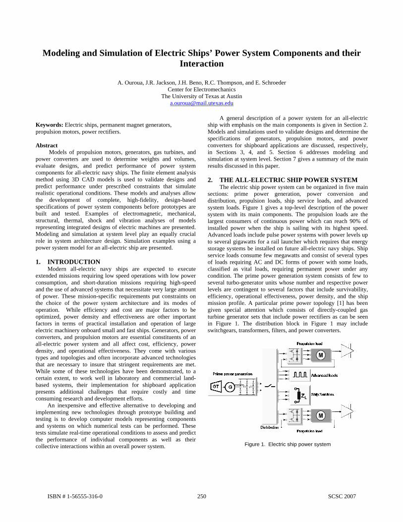
A general description of a power system for an all-electric ship with emphasis on the main components is given in Section 2. Models and simulations used to validate designs and determine the specifications of generators, propulsion motors, and power converters for shipboard applications are discussed, respectively, in Sections 3, 4, and 5. Section 6 addresses modeling and simulation at system level. Section 7 gives a summary of the main results discussed in this paper. 2. THE ALL-ELECTRIC SHIP POWER SYSTEM The electric ship power system can be organized in five main sections: prime power generation, power conversion and distribution, propulsion loads, ship service loads, and advanced system loads. Figure 1 gives a top-level description of the power system with its main components. The propulsion loads are the largest consumers of continuous power which can reach 90% of installed power when the ship is sailing with its highest speed. Advanced loads include pulse power systems with power levels up to several gigawatts for a rail launcher which requires that energy storage systems be installed on future all-electric navy ships. Ship service loads consume few megawatts and consist of several types of loads requiring AC and DC forms of power with some loads, classified as vital loads, requiring permanent power under any condition. The prime power generation system consists of few to several turbo-generator units whose number and respective power levels are contingent to several factors that include survivability, efficiency, operational effectiveness, power density, and the ship mission profile. A particular prime power topology [1] has been given special attention which consists of directly-coupled gas turbine generator sets that include power rectifiers as can be seen in Figure 1. The distribution block in Figure 1 may include switchgears, transformers, filters, and power converters.
Figure 1. Electric ship power system
ISBN # 1-56555-316-0 250 SCSC 2007
3. MODELING AND SIMULATION OF PRIME POWER GENERATION
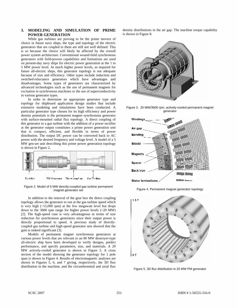
While gas turbines are proving to be the prime movers of choice in future navy ships, the type and topology of the electric generators that are coupled to them are still not well defined. This is so because the choice will likely be affected by the overall power system architecture. Conventional wound-field synchronous generators with field-proven capabilities and limitations are used on present-day navy ships for electric power generation at the 1 to 5 MW power level. At much higher power levels, as required for future all-electric ships, this generator topology is not adequate because of size and efficiency. Other types include induction and switched-reluctance generators which have advantages and disadvantages. Some types of generators are characterized by advanced technologies such as the use of permanent magnets for excitation in synchronous machines or the use of superconductivity in various generator types. In order to determine an appropriate generator type and topology for shipboard application design studies that include extensive modeling and simulations have been conducted. A particular generator type chosen for its high efficiency and power density potentials is the permanent magnet synchronous generator with surface-mounted radial flux topology. A direct coupling of this generator to a gas turbine with the addition of a power rectifier at the generator output constitutes a prime power generation unit that is compact, efficient, and flexible in terms of power distribution. The output DC power can be converted back to AC power with the desired frequency and voltage level. A model of a 5 MW gen-set unit describing this prime power generation topology is shown in Figure 2.
Figure 2. Model of 5 MW directly-coupled gas turbine permanent magnet generator set
In addition to the removal of the gear box the direct coupling topology allows the generator to run at the gas turbine speed which is very high (~15,000 rpm) at the few megawatt level but drops down to the 3600 rpm range for higher power levels (>20 MW) [2]. The high-speed case is very advantageous in terms of size reduction for synchronous generators since their output power is directly proportional to speed. A previous study of directly-coupled gas turbine and high-speed generator sets showed that the gain is indeed significant [3]. Models of permanent magnet synchronous generators at various power levels that are relevant to an 80 MW destroyer-type all-electric ship have been developed to verify designs, predict performance, and specify parameters, size, and materials. A 20 MW actively-cooled generator is shown in Figure 3. A cross section of the model showing the generator topology for 1 pole span is shown in Figure 4. Results of electromagnetic analyses are shown in Figures 5, 6, and 7 giving, respectively, the 3D flux distribution in the machine, and the circumferential and axial flux
density distributions in the air gap. The machine torque capability is shown in Figure 8.
Figure 3. 20 MW/3600 rpm, actively-cooled permanent magnet generator
Figure 4. Permanent magnet generator topology
Figure 5. 3D flux distribution in 20 MW PM generator
SCSC 2007 251 ISBN # 1-56555-316-0
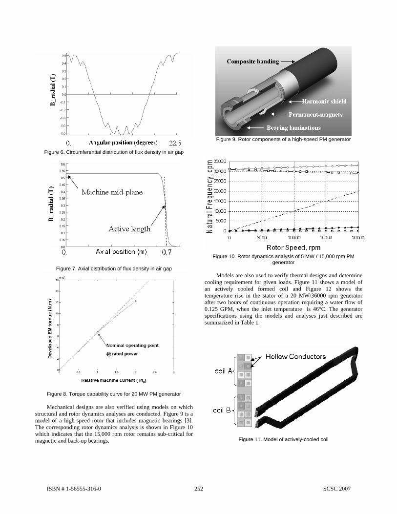
Figure 6. Circumferential distribution of flux density in air gap
Figure 7. Axial distribution of flux density in air gap
Figure 8. Torque capability curve for 20 MW PM generator Mechanical designs are also verified using models on which structural and rotor dynamics analyses are conducted. Figure 9 is a model of a high-speed rotor that includes magnetic bearings [3]. The corresponding rotor dynamics analysis is shown in Figure 10 which indicates that the 15,000 rpm rotor remains sub-critical for magnetic and back-up bearings.
Figure 9. Rotor components of a high-speed PM generator
Figure 10. Rotor dynamics analysis of 5 MW / 15,000 rpm PM
generator Models are also used to verify thermal designs and determine cooling requirement for given loads. Figure 11 shows a model of an actively cooled formed coil and Figure 12 shows the temperature rise in the stator of a 20 MW/36000 rpm generator after two hours of continuous operation requiring a water flow of 0.125 GPM, when the inlet temperature is 46°C. The generator specifications using the models and analyses just described are summarized in Table 1.
Figure 11. Model of actively-cooled coil
ISBN # 1-56555-316-0 252 SCSC 2007

Figure 12. Temperature rise in stator of a 20 MW, actively-cooled
PM generator
Table 1. Generator specifications
Machine type Surface Mounted Radial-Flux PM
Design Parameters
Machine rating Magnet material NdFeB Power 25 MVA Poles 16 Voltage 4160 VLL Phases 3 Power factor 0.82 Electric frequency 480 Hz Speed 3600 RPM Slots 96 Conductors / slot 16 Dimensions Current density 5960 A / in2
Stator O.D 1.04 m Winding resistance 2.75 mΩ Stator I.D 0.782 m Winding inductance 180 µH Air gap size 0.01 m Stator coils cooling Direct waterRotor O.D 0.762 m Stator core cooling Forced air Shield O.D 0.749 m Rotor cooling Forced air Magnet O.D 0.742 m Efficiency ~ 97% Back iron O.D 0.703 m Size Back iron I.D 0.653 m Weight 13 tonnes Active length 1.4 m Volume 7.5 m3
4. MODELING AND SIMULATION OF
PROPULSION MOTORS Propulsion motors in future naval electric ships have very large sizes due to their low speed and high power characteristics. They also tend to run more often at lower speeds making them less efficient. Advanced technologies, such as high temperature superconductivity, are being developed and their performance assessed for use in propulsion motors. Typical motor parameters of interest are in the 40 MW power level and 100-150 rpm speed range. Modeling and simulations help determine an effective comparison among various types of motors. A design study of propulsion motors to determine weights, volumes, and efficiencies of three types of propulsion motors has been completed and results are summarized in Table 2. Figures 13, 14, and 15 show, respectively, models of 40 MW wound-field synchronous, induction, and permanent magnet propulsion motors. The permanent magnet motor is clearly the smallest in size and most efficient, among the three motor types considered here, and represents an attractive option for further development. Superconducting propulsion motors, not included in this study, have potential for significant size and weight reduction as well.
Figure 13. 40 MW / 150 rpm wound-field synchronous motor
Figure 14. 40 MW / 150 rpm induction motor
Figure 15. 40 MW / 150 rpm permanent magnet synchronous motor
Table 2. Size and efficiency of 40 MW / 150 rpm propulsion motors
Motor type Vol. (m3) Weight (tonnes)
Efficiency (%)
Comments
Wound-field synchronous 181 370 ~96.5 Water-cooled
Conventional induction 120 390 ~97 Air-cooled Permanent-magnet synchronous 100 199 ~97.5 Water-cooled
An inherent factor that adds to the size of electric machines used on navy ships is the high shock loads they may be subjected to. An analysis that allows an evaluation of stresses and displacements under such high loads through modeling and simulation is necessary in order to ascertain that the design is viable. Figures 16 is a model of a 20 MW/ 150 rpm permanent magnet propulsion motor and Figures 17 and 18 show stress levels and rotor deflections when vertical, transverse, and axial shock loads are applied simultaneously. The stress analysis verifies that the material strength is adequate. The deflection analysis insures that under shock loads the deflected rotor does not come in contact with the stator laminations and that the air gap size is optimum. The model also allows frequency response analysis as shown in
SCSC 2007 253 ISBN # 1-56555-316-0
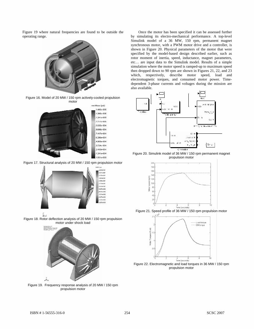
Figure 19 where natural frequencies are found to be outside the operating range.
Figure 16. Model of 20 MW / 150 rpm actively-cooled propulsion
motor
Figure 17. Structural analysis of 20 MW / 150 rpm propulsion motor
Figure 18. Rotor deflection analysis of 20 MW / 150 rpm propulsion
motor under shock load
Figure 19. Frequency response analysis of 20 MW / 150 rpm
propulsion motor
Once the motor has been specified it can be assessed further by simulating its electro-mechanical performance. A top-level Simulink model of a 36 MW, 150 rpm, permanent magnet synchronous motor, with a PWM motor drive and a controller, is shown in Figure 20. Physical parameters of the motor that were specified by the model-based design described earlier, such as rotor moment of inertia, speed, inductance, magnet parameters, etc… are input data to the Simulink model. Results of a simple simulation where the motor speed is ramped-up to maximum speed then dropped down to 90 rpm are shown in Figures 21, 22, and 23 which, respectively, describe motor speed, load and electromagnetic torques, and consumed motor power. Time-dependent 3-phase currents and voltages during the mission are also available.
Figure 20. Simulink model of 36 MW / 150 rpm permanent magnet
propulsion motor
Figure 21. Speed profile of 36 MW / 150 rpm propulsion motor
Figure 22. Electromagnetic and load torques in 36 MW / 150 rpm
propulsion motor
ISBN # 1-56555-316-0 254 SCSC 2007

Figure 23. Consumed power by 36 MW /150 rpm propulsion motor
during speed ramp-up and ramp-down
Modeling and simulations also allow a clear description and realistic assessment of innovative approaches that aim at improving the performance of electric machines which potential benefits cannot, otherwise, be fully realized and appreciated. An example is the improvement of power density and efficiency that can be achieved by integrating power electronics components inside the inherently hollow rotor of high power propulsion motors. This can be seen in Figure 24 where motor drive components are integrated inside the rotor of a 20 MW, 150 rpm propulsion motor [4].
Figure 24. 20 MW / 150 rpm propulsion motor with integrated power
electronics 5. MODELING AND SIMULATION OF POWER
ELECTRONICS Power electronics play a major role in converting, conditioning, and distributing power to various loads onboard an all-electric navy ship. As is the case for electric machines, power electronics are voluminous, heavy, inefficient, and require adequate thermal management for proper operation. Considerable advances have been made in the performance of power semiconductor devices but high-power motor drives and rectifiers, for example, are still large and require a major improvement for effective shipboard application. Modeling and simulation of power electronics components allow the determination of size, efficiency, cooling requirement, and performance. Models of 6- and 12-pulse rectifiers have been developed for the generators considered in this study. Figure 25 shows a 51 MVA 6-pulse rectifier for the 40 MW
permanent magnet generator. The rectifier was designed using commercial high-performance diodes [5] and thermal models of the water-cooled heat sinks show that a water flow of 1 gpm is required to keep the temperature within normal operating condition.
Figure 25. 51 MVA 6-pulse diode rectifier for 40 MW PM generator
Rectifier performances in terms of the total harmonic distortion (THD) have been determined using Simulink models when the load is purely resistive. Figure 26 is a Simulink circuit model representing 6-pulse rectifiers. The parameters of the model are those of actual commercial diodes and generators parameters that are considered in this paper.
Figure 26. 6-pulse rectifier model with resistive load
Harmonic distortions in electric power systems cause additional losses and can damage the generator winding insulation if not properly designed. One way of reducing the THDs is to increase the number of pulses which in turn results in larger and heavier rectifier assemblies. Table 3 gives a summary of rectifier performances for various power levels and rectifier topologies. Figure 27 shows models of a 5 MW gas turbine generator set with 6- and 12-pulse rectifiers for comparison. The 12-pulse rectifier also requires a phase-shifting transformer. Table 4 gives size and performance comparisons between 6- and 12-pulse rectifiers. Size and weight are obtained through designs using commercial power diodes.
SCSC 2007 255 ISBN # 1-56555-316-0
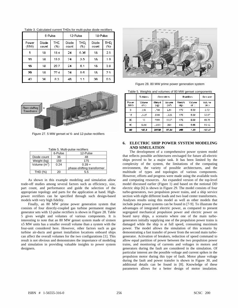
Table 3. Calculated current THDs for multi-pulse diode rectifiers
Figure 27. 5 MW genset w/ 6- and 12-pulse rectifiers
Table 5. Multi-pulse rectifiers 6-Pulse 12-Pulse
Diode count 36 48 Weight (kg) 159 175 Volume (m3) 0.24 0.39 +
phase-shifting transformer THD (%) 20 5.5
As shown in this example modeling and simulation allow trade-off studies among several factors such as efficiency, size, part count, and performance and guide the selection of the appropriate topology and parts for the application at hand. High-power rectifiers can be specified through such design-based models with very high fidelity. Finally, an 80 MW prime power generation system that consists of four directly-coupled gas turbine permanent magnet generator sets with 12-pulse rectifiers is shown in Figure 28. Table 5 gives weight and volumes of various components. It is interesting to note that an 80 MW genset system made of sixteen x5 MW units has a smaller overall volume than a system with the four-unit considered here. However, other factors such as gas turbine air-ducts and genset installation locations onboard ships can affect the overall volumes for the two configurations [1]. This result is not obvious and demonstrates the importance of modeling and simulation in providing valuable insights to power system designers.
Figure 28. 80 MW prime power generation system
Table 5. Weights and volumes of 80 MW genset components
6. ELECTRIC SHIP POWER SYSTEM MODELING
AND SIMULATION The development of a comprehensive power system model that reflects possible architectures envisaged for future all-electric ships proved to be a major task. It has been limited by the complexity of the system, the limitations of the computing environment, the variety of possible architectures, and the multitude of types and topologies of various components. However, efforts and progress were made using the available tools and computing resources. An expanded version of the top-level model discussed earlier (Figure 1) and based on the notional DD electric ship [6] is shown in Figure 29. The model consists of four turbo-generators, two propulsion power trains, and a ship service section with eight different loads and two load center transformers. Analyses results using this model as well as other models that include pulse power systems can be found in [7-9]. To illustrate the advantages of integrated electric power, as compared to present segregated mechanical propulsion power and electric power on board navy ships, a scenario where one of the main turbo-generators initially supplying one of the propulsion power trains is damaged while the ship is at full speed, consuming maximum power. The model allows the simulation of this scenario by demonstrating a fast transfer of power from the second main turbo-generator. Activation of breakers, reduction of speed command to allow equal partition of power between the two propulsion power trains, and monitoring of currents and voltages in motors and generators during the fault are considered in the simulation. Of particular interest are the possible voltage and current spikes in the propulsion motor during this type of fault. Motor phase voltage during the fault and power transfer is shown in Figure 30, and additional details can be found in [8]. Knowledge of these parameters allows for a better design of motor insulation.
ISBN # 1-56555-316-0 256 SCSC 2007
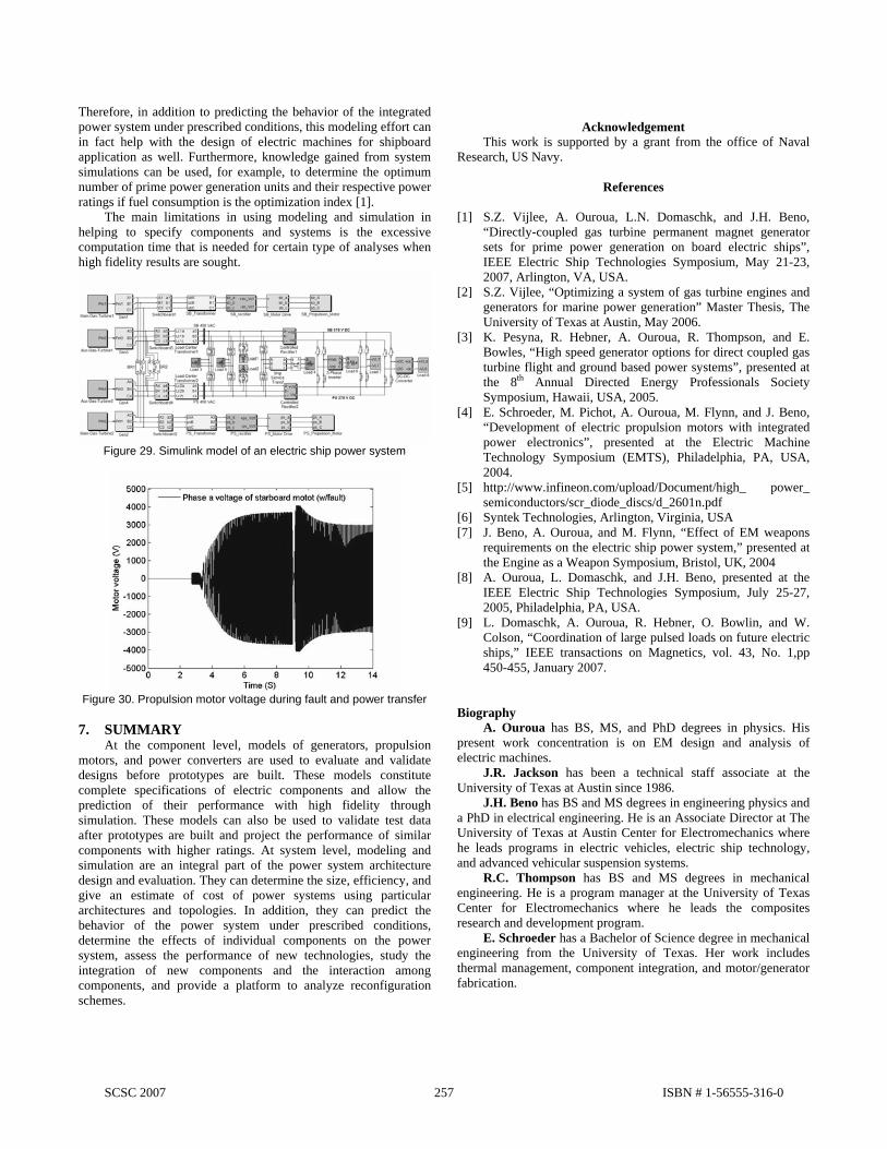
Therefore, in addition to predicting the behavior of the integrated power system under prescribed conditions, this modeling effort can in fact help with the design of electric machines for shipboard application as well. Furthermore, knowledge gained from system simulations can be used, for example, to determine the optimum number of prime power generation units and their respective power ratings if fuel consumption is the optimization index [1]. The main limitations in using modeling and simulation in helping to specify components and systems is the excessive computation time that is needed for certain type of analyses when high fidelity results are sought.
Figure 29. Simulink model of an electric ship power system
Figure 30. Propulsion motor voltage during fault and power transfer
7. SUMMARY At the component level, models of generators, propulsion motors, and power converters are used to evaluate and validate designs before prototypes are built. These models constitute complete specifications of electric components and allow the prediction of their performance with high fidelity through simulation. These models can also be used to validate test data after prototypes are built and project the performance of similar components with higher ratings. At system level, modeling and simulation are an integral part of the power system architecture design and evaluation. They can determine the size, efficiency, and give an estimate of cost of power systems using particular architectures and topologies. In addition, they can predict the behavior of the power system under prescribed conditions, determine the effects of individual components on the power system, assess the performance of new technologies, study the integration of new components and the interaction among components, and provide a platform to analyze reconfiguration schemes.
Acknowledgement
This work is supported by a grant from the office of Naval Research, US Navy.
References
[1] S.Z. Vijlee, A. Ouroua, L.N. Domaschk, and J.H. Beno, “Directly-coupled gas turbine permanent magnet generator sets for prime power generation on board electric ships”, IEEE Electric Ship Technologies Symposium, May 21-23, 2007, Arlington, VA, USA.
[2] S.Z. Vijlee, “Optimizing a system of gas turbine engines and generators for marine power generation” Master Thesis, The University of Texas at Austin, May 2006.
[3] K. Pesyna, R. Hebner, A. Ouroua, R. Thompson, and E. Bowles, “High speed generator options for direct coupled gas turbine flight and ground based power systems”, presented at the 8th Annual Directed Energy Professionals Society Symposium, Hawaii, USA, 2005.
[4] E. Schroeder, M. Pichot, A. Ouroua, M. Flynn, and J. Beno, “Development of electric propulsion motors with integrated power electronics”, presented at the Electric Machine Technology Symposium (EMTS), Philadelphia, PA, USA, 2004.
[5] http://www.infineon.com/upload/Document/high_ power_ semiconductors/scr_diode_discs/d_2601n.pdf
[6] Syntek Technologies, Arlington, Virginia, USA [7] J. Beno, A. Ouroua, and M. Flynn, “Effect of EM weapons
requirements on the electric ship power system,” presented at the Engine as a Weapon Symposium, Bristol, UK, 2004
[8] A. Ouroua, L. Domaschk, and J.H. Beno, presented at the IEEE Electric Ship Technologies Symposium, July 25-27, 2005, Philadelphia, PA, USA.
[9] L. Domaschk, A. Ouroua, R. Hebner, O. Bowlin, and W. Colson, “Coordination of large pulsed loads on future electric ships,” IEEE transactions on Magnetics, vol. 43, No. 1,pp 450-455, January 2007.
Biography A. Ouroua has BS, MS, and PhD degrees in physics. His present work concentration is on EM design and analysis of electric machines. J.R. Jackson has been a technical staff associate at the University of Texas at Austin since 1986. J.H. Beno has BS and MS degrees in engineering physics and a PhD in electrical engineering. He is an Associate Director at The University of Texas at Austin Center for Electromechanics where he leads programs in electric vehicles, electric ship technology, and advanced vehicular suspension systems. R.C. Thompson has BS and MS degrees in mechanical engineering. He is a program manager at the University of Texas Center for Electromechanics where he leads the composites research and development program. E. Schroeder has a Bachelor of Science degree in mechanical engineering from the University of Texas. Her work includes thermal management, component integration, and motor/generator fabrication.
SCSC 2007 257 ISBN # 1-56555-316-0