modeling and simulation computational modelling of
TRANSCRIPT

MODELING AND SIMULATION
COMPUTATIONAL MODELLING OF SUBMERGED-ARC FURNACE BURDEN BEHAVIOUR
Q. G. Reynolds, K. Bisaka
Pyrometallmgy Division, Mintek. Private Bag X3015, Randburg, 2125 [email protected].~
ABSTRACT
Submerged-arc furnaces (SAFs) are used extensively in many ore smelting industries. Process applications for such furnaces have included ferrochromium, ferronickel, silicon, ferromanganese, platinum group metals, and many others.
A key operating principle of the SAF is the presence of a moving bed, or burden, of solid feed material above the molten bath. This burden completely covers the molten bath and electrodes, often to a depth of several metres. The burden is constantly consumed from below by reaction and melting at the hot zones around the electrode tips, and replenished from above with fresh feed from the charging system. The circular-design SAF generally used for ferroalloys smelting uses three electrodes on a circular pitch, and alternating current, to supply power to the unit. The tips of the electrodes penetrate the molten bath and maintain its temperature by resistive heating as current is conducted between electrodes.
Due to the strong evolution of gases from the reduction processes happening at the level of the molten bath, it is a requirement that SAFs be fed with lumpy feed materials containing mostly particle sizes in the range between 20 and 50 mm. This ensures that the porosity of the burden is kept constant and allows process gases to escape to the extraction system.
Many of the problematic conditions in the operation of SAFs are related to particulate-level and time-dependent behaviour. Discrete element method (DEM) modelling was applied to the study of the burden dynamics in the SAF, including motion of particulate material, energy transfer, gas flow, and chemical reactions, to provide insights that are missed by traditional continuum-type models. A number of snapshots from the burden dynamics are presented and discussed in this paper.
KEYWORDS: Submerged-arc furnace, burden, computational modelling, discrete element method
INTRODUCTION
Submerged-arc furnaces (SAFs) are used extensively in many ore smelting industries. Process applications for such furnaces have included platinum group metals, ferronickel, ferrochromium, silicon, ferromanganese, and many other commodities.
SAFs are typically found in one of two designs - rectangular or circular. The rectangular design uses six electrodes arranged in a line, whereas the circular design uses three electrodes on a circular pitch. Schematic views of both types are shown in figure 1. Both designs use alternating current to supply power to the unit, with each electrode (or pair of electrodes in the case of rectangular furnaces) connected to a single phase. Electrodes are continually consumed and are generally of the SHderberg type, which are baked to graphite in situ by the high temperatures in the furnace vessel. The tips of the electrodes penetrate the molten bath and maintain its temperature by resistive heating as current is conducted between electrodes.
The thirteenth International Ferroalloys Congress Efficient technologies in ferroalloy industry
821
June 9 - 13, 2013 Almaty, Kazakhstan

MODELING AND SIMULATION
Figure 1: Submerged-arc furnace designs, top and side views
A key operating principle of the SAF is the presence of a moving bed of solid feed material above the molten bath. This bed is known as the burden and completely covers the molten bath and electrodes, often to a depth of several metres. The burden is constantly consumed from below by reaction and melting at the hot zones around the electrode tips, and replenished from above with fresh feed from the charging system. Several experimental studies of the contents of SAF vessels (including the burden) have been made via furnace dig-outs [1,2], and have revealed a complex arrangement of distinct regions including segregation of the burden layer as the feed material moves down toward the smelting zones.
Due to the strong evolution of gases by the chemical reactions happening at the level of the molten bath, it is a requirement that SAFs be fed with "lumpy" feed materials containing mostly large particle sizes (> 20-50 mm). This ensures that the porosity of the burden is maintained and allows process gases to escape safely to the off-gas handling systems.
Operating with a burden covering and insulating the molten bath in the furnace affords certain advantages to the SAF. However, under certain conditions, the behaviour of the particulate material in the burden bed can also cause problems. These can include:
• Bypassing and segregation, in which different feed materials or size fractions move through the burden at different speeds and directions - this leads to accumulation and dead zones, affecting process efficiency.
• Feeding of electrically conductive material, such as carbon-based reductants, can establish inter-electrode conduction paths through the burden. This results in undesirable arcing and additional resistive heating within the burden layer.
• Sintering or other mechanisms for reducing the porosity of the burden bed, particularly in the hot smelting zones near to the electrode tips - this can cause containment of process gases and the undesirable build-up of pressure, resulting in dangerous eruptions and explosions.
Many existing modelling studies of SAF operation treat the burden layer as a simple lumped parameter system, if it is considered at all. Such approaches are perfectly adequate for modelling of the steady-state, bulk behaviour of the burden, particularly as it pertains to furnace control aspects. Unfortunately, many of the problematic conditions outlined above are related to particulate-level and time-dependent behaviour, and there is some scope for different approaches to be investigated.
The discrete element method (DEM) [3] is a computational modelling technique which calculates the trajectory of each individual element of a particulate medium according the forces and collisions acting on it. Application of DEM to the study of the burden behaviour in blast furnaces [ 4-6] has been successful, and can provide insights that are missed by traditional continuum-type models7 which treat the burden as a continuous medium. Many phenomena in blast furnace burdens closely parallel those occurring in the SAF, including motion of particulate material, energy transfer, gas flow, and chemical reactions. The development of DEM models of the
The thirteenth International Ferroalloys Congress Efficient technologies in ferroalloy industry
822
June 9 - 13, 2013 Almaty, Kazakhstan

MODELING AND SIMULATION
burden motion in these :furnaces was therefore deemed worthy of further investigation.
MODEL DEVELOPMENT
The rectangular SAF design was chosen as the focus of this study. A diagram of the furnace region used in the DEM burden behaviour model is shown in figure 2. The model geometry takes advantage of a number of symmetry planes around and between the electrodes (shown as dashed lines) to reduce the required size of the region to be modelled. Only the burden itself is considered in the model, with the molten bath surface, symmetry planes, and physical surfaces all treated as solid walls. The curved electrode is approximated using a triangulated surface.
Figure 2: Rectangular furnace model geometry
A heterogeneous feed material consisting of a mixture of spherical ore and reductant particles is input into the model at specified locations. The ore is typically a rocky oxide mineral bearing the element(s) of interest, and the reductant is generally a carbonaceous material such as coal or coke. Both are consumed at a specified rate at the bath surface in a region surrounding the electrode (the melt zone), to simulate melting and reaction. After an initial transient period, during which the furnace burden fills to the level of the input feed-ports, the furnace becomes choke-fed, with the consumption rate effectively controlling the feed rate. The feed-ports are simulated using small cylindrical volumes into which particles are inserted as the simulation proceeds. The location of the feed-ports in the model and the geometry of the region are shown in figure 3, for a furnace 18 m x 5 m in size with 1.5 m diameter electrodes.
y
(.;'"'\ x-0.375m v y - 1.125!!!
2-5m
---------------··-··--....~ 0 x-0.8385.IJ!
x
·-.......... " y =0.8385 !!!
"'· ~ \. (;\ x • 1.9!!!. V y =O.Hm
:.;::;. \ ~o \ 0 x- 1.125m
'::> \ y - 0.375 m ~ \
\.
Figure 3: DEM model region
The thirteenth International Ferroalloys Congress Efficient technologies in ferroalloy industry
823
June 9 - 13, 2013 Almaty, Kazakhstan

MODELING AND SIMULATION
The material properties and other parameters used in the DEM model of the rectangular SAF are given in tables 1 and 2. It is important to note that many of the mechanical properties of ore and reductant materials typically used in the ferro-alloys and other smelting industries are quite poorly known, and, as a result, generic or indicative values based on similar materials have been used here [8,9,10,11,12]. The use of a very low Young's modulus (true values are of the order of GPa) is a necessary numerical approximation to ensure that reasonable time step sizes could be used in the DEM model; the effect is to allow adjacent particles to overlap to a small degree, however this is anticipated to have a minimal effect on the results. The coefficients of rolling friction due to particle rotation were assumed to be negligible for the purposes of this simulation.
Table 1: DEM model parameters
Parameter Value Parameter Value Region dimensions 2.5m x 1.5m x 1.5m Collision model Hertzian
Electrode radius 0.75m Consumption rate 20-25 kg/s Melt zone radius lm Time step 10-4 s
Initial feedrate 60 kg/s Number of time steps 4 OOO OOO
Table 2: Material properties
Parameter Ore Reductant Density 3500 kg/mj 1500 kg/mj Size distribution 30-50mm 30-50mm Poisson's ratio 0.25 0.35 Young's modulus 7MPa 7MPa Coefficient of restitution (vs ore) 0.5 0.4 Coefficient of restitution (vs reductant) 0.4 0.3 Coefficient of friction (vs ore) 0.7 0.7 Coefficient of friction (vs reductant) 0.7 0.7
Using these data, the effect of reductant mass fraction in the feed on physical segregation of the burden due to particle motion as well as the electrical behaviour was studied. Particle mixtures with reductant mass fractions between 5% and 40% were specified as feed material in the model.
In order to determine if there is electrical contact between adjacent electrodes in the DEM model of the burden at any given time, the entire ensemble of particles in the model must be analysed to determine the contact network. This is simply the set of all conductive particles (in this case, the reductant) directly or indirectly in physical contact with the electrode surfuce, as shown in figure 4. The size and extension in space of the contact network determines if a conduction path between electrodes exists.
The algorithm for determining the contact network from a set of particle positions, radii, and compositions representing an instantaneous snapshot of the burden is simple in principle but computationally intensive. The first step is removal of all non-conducting particles, so that only the subset of particles capable of conducting electricity remains. The algorithm then performs a collision test between all particles in this subset and the triangular elements of the electrode surface - any particles touching the electrode are flagged with a contact number, nc, of 1, and removed from the subset. In the following step, the algorithm performs collision detection between all particles with nc = 1, and all remaining particles in the subset. Any particles in contact with particles of 11c = 1 are flagged with n0 = 2, and removed from the subset. The previous step is then iterated for
The thirteenth International Ferroalloys Congress Efficient technologies in ferroalloy industry
824
June 9 - 13, 2013 Almaty, Kazakhstan

MODELING AND SIMULATION
nc = 3, 4, 5 ... until nc = N is reached, at which no further particles are found to be in contact with the particles flagged nc = N-1. At this point the algorithm halts, and writes out the parameters of all particles in the collision network to a file for analysis and visualisation purposes.
Electrode
particles in - contact network
Figure 4: Diagram of contact network
The open-source LIGGGHTS [13] software was used to implement the DEM modelling study. LIGGGHTS has been developed using robust particle calculation algorithms derived from advanced molecular dynamics tools, and is able to scale to systems with very large numbers of particles, by making efficient use of parallel computing facilities. The software uses a simple input script file to set up the geometry and particle properties for a simulation, and control its execution and data output. LIGGGHTS version 1.5 was used for the results generated in this work (the software is undergoing active development, and is currently at version 2.2).
RESULTS AND DISCUSSION
Visualisations of the three-dimensional particle assembly for two cases, one with 10% reductant by mass in the feed, and one with 30% reductant by mass in the feed, are shown in figures 5 to 10 for various times. Reductant particles are coloured blue, while ore particles are coloured green.
The overall fill patterns and developed burden shape in the model region are similar once the choke-fed steady state is reached, although it is obvious that the bed contains more reductant particles in the case where they form a higher fraction of the incoming feed. Evolution of the burden inventory for the two cases is shown in figures 11 and 12. Total mass in the burden at equilibrium is seen to be somewhat lower in the case of higher reductant fraction. This is due to the lower density of the reductant particles relative to the ore.
Figure 5: 10% reductant, 20s
The thirteenth International Ferroalloys Congress Efficient technologies in ferroalloy industry
825
Figure 6: 30% reductant, 20s
June 9 - 13, 2013 Almaty, Kazakhstan

MODELING AND SIMULATION
Cl ...:
~ _g c: !11 .E
6000
sooo
4000
3000
2000
1000
Figure 7: 10% reductant, 15 Os
Figure 9: 10% reductant, 400s
OreReductant ---- ----
.. .... ----------------------------------------- ----o ....... =---~------·..___._ _ _.____.__.....____.___. 0 so 100 1 so 200 2SO 300 350 400
time, s
Figure 11: Inventory history for 10% reductant
Figure 8: 10% reductant, l 50s
r:/ ····.·.·.····.· .. ··.· • \~ . ·; _·~ ... ~~--- -.. . : :.. --~ ·_ .. I
·.. . .. · .... _ ... · -_ ... . . - ' "" . ~ . - .. . . '. . , . . , . ... .. .. _
. . ..... ... . .. . .... . . ..... . -· -· . --(.
i
Figure 10: 30% reductant, 400s
4SOO ~~-~~--~-~~~
4000
3SOO
OreReciJctant -- -----·
~ 3000
~ 2SOO
~
-~ 2000 ----- --------------1500 -~-------.. --
·:: __ ./_/···
0 so 100 1 so 200 250 300 350 400 time, s
Figure 12: Inventory history for 30% reductant
Total number of particles in the simulation once the equilibrium state was reached was roughly 100 OOO in all cases. Calculation of the full 400 s of model time typically took 40 to 50 hours on an Intel Core 2 quad-core processor, running LIGGGHTS with four OpenMPI threads.
Material segregation behaviour The lower density of the reductant leads to a certain degree of physical separation of the feed
at the burden surface, which is subsequently carried down into the bed as it is consumed. Reductant particles tend to accumulate preferentially at the bases of the heaps of feed that form underneath each of the feed-ports. Immediately below the feed-ports the reductant concentration is therefore
The thirteenth International Ferroalloys Congress Efficient technologies in ferroalloy industry
826
June 9 - 13, 2013 Almaty, Kazakhstan

MODELING AND SIMULATION
lowest, and the ore concentration the highest. Some visualisations of the burden model showing only the reductant particles are shown in
figures 13 to 16, at various feed mass fractions. All of these have been taken once the burden has reached equilibrium, at 400 s model time.
Figure 13: Reductant only, 5% reductant, 400s Figure 14: Reductant only, 10% reductant, 400s
Figure 15: Reductant only, 20% reductant, 400s Figure 16: Reductant only, 40% reductant, 400s
Although it is not very clear in the images above, the particles are clustered to some degree at the boundaries between the feed-port locations. In order to demonstrate this effect more quantitatively, the mass fraction ofreductant was calculated directly at various locations throughout the model region. This data is presented in two-dimensional form (top-down) in figures 17 to 20. The dark region at lower left in all cases is the space occupied by the electrode.
0.1
0.09
0.08
0.07
0.06
0.05
O.Q4
0.03
Figure 17: Local reductant mass fraction, 5% reductant in feed, 400s
The thirteenth International Ferroalloys Congress Efficient technologies in ferroalloy industry
827
02
0 18
0.16
0 14
0. 12
0. 1
0.08
0.06
Figure 18: Local reductant mass fraction, 10% reductant in feed, 400s
June 9 - 13, 2013 Almaty, Kazakhstan

MODELING AND SIMULATION
0.4
0.35
0.3
0 .25
0 .2
0 .15
0 .1
Figure 19: Local reductant mass fraction, 20% reductant in feed, 400s
08
0.7
06
05
0.4
0.3
0.2
Figure 20: Local reductant mass fraction, 40% reductant in feed, 400s
It can be seen that for a wide range of feed compositions, the reductant in the burden preferentially concentrates at the borders of"cells" defined by the feed-port locations (figure 3), the furnace walls and electrodes, and the planes of symmetry. The depleted regions directly beneath the feed-ports can have as little as half the reductant concentration in the feed, while the enriched areas at the cell boundaries often have more than double the feed concentration.
This segregation effect may cause (among other things) difficulties in controlling intra-burden reactions necessary for the process, and uneven sintering and bed heating may result. This emphasises the importance of correct and accurate placement of feed-ports on SAFs during both the design and operation phases of the furnace.
Contact network behaviour Contact networks were calculated for all model cases, using the fully developed burden
profile at time 400 s. Only the reductant was considered to be electrically conductive. Various views of the reductant particles that form part of the contact networks for the cases of 10% and 20% reductant in the feed are shown in figures 21 to 24.
Figure 21: Reductant contact network, 10% reductant in feed, 400s
Figure 23: Reductant contact network, 10% reductant in feed, 400s
The thirteenth International Ferroalloys Congress Efficient technologies in ferroalloy industry
Figure 22: Reductant contact network, 20% reductant in feed, 400s
Figure 24: Reductant contact network, 20% reductant in feed, 400s
828
June 9 - 13, 2013 Almaty, Kazakhstan
MODELING AND SIMULATION
Burden models with lower fractions of reductant in the feed display very little connectivity, with only a few particles close to the surface of the electrode in electrical contact. By contrast, the models at higher reductant fractions in the feed are fully connected, with the majority of the reductant particles in the burden forming part of the contact network with the electrode. In these cases, some short-circuiting and conduction of electricity through the burden layer would be unavoidable.
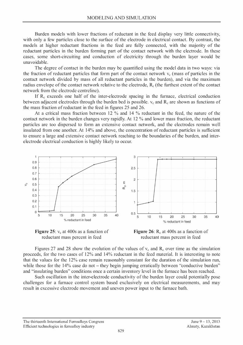
The degree of contact in the burden may be quantified using the model data in two ways: via the fraction of reductant particles that form part of the contact network Ve (mass of particles in the contact network divided by mass of all reductant particles in the burden), and via the maximum radius envelope of the contact network relative to the electrode, Re (the furthest extent of the contact network from the electrode centreline).
If Re exceeds one half of the inter-electrode spacing in the furnace, electrical conduction between adjacent electrodes through the burden bed is possible. Ve and Re are shown as functions of the mass fraction ofreductant in the feed in figures 25 and 26.
At a critical mass fraction between 12 % and 14 % reductant in the feed, the nature of the contact network in the burden changes very rapidly. At 12 % and lower mass fraction, the reductant particles are too dispersed to form an extensive contact network, and the electrodes remain well insulated from one another. At 14% and above, the concentration ofreductant particles is sufficient to ensure a large and extensive contact network reaching to the boundaries of the burden, and interelectrode electrical conduction is highly likely to occur.
>u
0.9
0.8
0.7
0.6
0.5
0.4
0.3
0.2
0.1
0 5 10 15 20 25 30 35
% reductant in feed
Figure 25: Ve at 400s as a function of reductant mass percent in feed
40
E ;;,
a:
2.5
2
1.5
0.5 ~---~-~-----~-~ 5 10 15 20 25 30 35 40
% reductanl in feed
Figure 26: Re at 400s as a :function of reductant mass percent in feed
Figures 27 and 28 show the evolution of the values ofve and Re over time as the simulation proceeds, for the two cases of 12% and 14% reductant in the feed material. It is interesting to note that the values for the 12% case remain reasonably constant for the duration of the simulation run, while those for the 14% case do not - they begin jumping erratically between "conductive burden" and "insulating burden" conditions once a certain inventory level in the furnace has been reached.
Such oscillation in the inter-electrode conductivity of the burden layer could potentially pose challenges for a furnace control system based exclusively on electrical measurements, and may result in excessive electrode movement and uneven power input to the furnace bath.
The thirteenth International Ferroalloys Congress Efficient technologies in ferroalloy industry
829
June 9 - 13, 2013 Almaty, Kazakhstan

MODELING AND SIMULATION
0.5
0.45
0.4
0.35
0.3
>"' 0.25
0.2
0.15
0.1
0.05 ·'. 0 200
12% reductant -14% reductant ••••••••
250 300
1ime,s
350 400
Figure 27: Variation ofvc with time, for reductant mass fractions 12 % and 14 %
CONCLUSIONS
<> a:
3.5 ~-~--~--~--~
3
2.5
2
1.5
200
12% reductant -14"/o reductant ••••••••
250 300
time, s 350 400
Figure 28: Variation ofR: with time, for reductant mass fractions 12 % and 14 %
The implementation of a discrete element method model of the burden behaviour in submerged-arc furnaces was successfully achieved, and has produced several novel results. Some segregation of the burden as a result of feeding a mixture of materials of different physical properties was observed, with particles of lower density accumulating at the borders of cells defined by the feed-port locations. A study of the inter-electrode electrical conduction was made possible by contact network analysis, and results were obtained suggesting that a given furnace operation may have a "critical" reductant loading at which the burden can change rapidly between being electrically insulating and being electrically conductive.
There is much scope for further work on understanding furnace burden behaviour using the approach discussed here. Study of the long-term behaviour of burden beds (model times greater than 400 s) is advised, to verify that the phenomena observed in this work are not related to the initial conditions used. Additionally, energy transfer and chemical reaction effects are critical to many additional phenomena in furnace burden behaviour, and extension of the discrete element models to account for these effects would be highly desirable.
ACKNOWLEDGEMENTS
This work is published by permission of Mintek. The authors wish to acknowledge the CSIR/Meraka Institute Centre for High Performance Computing for providing computational resources during the development of the SAF burden model
REFERENCES
1. Barcza, N.A., Koursaris, A., See, J.B. and Gericke, W.A., The 'dig-out' of a 75 MVA highcarbon ferromanganese electric smelting furnace, Electric Furnace Conference Proceedings, vol. 37, 1979, pp 19-33.
2. Dyason, D.J. and See, J.B., Burden movement in submerged-arc ferromanganese furnaces, Met Trans B, vol. 12 no. 1, 1981, pp 149-160.
3. Cundall, P.A. and Strack, 0.D.L., A discrete numerical model for granular assemblies, Geotechnique, vol. 29, 1979, pp 47--65.
4. Nouch~ T., Sato, M. and Takeda, K., Process analysis for blast furnaces by the discrete element method, JFE Technical Report, no. 13, May 2009, pp 28-33.
The thirteenth International Ferroalloys Congress Efficient technologies in ferroalloy industry
830
June 9 - 13, 2013 Almaty, Kazakhstan

MODELING AND SIMULATION
5. Mio, H., Yamamoto, K., Shlmosaka, A., Shirakawa, Y. and Hidaka, J., Modeling of solid particle flow in blast furnace considering actual operation by large-scale discrete element method, ISIJ International, vol. 47 no. 12, 2007, pp 1745-1752.
6. Zhou, Z. Y., Zhu, H. P., Yu, A. B., Wright, B., Pinson, D., and Zulli, P. Discrete particle simulation of solid flow in a model blast furnace, ISIJ International, vol. 45, 2005, pp 1828-1837.
7. Zhang, S.J., Yu, A., Zull~ P., Wright, B. and Austin, P., Numerical simulation of solids flow in a blast furnace, 2nii International Conference on CFD in the Minerals and Process Industries, Melbourne (Australia), 6-8 December 1999, pp 411-416.
8. Szabo, T.L., A representative Poisson's ratio for coal, International Journal of Rock Mechanics and Mining Sciences & Geomechanics Abstracts, vol. 18 no. 6, 1981, pp 531-533
9. Gercek, H., Poisson's ratio value for rocks, International Journal of Rock Mechanics & Mining Sciences, vol. 44, 2007, pp 1-13.
10. Sand, A., Rosenkranz, J. and Kuyumcu, H. Z., DEM modelling and simulation of coal compaction by stamping, Conference in Minerals Engineering 2012, Lulea (Sweden), 8-9 February 2012, pp 119-136.
11. Antoniou, A.A., Psarropolous, P.N. and Karvelis, P.D., Impact of rockfalls on buried pipelines, i 11 Pipeline Technology Conference, Hannover (Germany), 28-30 March 2012, http://www.pipeline-conference.com/sites/default/files/papers/ptc _ 2012 _ Antoniou.pdf.
12. Byerlee, J., Friction of rocks, Pure and Applied Geophysics, vol. 116, 1978, pp 615-626. 13. http://www.liggghts.com
The thirteenth International Ferroalloys Congress Efficient technologies in ferroalloy industry
831
June 9 - 13, 2013 Almaty, Kazakhstan

MODELING AND SIMULATION
The thirteenth International Ferroalloys Congress Efficient technologies in ferroalloy industry
832
June 9 - 13, 2013 Almaty, Kazakhstan