modeling and comparison of machine and converter losses for pwm and pam … · 2015-11-09 ·...
TRANSCRIPT

Celeroton AG Industriestrasse 22 8604 Volketswil
Switzerland
© 2014 IEEE
IEEE Transactions on Industry Applications, Vol. 50, No. 2, pp. 995-1006, March/April 2014.
Modeling and Comparison of Machine and Converter Losses for PWM and PAM in High-Speed Drives
L. Schwager ABB Discrete Automation and Motion, Switzerland A. Tüysüz ETH Zurich, Switzerland C. Zwyssig Celeroton AG, Switzerland J. W. Kolar ETH Zurich, Switzerland
This material is posted here with permission of the IEEE. Such permission of the IEEE does not in any way imply IEEE endorsement of any of Celeroton’s products or services. Internal or personal use of this material is permitted. However, no recopying, reprinting, redistributing or reselling is permitted without the written consent from IEEE. By choosing to view this document, you agree to all provisions of the copyright laws protecting it.

Abstract – For variable speed drives the interaction of the
machine and the converter is becoming increasingly important,
especially for high speed applications, mainly due to the effect
of the converter modulation on the machine losses. The
allocation of the losses to different components of the drive
system needs to be known in order to choose the ideal machine
and modulation combination. In this paper, individual models
are introduced for calculating the rotor, copper, core losses of
the machine as well as the inverter losses, taking the
modulation type into account. These models are developed
considering two typical high-speed permanent magnet
synchronous motor topologies (slotted and slotless machines)
driven by Pulse-Amplitude-Modulation (PAM) and Pulse-
Width-Modulation (PWM) converters. The models are applied
to two off-the-shelf machines and a converter operating either
with PAM or PWM. The test bench used to experimentally
verify the models is also described and the model results are
compared to the measurements.
The results show that PAM produces a higher overall
efficiency for the high-speed machines considered in this work.
However, PWM can be used to move the losses from the rotor
to the converter at the expense of decreasing the overall drive
efficiency. The possible benefits of these results are discussed.
Index Terms Electric drives, high speed, losses, modeling,
Permanent Magnet Synchronous Machines (PMSM), Pulse-
Amplitude-Modulation (PAM), Pulse-Width-Modulation
(PWM).
I. NOMENCLATURE
b(x) Slot width bo Slot opening fPWM PWM switching frequency F, G Copper loss coefficients
H Peak external field strength In,rms RMS value of the n
th current harmonic
J Current density Ka Surface current density m Space harmonic number (positive or
negative depending on the wave rotating direction)
n Time harmonic number PCu,p Proximity effect losses PCu,s Ohmic losses, including skin effect RS Stator bore radius W Winding turns number v Space harmonic order (always positive) α Angle (in polar coordinates) σCu Conductivity of copper
L. Schwager was with the Power Electronic Systems Laboratory of
Swiss Federal Institute of Technology (ETH) Zurich, Switzerland. He is now with ABB Discrete Automation and Motion, Switzerland (e-mail: [email protected]).
C. Zwyssig is with Celeroton Ltd., Zurich, Switzerland (e-mail: [email protected]).
A. Tüysüz and J. W. Kolar are with the Power Electronic Systems Laboratory of Swiss Federal Institute of Technology (ETH) Zurich, Switzerland (e-mail: [email protected], [email protected]).
FE Finite Element krpm 1,000 revolutions per minute PAM Pulse-Amplitude-Modulation PMSM Permanent Magnet Synchronous Motor PWM Pulse-Width-Modulation RMS root mean square
II. INTRODUCTION
IGH-speed permanent magnet synchronous motors (PMSMs) with power ratings of a few tens of watts to a few kilowatts and rotational speeds from a few tens of
thousands up to a few hundreds of thousands of rpm are employed in micro gas turbines, turbocompressor systems, drills for medical applications, micromachining and optical spindles [1], [2]. The trend towards higher rotational speeds is mainly driven by the need of a higher power density in emerging applications. The main challenges in these drives are the mechanical rotor design and the thermal considerations due to higher losses per surface [1], [3].
The two typical motor topologies used in high-speed drives are shown in Fig. 1. In both cases a simple, rotation symmetric rotor structure is used for easy manufacturing and in order to limit the mechanical stresses in the magnet and the retaining sleeve. In some cases there is no rotor hub because either a hollow rotor is required (machining spindles) or the center is filled with magnet material (fully cylindrical magnet). Two pole rotors are commonly used for the lowest possible fundamental electrical frequencies. The stator usually contains distributed three phase windings and can be of either the slotted or slotless type. Slotless topology, which leads to relatively small machine inductances and low flux densities in the stator core, is widely used for small high-speed drives [1], [4]. Slotted machines are used in machining spindles where higher torque densities are needed.
Fig. 1. Conceptual cross sections of typical slotted (a) and slotless (b) high-speed motors. The rotor hub does not exist in some machines.
(a) (b)
Modeling and Comparison of Machine and Converter Losses for PWM and PAM in High
Speed Drives Lukas Schwager, Arda Tüysüz, Christof Zwyssig, Johann W. Kolar
H
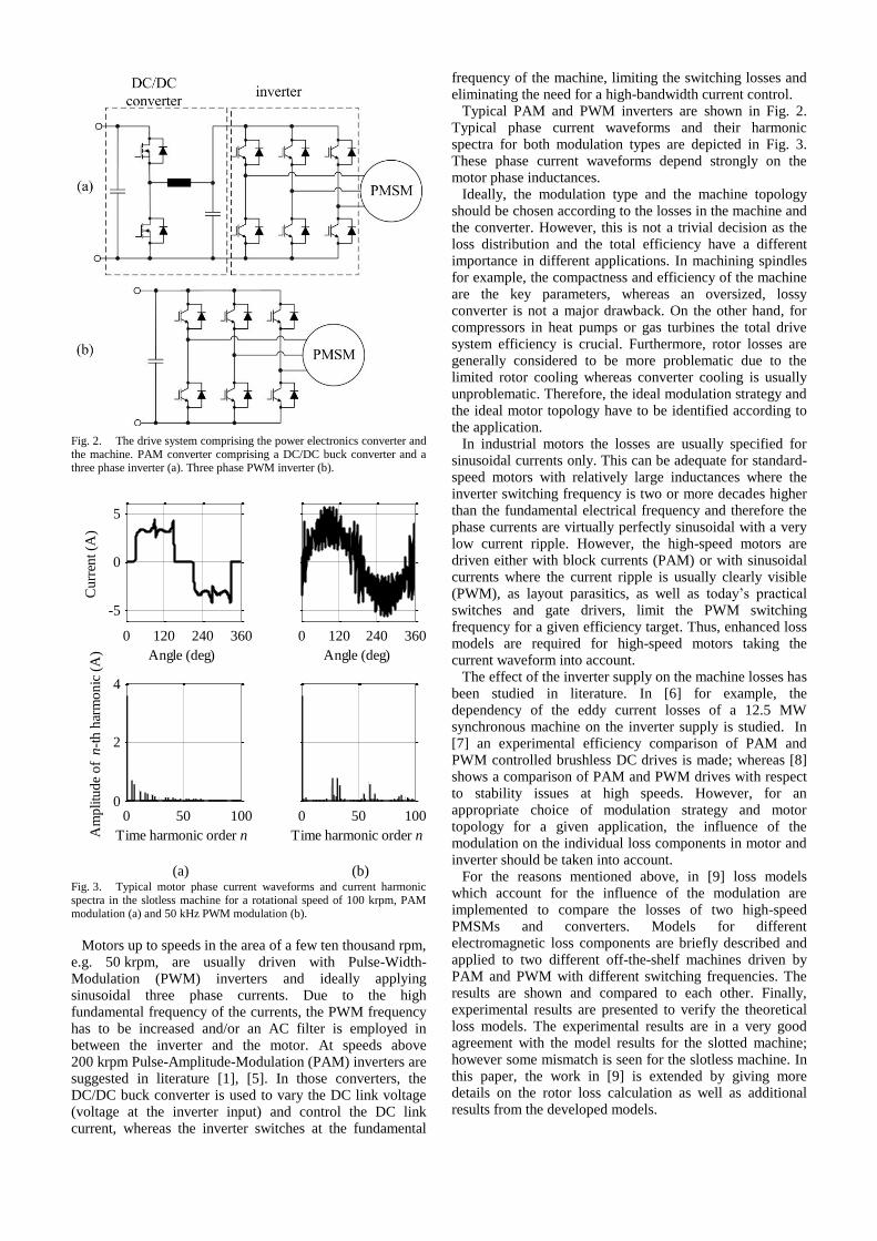
Fig. 2. The drive system comprising the power electronics converter and the machine. PAM converter comprising a DC/DC buck converter and a three phase inverter (a). Three phase PWM inverter (b).
Fig. 3. Typical motor phase current waveforms and current harmonic spectra in the slotless machine for a rotational speed of 100 krpm, PAM modulation (a) and 50 kHz PWM modulation (b).
Motors up to speeds in the area of a few ten thousand rpm,
e.g. 50 krpm, are usually driven with Pulse-Width-Modulation (PWM) inverters and ideally applying sinusoidal three phase currents. Due to the high fundamental frequency of the currents, the PWM frequency has to be increased and/or an AC filter is employed in between the inverter and the motor. At speeds above 200 krpm Pulse-Amplitude-Modulation (PAM) inverters are suggested in literature [1], [5]. In those converters, the DC/DC buck converter is used to vary the DC link voltage (voltage at the inverter input) and control the DC link current, whereas the inverter switches at the fundamental
frequency of the machine, limiting the switching losses and eliminating the need for a high-bandwidth current control.
Typical PAM and PWM inverters are shown in Fig. 2. Typical phase current waveforms and their harmonic spectra for both modulation types are depicted in Fig. 3. These phase current waveforms depend strongly on the motor phase inductances.
Ideally, the modulation type and the machine topology should be chosen according to the losses in the machine and the converter. However, this is not a trivial decision as the loss distribution and the total efficiency have a different importance in different applications. In machining spindles for example, the compactness and efficiency of the machine are the key parameters, whereas an oversized, lossy converter is not a major drawback. On the other hand, for compressors in heat pumps or gas turbines the total drive system efficiency is crucial. Furthermore, rotor losses are generally considered to be more problematic due to the limited rotor cooling whereas converter cooling is usually unproblematic. Therefore, the ideal modulation strategy and the ideal motor topology have to be identified according to the application.
In industrial motors the losses are usually specified for sinusoidal currents only. This can be adequate for standard-speed motors with relatively large inductances where the inverter switching frequency is two or more decades higher than the fundamental electrical frequency and therefore the phase currents are virtually perfectly sinusoidal with a very low current ripple. However, the high-speed motors are driven either with block currents (PAM) or with sinusoidal currents where the current ripple is usually clearly visible (PWM), as layout parasitics, as well as today’s practical switches and gate drivers, limit the PWM switching frequency for a given efficiency target. Thus, enhanced loss models are required for high-speed motors taking the current waveform into account.
The effect of the inverter supply on the machine losses has been studied in literature. In [6] for example, the dependency of the eddy current losses of a 12.5 MW synchronous machine on the inverter supply is studied. In [7] an experimental efficiency comparison of PAM and PWM controlled brushless DC drives is made; whereas [8] shows a comparison of PAM and PWM drives with respect to stability issues at high speeds. However, for an appropriate choice of modulation strategy and motor topology for a given application, the influence of the modulation on the individual loss components in motor and inverter should be taken into account.
For the reasons mentioned above, in [9] loss models which account for the influence of the modulation are implemented to compare the losses of two high-speed PMSMs and converters. Models for different electromagnetic loss components are briefly described and applied to two different off-the-shelf machines driven by PAM and PWM with different switching frequencies. The results are shown and compared to each other. Finally, experimental results are presented to verify the theoretical loss models. The experimental results are in a very good agreement with the model results for the slotted machine; however some mismatch is seen for the slotless machine. In this paper, the work in [9] is extended by giving more details on the rotor loss calculation as well as additional results from the developed models.
0 120 240 360
-5
0
5
Angle (deg)
Cu
rren
t (A
)
0 50 1000
2
4
Time harmonic order nAm
plitu
de
of
n-t
h h
arm
on
ic (
A)
0 120 240 360
Angle (deg)
0 50 100
Time harmonic order n
(a) (b)

III. LOSS MODELS
A. Rotor loss model An analytical model is used for calculating the rotor
losses. The analytical model has the advantage that it can be quickly evaluated for different modulations, rotational speeds and machines. As the skin depth at the occurring frequencies has the same order of magnitude as the rotor diameter, the eddy current reaction field must be considered. As high-speed machines generally have a small number of poles and a highly conductive rotor sleeve, the model should also account for currents in the sleeve and the rotor curvature.
In [10] a rotor loss model based on the 2D solution of the Maxwell equations considering the effects mentioned above is introduced. The stator iron is assumed to be infinitely permeable. An equivalent current sheet is used on the stator bore as the external boundary condition to model the stator windings as equally distributed surface currents on the slot openings. This current sheet can be described as a superposition of combinations of time and space harmonics as in
( )a ( ) cos( )1
( , ) , 1a t a vv
vK t ia a
¥å=
=
where Ka is the surface current density of equivalent current sheet representing one phase of the machine, α is angle of polar coordinates in the stator reference frame, ia is the current of the represented phase, v is the space harmonic order and av is the amplitude of v
th space harmonic of the
equivalent current sheet. As an example, the current sheet of a single coil built into
two slots on opposite sides of the stator is illustrated in Fig. 5. Its Fourier series expansion can be calculated as
( )a4
( ) sin( )21,3,5...
( , ) , 2a
bW ot vRb v sov
K t ip
a å=
=
where bo is the slot opening, W is the number of turns and RS is the stator bore radius.
The equivalent current sheet of a two layer winding with a winding pitch of 1:8 of a 3-phase, 2-pole, 18-slot machine, which applies for the investigated slotted machine is shown in Fig. 4. Symmetric currents are assumed as in
( )ˆ cos( ( ) )1
( ) , 3ph I n tn r nphn
i t w q q¥
+ +å=
=
where iph is the current of a phase, În is the amplitude of the n
th order harmonic of that phase current, ωr is the angular
frequency, n is the time harmonic order, ϴph is the phase shift between single phases and ϴn is the phase difference of n
th harmonic with respect to the fundamental component.
Symmetric currents described in (3) in the equivalent current sheet of Fig. 4 results in
cos( )1
( , ) ,a K n t mnm r nn m
K t w a qa¥ ¥
+ +å å= =- ¥
=
(
3| | ( ) divisible by 32 , , 4)
otherwise0nm
I an m m nK =
ìïïïïíïïïïî
+
where m is the space harmonic order of the current sheet, which is –v for a negative and v for a positive rotating wave and Knm is the amplitude of the surface current density of the equivalent current sheet for the time harmonic order n and space harmonic order m.
The winding of the slotless machine is of the skewed type, and has an asymmetric cross section due its construction
method. However, for simplicity it is assumed to be concentrated on the stator bore surface neglecting its radial thickness and asymmetry. Hence, the Fourier extension of the current sheet of one phase can be obtained using (2) with bo=2πRS/3.
Fig. 4. Equivalent current sheet: current in a slot represented as a
surface current density on the slot opening surface (circles).
Fig. 5. The current sheet representation of a single coil built into two
slots on opposite sides of the stator.
After the current sheets are defined, the diffusion equation in the sleeve and the magnet regions as well as the Laplace's equation in the air gap region are solved and the rotor losses are calculated using Poynting's theorem for each combination of time and space harmonics separately, as described in detail in [10], but with different regions and internal boundary conditions. The inner boundary condition is replaced by the claim for continuity on the rotational axis for the rotor construction with a fully cylindrical magnet. Its finite permeability is also considered for the construction with a rotor hub. The machine phase currents are calculated taking the modulation and frequency dependency of the winding inductance into account, and applied to the rotor loss model to calculate the rotor losses. Room temperature is assumed while reading the resistivity values for the rotor materials from the datasheets due to their low temperature coefficients of electrical resistivity.
B. Core loss model
The empirical method developed by Steinmetz has been widely used for predicting the core losses in inductors, transformers and rotating electrical machines. However, this method is not sufficiently accurate when the excitation is nonsinusoidal (as in inductors used in switched power supplies), or if the flux is not only alternating, but also has a rotating component (as in rotating electrical machines). In literature numerous methods are proposed to take those effects into consideration. In [11] the Steinmetz method is modified to account for nonsinusoidal excitation. In [12] the effects of the rotational flux are also taken into account.
In this work, the method presented in [13] is adopted because it takes both nonsinusoidal and rotating flux effects into account, and it needs only the standard loss coefficients which are generally provided by the manufacturers. The phase currents for PAM and PWM are calculated separately and impressed into the windings of a 2D transient model in the software to calculate the core losses.
α
0aWI b
π
K
0aWI b
0 Sb R
~ ~

C. Copper loss model
The total copper losses in an electrical machine can be
calculated as
( )2
Cu,s Cu,p
Cu
2( ),n,rms 5ˆ
I Fn
P P GH
så ++ =
where PCu,s is the ohmic losses created by the current flowing in the conductor and PCu,p is the proximity effect losses caused by external fields. Those components of the copper losses are calculated for different frequency components of the current where In,rms is the RMS value of
the nth
frequency component of the current, H is the peak
external field strength and σcu is the conductivity of copper. The coefficients F and G depend on the winding configuration and the skin depth, and they are calculated according to [14].
As can be seen in (5), the field strength in the winding
area is needed to calculate the proximity losses. In the
slotless machine topology, this field is the superposition of
the permanent magnet field and the armature field. The
magnitude of the armature field is typically much smaller
than the magnitude of the permanent magnet field; however,
it contains frequency components higher than the
fundamental electrical frequency of the machine; hence it
contributes to the losses, especially at higher frequencies.
Thus, the proximity losses caused by the rotor and armature
fields are calculated separately and superimposed.
The permanent magnet field in the slotless machine is calculated analytically according to [15]. A 2D FE model of the machine is used to calculate the armature field.
In the slotted machine topology, the rotor and armature flux is mostly carried in the iron due to its much higher permeability compared to the windings. Therefore, only the stray field is responsible for the proximity losses. The 1-D model shown in Fig. 6 is used to calculate the stray field. If the field is assumed to have only a y-axis component and the permeability of the iron is assumed to be infinite, the field strength can be calculated as
( )0
61
( ) ( ) ,( )
x
H x J x dxb x
¢ ¢= òr r
where J is the current density.
D. Friction and windage losses
Friction and windage losses are not modeled in this work, as they do not depend on the modulation scheme of the converter.
E. Converter loss model
The power electronics converter consists of only three
bridge legs for PWM operation (Fig. 2a) or of three bridge
legs and an additional DC/DC buck converter for PAM
operation (Fig. 2b). The DC/DC buck converter is modeled
with a constant efficiency of 98.5% as its losses in the
semiconductors and the passives do not depend on the
shape of the phase current, and therefore the machine type.
The inverter stage comprises six IGBTs, and the inverter
losses can be split into switching and conduction losses.
The conduction losses are calculated with the IGBT and
diode forward voltages and on resistances from datasheets
and the according average and RMS currents of the phase
current waveforms. The turn on and turn off switching
energy losses of the IGBTs and diodes have been measured
in a separate setup for a range of current and voltage
operating points. For the switching loss calculation this data
is interpolated at the operating points according to the phase
current waveforms and motor voltages. Finally, the
switching energies are related to a pulse period, i.e.
translated into a power loss by multiplication with the
switching frequency and summed up with the conduction
losses for the total inverter losses. As mentioned above, in
the case of PAM 1.5% of the inverter input power is added
for the total converter losses to account for the buck
converter losses.
In order to calculate the current waveforms for PAM, the
circuit in Fig. 2a is simulated after replacing the DC/DC
buck converter with a constant current source and the
PMSM with inductors and AC voltage sources. The IGBTs
are modeled with ideal switches. For PWM, symmetrical
regular sampling space vector modulation is used, and the
currents are calculated analytically in the frequency domain
which is suitable to be used in the copper and rotor loss
models. For the iron loss model, where a time domain
solution is needed, the inverse Fourier transformation is
used. The DC link voltage is calculated for each machine
and operating point separately, such that the DC link has a
20% voltage reserve over the terminal voltage of the
machine at the investigated operating point. The reason
behind this approach is the fact that, during the design phase
the inverter and the machine voltages can be adjusted to
match each other, and the goal of this work is to find the
optimum modulation and machine combination for a given
operating point rather than the analysis of one drive system
at different operating points.
IV. MODEL RESULTS
A. Investigated machines and converters
The loss models described earlier are applied to a slotted and a slotless machine, both driven with PAM and PWM. Both the slotless and the slotted machines have one pole pair and they are designed for a nominal speed of 200 krpm and a nominal torque of 30 mNm.
The slotless machine has skewed type air gap windings with 54 turns per phase. The stator is made of amorphous iron. The rotor of the slotless machine is made of a one piece diametrically magnetized magnet, contained by a grade 5 titanium sleeve. The outer diameter of the rotor is 12.5 mm.
The slotted machine has two layer windings inserted into 18 slots. The rotor of the slotted machine is similar to that of the slotless machine, with an additional rotor hub made of magnetic steel at its center. The outer diameter of the rotor is 11.5 mm.
The flux linkage, phase inductance and resistances are 5.61 mVs, 65 µH and 0.49 Ω for the slotless machine; 5.94 mVs, 300 µH and 1.14 Ω for the slotted machine. The stators of the two machines can be seen in Fig. 7.
The converter used in this work is the CC-230-3000 from Celeroton. The converter consists of a DC/DC buck converter, connected to the DC side of a 3-phase 6-switch voltage source inverter [15]. The buck converter is bypassed in PWM operation. The inverter switches are International Rectifier IRGP50B60PD1s. This 3 kW converter is considerably oversized considering the power levels (at the considered operating points) of the machines. However, the goal is the validation of the modeling approach, which can be used at the design stage of further

Fig. 6. 1-D model for calculation of the stray field in the slotted
machine. A 2-layer winding is assumed.
drive systems, where the motor and converter power levels
would preferably be closer to each other.
B. Rotor losses
The calculation of the rotor losses for different time and space harmonics of the machine current reveals that the impact of the space harmonics is very small. The rotor losses, for example for PAM and a speed of 100 krpm caused by the fundamental and the higher order space harmonics are 4.29 W and 118 µW for the slotless machine and 6.34 W and 3.88 mW for the slotted machine. The large effective air gap of the machines is considered to be the main reason for these results.
Fig. 8 and Fig. 9 show the rotor losses produced by the time harmonics normalized to the square of the amplitude of the exciting current harmonic for the two machines. It can be seen that the increase of losses flattens for higher order time harmonics. This is due to the eddy current reaction field which prevents the field from entering the conducting region. This effect is significantly stronger for the slotted machine than for the slotless machine. This effect lowers the losses of PWM with respect to PAM as the current harmonics are of a higher order but generally smaller amplitude for PWM. This leads to lower rotor losses at higher PWM frequencies.
The effects of different time and space harmonic combinations can be seen in Fig. 10.
C. Core losses
As described earlier, using the instantaneous core loss calculation method in [13] allows for the comparison of time behaviors of the core losses under different modulation methods. Although the instantaneous core losses look different for PAM and PWM, the average core loss depends only slightly on the modulation. The average core losses under no load for a speed of 100 krpm, PAM and 50 kHz PWM are 674 mW, 735 mW and 1.02 W for the slotless machine and 6.7 W, 8.2 W and 7.15 W for the slotted machine.
D. Copper losses
The windings of both the slotless and the slotted machines considered in this work are made of litz wire, with strand diameters of 71 µm and 170 µm, respectively. Thus, the calculated F coefficient in (5) is practically equal to the DC resistance of the windings up to frequencies around 50 kHz. This means that the first part of (5) does not depend on the modulation type.
The proximity losses are calculated for a typical fundamental frequency of 1.67 kHz (100 krpm) and a switching frequency of 50 kHz. Table 1 shows the different components of the proximity losses. It can be seen that
proximity losses produce a rather small amount of the total losses; however they can become important when the high frequency components of the drive current also have high amplitudes.
E. Loss spectrum
The models for the copper and the rotor losses allow determining the loss spectrum as these models provide a frequency domain solution whereas the iron losses are calculated in the time domain. Fig. 11 and Fig. 12 show the loss spectra of the copper and rotor losses which represent the largest parts of the machine losses. The copper losses are mainly caused by the fundamental component and therefore depend only slightly on modulation. The losses of higher order harmonics are dominated by the rotor losses. For the slotless machine and a switching frequency of 50 kHz PWM produces far more rotor losses than PAM.
Fig. 7. Stators of the slotless (left) and the slotted (right) machines.
Fig. 8. Rotor losses caused by time harmonics for the slotless machine and a rotational speed of 100 krpm.
F. Total drive system losses
The comparison of all the loss components for the slotless machine under PAM and PWM operation are shown in Fig. 13 for a speed of 100 krpm. The iron losses are very small with respect to the total losses, and hardly visible in the plot. This is due to the low loss amorphous core material. Iron losses depend only slightly on the modulation type, since the armature reaction field is much smaller than the permanent magnet field.
10 20 30 40 50 600
2
4
6
8
10
12
14
16
No
rmal
ized
loss
es o
f n
-th
har
mo
nic
(W
A-2
)
Time harmonic order n
Time harmonic order n

Fig. 9. Rotor losses caused by time harmonics for the slotted machine and a rotational speed of 100 krpm.
Fig. 10. The effects of different time (n) and space (m) harmonics on the rotor losses. Rotor eddy currents are plotted. (red) into the direction of the page, (blue) out of the direction of the page.
TABLE 1
PROXIMITY LOSS COMPONENTS
Slotless machine Slotted machine
Rotor flux (1.67 kHz) 453.46 mW Armature reaction (1.67 kHz) 55.195 µW/A2 Armature reaction (50 kHz) 49.674 mW/A2
Stray field (1.67 kHz) 191.46 µW/A2 Stray field (50 kHz) 172.18 mW/A2
0 20 40 60 80 1000
5
10
15
20
Time harmonic order n
Lo
sses
of
n-t
h h
arm
onic
(W
)
Copper
Rotor
Fig. 11. Loss harmonic spectrum for PWM, a switching frequency of 50 kHz, the slotted machine and a rotational speed of 100 krpm.
0 20 40 60 80 1000
1
2
3
4
5
6
7
8
Time harmonic order n
Lo
sses
of
n-t
h h
arm
onic
(W
)
Copper
Rotor
Fig. 12. Loss harmonic spectrum for PWM, a switching frequency of
50 kHz, the slotless machine and a rotational speed of 100 krpm.
The copper losses make a large contribution to the losses but also show a weak dependence on modulation. This is due to the fact that neither skin nor proximity effect losses have a significant effect at the frequencies occurring. The fundamental component of the current is mainly responsible for the copper losses, and it is kept the same for all modulations in order to maintain the same torque.
It is mainly the rotor losses out of the machine losses which depend on the modulation. The amplitude of the current ripple decreases but its frequency increases with increasing PWM frequency. One could expect that this would lead to constant rotor losses, with these two effects cancelling each other out. However, the eddy current reaction prevents the armature reaction field’s penetration into the entire rotor. This results in decreasing rotor losses with increasing PWM frequencies.
The PWM frequency for the slotless machine needs to be increased beyond 200 kHz to achieve lower machine losses than for PAM, at the speed of 100 krpm.
While the machine losses decrease for higher PWM frequencies, the converter losses increase due to increasing switching losses. With respect to the total losses, the optimum PWM frequency is 90 kHz but the total losses in this case are still more than twice as high as for PAM. The machine losses for the slotless machine are plotted for a speed range between 50 krpm to 200 krpm in Fig. 14.
Results of the loss models for the slotted machine are shown in Fig. 15 for a speed of 100 krpm. Iron and copper losses for the slotted machine are larger compared to the slotless machine. Similar to the slotless machine, iron and copper losses depend to a very small extent on the modulation type whereas converter and rotor losses change significantly with modulation. The machine losses for a PWM frequency greater than 35 kHz are smaller than for PAM. The machine losses for a switching frequency of 50 kHz are 5 W less compared to PAM whereas the converter losses are higher by 7.9 W.
The machine losses for the slotted machine are plotted for a speed range between 50 krpm to 200 krpm in Fig. 16.
10 20 30 40 50 600
5
10
15
20
Norm
aliz
ed loss
es o
f n
-th h
arm
onic
(W
A-2
)
Time harmonic order n
Time harmonic order n
m=1, n=5 m=1, n=95 m=5, n=1

V. EXPERIMENTAL RESULTS AND DISCUSSION
A. Measurement results
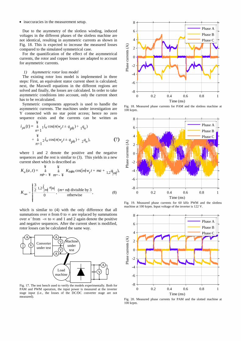
The test setup in Fig. 17 is built to verify the loss models by experiments. The converter under test drives the machine under test at a constant speed. The load machine dissipates the mechanical power in a load resistor connected through a passive rectifier. As the load power and the mechanical losses are constant for a given speed, the influence of a different modulation can be easily measured by measuring the input power to the machine and the converter. As the losses of the DC/DC buck converter are assumed to be independent of the machine current shape, its losses are not measured. Therefore, both for PAM and PWM, the input power is measured at the input of the inverter stage.
Fig. 18 to Fig. 21 show measured currents for the slotless and the slotted machine, under PAM and 60 kHz PWM. The machines are operating at 100 krpm and loaded with 30 mNm. In Fig. 22, the measured and calculated difference of the machine losses under PWM and PAM are given for different PWM frequencies. The comparison of calculated and measured inverter losses are shown in Fig. 23 for the slotless machine and in Fig. 24 for the slotted machine.
Fig. 13. Comparison of model results for the slotless machine and a rotational speed of 100 krpm. For PAM, the losses of the DC/DC buck converter whose efficiency is assumed constant at 98.5% are included in the converter losses.
B. Discussion
As seen in Fig. 23 and Fig. 24, the models for the inverter losses are consistent with the measurement results. The mismatch of PAM inverter losses is within the expected accuracy of ±6 W for that particular measurement setup (a DC offset of %1 on the probes may lead to an error of ±6 W at the inverter input power measurement). Fig. 22 shows that the loss models match the measurements very well for the slotted machine as well.
However, a considerable mismatch is seen in Fig. 22 between the model results and the measurement results for the slotless machine, meaning the simulated PAM losses are too low compared to the measurements and/or the simulated PWM losses are too high compared to the measurements. Possible reasons for this mismatch are:
Fig. 14. Losses of the slotless machine over rotational speed.
Fig. 15. Comparison of model results for the slotted machine and a
rotational speed of 100 krpm. For PAM, the losses of the DC/DC buck converter whose efficiency is assumed constant at 98.5% are included in the converter losses.
50 100 150 2000
20
40
60
80
100
Speed (krpm)
Mac
hin
e lo
sses
(W
)
PAM
PWM 25 kHz
PWM 50 kHz
PWM 75 kHz
PWM 100 kHz
Fig. 16. Losses of the slotted machine over rotational speed.
asymmetrical phase currents,
skew of the winding which is not modeled accurately,
3D eddy current effects,
PAM0
10
20
30
40
50
60
70
Loss
es (
W)
50 100 150 200
PWM, Switching frequency (kHz)
IronCopper
Rotor
Converter
50 100 150 2000
50
100
150
Speed (krpm)
Mac
hin
e lo
sses
(W
)
PAM
PWM 50 kHz
PWM 100 kHz
PWM 150 kHz
PWM 200 kHz
PAM0
10
20
30
40
50
60
Loss
es (
W)
20 40 60 80 100
PWM, Switching frequency (kHz)
Iron
Copper
Rotor
Converter
inaccuracies in the measurement setup.
Due to the asymmetry of the slotless winding, induced voltages in the different phases of the slotless machine are not identical, resulting in asymmetric currents as shown in Fig. 18. This is expected to increase the measured losses compared to the simulated symmetrical case.
For the quantification of the effect of the asymmetrical currents, the rotor and copper losses are adapted to account for asymmetric currents.
1) Asymmetric rotor loss model
The existing rotor loss model is implemented in three steps: First, an equivalent stator current sheet is calculated; next, the Maxwell equations in the different regions are solved and finally, the losses are calculated. In order to take asymmetric conditions into account, only the current sheet has to be recalculated.
Symmetric components approach is used to handle the asymmetric currents. The machines under investigation are Y connected with no star point access; hence no zero sequence exists and the currents can be written as
( )
ˆ1 1
ˆ2 2
cos( ( ) )1
cos( ( ) )1
( )
, 7
ph In n
In n
n tr ph
n
n tr ph
n
i t w q q
w q q
¥± +å
=
¥+ ± +å
=
=
where 1 and 2 denote the positive and the negative sequences and the rest is similar to (3). This yields in a new current sheet which is described as
1,2cos( )( , ) ,a n
nK t mn m r
n mK t w a qa ¢
¢
¥ ¥+ +å å ¢
¢= - ¥ = - ¥=
1,2
(
3 ˆ( ) divisible by 32
, , 8)otherwise0n m
a mnI
m nK
¢=
ìïïï ¢ïïíïïïïïî
¢+
which is similar to (4) with the only difference that all summations over n from 0 to ∞ are replaced by summations over n’ from -∞ to ∞ and 1 and 2 again denote the positive and negative sequences. After the current sheet is modified, rotor losses can be calculated the same way.
V
A
A
VV
V
A
A
DU
T
Machine
under
test
Load
machine
Converter
under test
Fig. 17. The test bench used to verify the models experimentally. Both for PAM and PWM operation, the input power is measured at the inverter stage input (i.e., the losses of the DC/DC converter stage are not measured).
0 0.2 0.4 0.6 0.8 1
-8
-6
-4
-2
0
2
4
6
8
Time (ms)
Ph
ase
curr
ents
(A
)
Phase A
Phase B
Phase C
Fig. 18. Measured phase currents for PAM and the slotless machine at 100 krpm.
0 0.2 0.4 0.6 0.8 1
-8
-6
-4
-2
0
2
4
6
8
Time (ms)
Ph
ase
curr
ents
(A
)
Phase A
Phase B
Phase C
Fig. 19. Measured phase currents for 60 kHz PWM and the slotless machine at 100 krpm. Input voltage of the inverter is 122 V.
0 0.2 0.4 0.6 0.8 1
-8
-6
-4
-2
0
2
4
6
8
Time (ms)
Ph
ase
curr
ents
(A
)
Phase A
Phase B
Phase C
Fig. 20. Measured phase currents for PAM and the slotted machine at 100 krpm.

0 0.2 0.4 0.6 0.8 1
-8
-6
-4
-2
0
2
4
6
8
Time (ms)
Ph
ase
curr
ents
(A
)
Phase A
Phase B
Phase C
Fig. 21. Measured phase currents for 50 kHz PWM and the slotted machine at 100 krpm. Input voltage of the inverter is 130 V.
2) Asymmetric copper loss model
Copper losses are calculated in (5) as the sum of PCu,s which is the ohmic losses created by the current flowing in the conductor itself and PCu,p which is the proximity effect losses caused by external fields. PCu,s can easily be calculated also for asymmetrical currents using the symmetrical components approach as shown above. For PCu,p, the effect of asymmetrical currents are taken into account by dividing the armature field into two parts, excited by positive and negative sequences of the asymmetric currents, and calculating them separately using FE analysis. 3) Results
The adapted copper and rotor loss models revealed that asymmetric currents in the slotless windings are responsible only for a small amount (around 1 W) of the considered mismatch. For this reason, this consideration is not analyzed any further.
3D effects will be analyzed in the future work, as it is well known that 2D models may give very inaccurate results when rotor eddy currents are considered on some geometries. Due to the lack of the end resistances, eddy current losses calculated by 2D models tend to be higher than those calculated by 3D models. Considering the high rotor losses calculated for the slotless machine under PWM by 2D models, the 3D effects are considered to be a probable reason for the mismatch. This will be analyzed in the course of future research.
VI. CONCLUSION
For variable speed drives, the interaction of the motor and the converter is becoming increasingly important, especially at higher rotational speeds.
In this work, individual models for calculating the rotor, copper, stator core and inverter losses are given. These models are developed considering two typical high-speed PMSM topologies (slotted and slotless machines) and two typical converter types (PWM and PAM). The models are applied to two off-the-shelf machines and an off-the-shelf converter that can operate both by PAM and PWM. Table 2 summarizes the results.
The results show that for the slotless machine used in this work PAM gives higher efficiency, both in the machine and the converter, for speeds between 50 krpm and 200 krpm.
However, the PAM requires an additional DC/DC buck converter, comprising at least two switches for bi-directional operation, a DC link inductor and a DC link capacitor, resulting in higher effort in design and higher volume. The overall drive system losses for the slotted machine under PAM and PWM are closer to each other, with PAM still producing less overall losses at 100 krpm.
TABLE 2
MACHINE AND CONVERTER LOSSES AND OVERALL EFFICIENCIES AT THE SPEED OF 100 KRPM AND OUTPUT POWER OF 314 W
Machine
Losses (W) Converter
Losses (W) Overall
Efficiency (%)
Slo
tles
s
PAM 14.1 10.8 92.1
PWM
50 kHz 43.7 20.9 79.4
PWM
100 kHz 23.7 31.7 82.4
Slo
tted
PAM 35.9 10.6 85.2
PWM 50 kHz
30.9 18.5 84.3
PWM 100 kHz
28.1 30.8 81.2
An important outcome is that by using PWM with an appropriate switching frequency, the losses can be moved from the rotor to the inverter, with the expense of slightly decreasing overall efficiency. This result can be used in applications where the rotor losses are more important than the overall efficiency, such as spindle applications. For that reason, in the Appendix the analysis of converters with higher switching frequencies are discussed briefly.
Finally, a test setup is built to measure the losses for different machines, under different modulations. Experimental results verify the validity of the models.
Future work includes the further improvement of the loss models. For example, 3D effects (end effects) can be taken into account to improve the accuracy of the models. At a second step, both the geometry and the materials of the machines can be optimized using the models introduced in this paper. Furthermore, both modulation schemes can be further optimized, e.g. certain harmonic elimination methods can be utilized for minimizing certain loss components such as the rotor losses.
VII. ACKNOWLEDGMENTS
The authors gratefully acknowledge the support of ATE Antriebstechnik und Entwicklungs GmbH, who provided the slotted machine used in this work and André Schaubhut who enhanced the loss models.
VIII. APPENDIX
In this paper experimental results are given for a 3 kW converter, which is over-dimensioned for the machine operating point (314 W). Furthermore, the reference switching loss measurements can be source of errors and they cannot be carried out during the design phase of a converter. Therefore, here a Spice model based loss calculation is given for the semiconductor switches. Simulations are done for fictitious (not built) converters which are designed with lower power ratings, using 200 V switches. As it is shown that higher PWM frequencies can reduce the motor losses, GaN switches become interesting and they are analyzed first. However, as GaN switches are not widely available today, silicon MOSFET switches with

similar blocking voltage and continuous current ratings are also analyzed for the sake of completeness.
0 20 40 60 80 100 120
-10
0
10
20
30
40
50
PWM frequency fPW M
(kHz)
Mac
hin
e lo
sses
(W
) fo
r P
WM
, d
iffe
ren
ce t
o P
AM
Slotless, measurement
Slotless, model
Slotted, measurement
Slotted, model
Fig. 22. Deviation of measured as well as modeled machine losses for both machines and a rotational speed of 100 krpm for PWM with respect to PAM.
60 80 100 120
PWM, switching frequency (kHz)
Measurement
Model
PAM0
5
10
15
20
25
30
35
Inver
ter
loss
es (
W)
Fig. 23. Calculated and measured inverter losses for the slotless machine at 100 krpm.
20 40 60 80 100
PWM, switching frequency (kHz)
Measurement
Model
PAM0
5
10
15
20
25
30
35
Inver
ter
Loss
es (
W)
Fig. 24. Calculated and measured inverter losses for the slotted machine at 100 krpm.
EPC2010, the 200 V, 11 A device from Efficient Power Conversion Corporation is chosen as the GaN switch. BSC12DN20NS3 from Infineon is chosen as the silicon switch as it has the same blocking voltage and continuous current rating as its GaN counterpart.
LTSpice from Linear Technology is used to build Spice models of a PWM and PAM converter. A fictitious machine is presented by phase inductances of 45 µH, phase resistances of 0.5 Ω, and sinusoidal voltage sources (58V, 1.66 kHz) representing the back EMF at 100 krpm.
The accuracy of the approach for estimating the converter losses depends very strictly on the accuracy of the Spice models. For that reason, firstly the Spice models provided by the vendors were tested. Small virtual test circuits were implemented in LTSpice environment to check if the device properties such as the on-state resistance, the on-state voltage drop of the body diode, and the non-linear behavior of the output capacitance COSS match the datasheet values.
Each bridge leg is modeled taking parasitic inductances into account as shown in Fig. 25. The values of those stray elements are estimated based on an existing practical design of a 250 W buck-boost converter layout. A constant dead time of 50 ns is assumed in all cases. The gate voltage is 5 V for the GaN and 10 V for the Si switches. The rise and fall times of the gate drivers are modeled using an RC network whose time constant is 2 ns for the GaN and 4 ns for silicon switches.
The input voltage, both for PWM and PAM is set to 150 V. For PAM, the DC/DC converter stage bridge leg is modeled identical to the bridge legs of the inverter stage. The switching frequency of the DC/DC converter is set to 100 kHz both for the GaN and the silicon cases.
The inductor in the PAM converter is assumed to have litz wires and a toroid core without gap, made of iron powder 18 from Micrometals. The inductor is optimized for minimum volume according to [16], and it has an overall volume of 8 cm
3 and its total losses (including core, copper
and proximity effect losses) are calculated to be 3.8 W for an inductor current whose average value is 3.15 A with a ripple of 3.2 A (peak-to-peak).
The output power of the machine, which is modeled as the power fed into the voltage sources representing the back EMF, is adjusted to be 300 W in all cases. Fig. 26 shows the losses of PAM and PWM converter for both silicon and GaN switches. Fig. 27 shows the distribution of losses in the PAM converters.
The junction-to-ambient thermal resistance for both the GaN and silicon switches is around 50
oC/W when no heat
sink is used. This means, without a heat sink, 2 W of losses should not be exceeded by any individual switch (12 W total losses) to ensure a safe junction temperature (less than 125
oC), considering 25
oC ambient temperature.
For the PWM converter, the losses are equally distributed to all the six switches. As only the losses in the switches are considered here (no additional losses such as the power consumption of the auxiliary power supply); one can conclude that 12 W of total losses set the theoretical thermal limit of these converters when no additional cooling effort is considered.
For the PAM converter with GaN switches, the switch with the highest losses is the upper switch of the DC/DC converter with 1.04 W losses. The lower switch and the individual inverter switches produce 130 mW and 90 mW respectively. For the PAM converter with silicon switches, the losses of the upper DC/DC converter switch are close to the limit with 1.9 W. The lower switch and the individual

inverter switches produce 400 mW and 390 mW respectively.
This analysis shows that using a converter of appropriate power rating with a carefully designed layout and some additional cooling effort, the PWM frequencies can be increased in order to limit the rotor losses of the high-speed machines.
Fig. 25. The bridge leg comprising switches, stray inductances, gate drivers and (external) gate resistors. The values of the parameters are given on the right hand side for GaN and silicon switches. A sufficiently big DC link capacitor CDC is assumed and it is modelled with a constant voltage source. The parasitic inductance of the capacitor is neglected.
IX. REFERENCES
[1] C. Zwyssig, J. W. Kolar, and S. D. Round, "Megaspeed Drive Systems: Pushing Beyond 1 Million r/min," IEEE/ASME Trans. on Mech., vol. 14, no. 5, pp. 564 574, Oct. 2009.
[2] M. A. Rahman, A. Chiba, and T. Fukao, "Super high speed electrical machines—Summary," Proc. of IEEE Power Eng. Soc. General Meeting, vol. 2, pp. 1272–1275, Denver, USA, Jun. 2004.
[3] A. Binder and T. Schneider, "High speed inverter fed AC drives," Proc. of Int. Aegean Conf. Electr. Mach. Power Electron., Bodrum, Turkey, Sep. 2007.
[4] A. Looser, T. Baumgartner, C. Zwyssig, and J. W. Kolar, "Analysis and measurement of 3D torque and forces for permanent magnet motors with slotless windings," Proc. of. IEEE Energy Conv. Cong.
and Exp. (ECCE USA), pp. 3792 3797, Atlanta, USA, Sep. 2010. [5] K. Taniguchi and A. Okumura, “A PAM inverter system for vector
control of induction motor,“ Proc. of Power Conv. Conf (PCC)., pp. 478 483, Yokohama, Japan, 1993.
[6] P. Rasilo, and A. Arkkio, A, "Modeling the effect of inverter supply on eddy current losses in synchronous machines," Proc. of Int. Symp. on Power Elec. Elec. Drives Automation and Motion (SPEEDAM), pp. 861 865, Pisa, Italy, Jun. 2010.
[7] L. Yen Shin, L. Ko Yen, T. Jing Hong, C. Yen Chang, and H. Tse Liang, "Efficiency comparison of PWM controlled and PAM controlled sensorless BLDCM drives for refrigerator applications," Conf. Rec. of the 42nd IEEE IAS Ann. Meeting Ind. Appl. Conf., pp. 268 273, New Orleans, USA, Sep. 2007.
[8] K. H. Kim and M. J. Youn, “Performance comparison of PWM inverter and variable DC link inverter schemes for high speed sensorless control of BLDC motor,“ Electronics Letters, Vol. 38, pp. 1294 1295, 2002.
[9] L. Schwager, A. Tüysüz, C. Zwyssig, and J. W. Kolar “"Modeling and comparison of machine and converter losses for PWM and PAM in high speed drives,” Proc. IEEE 20th Int. Conf. Electr. Mach. (ICEM), pp. 2441 2447, Marseilles, France, Sep. 2012.
[10] Z.Q. Zhu, K. Ng, N. Schofield and D. Howe, "Improved analytical modelling of rotor eddy current loss in brushless machines equipped with surface mounted permanent magnets," IEE Proc. Electr. Power Appl., Vol. 151, No. 6, Nov. 2004
[11] J. Reinert, A. Brockmeyer, and R.W. De Doncker, "Calculation of losses in ferro and ferrimagnetic materials based on the modified Steinmetz equation," IEEE Trans. on Ind. Appl., vol.37, no.4, pp.1055 1061, Jul. Aug. 2001.
[12] L. Ma, M. Sanada, S. Morimoto, and Y. Takeda, "Iron loss prediction considering the rotational field and flux density harmonics in IPMSM and SynRM," IEE Proc. Electric Power Appl., vol. 150, no. 6, pp. 747 751, Nov. 2003.
[13] D. Lin, P. Zhou, W. N. Fu, Z. Badics, and Z. J. Cendes, " A dynamic core loss model for soft ferromagnetic and power ferrite materials in
transient finite element analysis," IEEE Trans. on Magn., vol.40, no.2, pp. 1318 1321, Mar. 2004.
[14] J. A. Ferreira, Electromagnetic modeling of power electronic converters. Norwell, USA: Kluwert Academic Publishers, 1989.
[15] C. Zwyssig. An ultra-high-speed electrical drive system. PhD thesis, ETH Zurich, 2008.
[16] J. Mühlethaler, H. Uemura, J. W. Kolar, “Optimal Design of EMI Filters for Single-Phase Boost PFC Circuits”, Proc. of the 38th Ann. Conf. of the IEEE Ind. Electr. Soc. (IECON), Montreal, Canada, Oct. 2012.
100 200 300 400 500
PWM, switching frequency (kHz)
GaN
Silicon
PAM
0
5
10
15
20
Inver
ter
Loss
es (
W) Limit
Fig. 26. Losses for PAM and PWM converters, both with GaN and silicon switches. The output power is 300 W. The DC/DC converter in PAM converter is switching at 100 kHz. For PWM, 12 W is the thermal limit for natural air cooling without heat sinks on the switches.
GaN Silicon
0
2
4
6
8
10
Lo
sses
(W
)
Inductor
DC/DC conv. switches
Inverter switches
Fig. 27. Distribution of PAM converter losses, both for GaN and silicon switches. The output power is 300 W. The DC/DC converter is switching at 100 kHz. Inductor losses include copper and core losses.
X. BIOGRAPHIES
Lukas Schwager received the M.Sc.
degree in electrical engineering from the Swiss Federal Institute of Technology (ETH) Zurich, Zurich, Switzerland, in 2011. During his studies, he focused on power electronics, electrical machines and control systems and did his master thesis at Celeroton, Zurich, Switzerland, an ETH Zurich spinoff company in the area of high-speed electrical drive systems.
He has been working as a R&D engineer for Power Conversion in ABB Discrete
Automation and Motion, Switzerland since January 2012.
LDH
LSH
LGRG
LDL
LSL
LGRG
uGH
uGL
CDC
GaN Si
uGH 0-5 V 0-10 V
uGL 0-5 V 0-10 V
Dead time 50 ns
LDH 500 pH
LSH 100 pH
LDL 100 pH
LSL 500 pH
RG 5 W
LG 1 n
Arda Tüysüz (S'10) received his B.Sc. degree in Electrical Engineering from Istanbul Technical University in Turkey in 2006 and M. Sc. degree from RWTH Aachen
University in Germany in 2009. In his M.Sc. thesis he worked on the full
speed range self-sensing of ultra-high-speed electrical machines. Since June 2009, he is with the Power Electronic Systems Laboratory of Swiss Federal Institute of Technology (ETH) Zurich as a Ph.D. student. His Ph.D. research focuses on novel electrical machine
topologies for high speed drives and self-sensing control of high speed electrical machines.
Christof Zwyssig (M’10) received the M.Sc. and Ph.D. degrees in electrical engineering from the Swiss Federal Institute of Technology Zurich, Switzerland, in 2004 and 2008, respectively. He studied power electronics, machines, and magnetic bearings and was engaged in research on high-speed electrical drive systems and their power electronics. Since January 2009, he has been
with Celeroton AG, Zurich, an ETH Zurich spinoff company in the area of high-speed electrical drive systems, of which he is a
cofounder.
Johann W. Kolar (M'89-SM'04-F'10) received his M.Sc. and Ph.D. degree (summa cum laude / promotio sub auspiciis praesidentis rei publicae) from the University of Technology Vienna, Austria. He has proposed numerous novel PWM converter topologies, and modulation and control concepts, e.g., the VIENNA Rectifier, the SWISS Rectifier, and the Sparse Matrix Converter. Dr. Kolar has published over 550 scientific papers in international journals and conference proceedings and has filed more
than 110 patents. He was appointed Professor and Head of the Power Electronic Systems Laboratory at the Swiss Federal Institute of
Technology (ETH) Zurich on Feb. 1, 2001. The focus of his current research is on ultra-compact/efficient AC-AC
and AC-DC converter topologies employing latest power semiconductor technology (SiC or GaN), Solid-State Transformers for Smart Microgrid Systems, ultra-high speed and bearingless motors, and multi-domain/scale modeling and multi-objective optimization.
Dr. Kolar is a Fellow of the IEEE and a Member of the IEEJ and of International Steering Committees and Technical Program Committees of international conferences in the field. He received numerous Conference and IEEE Transactions Best Paper Awards and serves as an Associate Editor of the IEEE Transactions on Power Electronics since 2001. Since 2002 he also a member of the Editorial Advisory Board of the IEEJ Transactions on Electrical and Electronic Engineering.