modeling and analysis of boost converter in
TRANSCRIPT
Revue des Energies Renouvelables Vol. 21 N°4 (2018) 635 - 649
635
Modeling and analysis of boost converter in
small-signals applied to the wind energy conversion
system using Matlab/Simulink
N. Nisso 1, D. Raïdandi 1,2, N. Djongyang 1 and F.D. Menga 1,3
1 Department of Renewable Energy, National Advanced School of Engineering of Maroua
University of Maroua, Cameroon 2 Department of Mechanical Engineering, National Advanced School of
Engineering of Yaoundé, University of Yaoundé I, Cameroon 3 National Committee for Technology Development
Ministry of Scientific Research and Innovation, Yaoundé, Cameroon
(reçu le 21 Novembre 2018 - accepté le 20 Décembre 2018)
Abstract - The problem of stabilizing a boost converter in small-signal situations using
linear control laws is derived by the means of oriented circuit procedure. After
establishing a small-signal circuit model for the boost regulator including state-feedback,
conditions for the stability of circuit are studied. Thereafter, a linear analysis is performed
in order to design the desired dynamics and robust behavior of the boost converter. The
linear analysis assumed shows that only a state feedback gain matrix is necessary,
provided that the coordinates of the equilibrium point are known. This operation is done
by using the root locus methodto choose the eigenvalue of this gain vector. It aims at
presenting how boost converter averaged behavior can be tailored by means of feedback
control structures. Various control structures with different design methods have become
classical in control systems theory with a similar degree of efficiency. It is generally
assumed that the obtained control input is applied to boost converter by using pulse-width
modulation. Performance of the proposed pole placement method is evaluated by
Simpower/Matlab simulation at the equilibrium operating points chosen. To verify a
feasibility of the proposed method, set parameters of system is implemented. The control
scheme is verified through Matlab simulation, which is present to verify the performance
of proposed method and simulation results validate the analytical predictions. The circuit
studied is an element of the wind energy conversion system (WECS).
Résumé - La stabilisation de tension à l’aide d’un convertisseur Boost par l’utilisation des
lois de commande linéaire est déduite par une procédure du circuit orienté. Après avoir
établi le modèle équivalent du circuit Boost et du retour d’état, les conditions de stabilité
du circuit sont élaborées. Ensuite, une analyse linéaire est effectuée afin de se pencher sur
le comportement dynamique et robuste du circuit. L'analyse linéaire montre que seule une
matrice gain de retour d'état est nécessaire, à condition que les coordonnées du point
d'équilibre soient connues. Pour cela la méthode des lieux de racine est appliquée pour
conduire au choix de la valeur propre de ce vecteur gain. L’objectif est de montrer
comment le comportement moyenné du convertisseur Boost peut être adapté au moyen de
structures de contrôle à rétroaction. Diverses structures de contrôle avec différentes
méthodes de conception sont devenues classiques dans l’étude des systèmes de contrôle
avec un degré d'efficacité similaire. Nous admettons que l'entrée de commande obtenue est
appliquée au convertisseur Boost en utilisant une modulation de largeur d'impulsion
(MLI). Les performances de la méthode de placement de pôles proposée sont évaluées par
simulation aux points de fonctionnement d’équilibre choisis. Pour vérifier la faisabilité de
la méthode proposée, un ensemble de paramètres définis du système est implémenté. Le
schéma de contrôle est vérifié à l’aide d’une simulation sous Matlab/SimPowerSystems,
pour confirmer les performances de la méthode proposée et de valider les résultats des

N. Nisso et al.
636
prévisions analytiques. Le circuit étudié est un élément du système de conversion de
l'énergie éolienne (SCEE).
Keywords: Pole placement - Boost converters - Small-signal stability - Gain vector -
WECS.
1. INTRODUCTION
The basic operation of the feedback loop [1, 2] using boost converter [3, 4] consists
to compare the output variable with a reference input to generate an error signal, which,
after being appropriately filtered and amplified, results in a continuous control signal.
This signal is eventually transformed by means of PWM defining the switch duty cycle.
The main difficulties in the analysis of boost converter are due to the nonlinear
nature of system. If there are no constraints on amplitude or frequency of perturbations
in input voltage, load or external reference, we can always simulate the state equations
describing the boost converter dynamic behavior, but this simulation requires a high
computation time and does not provide enough information to synthesize the control
loop.
Finding the exact analytical solution of the state equations is also possible, although
the resulting formulation cannot be easily applied. These obstacles have oriented this
work in this field toward establishing, with some assumptions, boost converter models
that can be analytically exploited or specifically oriented to numerical simulation with
small computation times.
The boost converter dynamic behavior [5]can be described by means of linear model
if the amplitude of the disturbance is significantly smaller than the steady-state value of
the state vector.
Linear continuous models are very widespread among designers because classical
linear-feedback theory can be easily used for stability analysis and design of feedback
compensation system. However, it is well known that the validity of linear models is
constrained to a small area around the steady-state operation point.
These disadvantages have led some authors to explore nonlinear techniques in order
to undertake the control loop synthesis. The use of these techniques is justified by the
bilinear nature of the boost converter dynamic behavior and by the limitation of the duty
cycle to remain in the interval [0, 1].
The utilization of linearized control to guarantee global stability in the boost
converter was proposed in using Lyapunov functions [6]. Similarly, global stability is
ensured in [7] through a Lyapunov-based control design which provides the feedback
gain matrix through an iterative procedure.
Limits between stable and unstable areas for different values of parameters are
studied in [8] through numerical simulation. A modified small-signal model is used in
[9] to predict the large signal behavior boost converter operating under pulsed load.
The stability graphs are developed in [10] to estimate the values of input voltage and
load resistance leading to a stable design under large-signal operation. The boundaries of
the feedback gains that define the region inside which global stability is ensured.
In [11] the boundaries of the feedback gains that define the region inside which
global stability is acquired using a nonlinear discrete model of the boost converter. A
control technique is developed based on the expression of the saltation matrix to control
nonlinear behaviors in a boost converter [12]. The boost converter in [13] has been used
to achieve the maximum power output of the wind energy by the segmented regulation
by applying the two-voltage stage topology. The research in [14] reveals the robustness

Modeling and analysis of boost converter in small-signals applied to the wind...
637
and the dynamical performances of a boost converter applied on electric vehicle by
using the fuzzy sliding mode technique.
The regulation of the output voltage of a boost converter when the duty cycle is
subjected to the saturation has been addressed in [15]. The controller designed exploited
losses due to parasitic resistances of passive components. The foraging behavior of a
colony of honey bees is meticulously studied and therefore an optimization algorithm is
designed to control a boos converter [16]. A small signal model of a boost converter to
evaluate the accuracy of redesign approaches and direct digital designs, in term of output
voltage transients is treated in [17].
Contrary to our analysis, a cascade output voltage control scheme without the use of
any boost converter parameter is found in [18]. Some of the papers propose nonlinear
control laws of boost converter as fuzzy-PID control [19]. Some papers deal with pole
compensation to synthesize the PI controllers [20] but not to study the regulation of the
output of boost converter.
The papers cited previously do not use the technique of pole placement not only to
study the stability of the boost converters but also and especially for the regulation of the
output voltage. The aim of this paper is to present a new method based on a pole
placement, to analysize the stability of the boost converter in small signals case.
Knowing that the maximum output voltage, it is required that the output voltage tracks –
with zero steady-state error – the desired reference.
Global stability is analyzed by studying the small-signal linearized model of the
boost converter, while meeting a set of imposed performance requirements. Pole
placement method is useful for conveniently place the closed-loop eigenvalues when
full-state feedback information is available. The root locus method will provide a
powerful tool for deriving controllers that ensure robust closed-loop behavior [21].
In Section 2, the equivalent device of a boost converter is reviewed. The small-signal
stability by means of linear feedback is analyzed. The boost converter model, based on
physical description by differential equations and on the classical assumption of perfect
switches, is described.
This model succeeds in capturing the time-varying nature of the device; it will be
used directly for simulation purpose by employing a pole placement control laws design.
The state-space averaged model for small-signal behavior of the boost converter is
studied and its limitations are assessed all this in section 3. Numerical simulation results
are shown in Section 4. Finally, conclusion and references are presented in section 5 and
section 6 respectively.
2. MODELING OF LINEAR BOOST CONVERTER
2.1 Basic modeling
Figure 1 shows the boost converter analyzed in this paper, that is assumed to operate
in continuous conduction mode [22]. cV is the output voltage, E is the line voltage and
Si is the load disturbance. The output voltage must be kept at a known value CrefV . The
boost converter is connected to a load modeled as a linear resistor R .
The capacitance of the capacitor and the inductance of the inductor are represented,
respectively, by C and L . Their equivalent series resistances, Cr and Lr , are
considered sufficiently small to be not considered. Therefore, the measurable states of
the boost converter are the inductor current Li and the capacitor voltage c [23].

N. Nisso et al.
638
The boost converter can takes two configurations, as shown in figure 2: cases (a) and
(b) correspond to switch SW being turned ON and turned OFF respectively.
The boost converter is driven by a binary signal )t(u , called the switching function
[24]. A modulating signal have to be compared with a sawtooth voltage waveform signal
to generate the gate-driving signals, as shown in figure 3.
Fig. 1: Boost converter topology
Fig. 2: Boost converter configuration (a) switch turned ON (b) switch turned OFF
Fig. 3: Waveforms of the PWM process
Let us consider that )t(u is periodic, with T considered as switching period and
being duty ratio:
TtT,0
Tt0,1)t(u )T(u)Tt(u
The inductor current LI and the capacitor voltage CV are the state variables. The
state equations [25] corresponding to the two circuit schemes are listed below:

Modeling and analysis of boost converter in small-signals applied to the wind...
639
RC
VV
L
EI
:1uC
C
L
RC
V
C
IV
L
V
L
EI
:0uCL
C
CL
(1)
Equations from (1) can be reduced into a single form by multiplying the equations
for the ON system by u and the equations for the OFF systems by u1 .
u1RC
V
C
Iu
RC
VV
u1L
VEu
L
EI
CLCC
CL
(2)
From the previous equation, we can derive
RC
V
C
Iu1V
L
E
L
Vu1I
CLC
CL
(3)
Equation )3( make possible the bilinear form [26]:
0L
E
uV
I
0C
1L
10
V
I
RC
1
C
1L
10
V
I
C
L
C
L
C
L
(4)
2.2 Small-Signal modeling of the boost converter
With the purpose of perform the small-signal analysis of the boost converter [27] the
notations for the averages of the state variables are denoted in the following way:
CC Ii CC Vv
From )3( , the small-signal averaged model is obtained by:
RC
v
C
iu1v
L
E
L
v)u1(i
CLC
CL
(5)
By cancelling the derivatives in )5(
one obtains the steady-state input-output
characteristic [28]. It is the locus of the system’s equilibrium points, denoted with the
subscript e .
e
eCe
2e
eLe
u1
Ev
Ru1
Ei
(6)
Equation )6( gives the static behavior of the boost converter. The derivation of the
large-signal model of the boost converter will be performed around the equilibrium point
with the purpose of to extract the small-signal model. " ~ " denotes the small variations
around the equilibrium point. All variables in the system may be written around the
equilibrium point of the following way [29]:

N. Nisso et al.
640
E~
EE
v~vv
i~
ii
u~uu
~
e
CCeC
LLeL
e
e
(7)
The state-space model can be easily expressed as:
R
v~vu~u1i
~iv~C
v~vu~u1E~
Ei~
L
CCeeLLeC
CCeeeL
(8)
We resort to the Taylor series development limited to the first order around the
equilibrium operating points chosen. One obtains:
u~i~
R
vu~i
R
v~i~
u1iu1v~C
u~v~u~vv~u1vu1E~
Ei~
L
LCe
LeC
LeLeeC
CCeCeCeeeL
(9)
Using relations )6( in the system of )9( and neglecting small variations, therefore
we find easily the small-signal average model of the boost converter:
u~iR
v~i~
u1v~C
E~
u~vv~u1i~
L
LeC
LeC
CeCeL
(10)
u~
C
i
CR
v~i~
C
uv~
E~
u~
L
vv~
L
ui~
Le
e
CL
eC
CeC
eL
(11)
The last equation traduces the linearity of boost converter. Therefore, it will be easy
to control. From )11( , we can also obtain the plant original circuit to study the
stabilization of system.
The term E~
is the variation of the supply circuit. It can be due to intermittent nature
of wind [30]. This disturbance must to be taken account conveniently. In the aim
tоdesign the control strategy, first assume that the perturbations in the output current is
null.
Equation )11( can be rewritten as follows:
Cxy
BAxx (12)
Where x and y being the state vector and output vector, respectively, and A , B ,
and C the matrices of the averaged state space model in small signal with their values
given by:
CR
1
C
L0
A
e
e
e
C
iL
v
BLe
Ce
10C (13)
Modeling and analysis of boost converter in small-signals applied to the wind...
641
3. LINEAR CONTROL LAWS FOR SMALL-SIGNAL
The averaged dynamics of the boost converter are unsuitable for control purposes
and cannot be properly compensated by a single control loop [31]. A useful modelling
that has become classic in systems theory is to separately compensate the boost
converter dynamics by a second state feedback loop and to steer the system output
towards the desired set-point by a primary control loop.
For that reason, the state feedback loop arrange differently the systems pole-zero map
in a convenient model such as the inner closed loop has some prerequisite features: high
natural frequency, high damping factor. This allows the using of a simple controller, an
integrator, in the outer loop for purposes of output variable regulation or tracking [32].
Assumptions
One specify some simplifying assumptions, sufficiently accurate so as not to
influence the validity of the models to be implemented [33]:
Diode and transistor taken as switches are considered perfect in the sense that during
the time conduction, the resistance value is zero and when the switch is turned off,
the resistance value is infinite. Also, the switching time is infinitely short;
DC voltage sources are considered perfect;
Resistor, capacitor and inductor considered, as passive components are linear, time
invariant, and frequency independent;
All state variables are available for measure. Also, it is assumed that the small ripple
condition is fulfilled and the boost converter operates in CCM. Output voltage control is
achieved by means of the simple but very powerful idea of feedback loop and is based
on the boost converter averaged linear model. This allows closing the system loop and
presents a way to conveniently change its static and dynamic proprieties.
The integral control used to ensure zero steady state error within a reasonable time
for a highly undamped plant quickly results in stability loss. This will be easily possible
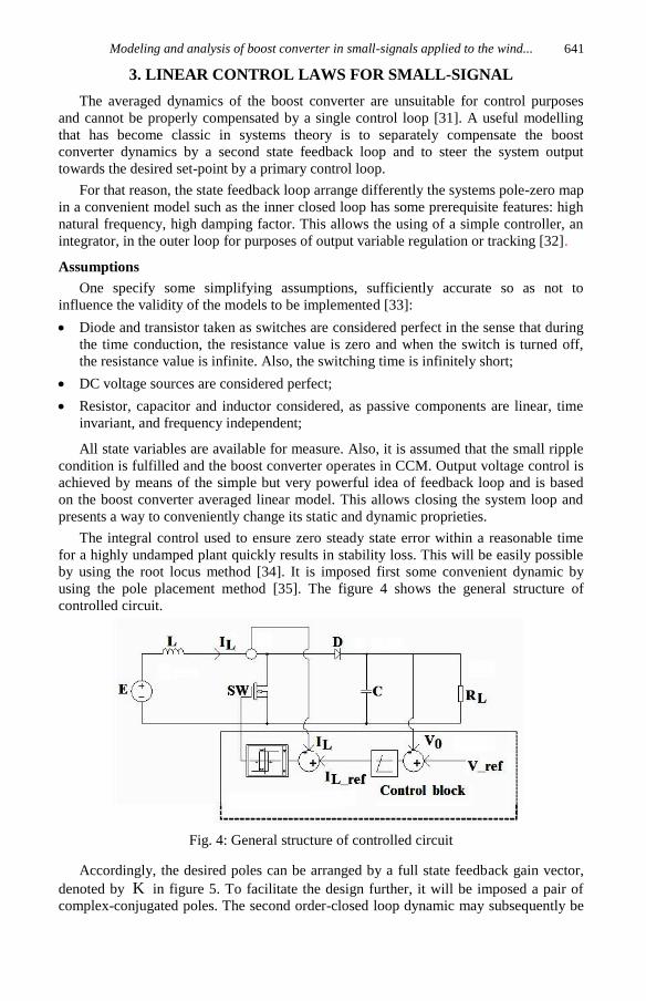
by using the root locus method [34]. It is imposed first some convenient dynamic by
using the pole placement method [35]. The figure 4 shows the general structure of
controlled circuit.
Fig. 4: General structure of controlled circuit
Accordingly, the desired poles can be arranged by a full state feedback gain vector,
denoted by K in figure 5. To facilitate the design further, it will be imposed a pair of
complex-conjugated poles. The second order-closed loop dynamic may subsequently be
N. Nisso et al.
642
adjusted via the root locus technique by choosing a convenient closed-loop pole
placement as the integral gain vector K varies.
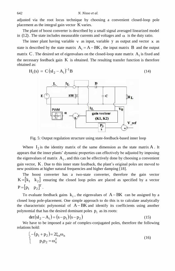
The plant of boost converter is described by a small signal averaged linearized model
in )12( . The state includes measurable currents and voltages and is the duty ratio.
The inner plant having variable v as input, variable y as output and vector x as
state is described by the state matrix BKAAi , the input matrix B and the output
matrix C . The desired set of eigenvalues on the closed-loop state matrix iA is fixed and
the necessary feedback gain K is obtained. The resulting transfer function is therefore
obtained as:
BAsIC)s(H1
i2i
(14)
Fig. 5: Output regulation structure using state-feedback-based inner loop
Where 2I is the identity matrix of the same dimension as the state matrix A . It
appears that the inner plants’ dynamic properties can effectively be adjusted by imposing
the eigenvalues of matrix iA , and this can be effectively done by choosing a convenient
gain vector, K . Due to this inner state feedback, the plant’s original poles are moved to
new positions at higher natural frequencies and higher damping [18].
The boost converter has a two-state converter, therefore the gain vector
21 kkK ensuring the closed loop poles are placed as specified by a vector
T21 ppP .
To evaluate feedback gains ik , the eigenvalues of BKA can be assigned by a
closed loop pole-placement. One simple approach to do this is to calculate analytically
the characteristic polynomial of BKA and identify its coefficients using another
polynomial that has the desired dominant poles ip as its roots:
21i2 pspsAsIdet (15)
We have to be imposed a pair of complex-conjugated poles, therefore the following
relations hold:
2n21
nn21
pp
2pp (16)

Modeling and analysis of boost converter in small-signals applied to the wind...
643
In )15( n being the desired closed-loop band width and n being the desired
closed-loop damping coefficient [36].
One can to use the Matlab command for finding the state feedback coefficients by
Ackerman formula as following:
P,B,AkeracK (17)
We find the closed-loop transfer function from the equation )14( and )17( .
221121211122121221122211221122112
12211111122i
kbakbakbakbaaaaas)aakbkb(s
)kba(b)akb(bsb)s(H
Where ija and ib are the elements of matrix A and B respectively. These
coefficients are defined by:
0a11 ; L
a e12
;
Ca e
21
;
CR
1a
e22 ;
L
vb Ce
1 ; C
ib Le
2 )19(
Now let us approach the outer loop, dedicated to outer voltage regulation. The
corresponding open loop transfer function is
)s(Hs
P)s(H i
iBO (20)
The aim is to choose a sufficiently high value for the integrator gain iP so as to
ensure the required closed-loop bandwidth with convenient damping. We use the root
locus method for this operation [37].
4. CONTROL IMPLEMENTATION FOR SMALL SIGNAL STABILITY
The Matlab simulation is carried out as shown in this section and the model circuit is
depicted in figure 6. The set of parameters chosen is shown in Table 1 and these
numerical values give good performance. The parameters of Table 2 were selected using
pole placement techniques after linearizing around a typical operating point.
Establishment time and robustness of the transient response are taken in account. In
order to choose the value of the gain vector described above by pole placement
technique, we analyze the root locus. Note that a linear analysis is performed once that
the small signal stability has been guaranteed. The linear analysis does not take into
account bilinear terms [38].
Table 1: Signal statistics of output voltage
Value (V) Time (s)
Max 27.06 1.85
Min 0.04886 //
Peak to peak 27.2 //
Mean 24.73 //
Median 25 //
RMS 24.79 //
The results are obtained using the previous equations. Figure 7 shows Matlab
simulations of the inductor voltage and current waveforms based on the steady state. The
Matlab simulation result of controlled voltage is shown in below figure 8.
It appears that our controller achieves better performance and the overshoot is 5.17
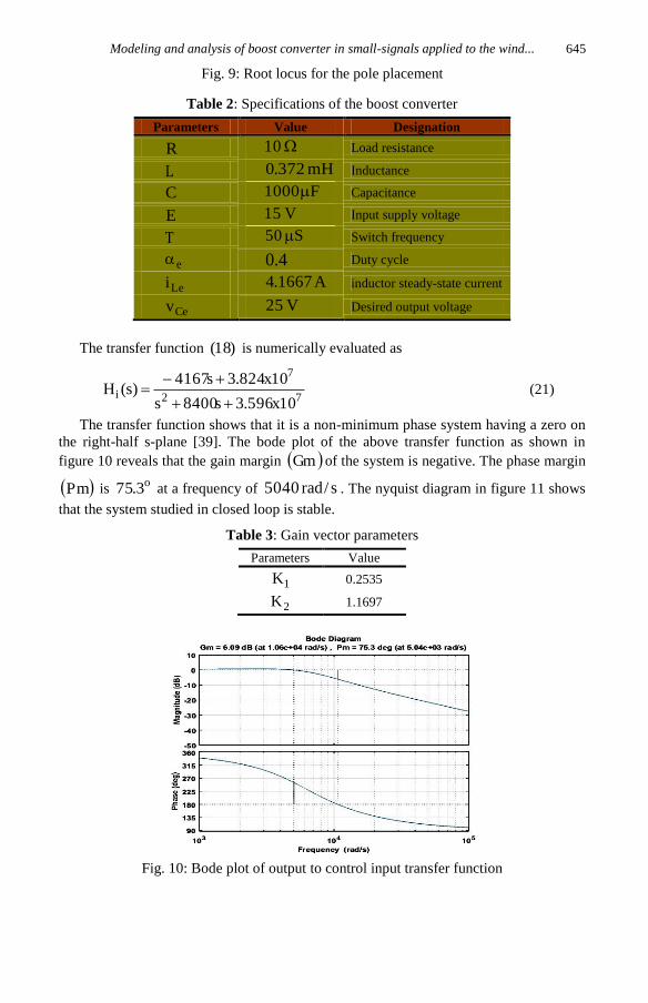
%. Figure 9 describes the root locus for system described by )20( and position of poles
for different values of controller gain )850,600,0(Pi .

N. Nisso et al.
644
Fig. 6: Boost converter Matlab/Simulink model
Fig. 7: The waveform of inductor voltage and
current of boost converter on the steady state
Fig. 8: Matlab simulation result of controlled voltage
Modeling and analysis of boost converter in small-signals applied to the wind...
645
Fig. 9: Root locus for the pole placement
Table 2: Specifications of the boost converter
Parameters Value Designation
R 10 Load resistance
L mH372.0 Inductance
C F1000 Capacitance
E V15 Input supply voltage
T S50 Switch frequency
e 4.0 Duty cycle
Lei A1667.4 inductor steady-state current
Cev V25 Desired output voltage
The transfer function )18( is numerically evaluated as
72
7
i10x596.3s8400s
10x824.3s4167)s(H
(21)
The transfer function shows that it is a non-minimum phase system having a zero on
the right-half s-plane [39]. The bode plot of the above transfer function as shown in
figure 10 reveals that the gain margin Gm of the system is negative. The phase margin
Pm is o3.75 at a frequency of 5040 s/rad . The nyquist diagram in figure 11 shows
that the system studied in closed loop is stable.
Table 3: Gain vector parameters
Parameters Value
1K 0.2535
2K 1.1697
Fig. 10: Bode plot of output to control input transfer function

N. Nisso et al.
646
Fig. 11: Nyquist diagram
5. CONCLUSIONS
In this paper, small-signal stability of linear control laws for boost converter have
been studied. The circuit model used in this study has been analyzed. This model
describesvariable relationships, where the energy in the storing passive elements
constitutes the perturbation energy with respect to the equilibrium point. The analysis
takes into account linear terms.
Once that small-signal stability for the linear control law has been demonstrated,
response frequency, root locus and pole placement techniques has been employed to
guarantee robustness and good transient response.
Contrary to classical control methods of boost converter, the technique here reported
guarantees small-signal stability of the boost converter. In our design, we have first
guaranteed small-signal stability of a linearly controlled boost converter by means of a
linear analysis. Thereafter, we have designed the feedback loop using pole placement
techniques. Observe that linearization constrains in the previous equations have been
used in the stability investigation.
Finally, as a possible direction for future research, this methodology can be applied
in the buck-boost converter. Also, it can be easily applied to a buckwhose dynamics
linked to bilinear terms are neglected. Another interesting future research topic is
associating pole placement to fuzzy control approach, for the trajectory tracking task in
boost converter.
NOMENCLATURE
Si , Load disturbance, A R , Load modeled as a linear resistor,
C , Capacitance of the capacitor, F L , Inductance of the inductor, H
D , Diode Cr , Lr , Equivalent series resistances,
LI , Li , Inductor current, A refLI , Reference Inductor current, A
CrefV , Cv , Cev , Cv~ , Cv~ , Capacitor
voltage, V
SW , Mosfet transistor considered as switch
OV , output voltage, V
refV , Reference voltage, V )t(u , eu , u~ , eu , Binary signal
, e ,~ , e , Duti ratio T , Considered as switching period, s
Lei , Li~
, i~
, Inductor steady-state current, A E , eE , E~
, Input supply voltage, V

Modeling and analysis of boost converter in small-signals applied to the wind...
647
x , x , State vector y , Output vector
t , time, s
K ,Gain vector iA , A , B , C , Matrices of the averaged
state space model
iH , Transfer function 2I , 2x2 identity matrix
ik , Feedback gains T21 ppP , Vector with elements
s , Laplace variable iP , Integrator gain
n , Desired closed-loop bandwidth, rad/s n , Desired closed-loop damping coef.
ija , ib , elements of matrix A an B respec. BOH , Open loop transfer function
Gm , Gain margin, dB Pm , Phase margin, °C
REFERENCES
[1] S. Nanda, M. Sengupta, and A. Sengupta, 'Modelling, Simulation, Fabrication,
Experiments and Real-Time Linear State Variable Feedback Control of Cuk
Converter using Pole Placement Technique', Journal of the Institution of Engineers,
Séries B, Vol. 95, N°1, pp. 55 - 62, 2014.
[2] C.-C. Hua, H.-C. Chiang, and C.-W. Chuang, 'Small signal analysis of a new boost
converter based on Sheppard–Taylor topology', Journal of the Chinese Institute of
Engineers, Vol. 37, N°3, pp. 346 - 357, 2014.
[3] M. Sai Krishna Reddy, C. Kalyani, M. Uthra, and D. Elangovan, 'A small signal
analysis of DC-DC boost converter', Indian Journal of Science and Technology, Vol.
8, S2, pp. 1 - 6, 2015.
[4] R. Kot, M. Rolak, and M. Malinowski, 'Comparison of maximum peak power
tracking algorithms for a small wind turbine', Mathematics and Computers in
Simulation, Vol. 91, C, pp. 29–40, 2013.
[5] M.H. Rashid, 'Power electronics handbook: devices, circuits and applications', Third
Edit. Elsevier Inc., 2011.
[6] M. Chadli, P. Borne, and B. Dubuisson,' Multiple Models Approach in Automation:
Takagi-Sugeno Fuzzy Systems', ISTE Ltd, 2013.
[7] S.R. Sanders, 'Nonlinear control of switching power converters', Massachusetts
Institute of Technology, 1989.
[8] J. Channegowda, B. Saritha, H.R. Chola, and G. Narayanan, 'Comparative evaluation
of switching and average models of a DC-DC boost converter for real-time
simulation', in IEEE Conecct, 2014, IEEE International Conference on Electronics,
Computing and Communication Technologies, pp. 1 - 6, 2014.
[9] J. Arau and Q. Jimenez, 'Improving large signal analysis in DC/DC converters with a
modified small signal model', PESC’92 Rec. 23rd Annual IEEE Power Electronics
Specialists Conference, 1992.
[10] F. Guinjoan, J. Calvente, A. Poveda, and L. Martínez, 'Large-signal modeling and
simulation of switching dc-dc converters', IEEE Transactions on Power
Electronics, Vol. 12, N°3, pp. 485 - 494, 1997.

N. Nisso et al.
648
[11] H. Chung, A. Ioinovici, and S. Member, 'Design of Feedback Gain Vector of Two-
State Basic PWM Multifeedback Regulators for Large-Signal Stability', Vol. 44,
N°8, pp. 676 - 683, 1997.
[12] I.M. Pop-Calimanu and F. Renken, 'New multiphase hybrid boost converter with
wide conversion ratio for PV system', International Journal of Photoenergy, Vol.
2014, 16 p., 2014.
[13] Y. Che, W. Zhang, L. Ge, and J. Zhang, 'A two-stage wind grid inverter with boost
converter', Journal of Applied Mathematics, Vol. 2014, Special N°2014, 5 p., 2014.
[14] B. Allaoua, B. Mebarki, and A. Laoufi, 'Applied on Boost DC-DC Converter Power
Supply for Electric Vehicle Propulsion System', International Journal of Vehicular
Technology, Vol. 2013, 9 p., 2013.
[15] J. Moreno-valenzuela and O. García-alarcón, 'On Control of a Boost DC-DC Power
Converter under Constrained Input', Complexity, Vol. 2017, N°3, pp. 1 - 11, 2017.
[16] K. Sundareswaran and V.T. Sreedevi, 'Design and development of feed-back
controller for a boost converter using a colony of foraging bees', Electric Power
Components and Systems, Vol. 37, N°5, pp. 465 - 477, 2009.
[17] T.T. Vu, 'Non-linear Dynamic Transformer Modelling and Optimum Control
Design of Switched-mode Power Supplies', National University of Ireland
Maynooth, 2014.
[18] B.-S. Lee, S.-K. Kim, J.-H. Park, and K.-B. Lee, 'Adaptive output voltage tracking
controller for uncertain DC/DC boost converter', International Journal Electronics,
Vol. 103, N°6, pp. 1002 - 1017, 2016.
[19] P.C. Sen Alexander, G. Perry, Guang Feng, Yan-Fei Liu, 'A Design Me1thod for PI-
like Fuzzy Logic Controllers for DC-DC Converter', IEEE Transactions on
Industrial Electronics, Vol. 54, N°5, pp. 2688 - 2696, 2007.
[20] F.D. Menga, N. Djongyang, D. Raïdandi, and R. Tchinda, 'A proportional integral
synthesis for a variable speed wind energy conversion system using permanent
magnet synchronous generator', African Journal of Science, Technology,
Innovation and Developpement, Vol. 8, N°2, pp. 166 -172, 2016.
[21] M.M. Shebani, T. Iqbal, and J.E. Quaicoe, 'Modified Droop Method Based on
Master Current Control for Parallel-Connected DC-DC Boost Converters', Journal
of Electrical and Computer Engineering, Vol. 2018, 14p., 2018.
[22] Branko L. Dokić and B. Blanuša, 'Power Electronics Converter and Regulator',
Switzerland: Springer International Publishing, 2015.
[23] R. Shenbagalakshmi and T. Sree Renga Raja, 'Observer based pole placement and
linear quadratic optimization for DC-DC converters', Journal of Electrical
Engineering, Vol. 12, N°4, pp. 1 - 8, 2012.
[24] A. Yazdani and R. Iravani, 'Voltage-Sourced Converters in Power Systems:
Modeling, Control, and Applications', John Wiley & Sons, Inc, 2010.
[25] S. Ang and A. Oliva, 'Power-Switching Converter', Second Edition, CRC Press,
2005.
[26] S.J. Ovaska and L.M. Sztandera, Eds., 'Soft Computing in Industrial Electronics',
Springer-Verlag, 2002.

Modeling and analysis of boost converter in small-signals applied to the wind...
649
[27] R. Shenbagalakshmi and T. Sree Renga Raja, 'Modelling and Simulation of Digital
Compensation Technique for dc–dc Converter by Pole Placement', Journal of the
Institution of Engineers, Series B, Vol. 96, N°3, pp. 265 - 271, 2015.
[28] I. Munteanu, A.I. Bratcu, N.-A. Cutululis, and E. Ceanga, 'Optimal control of wind
energy systems: towards a global approach', Springer-Verlag, 2008.
[29] M. Zhu and F.L. Luo, 'Graphical analytical method for power dc-dc converters:
Averaging binary tree structure representation', IEEE Transactions on Power
Electronics, Vol. 22, N°2, pp. 701 - 705, 2007.
[30] T. Ackermann, Ed., 'Wind Power in Power Systems', Vol. 8., John Wiley & Sons
Ltd, 2005.
[31] H. Sira-Ramírez and R. Silva-Ortigoza, 'Control Design Techniques in Power
Electronics Devices', Springer-Verlag London, 2006.
[32] C.H. Houpis and S.N. Sheldon, 'Linear Control System Analysis and Design with
Matlab', Sixth, CRC Press, 2013.
[33] A.M. Trzynadlowski, Ed., 'Power Electronic Converters and Systems: Frontiers
and Applications', The Institution of Engineering and Technology, 2015.
[34] A. Tewari, 'Modern Control Design With Matlab and Simulink', John Wiley &
Sons Ltd, 2002.
[35] D. Xue, Y. Chen, and D.P. Atherton, 'Linear Feedback Control Analysis and
Design with Matlab', SIAM, 2007.
[36] L.Y. Chang, K.H. Chao, and T.C. Chang, 'Application of high voltage ratio and low
ripple interleaved DC-DC converter for a fuel cell', Scientific World Journal, Vol.
2012, N°1, pp. 26 - 36, 2012.
[37] Mathworks, 'Control System ToolboxTM Getting Started Guide R2014b', Mathworks,
2014.
[38] H. Siraramirez, 'Design of P-I controllers for dc-to-dc power supplies via extended
linearization', International Journal of Control, Vol. 51, N°3, pp. 601 - 620, 1990.
[39] L. Qingfeng, L. Zhaoxia, S. Jinkun, and W. Huamin, 'A Composite PWM Control
Strategy for Boost Converter', Physics Procedia, Vol. 24, pp. 2053 - 2058, 2012.