model wcsp-jv system installation,...
TRANSCRIPT

SECTION 1: INTRODUCTIONSpacePak System Design.......................................Code Compliance....................................................Air Distribution Requirements..................................Air Distribution Components....................................Warranty Information...............................................Shipment of Unit......................................................
SECTION 2: SYSTEM INSTALLATIONStep 1: Locating The Unit........................................Step 2: Cutting Return Air Opening........................Step 3: Attaching Supply Air Plenum Adaptor.............Step 4: Setting The Unit.......................................... Step 5: Connecting Water Lines..............................Step 6: Installing The Condensate Trap & Line.......
2223
5
5899
1011
Step 7: Wiring The Unit.......................................Step 8: Installing Air Distribution Components....
SECTION 3: START UP & OPERATIONSequence Of Operation.......................................Prior To Start-Up..................................................System Start-Up & Adjustments..........................Operating Setpoints.............................................Factors Affecting the Balance of the System.......
SECTION 4: MAINTENANCEBiannual Maintenance Checklist..........................If System Fails To Operate..................................Service/Troubleshooting Form.............................Parts List..............................................................Warranty...............................................................
11, 1213
1818181922
232324
25, 2627
IN UNITED STATES: 260 NORTH ELM ST. WESTFIELD, MA 01085 800-465-8558 / FAX (413) 564-5815IN CANADA: 7555 TRANMERE DRIVE, MISSISSAUGA, ONTARIO, L5S 1L4 (905) 670-5888 / FAX (905) 670-5782
Central Hydronic Coil Series2 to 5 Tons
Fan Coil Unit/Air SupplyComponents
MODELWCSP-JV SYSTEM
INSTALLATION,OPERATION
& MAINTENANCEMANUAL
WCSPV2-011845W30-WG0706-01
Back Cover

2
SPACEPAK SYSTEM DESIGNThe SpacePak WCSP-J V unit is a hydronic fan coil unitwhich utilizes chilled or heated water from a chiller or boiler to provide the conditioned air through the speciallydesigned prefabricated preinsulated flexible duct system.The system and its basic components operate the sameas in any conventional air-to-air cooling system.
The SpacePak system is covered by the following U.S.Patents: 3,507,354; 3,575,234; 3,596,936; 3,605,797;3,685,329; 4,045,977; 4,698,982; 926,673 and CanadianPatents: 891,292; 923,935; 923,936.
CODE COMPLIANCEFan coil unit installation must conform to the require-ments of the local authority having jurisdiction or, in the absence of such requirements, to the National Boardof Fire Underwriters regulations. Fan coil unit meets ETL listing requirements.
All electrical wiring must be in accordance with the National Electrical Code ANSI/NFPA No. 70-latest edition and any additional state or local code require-ments. If an external electrical source is utilized, the fancoil unit, when installed, must be electrically grounded.
NOTICE: It is a requirement of the InternationalMechanical Code (307.2.3 ) to install a secondary drainor an auxiliary drain pan where damage to any buildingcomponents will occur as a result of overflow from theequipment drain pan or stoppage in the condensatedrain piping from a cooling or an evaporator coil.
AIR DISTRIBUTION SYSTEM COMPONENT REQUIREMENTSAir distribution components installation must conform to the requirements of local authority having jurisdictionor, in the absence of such requirements, to the NationalFire Protection Association 90A or 90B.
Do not begin the installation of the system without a system layout and material take-off. If a layout plan is not already available and room terminator requirementsdetermined, then refer to the SpacePak ApplicationManual, SP9, to complete this information. A descriptionof air distribution system components is shown in Figure1.1.
Section 1: INTRODUCTION The following terms are used throughout this manual to bring attention to the presence of potentialhazards or to important information concerning theproduct:
Indicates an imminently hazardoussituation which, if not avoided, will result in death,serious injury or substantial property damage.
Indicates an imminently hazardoussituation which, if not avoided, could result indeath, serious injury or substantial property damage.
Indicates an imminently hazardous situation which, if not avoided, may result in minor injury or property damage.
NOTICE: Used to notify of special instructions oninstallation, operation or maintenance which areimportant to equipment but not related to personal injury hazards.
3
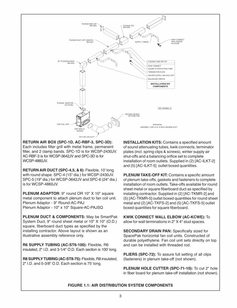
RETURN AIR BOx (SPC-1D, AC-RBF-3, SPC-3D):Each includes filter grill with metal frame, permanent filter, and 2 clamp bands. SPC-1D is for WCSP-2430JV.AC-RBF-3 is for WCSP-3642JV and SPC-3D is for WCSP-4860JV.
RETURN AIR DUCT (SPC-4,5, & 6): Flexible, 10' longwith round shape. SPC-4 (15" dia.) for WCSP-2430JV.SPC-5 (19" dia.) for WCSP-3642JV and SPC-6 (24" dia.)is for WCSP-4860JV .
PLENUM ADAPTOR: 9" round OR 10" X 10" squaremetal component to attach plenum duct to fan coil unit.Plenum Adaptor - 9" Round-AC-PAJPlenum Adaptor - 10" x 10" Square-AC-PAJSQ
PLENUM DUCT & COMPONENTS: May be SmartPakSystem Duct, 9" round sheet metal or 10" X 10" (O.D.)square, fiberboard duct types as specified by theinstalling contractor. Above layout is shown as an illustrative assembly reference only.
R6 SUPPLY TUBING (AC-ST6-100): Flexible, R6insulated, 2" I.D. and 3-1/4" O.D. Each section is 100' long.
R8 SUPPLY TUBING (AC-ST8-75): Flexible, R8 insulated,2" I.D. and 5-3/8" O.D. Each section is 75' long.
INSTALLATION KITS: Contains a specified amount of sound attenuating tubes, kwik-connects, terminatorplates (incl. spring clips & screws), winter supply airshut-offs and a balancing orifice set to complete installation of room outlets. Supplied in (2) [AC-ILKT-2]and (5) [AC-ILKT-5] outlet boxed quantities.
PLENUM TAKE-OFF KIT: Contains a specific amount of plenum take-offs, gaskets and fasteners to complete installation of room outlets. Take-offs available for roundsheet metal or square fiberboard duct as specified by installing contractor. Supplied in (2) [AC-TKMR-2] and(5) [AC-TKMR-5] outlet boxed quantities for round sheetmetal and (2) [AC-TKFS-2] and (5) [AC-TKFS-5] outletboxed quantities for square fiberboard.
KWIK CONNECT WALL ELBOW (AC-KCWE): Toallow for wall terminations in 2" X 4" stud spaces.
SECONDARY DRAIN PAN: Specifically sized forSpacePak horizontal fan coil units. Constructed ofdurable polyethylene. Fan coil unit sets directly on topand can be installed with threaded rod.
PLIERS (SPC-72): To assure full setting of all clips (fasteners) in plenum take-off (not shown).
PLENUM HOLE CUTTER (SPC-71-10): To cut 2" holein fiber board for plenum take-off installation (not shown).
FIGURE 1.1: AIR DISTRIBUTION SYSTEM COMPONENTS

4
Plenum DuctThe plenum duct can be run in practically any locationaccessible for the attachment of the supply tubing (seesuggested layouts in Figure 1.2). The plenum is normallylocated in the attic or basement, and it is usually moreeconomical to run the plenum where it will appreciablyshorten the lengths of two or more supply runs.
In some two-story split level homes, it may be advanta-geous to go from one level to another with the plenumduct. Whenever necessary, either between floors oralong the ceiling, the small size of the plenum makes iteasy to box in.
The fan coil unit is designed to operate with a totalexternal static pressure of 1.5" of water column (minimum1.2 - maximum 1.5). Excessive static pressure is anindication of too few outlets and may cause the coil tofreeze and some or all outlets to be noisy.
For systems with a bullhead tee installed as on Unit No.1 (Figure 1.3), the best results are obtained if not morethan 60% of the total number of system outlets areattached to any one branch of the tee. For systems witha branch tee installed as on Unit No. 2 (Figure1.3), notmore than 30% of the total number of system outletsshould be attached to the perpendicular branch of the tee.The larger system capacities (WCSP-3642/4860) are effected more by higher system static pressure than the smaller systems. Installation of the plenum tee clos-er than the minimum indicated in Fig. 1.3 will reduce per-formance of the system. No supply runs should beinstalled between unit outlet and this tee. Static readingson system should be taken before tee.
FIGURE 1.2: PLENUM/TUBING LAYOUT ExAMPLES (FOR GUIDANCE ONLY)
UNIT NO. 1
UNIT NO. 2
FAN COIL UNIT
FAN COIL UNIT
NO MORE THAN60% OF CAPACITY
ON ONE SIDE
30% MAX. OF CAPACITY
MINIMUM 18"
MINIMUM 18"
FIGURE 1.3: USE OF TEES

5
AAAAROOMTERMINATOR
FIGURE 1.4: TERMINATOR IN SOFFIT AREA
AAAAAAAAAAAAAAAAAAAAAAAAAAA
SUPPLYTUBING
ROOMTERMINATOR
FIGURE 1.5: TERMINATOR IN CLOSET TOP AREA
SECTION 2: SYSTEM INSTALLATION NOTICE: Before proceeding with the installation, werecommend reading through this section of the manual for an overall understanding of the air conditioning fan coil unit and air distribution systemcomponent installation procedures.
STEP 1: LOCATING THE UNITThe fan coil unit may be installed in an unconditionedspace (as long as it is protected from the weather) suchas an attic, garage or crawlspace, or a conditioned spacesuch as a basement, closet or utility room (see dimen-sions in Figures 2.2 and 2.3).
The fan coil unit is shipped set-up for horizontal supplyair discharge. This can be easily field converted to verti-cal discharge, as detailed on pg. 9 and Figures 2.9A and2.9B pg. 10.
When selecting a location, consider the locations (asshown in Figures 2.4, 2.5 and 2.6) of the return air box;routing of the plenum duct, supply tubing, refrigerantlines, condensate drain line; and all recommended clear-ances (see Figures 2.2).
Supply TubingIn the case of two-story or split-level applications, supplytubing may run from one story to another. It is smallenough to go in stud spaces, but this is often difficult in older homes because of hidden obstructions in studspaces. It is more common to run the supply tubing from the attic down through second story closets to the first story terminators.
Supply tubing runs in the corners of the second storyrooms can be boxed in and are hardly noticeable sinceoverall diameter is only 3-1/4" (Model Number AC-ST6-100).
Room TerminatorsTerminators should be located only in the ceiling or floorfor vertical discharge. Horizontal discharge is accept-able, but is sometimes more difficult to install. Twoexcellent spots for horizontal discharge are in the soffitarea above kitchen cabinets (see Figure 1.4) and in thetop portion of closets (see Figure 1.5).
Terminators should always be out of normal traffic patterns to prevent discharge air from blowing directly on occupants. And they should not be located directlyabove shelves or large pieces of furniture. Outside wall or corner locations are recommended if the room hasmore than one outside wall. Locating terminators awayfrom interior doors prevents short cycling of air to thereturn air box. SHIPMENT OF UNIT
Each fan coil unit is shipped in a single carton. Packed withthe unit, there are vibration isolation pads, a condensatetrap assembly and a factory installed primary float switch.
6
Model
Systemcapacity
(Nom. Tons)Water
InWaterOut
Cond.Drain(NPT)
ReturnInlet(Dia.)
Connections
C
WCSP-2430JVWCSP-3642JVWCSP-4860JV
2 - 2-1/23 - 3-1/2
4 - 5
ElectricalCharacteristics
230/1/60230/1/60230/1/60
7/8"7/8"7/8"
7/8"7/8"7/8"
115V/230V
3/4"3/4"3/4"
15"19"24"
Model
Systemcapacity
(Nom. Tons)
Std.CFM @
1.5" W.C.Motor
HPF.L.
Amps
No. ofRowsDeep
Blower
per Ton(GPM)
Ship.Flow RateWt.(lbs)
WCSP-2430JVWCSP-3642JVWCSP-4860JV
2 - 2-1/2 3 - 3-1/2
4 - 5
440, 550 3/43/43/4
5.6/2.87.6/4
10.6/5.4
666
2.4 120144171
660, 850880, 1150
2.42.4
CoilWheel Dia.
andWidth
10" x 6"
10" x 6"10" x 6"
Bottom Top
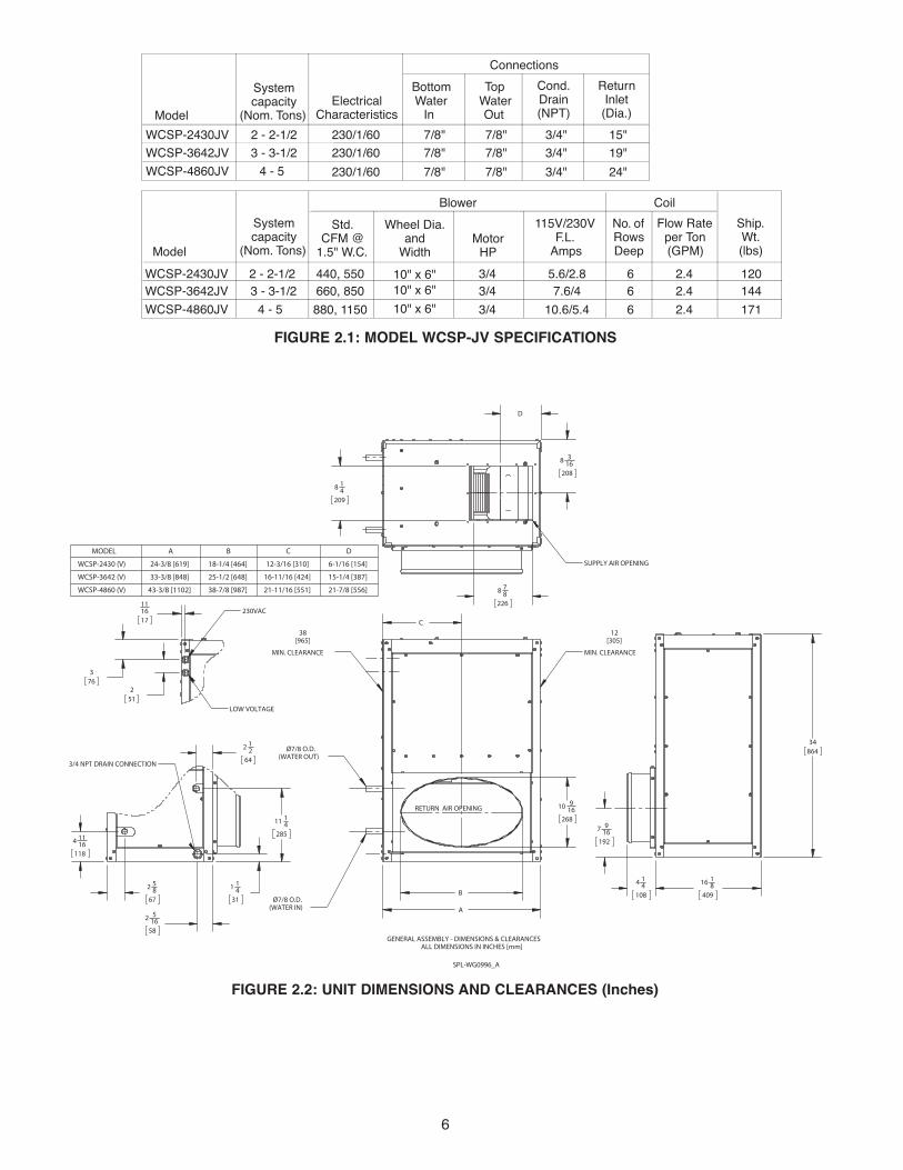
FIGURE 2.1: MODEL WCSP-JV SPECIFICATIONS
FIGURE 2.2: UNIT DIMENSIONS AND CLEARANCES (Inches)
A
10 916
268
B
C
Ø7/8 O.D.(WATER OUT)
Ø7/8 O.D.(WATER IN)
MIN. CLEARANCE MIN. CLEARANCE
16 18
409
7 916
192
4 14
108
34864
111617
376
251
LOW VOLTAGE
230VAC
4 1116
118
2 58
67
11 14
285
1 14
31
2 516
58
2 12
64
3/4 NPT DRAIN CONNECTION
8 14
209
8 78
226
D
8 316
208
SUPPLY AIR OPENING
RETURN AIR OPENING
SPL-WG0996_A
GENERAL ASSEMBLY - DIMENSIONS & CLEARANCESALL DIMENSIONS IN INCHES [mm]
12[305]
38[965]
MODEL A B C D
WCSP-2430 (V) 24-3/8 [619] 18-1/4 [464] 12-3/16 [310] 6-1/16 [154]
WCSP-3642 (V) 33-3/8 [848] 25-1/2 [648] 16-11/16 [424] 15-1/4 [387]
WCSP-4860 (V) 43-3/8 [1102] 38-7/8 [987] 21-11/16 [551] 21-7/8 [556]

7

8
STEP 2: CUTTING RETURN AIR OPENINGSelect exact location for return air box. Avoid installingbox in dining room, living room, kitchen, etc., unlessreturn air duct can be installed with at least two 90°bends (accomplished by splicing two return air ductstogether.)
For attic installations to raise fan coil unit up throughopening, cut return air opening 14-1/2" wide by the "A"dimension (Figure 2.7) of appropriate unit size. Theseopenings will accomodate the return air box with suffi-cient frame lip to cover the opening (see Figure 2.7).
Refer to the "Installation Tip" supplied with the returnair box.
If ceiling joists are on 16" centers, the 14-1/2" width of thereturn air box should fit between successive joists.Where joists run in the opposite direction, or to properlycenter the return, it may be necessary to cut joists andinstall headers.
For all wall return applications, cut the return air openingto accomodate the return air box (measure box itself).Remember, location of opening must allow for a 90° bendin the return air duct.
Check the opening for proper fit of the return air box. Donot install the return air box until the installation of theentire SpacePak system is completed, if you want to fitmaterials up through this hole.
FIGURE 2.3: TYPICAL CLOSET/UTILITY ROOM INSTALLATION
FIGURE 2.4: TYPICAL CLOSET INSTALLATION

9
STEP 3: ATTACHING SUPPLY AIR PLENUM ADAPTORRefer to Figure 2.6 and duct installation instructionssupplied with fan coil unit.
14-5/16"
FIGURE 2.7: RETURN AIR BOx FRAME DIMENSIONS
Measure return air box dimension"A" to determine length of opening. Height = 14-5/16"
DWG0045
#8 X 3/4MOUNTING SCREWS
(10 SUPPLIED)
10 INCH SQUARE SUPPLY AIRPLENUM ADAPTOR ASSEMBLY KIT
PART NO. AC-PAJSQ
SPL-WG0986_BESP-2436 (V) SHOWN
FIGURE 2.6: PLENUM ADAPTOR ASSEMBLY
STEP 4: SETTING THE UNITConstruct a platform for the fan coil unit, as shown inFigure 2.10. The platform can be constructed of 2 x 4 (minimum), 2 x 6, 2 x 8 and 2 x 10 lumber, as necessaryto achieve sufficient height so that proper condensatedrain line pitch of 1/4" per foot can be maintained. Figure2.11 shows the approximate normal allowable run of con-densate piping as a function of the framing lumber usedfor platform construction. The platform covering shouldbe 1/2" plywood minimum.
Attach vibration isolation pads (supplied inside fan coil unit) to platform covering as shown in Fig. 2.10.
Secure the platform to the joist or floor, depending onlocation selected for the fan coil unit. Make sure platformis level.
For locations where the fan coil unit will be suspended,suspend platform from overhead by 1/4" threaded rods.
NOTICE: Leave room on sides for servicing.
For installations with a return air box and return air duct, set fan coil unit on the platform with the ellipticalopening facing in the direction of the return air opening.The supply air plenum adaptor should overhang the platform. DO NOT let the adaptor support the weight ofthe unit.
Do not secure the unit to the platform, as the weight of theunit will hold it in position.

10
JVJVJV
FIGURE 2.7: MOUNTING PLATFORMS FOR VERTICAL INSTALLATIONS
FIGURE 2.11: CONDENSATE PIPING RUNS
LUMBER SIZE
MAXIMUM HORIZONTAL
2 x 4
8'
2 x 6
16'
2 x 8
24'
2 x 10
32'
STEP 5: CONNECTING WATERLINESConnect water lines from outdoor chiller unit to the fancoil unit in accordance with the chiller manufacturer’s recommendations.

11
ITEM123456
MALE ADAPTER, 3/4''DESCRIPTION
ELBOW 45 °, 3/4''
1/2'' PLUG3/4'' X 1/2'' BUSHINGTEE, 3/4''
P-TRAP, 3/4''
3/4'' P-TRAP ASS'Y KIT
WG0127B
NOTE: PIPE SECTIONS ARE FIELD SUPPLIED.
1
23
5
4
6
SEE NOTE
SECOND 3/4" MALE ADAPTER SUPPLIED FOR OVERFLOW CONNECTION
*
*
NOTICE: It is a requirement of the InternationalMechanical Code (307.2.3) to install a secondary drainor an auxiliary drain pan where damage to any buildingcomponents will occur as a result of overflow from theequipment drain pan or stoppage in the condensatedrain piping from a cooling or an evaporator coil.Follow local code requirements
Refer to Fig. 2.2 for primary and secondary condensatedrain locations. Components for the PVC condensatetrap are provided in a separate bag with fan coil unit (seeFig. 2.12) and should be cemented together with PVCpipe cement.
Do not use substitute trap. Do not cutoff or alter trap components.
Thread male adapter (see Fig. 2.12) into unit’s primarycondensate drain connection. Assemble and cementremaining components together. Then cement assemblyto male adapter. The 45° elbow provides an offset frombeneath unit suction line for access to clean-out plug.
Run a condensate line from the trap to a suitable drainthat’s in accordance with local codes. Make sure the lineis pitched 1/4" per foot.
STEP 6: INSTALLING THE CONDENSATE TRAP & LINE
STEP 7: WIRING THE UNITTurn off electrical power supply before
servicing. Contact with live electric components cancause shock or death.
All electrical and control wiring must be installed inaccordance with the codes listed in Section 1 of this manual. Wiring diagram is provided in Figure 2.13. Aseparate 208-230/60/1 power supply is recommendedfor the unit. Use standard 15-amp fuse and 16-gaugewire from power supply to unit.
Connect power supply to Terminals L1 and L2 on the highvoltage terminal block. Connect a ground wire to theequipment ground terminal located next to the high volt-age terminal block.
The low voltage transformer in the unit has a 208 volt tapin the primary winding (color coded RED). If unit is to beoperated with 208 volt electrical service, remove the 230volt ORANGE lead from the L2 terminal and connect the208 volt RED lead to the L2 terminal. Be sure to insulatethe end of the unused ORANGE lead.
Locate the room thermostat on a wall near the return airbox, between 40" to 48" from the floor. Connect the low-voltage thermostat wiring from the room thermostat tothe control board in the unit.
Connect low voltage from air handler to condensing unitas shown in figure 2.13.
Set DIP switches according to application. See page 13,SpacePak JV Series Control DIP switch settings.
NOTICE: The secondary drain connection requiresfield supplied components to complete installation.Follow local code requirements.
NOTICE: Never connect condensate line to a closeddrain system.
FIGURE 2.12: CONDENSATE TRAP ASSEMBLY

12
FIGURE 2.13: MODEL WCSP-JV WIRING SCHEMATIC
13
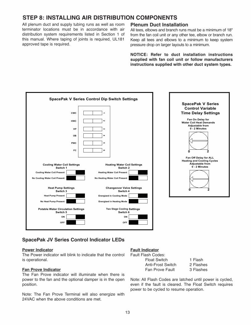
STEP 8: INSTALLING AIR DISTRIBUTION COMPONENTSAll plenum duct and supply tubing runs as well as roomterminator locations must be in accordance with airdistribution system requirements listed in Section 1 ofthis manual. Where taping of joints is required, UL181approved tape is required.
Plenum Duct InstallationAll tees, elbows and branch runs must be a minimum of 18"from the fan coil unit or any other tee, elbow or branch run.Keep all tees and elbows to a minimum to keep systempressure drop on larger layouts to a minimum.
NOTICE: Refer to duct installation instructions supplied with fan coil unit or follow manufacturersinstructions supplied with other duct system types.
CWC
HWC
HP
OB
PWC
FC
Cooling Water Coil Present
Cooling Water Coil SettingsSwitch 1
No Cooling Water Coil Present
Heat Pump Present
Heat Pump SettingsSwitch 3
No Heat Pump Present
ON
Potable Water Circulation SettingsSwitch 5
OFF
Heating Water Coil Present
Heating Water Coil SettingsSwitch 2
No Heating Water Coil Present
Energized in Cooling Mode
Changeover Valve SettingsSwitch 4
Energized in Heating Mode
ON
Fan Circulation SettingsSwitch 6
OFF
SpacePak V Series Control Dip Switch Settings
Fan On Delay forWater Coil Heat Demands
Adjustable from0 - 2 Minutes
SpacePak V SeriesControl Variable
Time Delay Settings
0 2
Fan Off Delay for ALLHeating and Cooling Cycles
Adjustable from0 - 2 Minutes
0 2
12
34
56
SpacePak JV Series Control Indicator LEDsPower IndicatorThe Power indicator will blink to indicate that the controlis operational.
Fan Prove IndicatorThe Fan Prove indicator will illuminate when there ispower to the fan and the optional damper is in the openposition.
Note: The Fan Prove Terminal will also energize with24VAC when the above conditions are met.
Fault IndicatorFault Flash Codes:
Float Switch 1 FlashAnti-Frost Switch 2 FlashesFan Prove Fault 3 Flashes
Note: All Flash Codes are latched until power is cycled,even if the fault is cleared. The Float Switch requirespower to be cycled to resume operation.
14
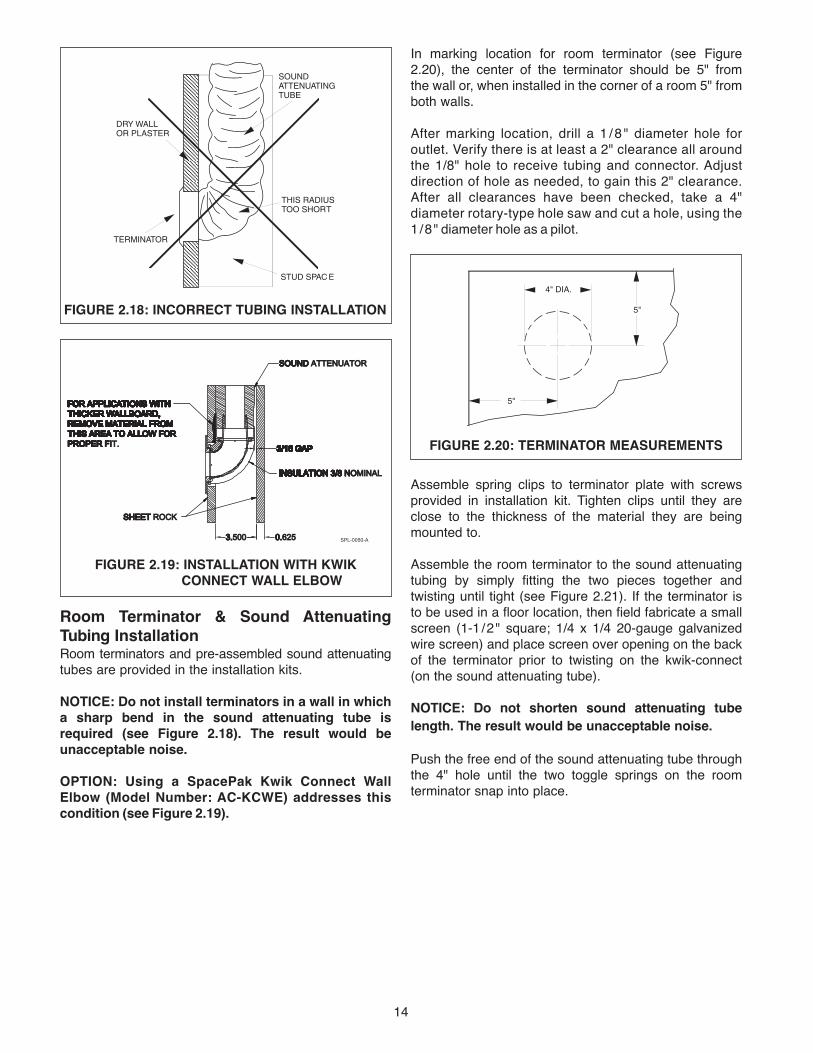
In marking location for room terminator (see Figure2.20), the center of the terminator should be 5" from the wall or, when installed in the corner of a room 5" fromboth walls.
After marking location, drill a 1 /8 " diameter hole foroutlet. Verify there is at least a 2" clearance all around the 1/8" hole to receive tubing and connector. Adjust direction of hole as needed, to gain this 2" clearance.After all clearances have been checked, take a 4" diameter rotary-type hole saw and cut a hole, using the1/8" diameter hole as a pilot.
Assemble spring clips to terminator plate with screwsprovided in installation kit. Tighten clips until they areclose to the thickness of the material they are beingmounted to.
Assemble the room terminator to the sound attenuatingtubing by simply fitting the two pieces together and twisting until tight (see Figure 2.21). If the terminator is to be used in a floor location, then field fabricate a smallscreen (1-1/2" square; 1/4 x 1/4 20-gauge galvanizedwire screen) and place screen over opening on the back of the terminator prior to twisting on the kwik-connect (on the sound attenuating tube).
NOTICE: Do not shorten sound attenuating tubelength. The result would be unacceptable noise.
Push the free end of the sound attenuating tube throughthe 4" hole until the two toggle springs on the roomterminator snap into place.
ININSINSULAINSULATINSULATIINSULATIOINSULATIONINSULATION INSULATION 3/8INSULATION 3/8 INSULATION 3/8 NINSULATION 3/8 NOINSULATION 3/8 NOMINALINSULATION 3/8 NOMINAL
SHEETSHEET SHEET ROCKSHEET ROCK
SOUNDSOUND SOUND ATTENUATORSOUND ATTENUATOR
33.3.5003.500 00.0.6250.625
3/163/16 3/16 GA3/16 GAP3/16 GAP
FOR
3/16 GAP
FOR
3/16 GAP
FOR APP
3/16 GAP
FOR APPL
3/16 GAP
FOR APPLICATIONS
3/16 GAP
FOR APPLICATIONS
3/16 GAP
FOR APPLICATIONS W
3/16 GAP
FOR APPLICATIONS WITH
3/16 GAP
FOR APPLICATIONS WITH
3/16 GAP
FOR APPLICATIONS WITH THICKER
3/16 GAP
FOR APPLICATIONS WITH THICKER
3/16 GAP
FOR APPLICATIONS WITH THICKER WAL
3/16 GAP
FOR APPLICATIONS WITH THICKER WALL
3/16 GAP
FOR APPLICATIONS WITH THICKER WALLBOARD
3/16 GAP
FOR APPLICATIONS WITH THICKER WALLBOARD,
3/16 GAP
FOR APPLICATIONS WITH THICKER WALLBOARD,
3/16 GAP
FOR APPLICATIONS WITH THICKER WALLBOARD, RE
3/16 GAP
FOR APPLICATIONS WITH THICKER WALLBOARD, REM
3/16 GAP
FOR APPLICATIONS WITH THICKER WALLBOARD, REMOVE MATERIAL FROM
3/16 GAP
FOR APPLICATIONS WITH THICKER WALLBOARD, REMOVE MATERIAL FROM
3/16 GAP
FOR APPLICATIONS WITH THICKER WALLBOARD, REMOVE MATERIAL FROM THIS A
3/16 GAP
FOR APPLICATIONS WITH THICKER WALLBOARD, REMOVE MATERIAL FROM THIS AR
3/16 GAP
FOR APPLICATIONS WITH THICKER WALLBOARD, REMOVE MATERIAL FROM THIS AREA TO ALL
3/16 GAP
FOR APPLICATIONS WITH THICKER WALLBOARD, REMOVE MATERIAL FROM THIS AREA TO ALLO
3/16 GAP
FOR APPLICATIONS WITH THICKER WALLBOARD, REMOVE MATERIAL FROM THIS AREA TO ALLOW FOR
3/16 GAP
FOR APPLICATIONS WITH THICKER WALLBOARD, REMOVE MATERIAL FROM THIS AREA TO ALLOW FOR PROPER
3/16 GAP
FOR APPLICATIONS WITH THICKER WALLBOARD, REMOVE MATERIAL FROM THIS AREA TO ALLOW FOR PROPER
3/16 GAP
FOR APPLICATIONS WITH THICKER WALLBOARD, REMOVE MATERIAL FROM THIS AREA TO ALLOW FOR PROPER F
3/16 GAP
FOR APPLICATIONS WITH THICKER WALLBOARD, REMOVE MATERIAL FROM THIS AREA TO ALLOW FOR PROPER FI
3/16 GAP
FOR APPLICATIONS WITH THICKER WALLBOARD, REMOVE MATERIAL FROM THIS AREA TO ALLOW FOR PROPER FIT.
3/16 GAP
FOR APPLICATIONS WITH THICKER WALLBOARD, REMOVE MATERIAL FROM THIS AREA TO ALLOW FOR PROPER FIT.
SPL-0050-A
FIGURE 2.19: INSTALLATION WITH KWIK CONNECT WALL ELBOW
SOUND ATTENUATING TUBE
THIS RADIUS TOO SHORT
STUD SPAC E
TERMINATOR
DRY WALL OR PLASTER
FIGURE 2.18: INCORRECT TUBING INSTALLATION
Room Terminator & Sound AttenuatingTubing InstallationRoom terminators and pre-assembled sound attenuatingtubes are provided in the installation kits.
NOTICE: Do not install terminators in a wall in whicha sharp bend in the sound attenuating tube isrequired (see Figure 2.18). The result would be unacceptable noise.
OPTION: Using a SpacePak Kwik Connect WallElbow (Model Number: AC-KCWE) addresses thiscondition (see Figure 2.19).
4" DIA.
5"
5"
FIGURE 2.20: TERMINATOR MEASUREMENTS

15
Supply Tubing InstallationKwik-connects and balancing orifices are provided in theInstallation Kits. Plenum take-offs, gaskets and fasten-ers are supplied in the separate plenum take-off kits.
Avoid sharp bends in the supply tubing (as well as thesound attenuating tube). The minimum radius bend is 4"(see Figure 2.22); however, wherever possible, hold to alarger radius.
At the plenum, all supply tubing connections must be a minimum of 18" from any plenum tee, plenum elbow or the fan coil unit.
Individual supply tubing runs must be a minimum of 6-feet, even if the distance between the sound attenuat-ing tubing and plenum is less than 6 feet.
Supply tubing comes in 100-foot sections (R8 tubing
comes in 50-foot sections and R6 tubing comes in 75-footsections) and may be cut to length with a knife or finetooth hacksaw.
For each supply tubing run, estimate and cut the lengthof tubing that will be needed between the plenum andsound attenuating tube. At the open end of the supplytubing a kwik-connect will be installed (see Figure 2.22).First, push back the cover and the insulation exposingapproximately 4" of the inner core. Fold in any tails orfrays that may be present after cutting the supply tubing.Second, hand compress the corrugations until they aredensely compacted 1-1/2" to 2" from the open end of thesupply tube. Third, thread kwik-connect into the innercore until snug. Fourth, pull the insulation and cover for-ward and tuck it into the deep groove on the back side ofthe kwik-connect. Fifth, wrap the connection securelywith UL181 approved tape..
When finished, simply twist together (see Figure 2.24)the kwik-connect on the sound attenuating tube, andwrap the connection securely with tape.
After attaching the supply tubing to the sound attenuatingtube, bring the open end of the tubing to the plenum.
To cut a hole in the plenum, refer to duct installationinstructions supplied with fan coil unit. Sheet metal ductrequires a 2-1/16" hole.
Remove the hole cut-out from the plenum. Make surethere is no “flap” left inside plenum that could block holeduring operation.
4" MINIMUM RADIUS
FIGURE 2.22: MINIMUM TUBING BEND
TUBING ROUTING
FIGURE 2.21: POSITIONING ROOM TERMINATOR
FIGURE 2.23: KWIK-CONNECT INSTALLATION
FIGURE 2.24: CONNECTING TUBING
Center the two spring clips on a line parallel to the direction of the tubing routing from the room terminator(see Figure 2.21). This is important since the weight of the tubing will have a tendency to cause a part of theterminator to pull away from the ceiling if the clips andtubing do not run parallel.
Then tighten the screws (attached to the terminator) untilthe terminator is snug against the ceiling or floor. Do not overtighten. For installations with floors or ceilingswhich are thicker than normal, longer toggle screws or special mounting plates may be required.

16
PLENUM
GASKET
Place the plenum take-off gasket on the back side of theplenum take-off and insert the assembly into the hole inthe plenum (see FIgure 2.25).
NOTICE: Gasket must be installed to seal plenumtake-off to prevent air leakage.
Orient the plenum take-off to match the curvature of theplenum duct. Hand insert the four plenum take offfasteners one at a time such that each clip reaches theinterior of the duct. Using the SpacePak pliers, snap thefasteners into place until they lock in place (see Figure2.26).
FIGURE 2.28: ORIFICE INSTALLATION
FIGURE 2.25: TAKE-OFF INSTALLATION
PLENUM
FASTENER
GASKET
PLENUM TAKE-OFF
GASKET
PLENUM TAKE-OFF
PLENUM
FASTENER
1. HAND INSERT FASTENER INTO PLENUM TAKE-OFF 2. WITH PLIERS, SNAP FASTENER INTO PLACE UNTIL IT LOCKS IN PLACE
FIGURE 2.26: PLENUM TAKE-OFF FASTENER INSTALLATION
NOTICE: All four fasteners must be installed to assure air tight fitting between plenum take-off andplenum.
In accordance with your calculations as to requirementsfor balancing orifices, mount the orifice in the outlet of the plenum take-off (see Figure 2.28), prior to attachingthe supply tubing.
Next, install a kwik-connect in the open end of the supplytubing, using the same procedures as before, and twisttogether kwik-connects on supply tubing and plenumtake-off. Wrap connection securely with tape.
17
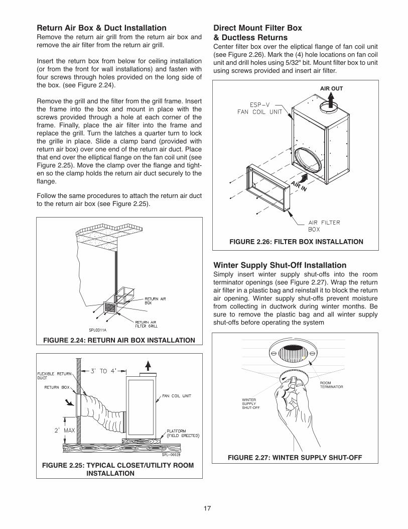
Return Air Box & Duct InstallationRemove the return air grill from the return air box andremove the air filter from the return air grill.
Insert the return box from below for ceiling installation(or from the front for wall installations) and fasten withfour screws through holes provided on the long side ofthe box. (see Figure 2.24).
Remove the grill and the filter from the grill frame. Insertthe frame into the box and mount in place with thescrews provided through a hole at each corner of theframe. Finally, place the air filter into the frame andreplace the grill. Turn the latches a quarter turn to lockthe grille in place. Slide a clamp band (provided withreturn air box) over one end of the return air duct. Placethat end over the elliptical flange on the fan coil unit (seeFigure 2.25). Move the clamp over the flange and tight-en so the clamp holds the return air duct securely to theflange.
Follow the same procedures to attach the return air ductto the return air box (see Figure 2.25).
FIGURE 2.25: TYPICAL CLOSET/UTILITY ROOMINSTALLATION
ROOM TERMINATOR
WINTERSUPPLYSHUT-OFF
FIGURE 2.27: WINTER SUPPLY SHUT-OFF
FIGURE 2.24: RETURN AIR BOx INSTALLATION
Direct Mount Filter Box & Ductless ReturnsCenter filter box over the eliptical flange of fan coil unit(see Figure 2.26). Mark the (4) hole locations on fan coilunit and drill holes using 5/32" bit. Mount filter box to unitusing screws provided and insert air filter.
Winter Supply Shut-Off InstallationSimply insert winter supply shut-offs into the roomterminator openings (see Figure 2.27). Wrap the returnair filter in a plastic bag and reinstall it to block the returnair opening. Winter supply shut-offs prevent moisturefrom collecting in ductwork during winter months. Besure to remove the plastic bag and all winter supplyshut-offs before operating the system
FIGURE 2.26: FILTER BOx INSTALLATION
AIR OUT
AIR IN

18
SECTION 3: START-UP & OPERATION SEQUENCE OF OPERATIONWhen power is turned on and thermostat fan switch is set to ON and the cooling indicator is set to OFF, the indoor fan motor is energized in approximately 2 min-utes. The outdoor unit is off.
When power is turned on and thermostat fan switch is set to ON or AUTO and the cooling indicator to COOL the indoor and outdoor units will start.
AUTO position on the thermostat will stop and start yoursystem when the temperature setting is satisfied. TheON position on the thermostat will stop the outdoor unitonly when the temperature setting is satisfied and theindoor unit will continue to run, recirculating indoor air.
The fan coil unit is equipped with a protective device called an anti-frost control which will automatically stopthe outdoor unit (while the indoor unit continues to run) ifice accumulates on the indoor unit evaporator coilcausing abnormal operating conditions. When theaccumulated ice has melted, the anti-frost control willrestart the outdoor unit.
The fan coil unit is equipped with primary float switch, and thesystem will automatically shut down if the drain pan is full of water(condensate) and not draining. The system requires service.
PRIOR TO START-UP 1. Check all electrical connections for tightness.
2. Check air filter has been installed in return air box or filter box.
3. Remove all winter supply shut-offs and store them in asafe place.
SYSTEM START-UP & ADJUSTMENTS1. Place thermostat fan switch in ON position and cooling
indicator in OFF position. In about 2 minutes, indoorunit blower will start.
2. Check blower operation for excess noise or vibration.
3. Check entire distribution system for leakage and applyadditional tape where necessary.
4. Measure/adjust blower voltage/speedsa. Remove the control box cover located on the side
of the unit.b. With the unit powered and operating from a
conventional thermostat, ensure there is no conditioningcall (Thermostat is satisfied) and switch the fan control to “Manual” or “On” to create a G call.
NOTE: IF NO AIRFLOW DURING W OR Y CALL,POTENTIOMETER MAY BE IN “OFF” POSITION.TURN CW TO ACHIEVE AIRFLOW
c. Place the ground/neutral probe in the lower right hole marked “COM” and the volt probe in the hole marked “Flo0” (for fan only, G call) and measure DC volts between0 and 5V. Adjust the potentiometer adjacent to the “Flo0” to achieve the desired volt reading. Repeat for remainingadjustments marked Flo1 through Flo4 as indicated on the label inside the cover. (Refer to Figure 3)
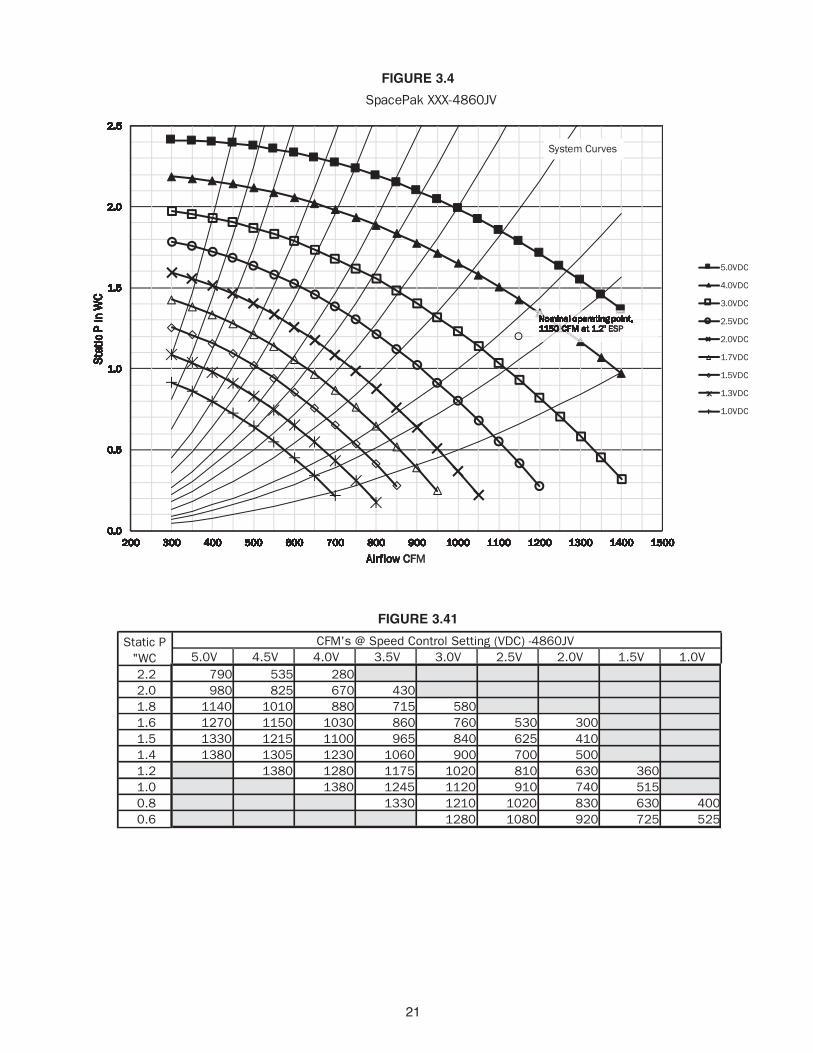
d. To determine unit airflow, in CFM, measure the voltage corresponding to the current conditioning call, and measure the external static pressure in the plenum, at least 18” from the unit or nearest transition point. Locate the static pressure on the left side of the charts (Figure 3.2/3.3/3.4) and read across until you reach the curve corresponding to the measured voltage. From the point where this crosses, drop a line straight down to read the airflow at the bottom of the chart. For system settings of 1.2" inch static pressure, refer to tables in Figures 3.21, 3.31 and 3.41.
e. To adjust airflow, locate the nearest system curve, and follow parallel to this curve while adjusting the signal voltage to achieve the desired airflow. If the static pressurefalls above or below the desired operating range for the given airflow, then the air delivery system must be adjusted. To lower static pressure, provide additional outlets to the system, to raise the static pressure, install restrictor orifices as described in the Installation and Operations Manual.
f. Replace the speed control cover.
Flo0Fan Only
Flo1Cooling
Flo2Heating
Flo3Stage 2Cooling
Flo4Stage 2Heating
FIGURE 3: SPEED CONTROL PANEL
4
3
2
1
0

19
FIGURE 3.2
FIGURE 3.21
OPERATING SETPOINTS
00.0.00.0
0
0.0
0.
0.0
0.5
0.0
0.5
1
0.0
0.5
1.
0.0
0.5
1.0
0.0
0.5
1.0
1
0.0
0.5
1.0
1.
0.0
0.5
1.0
1.5
0.0
0.5
1.0
1.5
2
0.0
0.5
1.0
1.5
2.
0.0
0.5
1.0
1.5
2.0
0.0
0.5
1.0
1.5
2.0
2
0.0
0.5
1.0
1.5
2.0
2.
0.0
0.5
1.0
1.5
2.0
2.5
0.0
0.5
1.0
1.5
2.0
2.5
20.0
0.5
1.0
1.5
2.0
2.5
200.0
0.5
1.0
1.5
2.0
2.5
2000.0
0.5
1.0
1.5
2.0
2.5
200 20.0
0.5
1.0
1.5
2.0
2.5
200 250.0
0.5
1.0
1.5
2.0
2.5
200 2500.0
0.5
1.0
1.5
2.0
2.5
200 250 30.0
0.5
1.0
1.5
2.0
2.5
200 250 300.0
0.5
1.0
1.5
2.0
2.5
200 250 3000.0
0.5
1.0
1.5
2.0
2.5
200 250 300 30.0
0.5
1.0
1.5
2.0
2.5
200 250 300 350.0
0.5
1.0
1.5
2.0
2.5
200 250 300 3500.0
0.5
1.0
1.5
2.0
2.5
200 250 300 350 40.0
0.5
1.0
1.5
2.0
2.5
200 250 300 350 400.0
0.5
1.0
1.5
2.0
2.5
200 250 300 350 4000.0
0.5
1.0
1.5
2.0
2.5
200 250 300 350 400 40.0
0.5
1.0
1.5
2.0
2.5
200 250 300 350 400 450.0
0.5
1.0
1.5
2.0
2.5
200 250 300 350 400 4500.0
0.5
1.0
1.5
2.0
2.5
200 250 300 350 400 450 50.0
0.5
1.0
1.5
2.0
2.5
200 250 300 350 400 450 500.0
0.5
1.0
1.5
2.0
2.5
200 250 300 350 400 450 5000.0
0.5
1.0
1.5
2.0
2.5
200 250 300 350 400 450 500 50.0
0.5
1.0
1.5
2.0
2.5
200 250 300 350 400 450 500 550.0
0.5
1.0
1.5
2.0
2.5
200 250 300 350 400 450 500 5500.0
0.5
1.0
1.5
2.0
2.5
200 250 300 350 400 450 500 550 60.0
0.5
1.0
1.5
2.0
2.5
200 250 300 350 400 450 500 550 600.0
0.5
1.0
1.5
2.0
2.5
200 250 300 350 400 450 500 550 6000.0
0.5
1.0
1.5
2.0
2.5
200 250 300 350 400 450 500 550 600 60.0
0.5
1.0
1.5
2.0
2.5
200 250 300 350 400 450 500 550 600 650.0
0.5
1.0
1.5
2.0
2.5
200 250 300 350 400 450 500 550 600 6500.0
0.5
1.0
1.5
2.0
2.5
200 250 300 350 400 450 500 550 600 650 70.0
0.5
1.0
1.5
2.0
2.5
200 250 300 350 400 450 500 550 600 650 700.0
0.5
1.0
1.5
2.0
2.5
200 250 300 350 400 450 500 550 600 650 7000.0
0.5
1.0
1.5
2.0
2.5
200 250 300 350 400 450 500 550 600 650 700 70.0
0.5
1.0
1.5
2.0
2.5
200 250 300 350 400 450 500 550 600 650 700 750.0
0.5
1.0
1.5
2.0
2.5
200 250 300 350 400 450 500 550 600 650 700 7500.0
0.5
1.0
1.5
2.0
2.5
200 250 300 350 400 450 500 550 600 650 700 750 80.0
0.5
1.0
1.5
2.0
2.5
200 250 300 350 400 450 500 550 600 650 700 750 800.0
0.5
1.0
1.5
2.0
2.5
200 250 300 350 400 450 500 550 600 650 700 750 8000.0
0.5
1.0
1.5
2.0
2.5
200 250 300 350 400 450 500 550 600 650 700 750 800 80.0
0.5
1.0
1.5
2.0
2.5
200 250 300 350 400 450 500 550 600 650 700 750 800 850.0
0.5
1.0
1.5
2.0
2.5
200 250 300 350 400 450 500 550 600 650 700 750 800 8500.0
0.5
1.0
1.5
2.0
2.5
200 250 300 350 400 450 500 550 600 650 700 750 800 850 90.0
0.5
1.0
1.5
2.0
2.5
200 250 300 350 400 450 500 550 600 650 700 750 800 850 900.0
0.5
1.0
1.5
2.0
2.5
200 250 300 350 400 450 500 550 600 650 700 750 800 850 9000.0
0.5
1.0
1.5
2.0
2.5
200 250 300 350 400 450 500 550 600 650 700 750 800 850 900
S
0.0
0.5
1.0
1.5
2.0
2.5
200 250 300 350 400 450 500 550 600 650 700 750 800 850 900
St
0.0
0.5
1.0
1.5
2.0
2.5
200 250 300 350 400 450 500 550 600 650 700 750 800 850 900
Sta
0.0
0.5
1.0
1.5
2.0
2.5
200 250 300 350 400 450 500 550 600 650 700 750 800 850 900
Stat
0.0
0.5
1.0
1.5
2.0
2.5
200 250 300 350 400 450 500 550 600 650 700 750 800 850 900
Stat
i
0.0
0.5
1.0
1.5
2.0
2.5
200 250 300 350 400 450 500 550 600 650 700 750 800 850 900
Stat
ic
0.0
0.5
1.0
1.5
2.0
2.5
200 250 300 350 400 450 500 550 600 650 700 750 800 850 900
Stat
ic
0.0
0.5
1.0
1.5
2.0
2.5
200 250 300 350 400 450 500 550 600 650 700 750 800 850 900
Stat
ic P
0.0
0.5
1.0
1.5
2.0
2.5
200 250 300 350 400 450 500 550 600 650 700 750 800 850 900
Stat
ic P
0.0
0.5
1.0
1.5
2.0
2.5
200 250 300 350 400 450 500 550 600 650 700 750 800 850 900
Stat
ic P
i
0.0
0.5
1.0
1.5
2.0
2.5
200 250 300 350 400 450 500 550 600 650 700 750 800 850 900
Stat
ic P
in
0.0
0.5
1.0
1.5
2.0
2.5
200 250 300 350 400 450 500 550 600 650 700 750 800 850 900
Stat
ic P
in
0.0
0.5
1.0
1.5
2.0
2.5
200 250 300 350 400 450 500 550 600 650 700 750 800 850 900
Stat
ic P
in W
0.0
0.5
1.0
1.5
2.0
2.5
200 250 300 350 400 450 500 550 600 650 700 750 800 850 900
Stat
ic P
in W
C
0.0
0.5
1.0
1.5
2.0
2.5
200 250 300 350 400 450 500 550 600 650 700 750 800 850 900
Stat
ic P
in W
C
A
0.0
0.5
1.0
1.5
2.0
2.5
200 250 300 350 400 450 500 550 600 650 700 750 800 850 900
Stat
ic P
in W
C
Ai
0.0
0.5
1.0
1.5
2.0
2.5
200 250 300 350 400 450 500 550 600 650 700 750 800 850 900
Stat
ic P
in W
C
Air
0.0
0.5
1.0
1.5
2.0
2.5
200 250 300 350 400 450 500 550 600 650 700 750 800 850 900
Stat
ic P
in W
C
Airf
0.0
0.5
1.0
1.5
2.0
2.5
200 250 300 350 400 450 500 550 600 650 700 750 800 850 900
Stat
ic P
in W
C
Airfl
0.0
0.5
1.0
1.5
2.0
2.5
200 250 300 350 400 450 500 550 600 650 700 750 800 850 900
Stat
ic P
in W
C
Airflo
0.0
0.5
1.0
1.5
2.0
2.5
200 250 300 350 400 450 500 550 600 650 700 750 800 850 900
Stat
ic P
in W
C
Airflow
0.0
0.5
1.0
1.5
2.0
2.5
200 250 300 350 400 450 500 550 600 650 700 750 800 850 900
Stat
ic P
in W
C
Airflow
0.0
0.5
1.0
1.5
2.0
2.5
200 250 300 350 400 450 500 550 600 650 700 750 800 850 900
Stat
ic P
in W
C
Airflow C
0.0
0.5
1.0
1.5
2.0
2.5
200 250 300 350 400 450 500 550 600 650 700 750 800 850 900
Stat
ic P
in W
C
Airflow CF
0.0
0.5
1.0
1.5
2.0
2.5
200 250 300 350 400 450 500 550 600 650 700 750 800 850 900
Stat
ic P
in W
C
Airflow CFM
0.0
0.5
1.0
1.5
2.0
2.5
200 250 300 350 400 450 500 550 600 650 700 750 800 850 900
Stat
ic P
in W
C
Airflow CFM
SpacePak XXX-2430JV
5.0VDC
4.0VDC
3.0VDC
2.5VDC
2.0VDC
1.7VDC
1.5VDC
1.3VDC
1.0VDC
System Curves
Nominal operating point, 550 CFM at 1.2"
5.0V 4.5V 4.0V 3.5V 3.0V 2.5V 2.0V 1.5V 1.0V2.2 530 390 2502.0 766 652 550 351 1.8 828 740 598 5301.6 870 717 690 500 2501.5 819 762 575 3851.4 825 680 4751.2 750 600 2601.0 845 700 475 0.8 780 540 2700.6 865 630 400
Static P "WC
CFM's @ Speed Control Setting (VDC) -2430JV

20
FIGURE 3.3
FIGURE 3.31
00.0.00.0
0
0.0
0.
0.0
0.5
0.0
0.5
1
0.0
0.5
1.
0.0
0.5
1.0
0.0
0.5
1.0
1
0.0
0.5
1.0
1.
0.0
0.5
1.0
1.5
0.0
0.5
1.0
1.5
2
0.0
0.5
1.0
1.5
2.
0.0
0.5
1.0
1.5
2.0
0.0
0.5
1.0
1.5
2.0
2
0.0
0.5
1.0
1.5
2.0
2.
0.0
0.5
1.0
1.5
2.0
2.5
0.0
0.5
1.0
1.5
2.0
2.5
20.0
0.5
1.0
1.5
2.0
2.5
200.0
0.5
1.0
1.5
2.0
2.5
2000.0
0.5
1.0
1.5
2.0
2.5
200 30.0
0.5
1.0
1.5
2.0
2.5
200 300.0
0.5
1.0
1.5
2.0
2.5
200 3000.0
0.5
1.0
1.5
2.0
2.5
200 300 40.0
0.5
1.0
1.5
2.0
2.5
200 300 400.0
0.5
1.0
1.5
2.0
2.5
200 300 4000.0
0.5
1.0
1.5
2.0
2.5
200 300 400 50.0
0.5
1.0
1.5
2.0
2.5
200 300 400 500.0
0.5
1.0
1.5
2.0
2.5
200 300 400 5000.0
0.5
1.0
1.5
2.0
2.5
200 300 400 500 60.0
0.5
1.0
1.5
2.0
2.5
200 300 400 500 600.0
0.5
1.0
1.5
2.0
2.5
200 300 400 500 6000.0
0.5
1.0
1.5
2.0
2.5
200 300 400 500 600 70.0
0.5
1.0
1.5
2.0
2.5
200 300 400 500 600 700.0
0.5
1.0
1.5
2.0
2.5
200 300 400 500 600 7000.0
0.5
1.0
1.5
2.0
2.5
200 300 400 500 600 700 80.0
0.5
1.0
1.5
2.0
2.5
200 300 400 500 600 700 800.0
0.5
1.0
1.5
2.0
2.5
200 300 400 500 600 700 8000.0
0.5
1.0
1.5
2.0
2.5
200 300 400 500 600 700 800 90.0
0.5
1.0
1.5
2.0
2.5
200 300 400 500 600 700 800 900.0
0.5
1.0
1.5
2.0
2.5
200 300 400 500 600 700 800 9000.0
0.5
1.0
1.5
2.0
2.5
200 300 400 500 600 700 800 900 10.0
0.5
1.0
1.5
2.0
2.5
200 300 400 500 600 700 800 900 100.0
0.5
1.0
1.5
2.0
2.5
200 300 400 500 600 700 800 900 1000.0
0.5
1.0
1.5
2.0
2.5
200 300 400 500 600 700 800 900 10000.0
0.5
1.0
1.5
2.0
2.5
200 300 400 500 600 700 800 900 1000 10.0
0.5
1.0
1.5
2.0
2.5
200 300 400 500 600 700 800 900 1000 110.0
0.5
1.0
1.5
2.0
2.5
200 300 400 500 600 700 800 900 1000 1100.0
0.5
1.0
1.5
2.0
2.5
200 300 400 500 600 700 800 900 1000 11000.0
0.5
1.0
1.5
2.0
2.5
200 300 400 500 600 700 800 900 1000 1100 10.0
0.5
1.0
1.5
2.0
2.5
200 300 400 500 600 700 800 900 1000 1100 120.0
0.5
1.0
1.5
2.0
2.5
200 300 400 500 600 700 800 900 1000 1100 1200.0
0.5
1.0
1.5
2.0
2.5
200 300 400 500 600 700 800 900 1000 1100 12000.0
0.5
1.0
1.5
2.0
2.5
200 300 400 500 600 700 800 900 1000 1100 1200 10.0
0.5
1.0
1.5
2.0
2.5
200 300 400 500 600 700 800 900 1000 1100 1200 130.0
0.5
1.0
1.5
2.0
2.5
200 300 400 500 600 700 800 900 1000 1100 1200 1300.0
0.5
1.0
1.5
2.0
2.5
200 300 400 500 600 700 800 900 1000 1100 1200 13000.0
0.5
1.0
1.5
2.0
2.5
200 300 400 500 600 700 800 900 1000 1100 1200 1300
S
0.0
0.5
1.0
1.5
2.0
2.5
200 300 400 500 600 700 800 900 1000 1100 1200 1300
St
0.0
0.5
1.0
1.5
2.0
2.5
200 300 400 500 600 700 800 900 1000 1100 1200 1300
Sta
0.0
0.5
1.0
1.5
2.0
2.5
200 300 400 500 600 700 800 900 1000 1100 1200 1300
Stat
0.0
0.5
1.0
1.5
2.0
2.5
200 300 400 500 600 700 800 900 1000 1100 1200 1300
Stat
i
0.0
0.5
1.0
1.5
2.0
2.5
200 300 400 500 600 700 800 900 1000 1100 1200 1300
Stat
ic
0.0
0.5
1.0
1.5
2.0
2.5
200 300 400 500 600 700 800 900 1000 1100 1200 1300
Stat
ic
0.0
0.5
1.0
1.5
2.0
2.5
200 300 400 500 600 700 800 900 1000 1100 1200 1300
Stat
ic P
0.0
0.5
1.0
1.5
2.0
2.5
200 300 400 500 600 700 800 900 1000 1100 1200 1300
Stat
ic P
0.0
0.5
1.0
1.5
2.0
2.5
200 300 400 500 600 700 800 900 1000 1100 1200 1300
Stat
ic P
i
0.0
0.5
1.0
1.5
2.0
2.5
200 300 400 500 600 700 800 900 1000 1100 1200 1300
Stat
ic P
in
0.0
0.5
1.0
1.5
2.0
2.5
200 300 400 500 600 700 800 900 1000 1100 1200 1300
Stat
ic P
in
0.0
0.5
1.0
1.5
2.0
2.5
200 300 400 500 600 700 800 900 1000 1100 1200 1300
Stat
ic P
in W
0.0
0.5
1.0
1.5
2.0
2.5
200 300 400 500 600 700 800 900 1000 1100 1200 1300
Stat
ic P
in W
C
0.0
0.5
1.0
1.5
2.0
2.5
200 300 400 500 600 700 800 900 1000 1100 1200 1300
Stat
ic P
in W
C
A
0.0
0.5
1.0
1.5
2.0
2.5
200 300 400 500 600 700 800 900 1000 1100 1200 1300
Stat
ic P
in W
C
Ai
0.0
0.5
1.0
1.5
2.0
2.5
200 300 400 500 600 700 800 900 1000 1100 1200 1300
Stat
ic P
in W
C
Air
0.0
0.5
1.0
1.5
2.0
2.5
200 300 400 500 600 700 800 900 1000 1100 1200 1300
Stat
ic P
in W
C
Airf
0.0
0.5
1.0
1.5
2.0
2.5
200 300 400 500 600 700 800 900 1000 1100 1200 1300
Stat
ic P
in W
C
Airfl
0.0
0.5
1.0
1.5
2.0
2.5
200 300 400 500 600 700 800 900 1000 1100 1200 1300
Stat
ic P
in W
C
Airflo
0.0
0.5
1.0
1.5
2.0
2.5
200 300 400 500 600 700 800 900 1000 1100 1200 1300
Stat
ic P
in W
C
Airflow
0.0
0.5
1.0
1.5
2.0
2.5
200 300 400 500 600 700 800 900 1000 1100 1200 1300
Stat
ic P
in W
C
Airflow
0.0
0.5
1.0
1.5
2.0
2.5
200 300 400 500 600 700 800 900 1000 1100 1200 1300
Stat
ic P
in W
C
Airflow C
0.0
0.5
1.0
1.5
2.0
2.5
200 300 400 500 600 700 800 900 1000 1100 1200 1300
Stat
ic P
in W
C
Airflow CF
0.0
0.5
1.0
1.5
2.0
2.5
200 300 400 500 600 700 800 900 1000 1100 1200 1300
Stat
ic P
in W
C
Airflow CFM
0.0
0.5
1.0
1.5
2.0
2.5
200 300 400 500 600 700 800 900 1000 1100 1200 1300
Stat
ic P
in W
C
Airflow CFM
SpacePak XXX-3642JV
5.0VDC
4.0VDC
3.0VDC
2.5VDC
2.0VDC
1.7VDC
1.5VDC
1.3VDC
1.0VDC
System Curves
NNoNomNomiNominNominaNominalNominal Nominal oNominal opNominal opeNominal operNominal operaNominal operatNominal operatiNominal operatinNominal operatingNominal operating Nominal operating pNominal operating poNominal operating poiNominal operating poinNominal operating pointNominal operating point,Nominal operating point, Nominal operating point, 8Nominal operating point, 85Nominal operating point, 850Nominal operating point, 850 Nominal operating point, 850 CNominal operating point, 850 CFNominal operating point, 850 CFMNominal operating point, 850 CFM Nominal operating point, 850 CFM aNominal operating point, 850 CFM atNominal operating point, 850 CFM at Nominal operating point, 850 CFM at 1Nominal operating point, 850 CFM at 1.Nominal operating point, 850 CFM at 1.2Nominal operating point, 850 CFM at 1.2"Nominal operating point, 850 CFM at 1.2" Nominal operating point, 850 CFM at 1.2" ENominal operating point, 850 CFM at 1.2" ESNominal operating point, 850 CFM at 1.2" ESPNominal operating point, 850 CFM at 1.2" ESP Nominal operating point, 850 CFM at 1.2" ESP 2Nominal operating point, 850 CFM at 1.2" ESP 2.Nominal operating point, 850 CFM at 1.2" ESP 2.7Nominal operating point, 850 CFM at 1.2" ESP 2.7VNominal operating point, 850 CFM at 1.2" ESP 2.7VDNominal operating point, 850 CFM at 1.2" ESP 2.7VDCNominal operating point, 850 CFM at 1.2" ESP 2.7VDC Nominal operating point, 850 CFM at 1.2" ESP 2.7VDC
5.0V 4.5V 4.0V 3.5V 3.0V 2.5V 2.0V 1.5V 1.0V2.2 650 460 2.0 860 735 610 1.8 1020 910 800 670 5501.6 1135 1045 955 800 730 505 1.5 1190 1115 1040 908 800 595 4001.4 1195 1075 1008 860 665 4801.2 1200 1073 975 780 625 3101.0 1180 1070 875 720 470 0.8 1160 960 810 580 3300.6 1035 875 675 460
CFM's @ Speed Control Setting (VDC) -3642JVStatic P "WC
21
FIGURE 3.4
FIGURE 3.41
00.0.00.0
0
0.0
0.
0.0
0.5
0.0
0.5
1
0.0
0.5
1.
0.0
0.5
1.0
0.0
0.5
1.0
1
0.0
0.5
1.0
1.
0.0
0.5
1.0
1.5
0.0
0.5
1.0
1.5
2
0.0
0.5
1.0
1.5
2.
0.0
0.5
1.0
1.5
2.0
0.0
0.5
1.0
1.5
2.0
2
0.0
0.5
1.0
1.5
2.0
2.
0.0
0.5
1.0
1.5
2.0
2.5
0.0
0.5
1.0
1.5
2.0
2.5
20.0
0.5
1.0
1.5
2.0
2.5
200.0
0.5
1.0
1.5
2.0
2.5
2000.0
0.5
1.0
1.5
2.0
2.5
200 30.0
0.5
1.0
1.5
2.0
2.5
200 300.0
0.5
1.0
1.5
2.0
2.5
200 3000.0
0.5
1.0
1.5
2.0
2.5
200 300 40.0
0.5
1.0
1.5
2.0
2.5
200 300 400.0
0.5
1.0
1.5
2.0
2.5
200 300 4000.0
0.5
1.0
1.5
2.0
2.5
200 300 400 50.0
0.5
1.0
1.5
2.0
2.5
200 300 400 500.0
0.5
1.0
1.5
2.0
2.5
200 300 400 5000.0
0.5
1.0
1.5
2.0
2.5
200 300 400 500 60.0
0.5
1.0
1.5
2.0
2.5
200 300 400 500 600.0
0.5
1.0
1.5
2.0
2.5
200 300 400 500 6000.0
0.5
1.0
1.5
2.0
2.5
200 300 400 500 600 70.0
0.5
1.0
1.5
2.0
2.5
200 300 400 500 600 700.0
0.5
1.0
1.5
2.0
2.5
200 300 400 500 600 7000.0
0.5
1.0
1.5
2.0
2.5
200 300 400 500 600 700 80.0
0.5
1.0
1.5
2.0
2.5
200 300 400 500 600 700 800.0
0.5
1.0
1.5
2.0
2.5
200 300 400 500 600 700 8000.0
0.5
1.0
1.5
2.0
2.5
200 300 400 500 600 700 800 90.0
0.5
1.0
1.5
2.0
2.5
200 300 400 500 600 700 800 900.0
0.5
1.0
1.5
2.0
2.5
200 300 400 500 600 700 800 9000.0
0.5
1.0
1.5
2.0
2.5
200 300 400 500 600 700 800 900 10.0
0.5
1.0
1.5
2.0
2.5
200 300 400 500 600 700 800 900 100.0
0.5
1.0
1.5
2.0
2.5
200 300 400 500 600 700 800 900 1000.0
0.5
1.0
1.5
2.0
2.5
200 300 400 500 600 700 800 900 10000.0
0.5
1.0
1.5
2.0
2.5
200 300 400 500 600 700 800 900 1000 10.0
0.5
1.0
1.5
2.0
2.5
200 300 400 500 600 700 800 900 1000 110.0
0.5
1.0
1.5
2.0
2.5
200 300 400 500 600 700 800 900 1000 1100.0
0.5
1.0
1.5
2.0
2.5
200 300 400 500 600 700 800 900 1000 11000.0
0.5
1.0
1.5
2.0
2.5
200 300 400 500 600 700 800 900 1000 1100 10.0
0.5
1.0
1.5
2.0
2.5
200 300 400 500 600 700 800 900 1000 1100 120.0
0.5
1.0
1.5
2.0
2.5
200 300 400 500 600 700 800 900 1000 1100 1200.0
0.5
1.0
1.5
2.0
2.5
200 300 400 500 600 700 800 900 1000 1100 12000.0
0.5
1.0
1.5
2.0
2.5
200 300 400 500 600 700 800 900 1000 1100 1200 10.0
0.5
1.0
1.5
2.0
2.5
200 300 400 500 600 700 800 900 1000 1100 1200 130.0
0.5
1.0
1.5
2.0
2.5
200 300 400 500 600 700 800 900 1000 1100 1200 1300.0
0.5
1.0
1.5
2.0
2.5
200 300 400 500 600 700 800 900 1000 1100 1200 13000.0
0.5
1.0
1.5
2.0
2.5
200 300 400 500 600 700 800 900 1000 1100 1200 1300 10.0
0.5
1.0
1.5
2.0
2.5
200 300 400 500 600 700 800 900 1000 1100 1200 1300 140.0
0.5
1.0
1.5
2.0
2.5
200 300 400 500 600 700 800 900 1000 1100 1200 1300 1400.0
0.5
1.0
1.5
2.0
2.5
200 300 400 500 600 700 800 900 1000 1100 1200 1300 14000.0
0.5
1.0
1.5
2.0
2.5
200 300 400 500 600 700 800 900 1000 1100 1200 1300 1400 10.0
0.5
1.0
1.5
2.0
2.5
200 300 400 500 600 700 800 900 1000 1100 1200 1300 1400 150.0
0.5
1.0
1.5
2.0
2.5
200 300 400 500 600 700 800 900 1000 1100 1200 1300 1400 1500.0
0.5
1.0
1.5
2.0
2.5
200 300 400 500 600 700 800 900 1000 1100 1200 1300 1400 15000.0
0.5
1.0
1.5
2.0
2.5
200 300 400 500 600 700 800 900 1000 1100 1200 1300 1400 1500
S
0.0
0.5
1.0
1.5
2.0
2.5
200 300 400 500 600 700 800 900 1000 1100 1200 1300 1400 1500
St
0.0
0.5
1.0
1.5
2.0
2.5
200 300 400 500 600 700 800 900 1000 1100 1200 1300 1400 1500
Sta
0.0
0.5
1.0
1.5
2.0
2.5
200 300 400 500 600 700 800 900 1000 1100 1200 1300 1400 1500
Stat
0.0
0.5
1.0
1.5
2.0
2.5
200 300 400 500 600 700 800 900 1000 1100 1200 1300 1400 1500
Stat
i
0.0
0.5
1.0
1.5
2.0
2.5
200 300 400 500 600 700 800 900 1000 1100 1200 1300 1400 1500
Stat
ic
0.0
0.5
1.0
1.5
2.0
2.5
200 300 400 500 600 700 800 900 1000 1100 1200 1300 1400 1500
Stat
ic
0.0
0.5
1.0
1.5
2.0
2.5
200 300 400 500 600 700 800 900 1000 1100 1200 1300 1400 1500
Stat
ic P
0.0
0.5
1.0
1.5
2.0
2.5
200 300 400 500 600 700 800 900 1000 1100 1200 1300 1400 1500
Stat
ic P
0.0
0.5
1.0
1.5
2.0
2.5
200 300 400 500 600 700 800 900 1000 1100 1200 1300 1400 1500
Stat
ic P
i
0.0
0.5
1.0
1.5
2.0
2.5
200 300 400 500 600 700 800 900 1000 1100 1200 1300 1400 1500
Stat
ic P
in
0.0
0.5
1.0
1.5
2.0
2.5
200 300 400 500 600 700 800 900 1000 1100 1200 1300 1400 1500
Stat
ic P
in
0.0
0.5
1.0
1.5
2.0
2.5
200 300 400 500 600 700 800 900 1000 1100 1200 1300 1400 1500
Stat
ic P
in W
0.0
0.5
1.0
1.5
2.0
2.5
200 300 400 500 600 700 800 900 1000 1100 1200 1300 1400 1500
Stat
ic P
in W
C
0.0
0.5
1.0
1.5
2.0
2.5
200 300 400 500 600 700 800 900 1000 1100 1200 1300 1400 1500
Stat
ic P
in W
C
A
0.0
0.5
1.0
1.5
2.0
2.5
200 300 400 500 600 700 800 900 1000 1100 1200 1300 1400 1500
Stat
ic P
in W
C
Ai
0.0
0.5
1.0
1.5
2.0
2.5
200 300 400 500 600 700 800 900 1000 1100 1200 1300 1400 1500
Stat
ic P
in W
C
Air
0.0
0.5
1.0
1.5
2.0
2.5
200 300 400 500 600 700 800 900 1000 1100 1200 1300 1400 1500
Stat
ic P
in W
C
Airf
0.0
0.5
1.0
1.5
2.0
2.5
200 300 400 500 600 700 800 900 1000 1100 1200 1300 1400 1500
Stat
ic P
in W
C
Airfl
0.0
0.5
1.0
1.5
2.0
2.5
200 300 400 500 600 700 800 900 1000 1100 1200 1300 1400 1500
Stat
ic P
in W
C
Airflo
0.0
0.5
1.0
1.5
2.0
2.5
200 300 400 500 600 700 800 900 1000 1100 1200 1300 1400 1500
Stat
ic P
in W
C
Airflow
0.0
0.5
1.0
1.5
2.0
2.5
200 300 400 500 600 700 800 900 1000 1100 1200 1300 1400 1500
Stat
ic P
in W
C
Airflow
0.0
0.5
1.0
1.5
2.0
2.5
200 300 400 500 600 700 800 900 1000 1100 1200 1300 1400 1500
Stat
ic P
in W
C
Airflow C
0.0
0.5
1.0
1.5
2.0
2.5
200 300 400 500 600 700 800 900 1000 1100 1200 1300 1400 1500
Stat
ic P
in W
C
Airflow CF
0.0
0.5
1.0
1.5
2.0
2.5
200 300 400 500 600 700 800 900 1000 1100 1200 1300 1400 1500
Stat
ic P
in W
C
Airflow CFM
0.0
0.5
1.0
1.5
2.0
2.5
200 300 400 500 600 700 800 900 1000 1100 1200 1300 1400 1500
Stat
ic P
in W
C
Airflow CFM
SpacePak XXX-4860JV
5.0VDC
4.0VDC
3.0VDC
2.5VDC
2.0VDC
1.7VDC
1.5VDC
1.3VDC
1.0VDC
System Curves
NNoNomNomiNominNominaNominalNominal Nominal oNominal opNominal opeNominal operNominal operaNominal operatNominal operatiNominal operatinNominal operatingNominal operating Nominal operating pNominal operating poNominal operating poiNominal operating poinNominal operating pointNominal operating point,Nominal operating point, Nominal operating point, 1Nominal operating point, 11Nominal operating point, 115Nominal operating point, 1150Nominal operating point, 1150 Nominal operating point, 1150 CNominal operating point, 1150 CFNominal operating point, 1150 CFMNominal operating point, 1150 CFM Nominal operating point, 1150 CFM aNominal operating point, 1150 CFM atNominal operating point, 1150 CFM at Nominal operating point, 1150 CFM at 1Nominal operating point, 1150 CFM at 1.Nominal operating point, 1150 CFM at 1.2Nominal operating point, 1150 CFM at 1.2"Nominal operating point, 1150 CFM at 1.2" Nominal operating point, 1150 CFM at 1.2" ENominal operating point, 1150 CFM at 1.2" ESNominal operating point, 1150 CFM at 1.2" ESPNominal operating point, 1150 CFM at 1.2" ESP Nominal operating point, 1150 CFM at 1.2" ESP
5.0V 4.5V 4.0V 3.5V 3.0V 2.5V 2.0V 1.5V 1.0V2.2 790 535 2802.0 980 825 670 430 1.8 1140 1010 880 715 5801.6 1270 1150 1030 860 760 530 3001.5 1330 1215 1100 965 840 625 4101.4 1380 1305 1230 1060 900 700 5001.2 1380 1280 1175 1020 810 630 3601.0 1380 1245 1120 910 740 515 0.8 1330 1210 1020 830 630 4000.6 1280 1080 920 725 525
CFM's @ Speed Control Setting (VDC) -4860JVStatic P "WC

22
5. Check that system static pressure is within acceptablelimits (minimum 1.2" WC - ,maximum 1.5" WC). Youcan use a U-tube manometer to check the external sta-tic pressure on the duct system.1. Puncture a ¼" diameter hole in the plenum duct at
least 18" from the fan coil unit. 2. Insert the high-side manometer tube into the hole so
that the end is approximately flush with the inside wallof the plenum, and perpendicular to the direction of airflow.
3. System static pressure should be between 1.2" and 1.5" WC.a. If the pressure is higher than 1.5" provide additional
supply runs to increase airflow or lower the fan speed by turning the fan speed adjustment for the current mode of operation counter-clockwise to reduce the static pressure.
b. If the pressure is lower than 1.2", look for leaks in the supply plenum, restrictions in the return system(including clogged filters) If more than the
recommended number of supply runs are installed,you may install flow restrictors (orifices) in these runs. If the number of runs is appropriate for the load, increase the static pressure by turning fan speed adjustment for the current mode of operationclockwise to increase the static pressure.
6. Check that blower motor amp draw compares with fan coil unit rating plate. Amp draw shown on plate is the FLA of motor (not the actual running amps) and willvary with the pressure and voltage.
7. Place the thermostat cooling indicator in COOL position,which will start the outdoor unit. Let the system run atleast 30 minutes to stabilize operating conditions.
8. For outdoor unit start-up, follow manufacturer’s instructions.
FACTORS AFFECTING THE BALANCE OF THE SYSTEMA. Room Terminators (Outlets): Based on the equip- ment selected, determine the recommended number of fully open outlets from Figure 3.1. FIGURE 3.1
1. The minimum or recommended number of outlets means fully open outlets. Any outlet having an orifice would be only a percentage of an outlet.
2. For systems with average supply tubing lengths of 15' or less, use column A. For systems with supply tubing lengths greater than 15', use column B.
NOTICE: The number of outlets and average length of thesupply tubing has a significant effect on the over-allsystem performance. It is highly recommended that theadjustment factors outlined in the SpacePak ApplicationManual are accounted for prior to any installation.
B. Orifice Combinations: Should orifices be required to balance the system (installed at plenum take-off), refer to the combinations listed in Figure 3.2.
FIGURE 3.2C. Supply Tubing Length: An outlet with a supply tubing length of 15' is considered one, fully opened outlet. For other lengths refer to Figure 3.3 for adjustment factors.
FIGURE 3.32" SUPPLY TUBING LENGTH ADJUSTMENT FACTOR CHART
FACTOR
RUN
1.18 1.14 1.11 1.06 1.0 .9 .8 .66
6' 8' 10' 12' 15' 20' 25' 30'
DESIRED NUMBEROF TERMINALS *
TERMINAL - ORIFICECOMBINATION
.5
.65
.85
1.00
1.15
1.30
1.50
1.65
1.70
1.80
1.85
1.95
(1) .5
(1) .35
(1) .15
(1)
(1) .5 + (1) .35
(2) .35
(1) .35 + (1) .15 or (1) + (1) .5 or (3) .5
(1) + (1) .35 or (2) .5 + (1) .35
(2) .15
(2) .35 + (1) .5
(1) + (1) .15
(3) .35
2.00 (2)
* For a room with more than two (2) terminals, combinations of the above may be used to achieve the desired fractional number.
NOMINALTONNAGE MODEL
WCSP-2430JV
WCSP-2430JV
WCSP-3642JV
WCSP-3642JV
WCSP-4860JV
WCSP-4860JV
2
2 1/2
3
3 1/2
4
5
A B
14
18
21
25
28
35
MINIMUM RECOMMENDEDNUMBER OF FULLY OPEN OUTLETS
12
15
18
21
26
30

23
SECTION 4: MAINTENANCE The SpacePak system has been designed to provideyears of trouble-free performance in normal installations.Examination by the homeowner at the beginning of eachcooling season, and in mid-season should assure continued, good performance. In addition, the systemshould be examined by a qualified service professional atleast once every year.
BEFORE EACH COOLING SEASON1. Check and clean air filter. The air filter is permanent
type. Remove and clean thoroughly with soap solutionand water.
Turn off electrical power supplybefore servicing. Contact with live electric compo-nents can cause shock or death.
2. Check fan coil unit. Turn off unit power disconnect switch and remove service access panels.
a. Inspect coil and blower wheel for build-up of dustand dirt. Clean with solvent and/ or water as necessary.
b. Replace service access panels and turn on unitpower disconnect switch.
3. Check that unit condensate drain is clear and freerunning, and plug is in cleanout.
4. For chiller or boiler unit, follow manufacturer’s mainte-nance instructions.
5. Follow “System Start-Up & Adjustments” procedures in Section 3 of this manual.
IF SYSTEM FAILS TO OPERATE1. Check that thermostat switch is set for proper mode
of operation and is set below room temperature.
2. Check that chiller or boiler unit is operating.
3. Check for tripped circuit breaker or blown fuse at the main fuse box. Reset breaker or replace blown- fuse with same size and type.

24
Customer / Dealer Data:
Name:
Address:
Tel (day) (eve)
Installing Dealer / Contractor:
Name:
Tel:
Equipment Data:
SPACEPAK Model # ESP / WCSP -
SPACEPAK Serial #
SPACEPAK Date of Installation:
Cond Unit Mfr:
Cond Unit Mod #:
Rated Capacity: BTUH; SEER:
Air-side Data:
Total # of outlets: ; Supply tube length: Ft
(avg)(Please sketch duct layout on reverse side of this sheet, noting all fit-tings and distances, including return duct size / length)
Air Filter: Size (LxHxD)
Type (pleated, etc):
Is the filter clean? (Y/N)
Static Pressure (Ps) in supply plenum: "WG(Measure at approximately 3 ft downstream of blower discharge)
Ps in return duct (downstream of filter, upstream of coil) "WG
SpacePak Motor: Amps (measured): Amps
Voltage (measured): Volts
Air Temperatures:
@ Return (indoor ambient): °FDB; °FWB
@ Condensing unit (outdoor ambient): °F
@ AHU (read 3 ft from fan discharge) °F
@ last supply outlet °F
Refrigeration-side Data:
Line sizes: Liquid Suction
Total equivalent length of lines: Ft; Vertical Rise: Ft.
@ Condensing Unit:
Liquid: psi; Temp: °F; Subcool: °F
Suction: psi; Temp: °F; Superheat: °F
@SpacePak:
Liquid: psi; Temp: °F; Subcool: °F
Suction: psi; Temp: °F; Superheat: °F
Approximate time running before taking readings: Hrs.
Did you adjust the TXV? (Y/N); (If yes, explain):
Refrigerant Charge (if weighed-in): lbs
R410a / R22 (circle one)
Installed options: (circle one)
sight glass filter/drier zone controls
Other:
Water Data: (where applicable)Line sizes: "; Length: FT
Water temperatures:
Suppy: °F; Return °F
Glycol?: (Y/N); % Solution:
NOTES:
Service / Troubleshooting FORM 1A

1
2
34
5
6
8 7 9 12 11
10
SPL-WG0997_A
2322
19 20* *
21*
13
15 16
17
18
14
19*
20
20 21
* NOT SHOWN
** APPLIES ONLY WHEN 115VAC CONVERSION KIT IS USED
*
**
**
25
FIGURE 4.1: MODEL WCSP-V GENERAL ASSEMBLY

26
SPACEPAK WCSP-V REPLACEMENT PARTS LIST
SPL-WG0997_A* ITEMS NOT SHOWN BUT CONNECTION POINTS ARE INDICATED ON EXPLODED VIEW.
***
ITEM PART DESCRIPTION UNIT SIZE PART NUMBER
1 BLOWER ACCESS PANEL ASSEMBLY
2430 462RWG0691-02
3642 462RWG0691-03
4860 462RWG0691-04
2 SIDE ACCESS PANEL ASSEMBLY ALL 462RWG1007-01
3 RETURN AIR PANEL ASSEMBLY
2430 463RWG0708-02
3642 463RWG0708-03
4860 463RWG0708-04
4 CONTROL BOX ACCESS PANEL ASSEMBLY ALL 458RWG0974-01
5 CENTER ACCESS PANEL ASSEMBLY ALL 458RWG0975-01
6 PLUMBING ACCESS PANEL ASSEMBLY ALL 458RWG0665-01
7 INSULATION, UPPER COIL TUBE ALL Y06RWG0663-01
8 INSULATION, LOWER COIL TUBE ALL Y06RWG0663-02
9 HYDRONIC COIL, VERTICAL
2430 W50RWG0660-02
3642 W50RWG0660-03
4860 W50RWG0660-04
10 BLOWER ASSEMBLY ALL W35RWG0802-10
11 PRIMARY DRAIN PAN ASSEMBLY
2430 455RWG1012-02
3642 455RWG1012-03
4860 455RWG1012-04
12 FLOAT SWITCH ASSEMBLY ALL 455RWG0543-01
13 TRANSFORMER ASSEMBLY ALL 460RWG1002-01
14 VOLTAGE SELECT TERMINAL STRIP ALL W09RWG0421-01
15 TERMINAL STRIP ALL W09RWG0422-01
16 GROUND LUG CONNECTOR ALL W09RWG0313-01
17 CONTROL BOARD ALL W11RWG0478-01
18 EVO-ECM SPEED CONTROL BOARD ALL W11RWG0806-01
19 EVO-ECM SPEED CONTROL CABLE ALL W11RWG0807-01
20 WIRE HARNESS, CONTROL BOARD TO EVO/ECM ALL 460RWG0944-01
21 WIRE HARNESS, CONTROL BOARD TO MOTOR ALL 460RWG0844-01
22 WIRING DIAGRAM LABEL, 230VAC ALL W49RWG0875-23
23 WIRING DIAGRAM LABEL, 115VAC ALL W49RWG0875-12

27
LIMITED WARRANTYCentral Air Conditioning Products
The “Manufacturer” warrants to the original owner at the original installation site that the Central AirConditioning Products (the “Product”) will be free from defects in material or workmanship for a period not toexceed one (1) year from the startup or eighteen (18) months from date of shipment from the factory, whicheveroccurs first. If upon examination by the Manufacturer the Product is shown to have a defect in material orworkmanship during the warranty period, the Manufacturer will repair or replace, at its option, that part of theProduct which is shown to be defective.
This limited warranty does not apply:a) if the Product has been subjected to misuse or neglect, has been accidentally or intentionally
damaged, has not been installed, maintained or operated in accordance with the furnished writteninstructions, or has been altered or modified in any way.
b) to any expenses, including labor or material, incurred during removal or reinstallation of the defectiveProduct or parts thereof.
c) to any workmanship of the installer of the Product.
This limited warranty is conditional upon:a) shipment, to the Manufacturer, of that part of the Product thought to be defective. Goods can only be
returned with prior written approval from the Manufacturer. All returns must be freight prepaid.b) determination, in the reasonable opinion of the Manufacturer, that there exists a defect in material or
workmanship.
Repair or replacement of any part under this Limited Warranty shall not extend the duration of the warrantywith respect to such repaired or replaced part beyond the stated warranty period.
THIS LIMITED WARRANTY IS IN LIEU OF ALL OTHER WARRANTIES, EITHER ExPRESS ORIMPLIED, AND ALL SUCH OTHER WARRANTIES, INCLUDING WITHOUT LIMITATION IMPLIEDWARRANTIES OF MERCHANTABILITY OR FITNESS FOR A PARTICULAR PURPOSE, ARE HEREBYDISCLAIMED AND ExCLUDED FROM THIS LIMITED WARRANTY. IN NO EVENT SHALL THEMANUFACTURER BE LIABLE IN ANY WAY FOR ANY CONSEQUENTIAL, SPECIAL, OR INCIDENTALDAMAGES OF ANY NATURE WHATSOEVER, OR FOR ANY AMOUNTS IN ExCESS OF THE SELLINGPRICE OF THE PRODUCT OR ANY PARTS THEREOF FOUND TO BE DEFECTIVE. THIS LIMITEDWARRANTY GIVES THE ORIGINAL OWNER OF THE PRODUCT SPECIFIC LEGAL RIGHTS. YOU MAYALSO HAVE OTHER RIGHTS WHICH MAY VARY BY EACH JURISDICTION.

IN UNITED STATES: 260 NORTH ELM ST. WESTFIELD, MA 01085 800-465-8558 / FAX (413) 564-5815IN CANADA: 7555 TRANMERE DRIVE, MISSISSAUGA, ONTARIO, L5S 1L4 (905) 670-5888 / FAX (905) 670-5782