model vc-22d
TRANSCRIPT

Model VC-22D Electronic Valve Controller
Installation / Operation / Maintenance Written for Engine Version 2.8.0

CLA-VAL VC-22D
Installation, Operation, and Maintenance Manual
N-VC-22D IOM V2.8.0-1.0.docx Page 2 of 209
Table of Contents 1 Introduction .......................................................................................................................................... 7
2 Installation ............................................................................................................................................ 8
2.1.1 IP65 or IP68 Backplate .......................................................................................................... 8
2.1.2 Panel Back Plate .................................................................................................................. 12
3 Electrical Wiring .................................................................................................................................. 17
3.1 Overview ..................................................................................................................................... 17
3.2 Power Supply .............................................................................................................................. 18
3.3 Inputs and Outputs ..................................................................................................................... 19
3.3.1 Analog Inputs ...................................................................................................................... 19
3.3.2 Digital Inputs ....................................................................................................................... 24
3.3.3 Analog Outputs ................................................................................................................... 25
3.3.4 Digital Outputs .................................................................................................................... 25
4 Screen Navigation ............................................................................................................................... 28
4.1 Home Screen ............................................................................................................................... 28
4.2 Navigation Buttons ..................................................................................................................... 30
4.3 Screen Map ................................................................................................................................. 31
4.3.1 Navigation Examples ........................................................................................................... 34
4.4 Basics ........................................................................................................................................... 36
4.4.1 Go Home ............................................................................................................................. 36
4.4.2 Numeric Entry ..................................................................................................................... 36
4.4.3 Alpha Numeric Entry ........................................................................................................... 37
4.4.4 Drop Down Selection .......................................................................................................... 39
4.4.5 Go Back ............................................................................................................................... 41
4.4.6 File Explorer ........................................................................................................................ 41
5 Initial Power Up ................................................................................................................................... 42
5.1 Select a ValvApp .......................................................................................................................... 42
5.2 Load a ValvApp ............................................................................................................................ 43
5.3 Configuration Wizard .................................................................................................................. 47
5.3.1 Introduction Screen ............................................................................................................ 48
5.3.2 Warning Screen ................................................................................................................... 49
5.3.3 Regional Settings ................................................................................................................. 50
5.3.4 Inputs .................................................................................................................................. 50

CLA-VAL VC-22D
Installation, Operation, and Maintenance Manual
N-VC-22D IOM V2.8.0-1.0.docx Page 3 of 209
5.3.5 Outputs ............................................................................................................................... 51
5.3.6 Solenoid Configuration ....................................................................................................... 52
5.3.7 DP Metering ........................................................................................................................ 53
5.3.8 Hostname ............................................................................................................................ 54
6 Setup ................................................................................................................................................... 55
6.1 System Settings ........................................................................................................................... 55
6.1.1 VC-22D Information ............................................................................................................ 55
6.1.2 ValvApp Backup .................................................................................................................. 58
6.1.3 Restore Application ............................................................................................................. 59
6.1.4 Export Application ............................................................................................................... 59
6.1.5 Import Application .............................................................................................................. 61
6.1.6 Time & Region ..................................................................................................................... 62
6.1.7 Unit Management ............................................................................................................... 65
6.1.8 Configure Logs ..................................................................................................................... 66
6.1.9 Export Logs .......................................................................................................................... 67
6.1.10 GSM/GPRS ........................................................................................................................... 68
6.1.11 LAN ...................................................................................................................................... 68
6.1.12 Remote Recopy ................................................................................................................... 69
6.1.13 Modbus ............................................................................................................................... 69
6.1.14 Remote Access .................................................................................................................... 74
6.1.15 Cloud Storage ...................................................................................................................... 76
6.1.16 Wireless ............................................................................................................................... 76
6.1.17 Web Interface ..................................................................................................................... 77
6.1.18 Security ............................................................................................................................... 78
6.1.19 Reboot ................................................................................................................................. 79
6.1.20 Engine Update ..................................................................................................................... 80
6.1.21 Diagnostics to USB .............................................................................................................. 81
6.1.22 Factory Reset....................................................................................................................... 82
6.1.23 Kernel Update ..................................................................................................................... 83
6.1.24 Configuration Wizard .......................................................................................................... 83
6.1.25 Display Brightness ............................................................................................................... 84
6.1.26 Shutoff Screen ..................................................................................................................... 84
6.2 Valve Control Settings ................................................................................................................. 85

CLA-VAL VC-22D
Installation, Operation, and Maintenance Manual
N-VC-22D IOM V2.8.0-1.0.docx Page 4 of 209
6.2.1 DP Metering ........................................................................................................................ 85
6.2.2 PID ....................................................................................................................................... 88
6.2.3 Control Curves ..................................................................................................................... 95
6.2.4 Averagers .......................................................................................................................... 100
6.2.5 Actions............................................................................................................................... 101
6.2.6 Signal Retransmission ....................................................................................................... 105
6.2.7 Totalizer ............................................................................................................................ 107
6.2.8 eDrive34 ............................................................................................................................ 107
6.2.9 Input Settings .................................................................................................................... 108
6.2.10 Output Settings ................................................................................................................. 113
7 Web Interface ................................................................................................................................... 117
7.1 Access the Web Interface ......................................................................................................... 117
7.2 Navigating the Web Interface ................................................................................................... 117
7.2.1 Information Page .............................................................................................................. 117
7.2.2 Logging Page ..................................................................................................................... 118
7.2.3 App Management Page ..................................................................................................... 118
7.2.4 Advanced Page .................................................................................................................. 119
8 Valve Operation ................................................................................................................................ 120
8.1 Setpoint Changes ...................................................................................................................... 120
8.1.1 Interactive Variable ........................................................................................................... 120
8.1.2 Remote/Local Setpoint ..................................................................................................... 121
8.2 Local Input Override .................................................................................................................. 123
8.3 Local Output Override ............................................................................................................... 126
9 Modbus Interface .............................................................................................................................. 126
9.1 Standard Mode ......................................................................................................................... 126
9.1.1 0x Registers (Coil Table) .................................................................................................... 127
9.1.2 1x Registers (Discrete Input Table) ................................................................................... 127
9.1.3 3x Registers (Analog Input Table) ..................................................................................... 127
9.1.4 4x Registers (Holding Table) .............................................................................................. 128
9.1.5 Data Types ......................................................................................................................... 147
9.2 Cla-Val Mode (Legacy) .............................................................................................................. 148
9.2.1 Modbus Base Registers ..................................................................................................... 148
9.2.2 Modbus Topkapi Registers ................................................................................................ 151

CLA-VAL VC-22D
Installation, Operation, and Maintenance Manual
N-VC-22D IOM V2.8.0-1.0.docx Page 5 of 209
9.2.3 Modbus Topkapi Integer Registers ................................................................................... 155
Appendix A: Standard ValvApp Library List ............................................................................................... 159
Appendix B: Standard ValvApp Worksheets ............................................................................................. 163
B.1 131-Flow-Mag-V2.0 or 131-Flow-X144D-V2.0 ................................................................................ 163
B.2 131-LvlAltitude-L-V2.0 .................................................................................................................... 165
B.3 131-LvlMod-L+Mag-V2.0 or 131-LvlMod-L+144D-V2.0 .................................................................. 167
B.4 131-LvlMod-L+X117D-V2.0 ............................................................................................................. 169
B.5 131-Position-X117D-V2.0 ................................................................................................................ 171
B.6 131-PressureReducing-P2-V2.0 ...................................................................................................... 173
B.7 131-PressureSustaining-P2-V2.0 ..................................................................................................... 175
B.8 133-Flow-DP+X117D-V2.0............................................................................................................... 177
B.9 133-Flow-P1+P2+X117D-V2.0 ......................................................................................................... 179
B.10 340-Flow-Mag-V1.0 ...................................................................................................................... 181
B.11 340-Flow-V1.0 ............................................................................................................................... 183
B.12 350-PressureSustaining-P1-V1.0 ................................................................................................... 185
B.13 350-PressureSustaining-V1.0 ........................................................................................................ 187
B.14 390-PressureReducing-P1-V1.0 .................................................................................................... 189
B.15 390-PressureReducing-V1.0 .......................................................................................................... 191
Appendix C: Standard ValvApp Wiring Diagrams ..................................................................................... 193
C.1 131-Flow-Mag-V2.0 ........................................................................................................................ 193
C.2 131-Flow-X144D-V2.0 ..................................................................................................................... 194
C.3 131-LvlAltitude-L-V2.0 .................................................................................................................... 195
C.4 131-LvlMod-L+Mag-V2.0................................................................................................................. 196
C.5 131-LvlMod-L+X117D-V2.0 ............................................................................................................. 197
C.6 131-LvlMod-L+X144D-V2.0 ............................................................................................................. 198
C.7 131-Position-X117D-V2.0 ................................................................................................................ 199
C.8 131-PressureReducing-P2-V2.0 ...................................................................................................... 200
C.9 131-PressureSustaining-P1-V2.0 ..................................................................................................... 201
C.10 133-Flow-DP+X117D-V2.0 ............................................................................................................. 202
C.11 133-Flow-P1+P2+X117D-V2.0 ....................................................................................................... 203
C.12 340-Flow-Mag-V1.0 ...................................................................................................................... 204
C.13 340-Flow-V1.0 ............................................................................................................................... 205
C.14 350-PressureSustaining-P1-V1.0 ................................................................................................... 206

CLA-VAL VC-22D
Installation, Operation, and Maintenance Manual
N-VC-22D IOM V2.8.0-1.0.docx Page 6 of 209
C.15 350-PressureSustaining-V1.0 ........................................................................................................ 207
C.16 390-PressureReducing-P2-V1.0 .................................................................................................... 208
C.17 390-PressureReducing-V1.0 .......................................................................................................... 209

CLA-VAL VC-22D
Installation, Operation, and Maintenance Manual
N-VC-22D IOM V2.8.0-1.0.docx Page 7 of 209
1 Introduction The VC-22D is a fully functional standalone controller for Cla-Val electronic valves. The unit contains
everything that is necessary to operate the valve with little or no configuration required by the end user.
The VC-22D also comes with several communication options to make integration with a SCADA or PLC
system seamless.
The controller has a display to show pertinent status information about the valve and 5 buttons for valve
operation. The VC-22D also has interchangeable back plates allowing it to be easily mounted in several
different scenarios. See FIGURE 1.1 below:
Figure 1.1
Navigation Buttons
Display Interchangeable Back Plate
(IP65 Shown Here)
Faceplate

CLA-VAL VC-22D
Installation, Operation, and Maintenance Manual
N-VC-22D IOM V2.8.0-1.0.docx Page 8 of 209
2 Installation The VC-22D can be mounted to walls, pipes, panel doors, din rails, and other miscellaneous objects
depending on the interchangeable backplate that’s purchased.
2.1.1 IP65 or IP68 Backplate The VC-22D can be purchased with an IP65 backplate or an IP68 backplate. The IP65 and IP68 backplates
have the same form factor, however the IP68 has cable glands that offer additional water proofing.
FIGURE 2.1 shows an exploded view of the VC-22D with an IP68 backplate and universal mounting
adapter (purchased separately).
Figure 2.1
The IP65 or IP68 backplate are used for mounting the VC-22D in a non-enclosed space. IP65 backplates
are good for indoor locations when heavy soaking with water is not expected. IP68 is best suited for
outdoor environments or in vaults where frequent contact with water is expected.

CLA-VAL VC-22D
Installation, Operation, and Maintenance Manual
N-VC-22D IOM V2.8.0-1.0.docx Page 9 of 209
FIGURE 2.2 shows common mounting scenarios using the IP65/68 backplate with the universal adapter
bracket.
Figure 2.2

CLA-VAL VC-22D
Installation, Operation, and Maintenance Manual
N-VC-22D IOM V2.8.0-1.0.docx Page 10 of 209
FIGURE 2.3 shows the overall dimensions for the unit.
Figure 2.3

CLA-VAL VC-22D
Installation, Operation, and Maintenance Manual
N-VC-22D IOM V2.8.0-1.0.docx Page 11 of 209
FIGURE 2.4 shows the dimensions for each mounting hole on the IP65/68 backplates, and the dimensions
for each mounting hole on the universal adapter plate.
Figure 2.4

CLA-VAL VC-22D
Installation, Operation, and Maintenance Manual
N-VC-22D IOM V2.8.0-1.0.docx Page 12 of 209
2.1.2 Panel Back Plate The VC-22D can be purchased with a panel backplate which allows for easy mounting to the door of an
electrical panel. FIGURE 2.5 shows an exploded view of the VC-22D with a panel backplate.
Figure 2.5

CLA-VAL VC-22D
Installation, Operation, and Maintenance Manual
N-VC-22D IOM V2.8.0-1.0.docx Page 13 of 209
FIGURE 2.6 below shows the dimensions of the VC-22D with a panel backplate.
Figure 2.6
Optional VC-1 conversion clips

CLA-VAL VC-22D
Installation, Operation, and Maintenance Manual
N-VC-22D IOM V2.8.0-1.0.docx Page 14 of 209
To mount the VC-22D on a control panel door, two screw holes must be drilled into the VC-22D’s back
panel. Two screw holes and a wireway hole must be drilled into the control panel door. See the drawing
in FIGURE 2.7 for dimensions.
Figure 2.7

CLA-VAL VC-22D
Installation, Operation, and Maintenance Manual
N-VC-22D IOM V2.8.0-1.0.docx Page 15 of 209
Sometimes, the VC-22D has been purchased to replace a previous generation VC-1 valve controller. In
these cases, it may be preferred to mount the VC-22D over the existing VC-1 panel hole. To do this,
remove the existing VC-1 and use the “optional VC-1 conversion clips” to mount the VC-22D in the
existing panel hole. The dimensions of the panel hole are shown in FIGURE 2.8. Before and after pictures
are shown in FIGURE 2.9 and FIGURE 2.10.
Figure 2.8
Figure 2.9

CLA-VAL VC-22D
Installation, Operation, and Maintenance Manual
N-VC-22D IOM V2.8.0-1.0.docx Page 16 of 209
Figure 2.10
If replacing a VC-1, it’s also likely the VC-22D must utilize the existing 120 VAC power supply and 120
VAC valve solenoids. If this is the case, an optional AC/DC panel mount power convertor may be
purchased from Cla-Val. The power convertor is mounted on the back of the VC-1 conversion clips using
the 4x 6-32 plastic screws as shown in FIGURE 2.11 below. See section 3.3.4 for wiring instructions on the
power convertor:
Figure 2.11

CLA-VAL VC-22D
Installation, Operation, and Maintenance Manual
N-VC-22D IOM V2.8.0-1.0.docx Page 17 of 209
3 Electrical Wiring
3.1 Overview The back plate of the VC-22D contains terminals for connecting a power supply, field IO, and serial
communication wires. See FIGURE 3.1 below to identify the terminals on the back plate:
Figure 3.1
A: RS232 and RS485 Modbus terminals
B: 4-20mA analog input terminals
C: Digital input terminals
D: 4-20mA analog output terminals
E: Digital output terminals (2 solid state 24 VDC sourcing outputs for solenoids, 2 dry contact relays)

CLA-VAL VC-22D
Installation, Operation, and Maintenance Manual
N-VC-22D IOM V2.8.0-1.0.docx Page 18 of 209
F: Power supply terminals
G: Ethernet cable port
H: Fuse block for solenoid digital outputs
3.2 Power Supply The VC-22D is designed to be a low power controller. It can be powered from a standard power supply,
solar panel, battery, or X143 generator. See TABLE 3.1 below for the VC-22D’s power supply
requirements.
Allowed Power Supply Voltage 12-24 VDC
Current Demand 300 mA at 24 VDC (steady state)
Power Demand 36 Watts (maximum) Table 3.1
The ratings provided in the TABLE 3.1 do not account for additional demand from analog inputs, digital
inputs, analog outputs, and digital outputs. To properly determine the amount of power and current
supplied to the VC-22D, the user must add in additional demands from field IO.
As shown in FIGURE 3.2, the VC-22D comes with two sets of V+ terminals, V- terminals, and GND
terminals. Either terminals may be used to power the unit, and the spare terminals have been included
to provide power to an external device if desired.

CLA-VAL VC-22D
Installation, Operation, and Maintenance Manual
N-VC-22D IOM V2.8.0-1.0.docx Page 19 of 209
Figure 3.2
3.3 Inputs and Outputs
3.3.1 Analog Inputs Each analog input can be configured in three different states as described below:
1. Isolated and current sinking
2. Non-isolated and current sinking
3. Non-isolated and current sourcing
Each analog input has a dip switch and three terminals. The dip switch controls whether the analog
input is isolated or non-isolated. The terminals used determine whether the input is current sinking or
current sourcing.
The VC-22D can work with the vast majority of 4-20mA sensors on the market because of the three
configuration options stated above. The VC-22D supports two wire loop powered, two wire field
powered, and four wire 4-20mA sensors.
The following sections assist with identifying the type of analog sensor being used and how to wire it
accordingly.

CLA-VAL VC-22D
Installation, Operation, and Maintenance Manual
N-VC-22D IOM V2.8.0-1.0.docx Page 20 of 209
3.3.1.1 2 Wire - Field Powered
If the analog sensor meets the requirements below, it is a grounded 2 wired field powered sensor:
1. Sensor has two wires
2. Power supply is in the field
3. 4-20mA loop is grounded in the field
The analog input should be configured as isolated and current sinking. FIGURE 3.3 shows the dip switch
position and a wiring diagram for this configuration.
Figure 3.3

CLA-VAL VC-22D
Installation, Operation, and Maintenance Manual
N-VC-22D IOM V2.8.0-1.0.docx Page 21 of 209
If the analog sensor meets the requirements below, it is an ungrounded 2 wired field powered sensor:
1. Sensor has two wires
2. Power supply is in the field
3. 4-20mA loop is not grounded in the field
The analog input should be configured as non-isolated and current sinking. FIGURE 3.4 shows the dip
switch position and a wiring diagram for this configuration.
Figure 3.4

CLA-VAL VC-22D
Installation, Operation, and Maintenance Manual
N-VC-22D IOM V2.8.0-1.0.docx Page 22 of 209
3.3.1.2 2 Wire - Loop Powered
If the analog sensor meets the requirements listed below, it is a 2 wired loop powered sensor:
1. Sensor has two wires
2. Power supply is not in the field
3. 4-20mA loop is not grounded in the field
The analog input should be configured as non-isolated and current sourcing. FIGURE 3.5 shows the dip
switch position and a wiring diagram for this configuration.
Figure 3.5

CLA-VAL VC-22D
Installation, Operation, and Maintenance Manual
N-VC-22D IOM V2.8.0-1.0.docx Page 23 of 209
3.3.1.3 4 wire
If the 4-20mA sensor has four wires, then the analog input should be configured as isolated and current
sinking. With four wire sensors, the power supply typically exists in the field and the wiring diagram
provided in FIGURE 3.6 can be used.
Figure 3.6

CLA-VAL VC-22D
Installation, Operation, and Maintenance Manual
N-VC-22D IOM V2.8.0-1.0.docx Page 24 of 209
Sometimes, the four wire sensor does not have a field power supply. In that case, the 24 VDC power can
be provided by the VC-22D as shown in FIGURE 3.7.
Figure 3.7
3.3.2 Digital Inputs The digital inputs are non-isolated and current sourcing. They must be connected to a relay (“dry
contact”) or NPN transistor. A wiring diagram for a digital input is shown in FIGURE 3.8.
Figure 3.8

CLA-VAL VC-22D
Installation, Operation, and Maintenance Manual
N-VC-22D IOM V2.8.0-1.0.docx Page 25 of 209
3.3.3 Analog Outputs The analog outputs are non-isolated and current sourcing. They must be connected to an isolated and
current sinking input on another device. A wiring diagram for an analog output is shown in FIGURE 3.9.
Figure 3.9
3.3.4 Digital Outputs The VC-22D has solid-state relay and mechanical relay digital outputs. The solid-state relays are non-
isolated and 24VDC current sourcing. They have a maximum current output of 1 amp. The mechanical
relays are isolated and current sinking. They are rated for 24 VDC or 250 VAC at 6 amps maximum.
The solid-state relays are typically used for 24 VDC solenoids, and the mechanical relays are used for
sending discrete output signals to other controllers. See FIGURE 3.10 wiring diagrams below digital
outputs.
Figure 3.10

CLA-VAL VC-22D
Installation, Operation, and Maintenance Manual
N-VC-22D IOM V2.8.0-1.0.docx Page 26 of 209
If AC solenoids are used, then an AC/DC converter must be used and the fuse block should be removed.
Cla-Val recommends our EPC module (sold separately) for AC/DC conversion. The EPC module does not
utilize mechanical relays which extends its service life much longer than “ice cube” relays which are
commonly used for AC/DC conversion. Cla-Val offers two EPC modules, our standard module and a
panel mount module. The standard EPC module is wired as shown in FIGURE 3.11.
Figure 3.11

CLA-VAL VC-22D
Installation, Operation, and Maintenance Manual
N-VC-22D IOM V2.8.0-1.0.docx Page 27 of 209
The panel mount EPC module is wired as shown in FIGURE 3.12.
Figure 3.12

CLA-VAL VC-22D
Installation, Operation, and Maintenance Manual
N-VC-22D IOM V2.8.0-1.0.docx Page 28 of 209
4 Screen Navigation
4.1 Home Screen The home screen includes a combination of graphics, text, and numeric displays providing pertinent
process information for monitoring/operating a Cla-Val electronic valve. The home screen is customized
for each ValvApp, but in general will include a Cla-Val valve graphic, simplified pilot system graphic, and
numeric display for each input/output. An example home screen from the 131-Flow-Mag-V2.0 ValvApp
is shown in FIGURE 4.1:
Figure 4.1
When the VC-22D unit is powered on and the boot sequence is completed, the home screen is
displayed. The home screen is the starting point to navigate to all other screens.
Various color standards are used and the home screen, and those color standards are described below:
1. Black text is used to display inputs, outputs, and variable values that are within normal limits
and have no overrides applied.
Figure 4.2
2. Green text is used to represent a value that has been assigned as a local set point (LSP) per
section 8.1.2.
Figure 4.3

CLA-VAL VC-22D
Installation, Operation, and Maintenance Manual
N-VC-22D IOM V2.8.0-1.0.docx Page 29 of 209
3. Blue text is used to represent a value that has been manually overridden per section 8.2 and 8.3.
Figure 4.4
4. Red text shows an analog input that is outside of the allowed range (below minimum or above
maximum). See section 6.2.9.4 for more information.
Figure 4.5
5. Orange text shows a value that is being overridden by an action per section 6.2.5.
Figure 4.6
6. Grey text shows a value that is being overridden via Modbus per section 9.
Figure 4.7
Various icons are used on the home screen and title bar. Their meaning is defined below:
1. - Indicates that the user is logged in and screen protection is disabled
2. - Indicates that an LSP is applied to a setpoint per section 8.1.2
3. - Indicates that all inputs are in RSP mode per section 8.1.2
4. - Indicates action 1 is enabled but not triggered
5. - Indicates action 1 is enabled and triggered
6. - Indicates voltage is currently being output to a solenoid

CLA-VAL VC-22D
Installation, Operation, and Maintenance Manual
N-VC-22D IOM V2.8.0-1.0.docx Page 30 of 209
4.2 Navigation Buttons The VC-22D has five buttons on the faceplate which are used to perform all navigation functions. Their
names are shown in FIGURE 4.8 below:
Figure 4.8
There are two types of button clicks, a short click and a long click. To issue a short click, press the button
momentarily for less than 1 second. To issue a long click, press and hold the button for more than 1
second. Throughout the remainder of this manual, assume all button presses are short clicks unless
otherwise stated. The graphics shown in FIGURE 4.9 will be used to indicate short and long clicks in
images:
Figure 4.9
Right/Outputs
OK/Home
Down/Settings
Left/Inputs
Up/Valve Configuration
Short Click Long Click

CLA-VAL VC-22D
Installation, Operation, and Maintenance Manual
N-VC-22D IOM V2.8.0-1.0.docx Page 31 of 209
4.3 Screen Map This section provides a map depicting how each screen in the VC-22D is accessed. The details of each
screen’s function are defined in subsequent sections. The map is split into multiple segments to reduce
complexity (see FIGURE 4.10 and FIGURE 4.11). The following paragraph describes how the map should
be interpreted, and additional examples for clarity are provided at the end of the section.
The map uses dark blue rectangles to represent screens. Each screen’s navigation icons are listed
underneath the screen and are drawn as white or light blue rectangles. A line connecting two screens
indicates that users can navigate from one screen to the other. The button in the middle of the line
indicates what must be pressed to navigate to the connected screen.

CLA-VAL VC-22D
Installation, Operation, and Maintenance Manual
N-VC-22D IOM V2.8.0-1.0.docx Page 32 of 209
Figure 4.10

CLA-VAL VC-22D
Installation, Operation, and Maintenance Manual
N-VC-22D IOM V2.8.0-1.0.docx Page 33 of 209
Figure 4.11

CLA-VAL VC-22D
Installation, Operation, and Maintenance Manual
N-VC-22D IOM V2.8.0-1.0.docx Page 34 of 209
4.3.1 Navigation Examples Below are some quick examples showing how to navigate to different screens using the screen maps from FIGURE 4.10 and FIGURE 4.11.
Compare the examples to the screen maps to understand FIGURE 4.10 and FIGURE 4.11 better.
4.3.1.1 Override AI2
Figure 4.12
Step 1: Start at home screen
Step 2: Long Left
Step 3: Highlight AI2
Step 4: Press OK

CLA-VAL VC-22D
Installation, Operation, and Maintenance Manual
N-VC-22D IOM V2.8.0-1.0.docx Page 35 of 209
4.3.1.2 Import Application
Figure 4.13
Step 1: Start at home screen
Step 2: Long Down
Step 4: Press OK
Step 3: Highlight Application Management
Step 5: Highlight Import Application
Step 6: Press OK

CLA-VAL VC-22D
Installation, Operation, and Maintenance Manual
N-VC-22D IOM V2.8.0-1.0.docx Page 36 of 209
4.4 Basics
4.4.1 Go Home To return to the home screen at any point, perform a long “OK” click. This is referred to as “going
home”.
4.4.2 Numeric Entry Numeric entry fields allow the user to input a numeric value using the navigation keypad. To use a
numeric entry field, follow the instructions below:
1. Use the “Up” and “Down” buttons to highlight a numeric entry field on a screen. When the field
is highlighted, the background will turn from white to light blue as shown in FIGURE 4.14:
Figure 4.14
2. Press the “OK” button to begin numeric entry. The background will turn red as shown in FIGURE
4.15:

CLA-VAL VC-22D
Installation, Operation, and Maintenance Manual
N-VC-22D IOM V2.8.0-1.0.docx Page 37 of 209
Figure 4.15
3. Use the “Up” and “Down” buttons to increase or decrease the selected digit as shown in FIGURE
4.16:
Figure 4.16
4. Use the “Left” and “Right” buttons to select a different digit as shown in FIGURE 4.17:
Figure 4.17
5. To add additional digits to the left, use the “Left” button as shown in FIGURE 4.18:
Figure 4.18
6. To accept changes, press the “OK” button.
4.4.3 Alpha Numeric Entry Alpha numeric entry fields allow the user to input text containing letters and numbers using the
navigation keypad. To use an alpha numeric entry field, follow the instructions below:

CLA-VAL VC-22D
Installation, Operation, and Maintenance Manual
N-VC-22D IOM V2.8.0-1.0.docx Page 38 of 209
1. Use the “Up” and “Down” buttons to highlight an alpha numeric entry field. When the field is
highlighted, the background color will turn from white to light blue as shown in FIGURE 4.19:
Figure 4.19
2. Press the “OK” button, and a screen keyboard will be displayed as shown in FIGURE 4.20:
Figure 4.20
3. Use the “Up”, “Down”, “Left”, and “Right” navigation arrows to highlight individual characters
on the keyboard. Once the desired character has been highlighted, press the “OK” button to add
the letter to the end of the text.
4. To delete the character at the end of the text, highlight the “backspace” button and press
“OK”.

CLA-VAL VC-22D
Installation, Operation, and Maintenance Manual
N-VC-22D IOM V2.8.0-1.0.docx Page 39 of 209
5. To switch between lower case and upper case, highlight the “CAPS” button and press “OK”.
When “CAPS” is active, the button text becomes red and alpha characters become CAPITALIZED
as shown in FIGURE 4.21:
Figure 4.21
6. To accept the text changes that have been entered, highlight the “RETURN” button and
press “OK”. Alternatively, a long click on the “OK” button will accept the text.
7. To cancel text changes that have been entered, highlight the “CANCEL” button and
press “OK”.
4.4.4 Drop Down Selection Drop down fields allow the user to select one item from a list. To operate a drop down field, follow the
instructions below:
1. Use the “Up” and “Down” buttons to highlight a drop down field. When the field is highlighted,
the background color will turn from light gray to light blue as shown in FIGURE 4.22:

CLA-VAL VC-22D
Installation, Operation, and Maintenance Manual
N-VC-22D IOM V2.8.0-1.0.docx Page 40 of 209
Figure 4.22
2. Press the “OK” button to change the dropdown value. The background will turn red as shown in
FIGURE 4.23:
Figure 4.23
3. Use the “Up” and “Down” arrows to navigate up and down the list items as depicted by FIGURE
4.24:
Figure 4.24

CLA-VAL VC-22D
Installation, Operation, and Maintenance Manual
N-VC-22D IOM V2.8.0-1.0.docx Page 41 of 209
4. To accept the selection, press the “OK” button. To cancel the selection, long click the “OK”
button which will escape to the home screen without storing the change.
4.4.5 Go Back Configuration pages have a “back arrow” that will take the user back to the previous screen. To use the
back arrow, highlight it using the “up” and “down” buttons and then press “OK” per FIGURE 4.25.
Figure 4.25
4.4.6 File Explorer The VC-22D has a file explorer that’s used when saving/opening files. The first screen of the file explorer
is shown in FIGURE 4.26 and allows the user to select which storage device to navigate, USB or the FTP.
Figure 4.26
To navigate into a storage device, highlight the storage device and press the right arrow button. A
screen displaying the folder structure on the storage device will be opened as shown in FIGURE 4.27.
CLA-VAL VC-22D
Installation, Operation, and Maintenance Manual
N-VC-22D IOM V2.8.0-1.0.docx Page 42 of 209
Figure 4.27
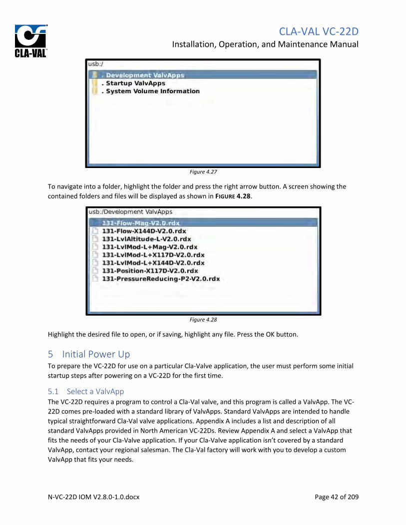
To navigate into a folder, highlight the folder and press the right arrow button. A screen showing the
contained folders and files will be displayed as shown in FIGURE 4.28.
Figure 4.28
Highlight the desired file to open, or if saving, highlight any file. Press the OK button.
5 Initial Power Up To prepare the VC-22D for use on a particular Cla-Valve application, the user must perform some initial
startup steps after powering on a VC-22D for the first time.
5.1 Select a ValvApp The VC-22D requires a program to control a Cla-Val valve, and this program is called a ValvApp. The VC-
22D comes pre-loaded with a standard library of ValvApps. Standard ValvApps are intended to handle
typical straightforward Cla-Val valve applications. Appendix A includes a list and description of all
standard ValvApps provided in North American VC-22Ds. Review Appendix A and select a ValvApp that
fits the needs of your Cla-Valve application. If your Cla-Valve application isn’t covered by a standard
ValvApp, contact your regional salesman. The Cla-Val factory will work with you to develop a custom
ValvApp that fits your needs.

CLA-VAL VC-22D
Installation, Operation, and Maintenance Manual
N-VC-22D IOM V2.8.0-1.0.docx Page 43 of 209
5.2 Load a ValvApp After selecting a ValvApp from the standard library or obtaining a custom ValvApp from the Cla-Val
factory, the ValvApp must be loaded into the VC-22D.
To load the ValvApp, follow the procedure below:
1. Power on the VC-22D for the first time and wait for the screen shown in FIGURE 5.1 to appear.
Figure 5.1

CLA-VAL VC-22D
Installation, Operation, and Maintenance Manual
N-VC-22D IOM V2.8.0-1.0.docx Page 44 of 209
1. If a standard ValvApp will be used, do the following:
a. Press “left” to load a ValvApp from the built-in library. Wait for the next screen and
highlight “North America” as shown in FIGURE 5.2. Press “OK”.
Figure 5.2
b. Highlight the desired ValvApp (131-LvlAltitude-L-V2.0 used for example) and press “OK”
as shown in FIGURE 5.3.
Figure 5.3

CLA-VAL VC-22D
Installation, Operation, and Maintenance Manual
N-VC-22D IOM V2.8.0-1.0.docx Page 45 of 209
c. When prompted for confirmation, highlight “Yes” using navigation arrows and press
“OK” as shown in FIGURE 5.4.
Figure 5.4
d. Press “OK” to restart per FIGURE 5.5.
Figure 5.5
2. If a custom ValvApp will be used, do the following:
a. Load the custom ValvApp provided by the Cla-Val factory onto a USB thumb drive.
b. Insert the USB thumb drive into the VC-22D’s USB port.

CLA-VAL VC-22D
Installation, Operation, and Maintenance Manual
N-VC-22D IOM V2.8.0-1.0.docx Page 46 of 209
c. Press “right” to load the ValvApp from the USB thumb drive. Wait for the next screen
and highlight the custom ValvApp (131-UpstreamPressure-CSTMR.v.1.0 used for
example) as shown in FIGURE 5.6. Press “OK”.
Figure 5.6
d. When prompted for confirmation, highlight “Yes” using navigation arrows and press
“OK” as shown in Figure 5.7.
Figure 5.7

CLA-VAL VC-22D
Installation, Operation, and Maintenance Manual
N-VC-22D IOM V2.8.0-1.0.docx Page 47 of 209
e. Press “OK” to restart per FIGURE 5.8.
Figure 5.8
5.3 Configuration Wizard Each time the VC-22D is rebooted, the user is prompted to go through the configuration wizard. The
configuration wizard allows the user to quickly configure the VC-22D settings for your specific Cla-Val
valve application. Settings include date and time, engineering units, and scale of inputs/outputs. The
wizard also includes prompts to test input/outputs and specify the normally open/closed state of
solenoids.
Going through the configuration wizard is optional and should only be used with the ValvApps from
the standard library. Unless instructed otherwise, do not go through the configuration wizard when
using a custom ValvApp. This is because settings have already been adjusted for you in the custom
ValvApp and changing these settings could conflict with custom programming.
A description of each configuration wizard screen is provided below.

CLA-VAL VC-22D
Installation, Operation, and Maintenance Manual
N-VC-22D IOM V2.8.0-1.0.docx Page 48 of 209
5.3.1 Introduction Screen Use this screen to enter the configuration wizard, skip the configuration wizard, or skip and prevent
from being prompted in the future.
Figure 5.9

CLA-VAL VC-22D
Installation, Operation, and Maintenance Manual
N-VC-22D IOM V2.8.0-1.0.docx Page 49 of 209
5.3.2 Warning Screen This is an alert to let you know the configuration wizard will change outputs which will likely modulate
the valve and affect other connected equipment. Be sure that the valve and other connected equipment
is in a safe state before continuing.
Configuration wizard will change the VC-22D outputs! To test outputs, the configuration wizard will change analog outputs from 4mA to 20mA and toggle digital outputs on/off. This will cause connected equipment to change state. It’s recommended that the cover on the Cla-Val valve be “locked” using the isolation ball valves before continuing. Take necessary precautions for other connected equipment.
Figure 5.10
DANGER

CLA-VAL VC-22D
Installation, Operation, and Maintenance Manual
N-VC-22D IOM V2.8.0-1.0.docx Page 50 of 209
5.3.3 Regional Settings The regional settings allow you to specify location, time zone, and language.
Figure 5.11
5.3.4 Inputs The setup wizard will dedicate one screen to each input configured in the ValvApp. An example screen
for an analog input is shown in FIGURE 5.12. The analog input screen can be used to set the 4-20mA
scaling, verify the value currently read by the analog input, and what to do if the signal is lost. See
section 6.2.9.4 for a detailed description of signal lost behaviors.
Figure 5.12
The digital input screens can be used to verify the value currently read by a digital input. An example is
shown in FIGURE 5.13.

CLA-VAL VC-22D
Installation, Operation, and Maintenance Manual
N-VC-22D IOM V2.8.0-1.0.docx Page 51 of 209
Figure 5.13
5.3.5 Outputs The setup wizard has two screens for each analog output configured in the ValvApp. The first screen is
used for adjusting the 4-20mA scaling as shown in FIGURE 5.14.
Figure 5.14
The second screen is used for testing the analog output as shown in FIGURE 5.15. This screen allows an
analog output value to be forced and checked with a multimeter for verification.

CLA-VAL VC-22D
Installation, Operation, and Maintenance Manual
N-VC-22D IOM V2.8.0-1.0.docx Page 52 of 209
Figure 5.15
The setup wizard also has one screen for each digital output configured in the ValvApp as shown in
FIGURE 5.16. This screen allows you to toggle the digital output on/off which is helpful when verifying
solenoid wiring. When the SO1 output is being tested, the closing solenoid should be clicking
open/closed. When the SO2 output is being tested, the opening solenoid should be clicking open/closed.
The same test is available for RO1 and RO2 which could be connected to AC solenoids or some other
equipment.
Figure 5.16
5.3.6 Solenoid Configuration The solenoid configuration screen allows the user to input whether the solenoids are normally opened
or normally closed as shown in FIGURE 5.17. The VC-22D needs to know the normal state of the solenoid
so the PID algorithm understands whether voltage will open or close the solenoid. “NC” means normally
closed, and “NO” means normally open. The first two characters before the slash represent the closing

CLA-VAL VC-22D
Installation, Operation, and Maintenance Manual
N-VC-22D IOM V2.8.0-1.0.docx Page 53 of 209
solenoid SO1 normal state, and the second two characters after the slash represent the opening
solenoid SO2 normal state.
Figure 5.17
5.3.7 DP Metering If the ValvApp has DP metering enabled, there will be two screens available to configure DP metering
settings. The first screen shown in FIGURE 5.18 is used to input the valve size, body, and seat type so
flow rate can be calculated.
Figure 5.18
The second screen allows the user to specify which variables represent the inlet/outlet pressure and
valve position for calculating valve flow. See FIGURE 5.19.

CLA-VAL VC-22D
Installation, Operation, and Maintenance Manual
N-VC-22D IOM V2.8.0-1.0.docx Page 54 of 209
Figure 5.19
For more detailed information on the configuration of DP metering, see section 6.2.1.
5.3.8 Hostname The hostname screen allows the user to entry a user-friendly name for the VC-22D which will be used in
log files and displayed on the bottom left hand corner of each screen. It’s recommended to input a
name that uniquely describes the valve being controlled. This is helpful for users so they’re aware of
which valve is being controlled by the VC-22D.
Figure 5.20

CLA-VAL VC-22D
Installation, Operation, and Maintenance Manual
N-VC-22D IOM V2.8.0-1.0.docx Page 55 of 209
6 Setup The VC-22D’s settings are broken into the following four categories:
1. System settings: Accessible via “long down” from the home screen.
2. Valve control settings: Accessible via “long up” from the home screen.
3. Input settings: Accessible via “long left” from the home screen.
4. Output settings: Accessible via “long right” from the home screen.
6.1 System Settings System settings pertain to the VC-22D’s administration. Examples of system settings are time/date, IP
address, display brightness, and data logging. These settings do not directly influence the way the valve
is controlled, but impact how the VC-22D functions.
6.1.1 VC-22D Information
6.1.1.1 Description
Provides identification information (serial numbers and owner information), version information, system
statistics (runtime), and list of pre-loaded ValvApp libraries
6.1.1.2 Navigation Path
1. Start at the home screen
2. Long down
3. Click on “Information”
6.1.1.3 Identification Tab Settings
Figure 6.1
S/N (IMEI): Serial number of the VC-22D assigned by Cla-Val during manufacture of device.
SIM (ICCID): ID number of SIM card installed in VC-22D.
Hostname: Name specified by user of VC-22D that is displayed on bottom left hand corner of every
screen and included in log files. It’s recommended to input a name that uniquely describes the valve

CLA-VAL VC-22D
Installation, Operation, and Maintenance Manual
N-VC-22D IOM V2.8.0-1.0.docx Page 56 of 209
being controlled. This is helpful for users so they’re aware of which valve is being controlled by the VC-
22D.
Contact: Optional setting to specify name of person to contact in case of service related issue with valve.
Location: Optional setting to specify location valve is installed.
Order ID: Optional setting to specify ID of order placed to obtain VC-22D. This may be useful when an
operator is calling for support on the unit.
6.1.1.4 Version Tab Settings
Figure 6.2
Engine: Version of engine (sometimes called firmware) that is installed on the VC-22D. The engine is
responsible for running the ValvApp loaded onto the VC-22D. It controls what features are available for
the ValvApp to utilize. Prior to configuring a new VC-22D, ensure the latest engine version is installed.
Contact your local sales rep for a copy of the latest engine. See section 6.1.20 for an engine update
procedure.
Kernel: Version of kernel that is installed on the VC-22D. The kernel is responsible for managing events
in the VC-22D. Prior to configuring a new VC-22D, ensure the latest kernel version is installed. Contact
your local sales rep for a copy of the latest kernel. See section 6.1.23 for an engine update procedure.
R-Loader md5: Version of software that launches the engine upon VC-22D startup.
Modem: Provides the model number of the cellular modem in the VC-22D. Also provides the version of
firmware installed on the modem.
Microchip: Version of the microcontroller responsible for reading and writing to IO terminals.

CLA-VAL VC-22D
Installation, Operation, and Maintenance Manual
N-VC-22D IOM V2.8.0-1.0.docx Page 57 of 209
6.1.1.5 System Info Tab Settings
Figure 6.3
Uptime: Duration of time the VC-22D has been powered on since last shutdown.
Load average: The Unix style load average of the CPU at 1 minute, 5 minutes, and 15 minutes after the
system started.
RAM usage: Amount of RAM used, amount of RAM free
6.1.1.6 Libraries Settings
Figure 6.4
The libraries tab shows all of the ValvApps that have been loaded onto the VC-22D. This includes
standard ValvApps (located in the EMEA and North America folders) along with custom ValvApps that
have been previously uploaded. If a factory reset is performed, the ValvApps shown in this tab can be

CLA-VAL VC-22D
Installation, Operation, and Maintenance Manual
N-VC-22D IOM V2.8.0-1.0.docx Page 58 of 209
reloaded into the VC-22D if you follow the instructions listed in section “5.2 Load a ValvApp” and “load
from library”.
6.1.2 ValvApp Backup
6.1.2.1 Description
Used to schedule automatic backups or take manual backups of the currently loaded ValvApp and store
in internal memory.
6.1.2.2 Navigation Path
1. Start at the home screen
2. Long down
3. Click on “Application Management”
4. Click on “Backup Application”
6.1.2.3 Backup Application Settings
Figure 6.5
Backup Now: Clicking this button will trigger an immediate backup of the ValvApp currently running on
the VC-22D. The backup will be stored in the VC-22D’s non-volatile internal memory. Backups in internal
memory can be restored later if necessary. See section 6.1.3.
Automatically back up locally every day at 23:45: Checking this box will automatically backup the
ValvApp currently running on the VC-22D at 11:45PM every night. The backup will be stored in the VC-
22D’s non-volatile internal memory.
Automatically back up to FTP server at 23:45 if the ValvApp has been changed: This box is not
applicable in North America, as it requires an FTP connection to Link2Valve. This is a European feature
only.

CLA-VAL VC-22D
Installation, Operation, and Maintenance Manual
N-VC-22D IOM V2.8.0-1.0.docx Page 59 of 209
6.1.3 Restore Application
6.1.3.1 Description
Used to restore an application that’s been backed up per section 6.1.2 to the VC-22D’s internal memory.
The restored application automatically becomes the currently running ValvApp.
6.1.3.2 Navigation Path
1. Start at the home screen
2. Long down
3. Click on “Application Management”
4. Click on “Restore Application”
6.1.3.3 Restore Application Settings
Figure 6.6
Each ValvApp backup is prefixed with a date when the backup was taken. Find the date you wish to
rollback too, highlight the corresponding file, and press “OK”. After answering yes to confirmation
prompts, the VC-22D will reboot and restore the selected ValvApp.
6.1.4 Export Application
6.1.4.1 Description
Exports the currently loaded ValvApp onto a USB thumb drive inserted in the VC-22D’s USB port.
6.1.4.2 Navigation Path
1. Start at the home screen
2. Long down
3. Click on “Application Management”
4. Click on “Export Application”

CLA-VAL VC-22D
Installation, Operation, and Maintenance Manual
N-VC-22D IOM V2.8.0-1.0.docx Page 60 of 209
6.1.4.3 Export Application Settings
Figure 6.7
USB: Highlighting USB and pressing “OK” will allow the currently loaded ValvApp to be exported to a
USB thumb drive inserted in the VC-22D’s USB port. The screen shown in FIGURE 6.8 will appear.
Figure 6.8
The screen in FIGURE 6.8 shows the contents saved on the inserted USB thumb drive and allows the user
to save the ValvApp in a particular folder. In this example the thumb drive has a “Development
ValvApps” folder and “Startup ValvApps” folder. The “System Volume Information” folder is a hidden file
on the thumb drive which should be ignored. To navigate into a folder, highlight the folder and press the
“right” navigation button. Once located in the desired folder, pressing the “OK” navigation button will
export the ValvApp to the current location.

CLA-VAL VC-22D
Installation, Operation, and Maintenance Manual
N-VC-22D IOM V2.8.0-1.0.docx Page 61 of 209
My FTP: This box is not applicable in North America, as it requires an FTP connection to Link2Valve. This
is a European feature only.
6.1.5 Import Application
6.1.5.1 Description
Imports a ValvApp saved from an inserted USB thumb drive.
6.1.5.2 Navigation Path
1. Start at the home screen
2. Long down
3. Click on “Application Management”
4. Click on “Import Application”
6.1.5.3 Import Application Settings
Figure 6.9

CLA-VAL VC-22D
Installation, Operation, and Maintenance Manual
N-VC-22D IOM V2.8.0-1.0.docx Page 62 of 209
Pressing “OK” with “USB” highlighted will open the screen shown in FIGURE 6.10. This screen shows the
contents saved on the USB thumb drive. Navigate to the folder the ValvApp is stored in by highlighting
the folder and pressing the “right” navigation button. Once in the correct folder, highlight the ValvApp
and press “OK”. After saying yes to confirmation prompts, the ValvApp will be imported and the VC-22D
will be rebooted.
Figure 6.10
6.1.6 Time & Region
6.1.6.1 Description
Used to set the VC-22D’s clock, date, time zone, and language
6.1.6.2 Navigation Path
1. Start at the home screen
2. Long down
3. Click on “Time & Region”

CLA-VAL VC-22D
Installation, Operation, and Maintenance Manual
N-VC-22D IOM V2.8.0-1.0.docx Page 63 of 209
6.1.6.3 Time Zone Tab Settings
Figure 6.11
Use UTC on this system: If checked, the VC-22D clock will operate on UTC time and not allow a local
time zone to be entered.
Region: Stores the region the VC-22D is located in. This determines which time zones may be selected in
the “Time Zone” field. Regions available are listed below:
1. Africa
2. Americas (refers South America only)
3. Asia
4. Europe
5. Middle East
6. North America
7. Oceania
Time Zone: Stores the time zone the VC-22D is located in. The following time zones are available for
North America. In some cases, there are multiple time zones for the same hours difference from GMT.
This is because different time zones have different day light savings rules, so be sure to select the
appropriate location in addition to difference from GMT.
1. (GMT-09:00) Alaska
2. (GMT-08:00) Pacific Time (US & Canada)
3. (GMT-07:00) Mountain Tim (US & Canada)
4. (GMT-07:00) Chihuahua, La Pax, Mazatlan
5. (GMT-07:00) Arizona
6. (GMT-06:00) Saskatchewan
7. (GMT-06:00) Guadalajara, Mexico City
8. (GMT-06:00) Central Time (US & Canada)
9. (GMT-05:00) Quintana Roo, Mexico

CLA-VAL VC-22D
Installation, Operation, and Maintenance Manual
N-VC-22D IOM V2.8.0-1.0.docx Page 64 of 209
10. (GMT-05:00) Eastern Time (US & Canada)
11. (GMT-04:00) Atlantic Time (Canada)
12. (GMT-03:00) Newfoundland
Automatically adjust for Daylight Saving Time: The VC-22D has been programmed with the daylight
savings calendar for each time zone listed above. If this box is checked, the VC-22D will use the built-in
calendar to shift the system clock 1 hour for daylight savings.
6.1.6.4 Date/Time Tab Settings
Figure 6.12
Date: Specifies the VC-22D’s system date.
Time: Specifies the VC-22D’s system time.
Use NTP for automatic time updates: This box is not applicable in North America, as it requires an NTP
connection to Link2Valve. This is a European feature only.
NTP server: Specifies an NTP server to have the VC-22D synchronize time with.
Manual NTP sync: (see FIGURE 6.13) If clicked, this button forces the VC-22D to immediately synchronize
time the specified NTP server.
Figure 6.13

CLA-VAL VC-22D
Installation, Operation, and Maintenance Manual
N-VC-22D IOM V2.8.0-1.0.docx Page 65 of 209
6.1.6.5 Language Tab Settings
Figure 6.14
Date/Time Format: Specify the style of Date/Time format that’s preferred. The following options exist:
1. USA (MM/DD/YY 12hr (am/pm)
2. UK & Europe (DD/MM/YY 24hr)
UI Language: Specify the language used on the user interface. Options are listed below:
1. English
2. Spanish
3. French
Import Language Pack: (see FIGURE 6.15) If clicked, a language pack from a USB thumb drive can be
imported which allows a language not included above to be implemented on the user interface.
Figure 6.15
6.1.7 Unit Management
6.1.7.1 Description
Used to specify the engineering units for each unit type (e.g. pressure, flow, volume, …) in the VC-22D.
This forces the same engineering unit to be applied for a given value type (e.g. all pressure values are in
psi, all flow is in gpm, all volume is in gallons, …). Going through unit management should only be done
with the ValvApps from the standard library. Unless instructed otherwise, do not go through the
configuration wizard when using a custom ValvApp. This is because settings have already been
adjusted for you in the custom ValvApp, and changing these settings could conflict with custom
programming.

CLA-VAL VC-22D
Installation, Operation, and Maintenance Manual
N-VC-22D IOM V2.8.0-1.0.docx Page 66 of 209
6.1.7.2 Unit Management Settings
Figure 6.16
Each unit type (pressure, flow, volume, …) that the VC-22D supports is listed on the unit management
screen in the left-hand column. The right-hand column specifies the engineering unit associated with the
corresponding unit type. To allow different units for a given unit type, set the unit to “Any”. To force a
given unit type to a particular unit, select the desired unit.
6.1.8 Configure Logs
6.1.8.1 Description
Used to enable/disable periodic logging of variable values and specify frequency of logging.
6.1.8.2 Navigation Path
1. Start at the home screen
2. Long down
3. Click on “Logging”
4. Click on “Configuration”

CLA-VAL VC-22D
Installation, Operation, and Maintenance Manual
N-VC-22D IOM V2.8.0-1.0.docx Page 67 of 209
6.1.8.3 Logging Configuration Settings
Figure 6.17
Logging enabled: When checked, the VC-22D will write every variable value to a CSV file in memory at
the specified logging interval.
Log interval: The number of minutes the VC-22D waits before logging variable values again.
FTP Transfer interval: This setting is not applicable in North America, as it requires an FTP connection to
Link2Valve. This is a European feature only.
Log format: Specifies the format of the CSV file the VC-22D will create when logging data. There are two
options available:
1. Legacy
2. V 1.0
It’s recommended to always use V 1.0 because it provides more information than the legacy format. Do
not use legacy unless requested by Cla-Val.
6.1.9 Export Logs
6.1.9.1 Description
Used to export a log file of variable values and a system log file detailing actions, errors, and warnings
stored by the VC-22D.
6.1.9.2 Navigation Path
1. Start at the home screen
2. Long down
3. Click on “Logging”
4. Click on “Export”

CLA-VAL VC-22D
Installation, Operation, and Maintenance Manual
N-VC-22D IOM V2.8.0-1.0.docx Page 68 of 209
6.1.9.3 Export Settings
Figure 6.18
This screen specifies how far back in time the exported log files will go. After selecting a duration option,
pressing the “OK” button or clicking the right arrow brings up a file explorer which specifies where on
the USB thumb drive the log files will be saved.
6.1.10 GSM/GPRS
6.1.10.1 Description
This setting is not applicable in North America, as it pertains to a cellular connection. This is a European
feature only.
6.1.11 LAN
6.1.11.1 Description
Used to set the IP address, subnet mask, DNS IP address, and gateway address for the VC-22D.
6.1.11.2 Navigation Path
1. Start at the home screen
2. Long down
3. Click on “Connectivity”
4. Click on “LAN”

CLA-VAL VC-22D
Installation, Operation, and Maintenance Manual
N-VC-22D IOM V2.8.0-1.0.docx Page 69 of 209
6.1.11.3 LAN Settings
Figure 6.19
IP Address: TCP/IP address of the VC-22D
Subnet mask: Subnet mask of the TCP/IP address
DNS IP address: Address of the DNS server the VC-22D sends requests too
Gateway address: Address of the gateway the VC-22D sends network traffic too that is not on the VC-
22D’s subnet
6.1.12 Remote Recopy
6.1.12.1 Description
This setting is not applicable in North America, as it requires a cellular connection. This is a European
feature only.
6.1.13 Modbus
6.1.13.1 Description
Used to configure Modbus communication parameters for Modbus TCP/IP, Modbus RS485, and Modbus
RS232. Also provides a register map for internal variables.
6.1.13.2 Navigation Path
1. Start at the home screen
2. Long down
3. Click on “Connectivity”
4. Click on “Modbus”

CLA-VAL VC-22D
Installation, Operation, and Maintenance Manual
N-VC-22D IOM V2.8.0-1.0.docx Page 70 of 209
6.1.13.3 General Tab Settings
Figure 6.20
Modbus I/O mapping scheme: Specifies whether the VC-22D will use “Standard” or “Cla-Val” Modbus
register mapping. “Standard” was introduced in engine 2.5.0 and is the recommend scheme. “Cla-Val”
has been left for backwards compatibility. See section 9 for a detailed description of each scheme.
Modbus TCP/IP enabled: Allows VC-22D to receive and respond to Modbus TCP/IP requests.
Modbus RS485 enabled: Allows VC-22D to receive and respond to Modbus RS485 requests.
Modbus RS232 enabled: Allows VC-22D to receive and respond to Modbus RS485 requests.
6.1.13.4 TCP/IP Tab Settings
Figure 6.21
Modbus TCP/IP enabled: Allows VC-22D to receive and respond to Modbus TCP/IP requests.

CLA-VAL VC-22D
Installation, Operation, and Maintenance Manual
N-VC-22D IOM V2.8.0-1.0.docx Page 71 of 209
IP Port No: Displays the port that the VC-22D listens for Modbus TCP/IP requests on. This is not user
adjustable. Devices communicating to VC-22D must always use port 502.
Allowed Client: Specifies which devices the VC-22D is allowed to listen and respond too via Modbus
TCP/IP. This is to prevent unauthorized devices from communicating with VC-22D. The dropdown has
three options:
1. All: The VC-22D will respond to Modbus requests from any device.
2. IP Range: The VC-22D will only respond to Modbus requests that come from devices with an IP
address in a specified range. If this option is selected, a text box appears below the setting
allowing the user to enter the allowed IP address range as shown in FIGURE 6.22.
Figure 6.22
3. Single Client: The VC-22D will only respond to Modbus requests that come from a device with a
user specified IP address. If this option is selected, a text box appears below the setting allowing
the user to enter the allowed IP address as shown in FIGURE 6.23.
Figure 6.23
Allowed Interface: Specifies which physical connection the VC-22D will listen for Modbus requests on.
This is to further prevent unauthorized access by restricting the number of communication pathways
into the VC-22D. The dropdown has three options:
1. All: The VC-22D will listen to and respond to Modbus TCP/IP requests from the cell modem and
Ethernet port.
2. Ethernet: The VC-22D will listen to and respond to Modbus TCP/IP requests from the Ethernet
port only. Requests coming in through the cell modem will be ignored.
3. GPRS: The VC-22D will listen to and respond to Modbus TCP/IP requests from the cell modem
only. Requests coming in through the Ethernet port will be ignored. This is a European feature
only, as the cell modem is not operational in North America.
Override Timeout (sec): The number of seconds the VC-22D will wait without receiving a Modbus TCP/IP
request before clearing all Modbus overrides and reverting registers back to original values. See section
9 for more information on the Modbus override. A value of 0 will disable the Override Timeout
functionality.
IEEE Float word order: Specifies if the first word in a two word IEEE 754 float is the high ordered word
(MSW) or the low ordered word (LSW). This specifies the register “endianness” for IEEE 754 encoded
registers.

CLA-VAL VC-22D
Installation, Operation, and Maintenance Manual
N-VC-22D IOM V2.8.0-1.0.docx Page 72 of 209
6.1.13.5 RS485 Tab Settings
Figure 6.24
Modbus RS485 enabled: Allows VC-22D to receive and respond to Modbus RS485 requests.
Modbus Address: Address that the VC-22D responds to Modbus RS485 requests on.
Line Speed (baud): Baud rate of the VC-22D’s RS485 interface. Options are 4800, 9600, 19200, 38400,
57600, and 115200. Note, the VC-22D uses 8 data bits, no parity, 1 stop bit, and no flow control for the
remainder of the RS485 serial settings.
Override Timeout (sec): The number of seconds the VC-22D will wait without receiving a Modbus RS485
request before clearing all Modbus overrides and reverting registers back to original values. See section
9 for more information on the Modbus override. A value of 0 will disable the Override Timeout
functionality.
IEEE Float word order: Specifies if the first register in a two register IEEE 754 float is the high ordered
byte (MSW) or the low ordered byte (LSW). This specifies the register “endianness” for IEEE 754
encoded registers.
Run as Modbus master: When checked, this switches the Modbus RS485 from a server to a client. This is
only used when the VC-22D is connected to other Cla-Val products (like the 34 series actuator) via
Modbus RS485.

CLA-VAL VC-22D
Installation, Operation, and Maintenance Manual
N-VC-22D IOM V2.8.0-1.0.docx Page 73 of 209
6.1.13.6 RS232 Tab Settings
Figure 6.25
Modbus RS232 enabled: Allows VC-22D to receive and respond to Modbus RS232 requests.
Modbus Address: Address that the VC-22D responds to Modbus RS232 requests on.
Line Speed (baud): Baud rate of the VC-22D’s RS232 interface. Options are 4800, 9600, 19200, 38400,
57600, and 115200.
Override Timeout (sec): The number of seconds the VC-22D will wait without receiving a Modbus RS485
request before clearing all Modbus overrides and reverting registers back to original values. See section
9 for more information on the Modbus override. A value of 0 will turn off the Override Timeout
functionality.
Flow Control: Enables or disables hardware level RTS/CTS hardware control. Note, the VC-22D uses 8
data bits, no parity, and 1 stop bit for the remainder of the RS232 serial settings.
IEEE Float word order: Specifies if the first register in a two register IEEE 754 float is the high ordered
byte (MSW) or the low ordered byte (LSW). This specifies the register “endianness” for IEEE 754
encoded registers.

CLA-VAL VC-22D
Installation, Operation, and Maintenance Manual
N-VC-22D IOM V2.8.0-1.0.docx Page 74 of 209
6.1.13.7 Variable Map
Figure 6.26
The variable provides a read only view of the VC-22Ds variables and corresponding Modbus addresses.
Each variable gets a Modbus address in the three Modbus blocks (see section 9 for more information on
Modbus blocks). The minimum and maximum value of each variable is also displayed.
6.1.14 Remote Access
6.1.14.1 Description
Used to enable/disable the VNC protocol to the VC-22D. The VNC protocol allows a remote computer
(Windows or Linux) to view the VC-22D’s display and click buttons on it. This is very similar to
Microsoft’s Remote Desktop protocol.
6.1.14.2 Navigation Path
1. Start at the home screen
2. Long down
3. Click on “Connectivity”
4. Click on “Remote Access”

CLA-VAL VC-22D
Installation, Operation, and Maintenance Manual
N-VC-22D IOM V2.8.0-1.0.docx Page 75 of 209
6.1.14.3 Remote Access Settings
Figure 6.27
VNC enabled: Allows communication to the VC-22D via the VNC protocol.
IP Port No: Specifies the port number the VC-22D listens for VNC traffic on. This port number is fixed at
5900 and cannot be changed by the user.
Password: The password required when establishing a VNC connection to the VC-22D.
Allowed Client: Specifies which devices the VC-22D is allowed to listen and respond too via VNC. This is
to prevent unauthorized devices from communicating with VC-22D. The dropdown has three options:
1. All: The VC-22D will respond to VNC requests from any device.
2. IP Range: The VC-22D will only respond to VNC requests that come from devices with an IP
address in a specified range. If this option is selected, a text box appears below the setting
allowing the user to enter the allowed IP address range as shown in FIGURE 6.28.
Figure 6.28
3. Single Client: The VC-22D will only respond to VNC requests that come from a device with a user
specified IP address. If this option is selected, a text box appears below the setting allowing the
user to enter the allowed IP address as shown in FIGURE 6.29.
Figure 6.29

CLA-VAL VC-22D
Installation, Operation, and Maintenance Manual
N-VC-22D IOM V2.8.0-1.0.docx Page 76 of 209
Allowed Interface: Specifies which physical connection the VC-22D will listen for Modbus requests on.
This is to further prevent unauthorized access by restricting the number of communication pathways
into the VC-22D. The dropdown has three options:
1. All: The VC-22D will listen to and respond to Modbus TCP/IP requests from the cell modem and
Ethernet port.
2. Ethernet: The VC-22D will listen to and respond to Modbus TCP/IP requests from the Ethernet
port only. Requests coming in through the cell modem will be ignored.
3. GPRS: The VC-22D will listen to and respond to Modbus TCP/IP requests from the cell modem
only. Requests coming in through the Ethernet port will be ignored. This is a European feature
only, as the cell modem is not operational in North America.
6.1.15 Cloud Storage
6.1.15.1 Description
This setting is not applicable in North America, as it requires a cellular connection. This is a European
feature only.
6.1.16 Wireless
6.1.16.1 Description
This setting allows the user to control a wireless LAN that may be broadcasted from the VC-22D with the
use of a USB WiFi adapter. The wireless LAN capability has been provided to make on-site support more
user friendly. It eliminates the need for a long Ethernet cable or using a laptop in a confined space.
To obtain a USB WiFi adapter for the VC-22D, contact your local Cla-Val sales representative. While
there are many USB WiFi adapters available on the market, it’s best to obtain one from Cla-Val to ensure
the WiFi adapter is compatible with the VC-22D.
The wireless setting will not be visible in the system settings unless the VC-22D was booted with a USB
WiFi adapter already plugged in. To ensure the wireless setting is visible, insert the USB WiFi adapter
into the VC-22D’s USB port, and then, perform a reboot of the VC-22D.
6.1.16.2 Navigation Path
1. Start at the home screen
2. Long down
3. Click on “Connectivity”
4. Click on “Wireless”

CLA-VAL VC-22D
Installation, Operation, and Maintenance Manual
N-VC-22D IOM V2.8.0-1.0.docx Page 77 of 209
6.1.16.3 Wireless Settings
Figure 6.30
WiFi Enabled: Checking this box will allow the VC-22D to broadcast the WiFi signal. If this box is
unchecked, the signal will not be broadcast.
WiFi AP Name: Displays the name of the WiFi LAN that will be displayed to other computers browsing
local WiFi networks.
WPA Key: Displays the passcode that’s required for another computer to join the WiFi LAN.
IP Address: Displays the IP address of the VC-22D on the WiFi network.
6.1.17 Web Interface
6.1.17.1 Description
Used to enable/disable the web interface for the VC-22D which allows for remote upload/download of
files to the VC-22D via a web browser.
6.1.17.2 Navigation Path
1. Start at the home screen
2. Long down
3. Click on “Connectivity”
4. Click on “Web Interface”

CLA-VAL VC-22D
Installation, Operation, and Maintenance Manual
N-VC-22D IOM V2.8.0-1.0.docx Page 78 of 209
6.1.17.3 Web Interface Settings
Figure 6.31
Web interface enabled: Checking this box enables the web interface
URL Ethernet: Lists the URL to use for accessing the web interface from a browser
6.1.18 Security
6.1.18.1 Description
Allows the user to specify a password that must be entered to obtain access to critical settings.
6.1.18.2 Navigation Path
1. Start at the home screen
2. Long down
3. Click on “Security”

CLA-VAL VC-22D
Installation, Operation, and Maintenance Manual
N-VC-22D IOM V2.8.0-1.0.docx Page 79 of 209
6.1.18.3 Security Settings
Figure 6.32
This screen allows the user to specify a log in password. By default, no password is set and the user is
always considered logged in. After specifying a password, the user will be prompted to login with the
password before accessing any of the following screens:
1. System settings (long down)
2. Valve control settings (long up)
3. Input settings (long left)
4. Output settings (long right)
Once logged in, the user will remain logged in until 20 minutes of inactivity. The login status is depicted
with a padlock icon on the top bar of the VC-22D’s display (see FIGURE 6.33 below):
Figure 6.33
To remove the password, go to the security settings and enter “000000” as the password.
6.1.19 Reboot
6.1.19.1 Description
Reboots the VC-22D.
6.1.19.2 Navigation Path
1. Start from the home screen
2. Long down
3. Click on “Reboot”

CLA-VAL VC-22D
Installation, Operation, and Maintenance Manual
N-VC-22D IOM V2.8.0-1.0.docx Page 80 of 209
6.1.19.3 Reboot Settings
Figure 6.34
The reboot screen will ask for confirmation before initiating the reboot. If you press the left navigation
button, the reboot is cancelled. If you press the OK navigation button, the VC-22D is rebooted.
6.1.20 Engine Update
6.1.20.1 Description
Used to update the engine software on the VC-22D.
6.1.20.2 Navigation Path
1. Start at the home screen
2. Long down
3. Click on “Advanced”
4. Click on “Engine Update”

CLA-VAL VC-22D
Installation, Operation, and Maintenance Manual
N-VC-22D IOM V2.8.0-1.0.docx Page 81 of 209
6.1.20.3 Engine Update Settings
Figure 6.35
The engine update screen shows a file explorer which can be used to navigate to an engine update file.
Selecting an engine update file and pressing “OK” will prompt for confirmation. Saying yes to the
confirmations will update the engine and reboot the VC-22D.
6.1.21 Diagnostics to USB
6.1.21.1 Description
Used to export log files about the VC-22Ds errors and warnings to a USB thumb drive.
6.1.21.2 Navigation Path
1. Start at the home screen
2. Long down
3. Click on “Advanced”
4. Click on “Diag->USB”

CLA-VAL VC-22D
Installation, Operation, and Maintenance Manual
N-VC-22D IOM V2.8.0-1.0.docx Page 82 of 209
6.1.21.3 Diagnostics to USB Settings
Figure 6.36
The diagnostics to USB screen shows a file explorer that allows the user to select a location to export
diagnostic files too. The diagnostic files will include traces of software faults that have occurred.
6.1.22 Factory Reset
6.1.22.1 Description
Used to remove the currently running ValvApp and return all settings in the VC-22D to factory default.
The VC-22D will require a new ValvApp to be loaded before it is operational again.
6.1.22.2 Navigation Path
1. Start at the home screen
2. Long down
3. Click on “Advanced”
4. Click on “Factory Reset”
6.1.22.3 Factory Reset Settings
Figure 6.37
The factory reset screen is just a confirmation prompt. Clicking “Yes” will revert the VC-22D back to its
factory default state and reboot the controller. Clicking “No” will cancel the factory reset.

CLA-VAL VC-22D
Installation, Operation, and Maintenance Manual
N-VC-22D IOM V2.8.0-1.0.docx Page 83 of 209
6.1.23 Kernel Update
6.1.23.1 Description
Used to update the VC-22D’s kernel software.
6.1.23.2 Navigation Path
1. Start at the home screen
2. Long down
3. Click on “Advanced”
4. Click on “Kernel Update”
6.1.23.3 Kernel Update Settings
Figure 6.38
The kernel update screen shows a file explorer which can be used to navigate to a kernel update file.
Selecting a kernel update file and pressing “OK” will prompt for confirmation. Saying yes to the
confirmations will update the kernel and reboot the VC-22D.
6.1.24 Configuration Wizard
6.1.24.1 Description
Launches the configuration wizard. See section 5.3 for more information about the configuration wizard.
6.1.24.2 Navigation Path
1. Start at the home screen
2. Long down
3. Click on “Advanced”
4. Click on “Configuration Wizard”

CLA-VAL VC-22D
Installation, Operation, and Maintenance Manual
N-VC-22D IOM V2.8.0-1.0.docx Page 84 of 209
6.1.24.3 Configuration Wizard Settings
Figure 6.39
The configuration wizard icon opens a prompt which allows the user to run the configuration wizard.
6.1.25 Display Brightness
6.1.25.1 Description
Allows the user to adjust the backlighting on the VC-22D display.
6.1.25.2 Navigation Path
1. Start at the home screen
2. Long down
3. Click on “Display”
4. Click on “Brightness”
6.1.25.3 Display Brightness Settings
Figure 6.40
The display brightness screen has a single percentage value. Setting 100% increases the display to
maximum brightness, setting 0% decreases the display to minimum brightness.
6.1.26 Shutoff Screen
6.1.26.1 Description
Allows the user to specify how long the screen remains on after no navigation keys have been pressed.

CLA-VAL VC-22D
Installation, Operation, and Maintenance Manual
N-VC-22D IOM V2.8.0-1.0.docx Page 85 of 209
6.1.26.2 Navigation Path
1. Start at the home screen
2. Long down
3. Click on “Display”
4. Click on “Shutoff”
6.1.26.3 Shutoff Screen Settings
Figure 6.41
The shutoff screen setting specifies how long the screen will remain on after no navigation keys have
been pressed. Setting this value to 0 forces it to remain on indefinitely. By default, the setting is 0.
6.2 Valve Control Settings Valve control settings impact how the VC-22D operates the valve. Examples of valve control settings are
PID gains, actions that trigger outputs based on inputs, and retransmission of input signals.
6.2.1 DP Metering
6.2.1.1 Description
Cla-Val has “CV-Lift” data on our valves which allows the flow rate through the valve to be calculated
based on pressure differential and valve position. The “CV-Lift” data changes based on valve size, valve
shape, flow direction, and seat type (standard or anti-cavitation).
The VC-22D comes with a preloaded library of CV-Lift data for the most common valves. The DP
metering settings allow the user to specify which “CV-Lift” data to use (based on valve size, valve shape,
and seat type). It also allows the user to specify which IO points are monitoring pressure differential and
valve position.
The DP metering is only enabled in certain ValvApps and cannot be enabled by the user. The user must
choose a ValvApp from the standard library that has DP metering enabled or contact a Cla-Val
representative to get a custom ValvApp.

CLA-VAL VC-22D
Installation, Operation, and Maintenance Manual
N-VC-22D IOM V2.8.0-1.0.docx Page 86 of 209
6.2.1.2 Navigation Path
1. Start at the home screen
2. Long up
3. Click on “DP Metering”
6.2.1.3 General Tab Settings
Figure 6.42
Metering DP description: Field to enter a user-friendly description of the DP metering function.
DP Table: Specifies which library the “CV-Lift” data will come from. The options are listed below:
1. EMEA: Allows “CV-Lift” data for European valve sizes to be selected on the next tab
2. North America: Allows “CV-Lift” data for our North American valve sizes to be selected on the
next tab.
3. Specific: Allows “CV-Lift” data to be selected for custom valves that have been specially loaded
into a custom ValvApp per customer request.

CLA-VAL VC-22D
Installation, Operation, and Maintenance Manual
N-VC-22D IOM V2.8.0-1.0.docx Page 87 of 209
6.2.1.4 Valve Tab Settings
Figure 6.43
Size: Specifies the valve size. Includes all common valve sizes for Cla-Valve.
Body Style: Specifies the body style. The options are 100-01 (Full Port Globe Valve) and 100-20 (Reduce
Port Globe Valve)
Seat Type: Specifies the seat type. In the standard library of “CV-Lift” data, only the standard seat type is
available.
DP Config: Specifies whether the pressure is measured at the valve’s boss inspection ports or the pipes
inspection ports.
6.2.1.5 Input Tab Settings
Figure 6.44

CLA-VAL VC-22D
Installation, Operation, and Maintenance Manual
N-VC-22D IOM V2.8.0-1.0.docx Page 88 of 209
Source: Specifies the analog input or interactive variable that reports the valve’s position.
P1 or DP: Specifies the analog input or interactive variable that reports the valve’s upstream pressure or
the differential pressure (inlet pressure – outlet pressure). If the source chosen is a differential pressure,
leave the “P2” setting blank.
P2: Specifies the analog input or interactive variable that has the valve’s downstream pressure. Leave
this field blank if a differential pressure (inlet pressure – outlet pressure) is specified in “P1”.
Differential Pressure: Displays the differential pressure being calculated from the “P1 or DP” and “P2”
sources.
6.2.1.6 Output Tab Settings
Figure 6.45
Output: Specifies the analog output or interactive variable that DP metering writes calculated flow too.
Default Value: Specifies the calculated flow that’s outputted when the valve position or pressure values
are out of range (i.e. the input wiring is disconnected).
Current Flow: Displays the current flow calculated by the DP metering function.
Maximum Flow: Displays the largest possible flow the DP metering function will output.
Set Maximum Output Value: Clicking this button updates the scaling on the output so it’s 20mA value is
equal to Maximum Flow
6.2.2 PID
6.2.2.1 Description
The VC-22D provides a proportional, integral, and derivative (PID) function which will send output
signals to maintain a user specified setpoint.

CLA-VAL VC-22D
Installation, Operation, and Maintenance Manual
N-VC-22D IOM V2.8.0-1.0.docx Page 89 of 209
6.2.2.2 Navigation Path
1. Start at the home screen
2. Long up
3. Click on the PID icon
6.2.2.3 General Tab Settings
Figure 6.46
PID Description: User friendly description of the PID function. This is useful when multiple PID functions
are enabled.
PID Type: Specify what the PID should be controlling. Available options are listed below:
1. Analog (4-20 mA current)
2. Flow
3. Pressure
4. Level
5. % (valve position)
PID Cycle every (s): The number of seconds between each PID cycle. Each time a cycle is executed, the
PID function adjusts its outputs to maintain a setpoint. The lower this number, the more frequent
output adjustments will be. The default value of 1 second is adequate for almost all circumstances.
Signal loss: Specifies the behavior of the PID function when the setpoint signal or feedback signal is lost
(e.g. the 4-20 mA signal is broken, or the Modbus communication fails). The options are listed below:
1. Lock position: Solenoids are closed to trap water on the valve’s cover and lock its position
2. No action: PID treats lost signal as a real signal, and continues trying to control valve
3. Open 100%: PID forces solenoids to open valve completely
4. Close 100%: PID forces solenoids to close valve completely
PID Status: Specifies whether the PID is enabled. Allowed options are listed below:

CLA-VAL VC-22D
Installation, Operation, and Maintenance Manual
N-VC-22D IOM V2.8.0-1.0.docx Page 90 of 209
1. Conditional: Specifies that the PID may be enabled/disabled based on the value of a variable
2. On: Forces the PID to always be enabled
3. Off: Forces the PID to always be disabled
6.2.2.4 Input Tab Settings
Figure 6.47
Setpoint Source: Specifies the analog input or interactive variable that holds the setpoint value. The
setpoint is the target the PID function is controlling too (e.g. the amount of flow desired or the amount
of pressure desired.)
Setpoint Current Value: Displays the current value of the selected setpoint.
Setpoint Override: When pressed, allows the user to enter a setpoint value directly without using an
analog input or interactive variable.
Setpoint Ramping: Specifies the ramping rate for setpoint changes. If set to off, setpoint ramping is
disabled. Use ramping to prevent sudden changes in valve position when the setpoint value is changed
abruptly. The larger the ramping value, the slower the valve will respond to setpoint changes. To
understand how setpoint ramping works, consider the following example:
Assume the setpoint value is changed from 2,000 gpm to 1,000 gpm and the ramping is 500
gpm/min. The PID function will gradually change it’s internal setpoint from 2,000 gpm to 1,000
gpm over a period of two minutes (i.e. a 1,000 gpm change made at 500 gpm/min takes 2
minutes).
Feedback Source: Specifies the analog input or variable that holds the feedback value. The feedback is
the measured value that the PID function is controlling (e.g. the value from a flowmeter or pressure
meter).
Feedback Is Inlet P.: Specifies if the feedback source is an inlet pressure transducer. This tells the PID
function to reverse its direction. When unchecked, the PID function will open the valve whenever

CLA-VAL VC-22D
Installation, Operation, and Maintenance Manual
N-VC-22D IOM V2.8.0-1.0.docx Page 91 of 209
feedback is below setpoint and close the valve whenever feedback is above setpoint. When checked, the
PID function does the opposite. The valve is closed whenever feedback is below setpoint and opened
whenever feedback is above setpoint.
Feedback Current Value: Displays the current value of the feedback setpoint.
Feedback Override: When pressed, allows the user to enter a feedback value directly without using an
analog input or interactive variable.
6.2.2.5 Output Tab Settings
Figure 6.48
The PID function can send outputs in many ways to accommodate various solenoid configurations and
non-solenoid controls.
For solenoid configurations, the VC-22D sends pulse width modulation signals. A pulse width modulation
signal is a series of repeated cycles. During each cycle, an electrical pulse is sent for a portion of the
cycle, and then no signal is sent for the remainder of the cycle.
For non-solenoid controls, the VC-22D can send a 4-20mA signal or write a number to a variable that
represents how much valve actuation is required to maintain setpoint.
Output Type: Specifies the type of outputs the PID function will send. The list of available output types is
below:
1. NC / NC: Send pulse width modulated (PWM) signals to closing and opening solenoids. Assumes
both solenoids are normally closed.
2. NO / NO: Send PWM signals to closing and opening solenoids. Assumes both solenoids are
normally opened.
3. NO / NC: Send PWM signals to closing and opening solenoids. Assumes the closing solenoid is
normally opened and opening solenoid is normally closed.

CLA-VAL VC-22D
Installation, Operation, and Maintenance Manual
N-VC-22D IOM V2.8.0-1.0.docx Page 92 of 209
4. NC / NO: Send PWM signals. Assumes the closing solenoid is normally closed and opening
solenoid is normally opened.
5. Linear 4-20 mA: Send a 4-20 mA signal to an analog output.
6. Linear -> VAR: Send a numerical value to a variable.
If one of the first four options in the list above is specified for output type, then the following
configuration parameters are available:
Valve Closing: Specifies the digital output wired to the closing solenoid. Options are SO1, SO2, RO1, or
RO2.
Valve Closing Cycle Time: Specifies the number of seconds for a PWM cycle on the closing solenoid. The
higher the number, the slower the solenoid is pulsed which results in the valve actuating faster. For
almost all applications, the default 5 second cycle time is adequate.
Valve Closing Output Limit: Specifies the max portion of the PWM cycle the closing solenoid may be
pulsed for.
Valve Opening: Specifies the digital output wired to the closing solenoid. Options are SO1, SO2, RO1, or
RO2.
Valve Opening Cycle Time: Specifies the number of seconds for a PWM cycle on the opening solenoid.
The higher the number, the slower the solenoid is pulsed which results in the valve actuating faster. For
almost all applications, the default 5 second cycle time is adequate.
Valve Opening Output Limit: Specifies the max portion of the PWM cycle the opening solenoid may be
pulsed for.
If “Linear 4-20 mA” option in the output type list is selected, then the following configuration
parameters are available:
Figure 6.49
Physical Output: Specifies the analog output channel that the PID function will output a 4-20 mA signal
on.
If “Linear -> VAR” option in the output type list is selected, then the following configuration parameters
are available:
Figure 6.50
Output: Specifies the variable that the PID function will output a number too.

CLA-VAL VC-22D
Installation, Operation, and Maintenance Manual
N-VC-22D IOM V2.8.0-1.0.docx Page 93 of 209
Zero Setpoint Closure Enabled: If this checkbox is checked, the PID will force the valve to go drip tight
closed whenever the setpoint and feedback are less than user specified values. To force the valve to be
drip tight closed, the VC-22D will hold the closing solenoid open and the opening solenoid closed.
Zero Setpoint Closure Setpoint: The value that setpoint must be less than for drip tight closure to be
activated.
Zero Setpoint Closure Feedback: The value that the feedback must be less than for drip tight closure to
be activated.
6.2.2.6 Adjustment Tab Settings
Figure 6.51
Zone Number: Indicates the zone that the remaining parameters are associated with. See section 6.2.2.7
for description of PID zones.
Closing/Opening Speed (%): The PID function has a proportional gain for closing the valve, and a
separate proportional gain for opening the valve. The closing proportional gain is calculated from the
closing speed. The larger the closing speed, the larger the closing proportional gain. The opening speed
works the same way.
Deadband: Specifies the amount of error that’s required before the PID loop will pulse solenoids. For
example, if the deadband is 10 gpm and the current flow is within 10 gpm of setpoint, then the PID
function will keep both solenoids closed to lock water on the cover. This setting prevents the PID from
constantly pulsing solenoids when the feedback is close to setpoint and does not require much
adjustment anyway.
Integral: Specifies the amount of integral gain the PID function uses. The higher the number, the smaller
the integral gain. If integral gain is necessary (which is very unlikely), then start with a high number
around 250 and decrease the number as required to increase response.

CLA-VAL VC-22D
Installation, Operation, and Maintenance Manual
N-VC-22D IOM V2.8.0-1.0.docx Page 94 of 209
Derivative: Specifies the derivate gain the PID function uses. The higher the number, the smaller the
derivative gain. If derivative gain is necessary (which is very unlikely), then start with a high number
around 250 and decrease the number as required to increase response.
6.2.2.7 Zoning Tab Settings
Figure 6.52
The PID function incorporates zoning, which allows the PID parameters to be changed automatically
based on a source value (either a variable or input). Up to 4 zones can be created, and each zone is given
a range (minimum and maximum value). If the source value is within a zone’s range, then the zone is
activated. The PID parameters associated with that zone are then used by the PID function.
This capability is used when the PID function needs to actuate the valve more aggressively in certain
circumstances, but not others. For instance, sometimes a large valve needs a fast opening speed when
it’s position is less than 10% but needs a slow opening speed when it’s position is greater than 10%. In
this case, two zones could be created that use the valve position as a source. The first zone would have a
fast opening speed and would have a range of 0-10%. The second zone would have a slow opening
speed and would have a range of 10%-100%.
Number of Zones: Specifies the number of zones the PID function has. Allowed values are 1-4. The
number selected here determines the number of zone minimum and maximum text boxes visible below.
Zone Source: Specifies the variable or input for the zone source.
Zone # Minimum Value: Minimum value of zone range
Zone # Maximum Value: Maximum value of zone range

CLA-VAL VC-22D
Installation, Operation, and Maintenance Manual
N-VC-22D IOM V2.8.0-1.0.docx Page 95 of 209
6.2.2.8 R/T View Tab Settings
Figure 6.53
This tab displays a real time graph of the PID’s setpoint (blue line), feedback (brown line), output (green
line), and error (red line). This tab is useful when analyzing performance of the PID’s tuning parameters.
6.2.3 Control Curves
6.2.3.1 Description
The control curves function allows the user to draw a curve on an XY graph which correlates a source
value to a destination value. In other words, the control curve takes an input and returns a
corresponding output according to a relationship the user specifies.
6.2.3.2 Navigation Path
1. Start at the home screen
2. Long up
3. Click on “Control Curves”
4. Click on an existing control curve, or click on “Add CC”
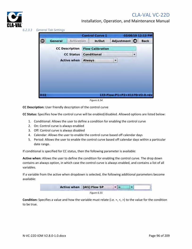
CLA-VAL VC-22D
Installation, Operation, and Maintenance Manual
N-VC-22D IOM V2.8.0-1.0.docx Page 96 of 209
6.2.3.3 General Tab Settings
Figure 6.54
CC Description: User friendly description of the control curve
CC Status: Specifies how the control curve will be enabled/disabled. Allowed options are listed below:
1. Conditional: Allows the user to define a condition for enabling the control curve
2. On: Control curve is always enabled
3. Off: Control curve is always disabled
4. Calendar: Allows the user to enable the control curve based off calendar days
5. Period: Allows the user to enable the control curve based off calendar days within a particular
date range.
If conditional is specified for CC status, then the following parameter is available:
Active when: Allows the user to define the condition for enabling the control curve. The drop down
contains an always option, in which case the control curve is always enabled, and contains a list of all
variables.
If a variable from the active when dropdown is selected, the following additional parameters become
available:
Figure 6.55
Condition: Specifies a value and how the variable must relate (i.e. =, <, >) to the value for the condition
to be true.

CLA-VAL VC-22D
Installation, Operation, and Maintenance Manual
N-VC-22D IOM V2.8.0-1.0.docx Page 97 of 209
6.2.3.4 Activation Tab Settings
Figure 6.56
The activation tab is only enabled if CC Status is set to “Calendar” or “Period” on the general tab.
Day of the week: Specify the day of the week that control curve will be enabled.
If the CC Status is set to “Calendar”, then the following setting is visible as shown in FIGURE 6.56.
Month of the year: Specify the month of the year that the control curve will be enabled. (Only
visible if CC Status is set to “Calendar”)
Note, for the control curve to be enabled the current date must satisfy both the day of week
and month of year conditions.
If the CC Status is set to “Period”, then the following setting is visible as shown in FIGURE 6.57.
Period: Specify the date range that the control curve will be enabled. (Only visible if CC Status is
set to “Period”)
Note, for the control curve to be enabled the current date must satisfy both the day of week
and period conditions.
Figure 6.57

CLA-VAL VC-22D
Installation, Operation, and Maintenance Manual
N-VC-22D IOM V2.8.0-1.0.docx Page 98 of 209
6.2.3.5 In/Out Tab Settings
Figure 6.58
Input Source: Specifies the input or variable that will be will used to select the destination value.
Input Current Value: Displays the current value of the selected input source.
Output Destination: Specifies the output or variable that will hold the destination value.
Apply default value: If the “On invalid input” checkbox is checked, the specified value will be written to
the destination if the input source value is invalid. If the “On CC disabled” checkbox is checked, the
specified value will be written to the destination if the control curve is disabled.
Current Value: Displays the current value of the destination.
Override: If pressed, allows the user to specify a value that gets written to the destination regardless of
source value.

CLA-VAL VC-22D
Installation, Operation, and Maintenance Manual
N-VC-22D IOM V2.8.0-1.0.docx Page 99 of 209
6.2.3.6 Adjustment Tab Settings
Figure 6.59
This page correlates the source value to a destination value. The left column in the table is the source
value, and the right column is the destination value. Pressing the “+” button in the upper right corner of
the table adds a new row, and the user can specify a destination value associated with a new source
value. Pressing the trash can icon of any row deletes the row. The graph to the right of the table shows
the source values on the horizontal axis and the corresponding values on the vertical axis.
Mode: There are two options available, “slope” and “step”. If “step” is selected, a linear interpolation is
performed to estimate the destination value if source value is between two rows. If “step” is selected,
no interpolation is performed. The destination value outputted is from the row that has the source value
closest too but lower than the current source value.
6.2.3.7 R/T View Tab Settings
Figure 6.60

CLA-VAL VC-22D
Installation, Operation, and Maintenance Manual
N-VC-22D IOM V2.8.0-1.0.docx Page 100 of 209
The R/T View tab shows a graph with destination values on the vertical axis and source values on the
horizontal access. The graph also indicates the current source value and corresponding destination value
that is being outputted.
6.2.4 Averagers
6.2.4.1 Description
Takes a moving average of an input/variable and outputs the result to another variable. The time frame
of the moving average is user adjustable.
6.2.4.2 Navigation Path
1. Start at the home screen
2. Long up
3. Click on “Averages”
4. Click on “Averager #”
6.2.4.3 Configure Tab Settings
Figure 6.61
Averager is enabled: If checked, an internal variable is created and the moving average of the specified
input is logged to the internal variable.
Name: Specifies the name of the internal variable that holds the moving average.
Input: Specifies the input or variable that is averaged.
Input Min – Max: Displays the minimum and maximum value of the input.
Output Variable: Displays the name of the internal variable that holds the moving average.
Output Units: Units to use when writing average to output variable.
Output Min – Max: Displays the minimum and maximum value of the output.

CLA-VAL VC-22D
Installation, Operation, and Maintenance Manual
N-VC-22D IOM V2.8.0-1.0.docx Page 101 of 209
Averaging Period: Specifies how far back in history the average will be taken over (e.g. If 1 hour is
specified, the moving average is always taken over the past 1 hour.)
Display on home page: If checked, the average value will be displayed at the bottom of the home page.
6.2.4.4 General Tab Settings
Figure 6.62
The general tab displays the current average and has a shortcut to change the averaging period that
available on the configure tab as well. See section 6.2.4.3 for more information.
6.2.5 Actions
6.2.5.1 Description
Actions allow the user to define conditions, and then specify an action the VC-22D will take if the
conditions are met. For example, actions can be used to force a solenoid open if a particular analog
input is below a certain value.
6.2.5.2 Navigation Path
1. Start at the home screen
2. Long up
3. Click on “!Actions!”

CLA-VAL VC-22D
Installation, Operation, and Maintenance Manual
N-VC-22D IOM V2.8.0-1.0.docx Page 102 of 209
6.2.5.3 Action Settings
Figure 6.63
There are four action tabs, one for each available action. Each tab has the same configuration
parameters described below.
Description: User friendly description of the action
!A! Enabled/Disabled: Clicking this button enables/disables the action. When the action is disabled, it
will not write anything to the specified output even if the conditions are met. The button says “!A!
Enabled” when the action is enabled and “!A! Disabled” when disabled.
Condition 1/2: Summarizes conditions that trigger the action on or off. When the action is triggered on,
it sends a value to a specified output/variable. When the action is triggered off, it stops sending that
value. Highlighting the condition and pressing “OK” opens the page described in the section 6.2.5.3.1.
AND/OR: The AND/OR dropdown specifies whether one or both conditions must be true to trigger the
action on. If “AND” is selected, both conditions must be true. If “Or” is selected, only one condition must
to true.
Output: Specifies what is written to an output or variable when the action is triggered on or off.
Highlighting the output and pressing “OK” opens the page described in section 6.2.5.3.2.

CLA-VAL VC-22D
Installation, Operation, and Maintenance Manual
N-VC-22D IOM V2.8.0-1.0.docx Page 103 of 209
6.2.5.3.1 Condition Screen
Figure 6.64
This page defines what range of values an input or variable must have for the action to be triggered
on/off. The leftmost dropdown specifies the input or variable. The middle dropdown menu specifies
whether that value must be greater than, equal too, or less than a comparison value. The rightmost
dropdown specifies the source of the comparison value (input, variable, or user specified value). The
hysteresis textbox specifies the distance between the “trigger on” value and “trigger off” value. Using a
hysteresis prevents the action from being triggered on/off frequently.
If the rightmost dropdown is set to “—value—“, then an additional text box appears allowing the user to
enter a specified value.
6.2.5.3.2 Output Screen
Figure 6.65

CLA-VAL VC-22D
Installation, Operation, and Maintenance Manual
N-VC-22D IOM V2.8.0-1.0.docx Page 104 of 209
Output: Specifies the output or variable that is written too.
Value On: Specifies the value that’s written to the output.
Value Off: Specifies what is written when the action is triggered off. There are three options:
1. No action: Output value is left unchanged when action is triggered off
2. Restore previous value: Output is returned to value that held before action was triggered on
3. Set value to: A new textbox appears, and output is set equal to the value in the new textbox
when the action is triggered off.
One-Shot: When one-shot is disabled, the action becomes active when the conditions are true and
becomes inactive when the conditions are false (after appropriate delays). When one-shot is enabled,
the action becomes active when the conditions are true, and then deactivates after a time delay.
When one-shot is disabled, the following settings are visible. See FIGURE 6.66 for a visual depiction of
the settings.
Activation Delay: Specifies the number of seconds the conditions must be true before the action
will activate.
Deactivation Delay: Specifies the number of seconds the conditions must be false before the
action will de-activate.
Min. Duration: Specifies the minimum number of seconds the action will be held on for after it
becomes active.
Figure 6.66
When one-shot is enabled, the following delay options are visible. See FIGURE 6.67 for a visual depiction
of the settings.
Activation Delay: Setting works the same as when One-Shot box is unchecked.

CLA-VAL VC-22D
Installation, Operation, and Maintenance Manual
N-VC-22D IOM V2.8.0-1.0.docx Page 105 of 209
Duration: Specifies the number of seconds the action will remain active after conditions are met
Figure 6.67
6.2.6 Signal Retransmission
6.2.6.1 Description
Signal retransmission reads the value in a specified input or variable and writes it to an analog output.
6.2.6.2 Navigation Path
1. Start at the home screen
2. Long up
3. Click on “Signal Retrans”
6.2.6.3 Signal Retransmission Settings
Figure 6.68
CLA-VAL VC-22D
Installation, Operation, and Maintenance Manual
N-VC-22D IOM V2.8.0-1.0.docx Page 106 of 209
There are four signal retransmission tabs, one for each available signal retransmission. Each tab has the
same configuration parameters described below.
Retransmission Enabled/Disabled: Clicking this button enables/disables the signal retransmission.
When the retransmission is disabled, it will not write anything to the specified output. The button says
“Retransmission Disabled” when the action is enabled and “Retransmission Disabled” when disabled.
Input Source: Specifies the input or variable whose value will be sent via an analog output.
Output Destination: Specifies the analog output that will be written too.

CLA-VAL VC-22D
Installation, Operation, and Maintenance Manual
N-VC-22D IOM V2.8.0-1.0.docx Page 107 of 209
6.2.7 Totalizer
6.2.7.1 Description
The totalizer continually tracks the total volume of water that’s flowed through the valve by monitoring
the current flow rate. The total volume can be outputted to a variable or analog output.
The totalizer function is only enabled in certain ValvApps and cannot be enabled by the user. The user
must choose a ValvApp from the standard library that has the totalizer enabled or contact a Cla-Val
representative to get a custom ValvApp.
6.2.7.2 Navigation Path
1. Start at the home screen
2. Long up
3. Click on “Totalizer #”
6.2.7.3 Totalizer Settings
Figure 6.69
Source: Specifies the analog input or variable that has the current flow rate through the valve
Output: Specifies the variable or analog output that the total volume is written too
Active when: Allows the totalizing function to be paused when a certain condition is met
Current Value: Displays the total volume being written to the output currently
Last reset: Date and time the totalizer was last reset
Set to: Value that the total value will be reset to when the apply button is clicked
6.2.8 eDrive34
6.2.8.1 Description
Allows a 34 series actuator to be configured through the VC-22D. The 34 series actuator must be
connected to the VC-22D over an RS485 cable. The eDrive34 function in the VC-22D offers the same

CLA-VAL VC-22D
Installation, Operation, and Maintenance Manual
N-VC-22D IOM V2.8.0-1.0.docx Page 108 of 209
capabilities of the Windows based eDrive software but does not require a laptop or special orange
connecting cable.
The eDrive34 function will only be available in the ValvApp if a 34 series actuator is probably connected
to the VC-22D at the time the VC-22D powers on. After the actuator is first connected to the VC-22D, the
VC-22D must be rebooted before the eDrive34 function is visible.
6.2.8.2 Navigation
1. Start at the home screen
2. Long up
3. Click on “eDrive32”
6.2.8.3 eDrive34 Settings
See series 34 actuator documentation for eDrive configuration instructions.
6.2.9 Input Settings
6.2.9.1 Description
The input settings show the current electrical signal being received on each analog/digital input and
allow configuration changes to be made (e.g. input names, engineering units, and scaling).
6.2.9.2 Navigation Path
1. Start at the home screen
2. Long left
6.2.9.3 Configure Input Settings
Figure 6.70
The configure inputs screen shows the number of milliamps being received by each analog input. It also
shows the engineering value associated with the milliamp signal. Scrolling to the bottom of the page
shows the on/off state of each digital input. Pressing short up or down changes which input is
highlighted.

CLA-VAL VC-22D
Installation, Operation, and Maintenance Manual
N-VC-22D IOM V2.8.0-1.0.docx Page 109 of 209
Analog Input: Highlighting an analog input as shown in FIGURE 6.71 and pressing short left opens the
“configure analog input settings” screen (see section 6.2.9.4).
Figure 6.71
Digital Input: Highlighting a digital input as shown in FIGURE 6.72 and pressing short left opens the
“configure digital input settings” screen (see section 6.2.9.5).
Figure 6.72
Add Input: Clicking the icon shown in FIGURE 6.73 allows the user to add an unused analog/digital input
channel. Newly added inputs can be used in places like actions, signal retransmission, remapping, or be
displayed on the home screen. When the add input icon is clicked, a new screen appears as shown in
FIGURE 6.74. The screen shows a list of spare analog/digital inputs, and selecting one adds the input to
the “configure input settings” screen.
Figure 6.73
Figure 6.74
Remap Input: Clicking the icon shown in FIGURE 6.75 allows the user to copy the value of one
analog/digital input to another. See section 6.2.9.6.
Figure 6.75

CLA-VAL VC-22D
Installation, Operation, and Maintenance Manual
N-VC-22D IOM V2.8.0-1.0.docx Page 110 of 209
6.2.9.4 Configure Analog Input
Figure 6.76
Display Name: User friendly name of the analog input
Units: Specifies the engineering units associated with the scaled value
Decimal: Number of decimal places to display on the screen when showing the value of the analog input
Signal Type: Always fixed at 4-20mA. Indicates the following input is for an analog signal.
4 mA = min: Specifies the scaled value that is represented by a 4 mA signal
20 mA = max: Specifies the scaled value that is represented by a 20 mA signal
Signal Filter: Specifies how much noise will be filtered out of the analog signal. The higher the number,
the more noise removed. An analog signal with a high filter will change slower as well.
Lost Signal (< 3.6 mA): Specifies what will occur if the analog signal drops below 3.6 mA (which normally
occurs if the signal wires are disconnected. The allowed options are:
1. Do nothing: Continue calculating the scaled value based on the milliamp signal. (e.g. If the signal
is 3.2 mA, interpolate the scaled value based on the 4 mA min and 20 mA max scaled values.)
2. Keep value: Keep the value that existed in the analog input just before the signal was lost
3. Default value: Revert to a default value. A new textbox appears to the right which allows the
user to specify the default value.
Use as RSP/LSP: By checking this box, the analog input becomes a setpoint and the user can then toggle
the input between remote setpoint (RSP) and local setpoint (LSP) mode. See section 8.1.2 for a
description of RSP/LSP mode.
Display on home page: By checking this box, the value of the analog input will be displayed at the
bottom of the home screen.

CLA-VAL VC-22D
Installation, Operation, and Maintenance Manual
N-VC-22D IOM V2.8.0-1.0.docx Page 111 of 209
Checkbox Icon: Clicking the icon shown in FIGURE 6.77 saves changes and navigates back to the
configure inputs screen.
Figure 6.77
Trashcan Icon: Clicking the icon shown in FIGURE 6.78 cancels any changes and navigates back to the
configure inputs screen.
Figure 6.78
Configure Remote Recopy: The icon shown in FIGURE 6.79 is not applicable to North America, as it
requires a cellular connection. This is a European feature only.
Figure 6.79
Configure min/max milliamps: Clicking the icon shown in FIGURE 6.80 opens the page shown in FIGURE
6.81.
Figure 6.80
Figure 6.81

CLA-VAL VC-22D
Installation, Operation, and Maintenance Manual
N-VC-22D IOM V2.8.0-1.0.docx Page 112 of 209
The custom scaling screen shown in FIGURE 6.81 allows the minimum and maximum milliamp range to
be changed. This is useful for cases when the analog input ranges from 0-25mA instead of 4-20mA.
Parameters on the screen are described below:
Max Milliamps: Specifies the maximum allowed milliamps on the analog input.
Acquire HI: Clicking this button reads the current milliamps received on the analog input and writes that
value to the Max Milliamps text box.
Minimum Milliamps: Specifies the minimum allowed milliamps on the analog input.
Acquire LO: Clicking this button reads the current milliamps received on the analog input and writes that
value to the Min Milliamps text box.
If custom scaling changes are made, the “4 mA = min” field on the configure inputs screen is updated
with the new minimum milliamps and the “20 mA = max” field is updated with the new maximum
milliamps.
6.2.9.5 Configure Digital Input
Figure 6.82
Display Name: User friendly description of the digital input.
Use as RSP/LSP: By checking this box, the digital input becomes a setpoint and the user can then toggle
the input between remote setpoint (RSP) and local setpoint (LSP) mode. See section 8.1.2 for a
description of RSP/LSP mode.
Display on home page: By checking this box, the value of the analog input will be displayed at the
bottom of the home screen.

CLA-VAL VC-22D
Installation, Operation, and Maintenance Manual
N-VC-22D IOM V2.8.0-1.0.docx Page 113 of 209
6.2.9.6 Remap Input
Figure 6.83
Remap input is used when an input is wired to a channel on the VC-22D that is different than what the
ValvApp is expecting (e.g. the position feedback is wired to AI2 but the ValvApp is reading AI5 for
position feedback). If it’s too difficult to change the wiring, the remap input feature will allow the user to
continually copy the value from AI2 to AI5. There are four tabs on this screen, one for each available
remap. Each tab has the same parameters, and a description of each parameter is below:
Recopy Disabled: Clicking this button enables/disables the input remap. When the remap is disabled, it
will no longer copy the value of the source input to the destination input. The button says “Recopy
Enabled” when it’s enabled, and “Recopy Disabled” when it’s disabled.
Source: Specifies the source of the value being copied. All inputs are listed in the source dropdown.
Destination: Specifies the destination that the source value is being copied too. Only inputs with the
same engineering units and scaling as the source are available in the destination dropdown.
6.2.10 Output Settings
6.2.10.1 Description
The output settings show the current electrical signal being sent on each analog/digital output and allow
configuration changes to be made (e.g. output names, engineering units, and scaling).
6.2.10.2 Navigation Path
1. Start at the home screen
2. Long right

CLA-VAL VC-22D
Installation, Operation, and Maintenance Manual
N-VC-22D IOM V2.8.0-1.0.docx Page 114 of 209
6.2.10.3 Configure Output Settings
Figure 6.84
The configure outputs screen shows the number of milliamps being sent by each analog output. It also
shows the engineering value associated with the milliamp signal. Scrolling to the bottom of the page
shows the on/off state of each digital output. Pressing short up or down changes which input is
highlighted.
Analog Output: Highlighting an analog output as shown in FIGURE 6.85 and pressing short right opens
the “configure analog input settings” screen (see section 6.2.10.4).
Figure 6.85
Digital Output: Highlighting a digital output as shown in FIGURE 6.86 and pressing short right opens the
“configure digital output settings” screen (see section 6.2.10.5).
Figure 6.86

CLA-VAL VC-22D
Installation, Operation, and Maintenance Manual
N-VC-22D IOM V2.8.0-1.0.docx Page 115 of 209
6.2.10.4 Configure Analog Output
Figure 6.87
Display Name: User friendly name of the analog output
Units: Specifies the engineering units associated with the scaled value
Decimal: Number of decimal places to display on the screen when showing the value of the analog
output
Signal Type: Always fixed at 4-20mA. Indicates the following output is for an analog output.
4 mA = min: Specifies the scaled value that is represented by a 4 mA signal
20 mA = max: Specifies the scaled value that is represented by a 20 mA signal
Default value: Specifies the value used for the analog output before the VC-22D writes a value to it.
Ramping: Ramping causes the analog output to gradually change from a previous value to a current
value. The ramping number specifies the amount the output will change per minute. A larger number
causes the output to change slower. Specifying “Off” or 0 removes all ramping, and the analog output
changes from previous value to current value immediately.
Display on home page: By checking this box, the value of the analog output will be displayed at the
bottom of the home screen.

CLA-VAL VC-22D
Installation, Operation, and Maintenance Manual
N-VC-22D IOM V2.8.0-1.0.docx Page 116 of 209
6.2.10.5 Configure Digital Output
Figure 6.88
Display Name: User friendly description of digital output
Type: Specifies if digital output is on/off or PWM. See section 6.2.2.5 for description of PWM.
Cycle Time: This setting is only available when Type is set to PWM. This specifies the PWM cycle time.
See section 6.2.2.5 for more details.
Default Value: Value outputted before VC-22D writes a value to digital output.
Display on home page: By checking this box, the value of the analog output will be displayed at the
bottom of the home screen.
Power optimization: When unchecked, the VC-22D will send a continuous high voltage signal whenever
the output is active. When checked, the VC-22D will send a continuous high voltage followed by a series
of high frequency pulses. This feature is intended to be used when the digital output is connected to a
solenoid. The continuous signal actuates the solenoid and then the high frequency pulses maintain the
position. This allows less power to be sent to the solenoid which reduces solenoid temperature. By
default, the setting is disabled. This feature has only been validated on solenoids attached to Cla-Val’s
sold in the European market. It is recommended to keep this feature disabled unless told to enable it by
a Cla-Val representative.

CLA-VAL VC-22D
Installation, Operation, and Maintenance Manual
N-VC-22D IOM V2.8.0-1.0.docx Page 117 of 209
7 Web Interface The VC-22D has a web interface which allows for basic administrative tasks like uploading new ValvApps
or downloading log files via a web browser. The web interface can be enabled/disabled using the VC-
22D display per section 6.1.17.3. The following sub sections detail how to access the web interface and
navigate within it.
All information available on the web interface is also available directly via the VC-22D’s display. The web
interface simply provides an alternative means of accessing/configuring some of the VC-22D settings.
7.1 Access the Web Interface Connect a computer to the VC-22D via an Ethernet cable. Ensure the computer is on the same IP subnet
as the VC-22D (see section 6.1.11.3). Open the computer’s internet browser and go to the VC-22D’s URL
(see section 6.1.17.3).
7.2 Navigating the Web Interface The VC-22D’s web interface consists of a navigation bar on the left hand side that lists each page of the
interface. The home page is the “Information” page which is shown in FIGURE 7.1 and described in a
following section.
Figure 7.1
7.2.1 Information Page The “Information” page is shown in FIGURE 7.1. It provides general status information about the VC-22D.
All information displayed on this page can also be found on the “Information” screen of the VC-22D (see
section 6.1.1).

CLA-VAL VC-22D
Installation, Operation, and Maintenance Manual
N-VC-22D IOM V2.8.0-1.0.docx Page 118 of 209
7.2.2 Logging Page
Figure 7.2
The logging page displays the same settings available on the “Configure Logs” screen (see section 6.1.8)
and “Export Logs” screen (see section 6.1.9) of the VC-22D display. Logging can be disabled, the
frequency of logging can be adjusted, and the log files for a particular time frame can be downloaded
from the controller to your computer.
7.2.3 App Management Page
Figure 7.3
The app management page provides the same capabilities available on the backup, restore, export, and
import application screens of the VC-22D (see sections 6.1.2 - 6.1.5). The page allows a backup of the
current ValvApp to be saved to the VC-22D’s permanent storage. It also allows a ValvApp that’s been

CLA-VAL VC-22D
Installation, Operation, and Maintenance Manual
N-VC-22D IOM V2.8.0-1.0.docx Page 119 of 209
previously backed up in the VC-22D’s storage to be restored. Additionally, the current ValvApp can be
exported to the computer or imported from the computer.
7.2.4 Advanced Page
Figure 7.4
The advanced page provides the same capabilities as available on the reboot, engine update, and
diagnostics to USB screens of the VC-22D (see sections 6.1.19 - 6.1.21). This page allows for the VC-22D
engine to be updated via a file stored on the computer, diagnostics files to be uploaded to the
computer, and the VC-22D to be rebooted.

CLA-VAL VC-22D
Installation, Operation, and Maintenance Manual
N-VC-22D IOM V2.8.0-1.0.docx Page 120 of 209
8 Valve Operation The valve can be fully controlled using just the VC-22D’s navigation buttons and display. The following
sections described how to do valve control operations like setpoint changes and input/output overrides.
8.1 Setpoint Changes A setpoint is considered to be any value that the user specifies and the VC-22D uses as a target for valve
control. Examples of setpoints include flow rate setpoints, tank level setpoints, valve position setpoints,
and downstream/upstream pressure setpoints. Setpoints are what operators specify to ensure the valve
operates as required.
Setpoints are stored in the VC-22D as interactive variables, analog inputs, or digital inputs.
8.1.1 Interactive Variable Interactive variables can be changed locally using the VC-22D display and navigation buttons. To change
an interactive variable, do the following:
1. Starting from the home screen, press short down and wait for the interactive variable screen to
be displayed as shown in FIGURE 8.1.
Figure 8.1

CLA-VAL VC-22D
Installation, Operation, and Maintenance Manual
N-VC-22D IOM V2.8.0-1.0.docx Page 121 of 209
2. Highlight the interactive variable to be changed and press “OK”. Enter the desired value as
shown in FIGURE 8.2.
Figure 8.2
8.1.2 Remote/Local Setpoint If a setpoint is being transmitted remotely as an analog or digital input, it’s useful to be able to override
the remote setpoint with a local setpoint. To enable a local override of a remote setpoint, follow the
instructions in section 6.2.7 and check “Use as RSP/LSP”. Once this box is checked, the input then gets
listed in the interactive variable list and can be changed like an interactive variable. To change a setpoint
with RSP/LSP enabled, do the following:
1. Starting from the home screen, press short down and wait for the interactive variable screen to
be displayed as shown in FIGURE 8.3.
Figure 8.3

CLA-VAL VC-22D
Installation, Operation, and Maintenance Manual
N-VC-22D IOM V2.8.0-1.0.docx Page 122 of 209
2. Use the up and down navigation buttons to highlight the input to be changed as shown in
FIGURE 8.4.
Figure 8.4
3. Use the left and right navigation buttons to highlight the “RSP/LSP” graphic as shown in FIGURE
8.5.
Figure 8.5
4. Press “OK” so the “LSP” is highlighted in green as shown in FIGURE 8.6.

CLA-VAL VC-22D
Installation, Operation, and Maintenance Manual
N-VC-22D IOM V2.8.0-1.0.docx Page 123 of 209
Figure 8.6
5. Use the left and right navigation buttons to highlight the numerical value and press “OK”. Enter
the desired numerical value as shown in FIGURE 8.7.
Figure 8.7
To remove the local override, follow the procedure above but change the “RSP/LSP” graphic to “RSP”.
The value will then revert back to the remote setpoint.
8.2 Local Input Override At times, it’s useful to override an input or output signal going to or from the VC-22D. Overriding inputs
is generally needed when a sensor is either malfunctioning or not wired yet, but the valve still needs to
be controlled. The user can override an input with an approximate value that should be coming from the
sensor.

CLA-VAL VC-22D
Installation, Operation, and Maintenance Manual
N-VC-22D IOM V2.8.0-1.0.docx Page 124 of 209
To override an input, do the following:
1. From the home screen, press short left and wait for the input values screen to appear as shown
in FIGURE 8.8.
Figure 8.8
2. Use the up and down navigation buttons to highlight the input to be overridden as shown in
FIGURE 8.9.
Figure 8.9

CLA-VAL VC-22D
Installation, Operation, and Maintenance Manual
N-VC-22D IOM V2.8.0-1.0.docx Page 125 of 209
3. Press short left and wait for the override screen to appear as shown in FIGURE 8.10.
Figure 8.10
4. Press “OK” and input the desired value as shown in FIGURE 8.11.
Figure 8.11
5. Press “OK” and wait for the screen shown in FIGURE 8.12 to be displayed. Confirm the change by
pressing “OK” or press the right navigation button to cancel.

CLA-VAL VC-22D
Installation, Operation, and Maintenance Manual
N-VC-22D IOM V2.8.0-1.0.docx Page 126 of 209
Figure 8.12
8.3 Local Output Override Overriding outputs is typically necessary when testing solenoids on the valve. Outputs are overridden
using a similar procedure for inputs. To get to the output values screen, press short right. Then highlight
the output to override and press short right again. Reference the input override procedure in section 8.2
for additional instructions.
9 Modbus Interface The VC-22D has a Modbus server. It supports Modbus TCP/IP and Modbus RTU. The device’s Ethernet
port can be used for Modbus TCP/IP communications, and the RS232 and RS485 ports are available for
Modbus RTU communications. Both Modbus TCP/IP and RTU can be used simultaneously.
The Modbus registers hold the VC-22D’s inputs, outputs, and variable values. It also stores status bits for
each IO point that indicate if a 4-20mA sign is out of range, a local override is enabled, an alarm is active,
etc. Modbus clients can read these registers to monitor the VC-22D. A client can also place individual
inputs and outputs in an override mode, and then overwrite the VC-22D’s input/output value. Override
mode is beneficial for clients that need to send a setpoint or sensor value to the VC-22D.
The VC-22D Modbus server can operate using one of two mapping schemes, “Standard” or “Cla-Val”.
“Standard” is the newest scheme and was introduced with engine 2.5.0. It organizes the registers in a
way that is consistent with most other industrial control devices. “Cla-Val” is a legacy scheme that was
used prior to engine 2.5.0 and has been left as an option in new engines for backwards compatibility.
The “standard” scheme is recommended and is enabled by default in new VC-22Ds. VC-22Ds that are
upgraded from a previous engine will maintain whatever mode the server was in before the upgrade.
9.1 Standard Mode Per the Modbus specification, the Modbus registers are broken into four primary tables:
1. 0x registers (Coil Table)

CLA-VAL VC-22D
Installation, Operation, and Maintenance Manual
N-VC-22D IOM V2.8.0-1.0.docx Page 127 of 209
2. 1x registers (Discrete Input Table)
3. 3x registers (Analog Input Table)
4. 4x registers (Holding Table)
9.1.1 0x Registers (Coil Table) The coils table provides the energized status of each digital output on the VC-22D. The following table
describes the supported Modbus function codes and registers for the coils table:
Supported Function Codes
• 01 Read Coils
Starting Register Function Data Type Access
00000 SO1 Value Bit Read Only
00001 SO2 Value Bit Read Only
00002 RO1 Value Bit Read Only
00003 RO2 Value Bit Read Only
Digital outputs may be configured in digital mode or PWM mode, and that effects the value stored in the
corresponding register. See section 6.2.10.5 for a description of digital mode and PWM mode. When the
output is in digital mode, a register value of 1 means the output is energized, and a register value of 0
means the output is de-energized. When the output is in PWM mode, a register value of 1 means the
output is sending a PWM signal greater than 0, and a register value of 0 means the output is de-
energized.
9.1.2 1x Registers (Discrete Input Table) The discrete inputs table indicates the signal being received by each digital input. The following table
describes the supported Modbus function codes and registers for the discrete inputs table:
Supported Function Codes
• 02 Read Discrete Inputs
Starting Register Function Data Type Access
10000 DI1 Value Bit Read Only
10001 DI2 Value Bit Read Only
10002 DI3 Value Bit Read Only
10003 DI4 Value Bit Read Only
10004 DI5 Value Bit Read Only
10005 DI6 Value Bit Read Only
A register value of 1 means the digital input is detecting a closed circuit. A register value of 0 means the
digital input is detecting an open circuit.
9.1.3 3x Registers (Analog Input Table) The input table indicates the analog signal being received by each digital input. The following table
describes the supported Modbus function codes and registers for the analog inputs table:

CLA-VAL VC-22D
Installation, Operation, and Maintenance Manual
N-VC-22D IOM V2.8.0-1.0.docx Page 128 of 209
Supported Function Codes
• 04 Read Input Register
Starting Register Function Data Type Access
30000 AI1 Value Float Read Only
30002 AI2 Value Float Read Only
30004 AI3 Value Float Read Only
30006 AI4 Value Float Read Only
30008 AI5 Value Float Read Only
30010 AI6 Value Float Read Only
30012 DI1_C Value Float Read Only
30014 DI2_C Value Float Read Only
30016 DI3_C Value Float Read Only
30018 DI4_C Value Float Read Only
30020 DI5_C Value Float Read Only
30022 DI6_C Value Float Read Only
30024 DI1_F Value Float Read Only
30026 DI2_F Value Float Read Only
30028 DI3_F Value Float Read Only
30030 DI4_F Value Float Read Only
30032 DI5_F Value Float Read Only
30034 DI6_F Value Float Read Only
The value stored in the registers is identical to the engineering value displayed on the VC-22D display.
The value will be scaled, filtered, and any overrides will be applied. If a loss of signal exists, the loss of
signal value will be stored in the registers.
9.1.4 4x Registers (Holding Table) The holding table contains registers that provide status information about inputs and outputs, allow
Modbus override values to be written to inputs and outputs, and allow ValvApp specific variables to be
modified. The following table describes the supported Modbus function codes and registers for the
holding table:
Supported Function Calls
• 03 Read Holding Registers
• 06 Write Single Registers
• 16 Write Multiple Registers
Starting Register Info
40000 Function Analog input out of range (OOR) status
Data Type Word
Access Read Only

CLA-VAL VC-22D
Installation, Operation, and Maintenance Manual
N-VC-22D IOM V2.8.0-1.0.docx Page 129 of 209
Description Each bit represents out of range status of an analog input. 1 means OOR active, 0 means OOR inactive. Bit 0 = AI1 OOR Status Bit 1 = AI2 OOR Status … Bit 5 = AI6 OOR Status Bits 6-15 are unused and always 0
40001 Function Digital counter input out of range (OOR) status
Data Type Word
Access Read Only
Description Each bit represents out of range status of a digital counter input. 1 means OOR active, 0 means OOR inactive. Bit 0 = DI1_C OOR Status Bit 1 = DI2_C OOR Status … Bit 5 = DI6_C OOR Status Bits 6-15 are unused and always 0
40002 Function Digital frequency input out of range (OOR) status
Data Type Word
Access Read Only
Description Each bit represents out of range status of a digital frequency input. 1 means OOR active, 0 means OOR inactive. Bit 0 = DI1_F OOR Status Bit 1 = DI2_F OOR Status … Bit 5 = DI6_F OOR Status Bits 6-15 are unused and always 0
40003 Function Analog input local override (LOVR) status
Data Type Word
Access Read Only
Description Each bit represents LOVR status of an analog input. 1 means LOVR active, 0 means LOVR inactive. Bit 0 = AI1 OOR Status Bit 1 = AI2 OOR Status … Bit 5 = AI6 OOR Status Bits 6-15 are unused and always 0
40004 Function Digital input local override (LOVR) status
Data Type Word
Access Read Only

CLA-VAL VC-22D
Installation, Operation, and Maintenance Manual
N-VC-22D IOM V2.8.0-1.0.docx Page 130 of 209
Description Each bit represents LOVR status of a digital input. 1 means LOVR active, 0 means LOVR inactive. Bit 0 = DI1 OOR Status Bit 1 = DI2 OOR Status … Bit 5 = DI6 OOR Status Bits 6-15 are unused and always 0
40005 Function Digital counter input local override (LOVR) status
Data Type Word
Access Read Only
Description Each bit represents LOVR status of a digital counter input. 1 means LOVR active, 0 means LOVR inactive. Bit 0 = DI1_C OOR Status Bit 1 = DI2_C OOR Status … Bit 5 = DI6_C OOR Status Bits 6-15 are unused and always 0
40006 Function Digital frequency input local override (LOVR) status
Data Type Word
Access Read Only
Description Each bit represents LOVR status of a digital frequency input. 1 means LOVR active, 0 means LOVR inactive. Bit 0 = DI1_F OOR Status Bit 1 = DI2_F OOR Status … Bit 5 = DI6_F OOR Status Bits 6-15 are unused and always 0
40007 Function Analog input Modbus override command
Data Type Word
Access Read-Write
Description Each bit represents Modbus override command of an analog input. 1 means override active, 0 means override inactive. Bit 0 = AI1 Override Status Bit 1 = AI2 Override Status … Bit 5 = AI6 Override Status Bits 6-15 are unused and always 0
40008 Function Digital input Modbus override command
Data Type Word
Access Read-Write

CLA-VAL VC-22D
Installation, Operation, and Maintenance Manual
N-VC-22D IOM V2.8.0-1.0.docx Page 131 of 209
Description Each bit represents Modbus override command of a digital input. 1 means override active, 0 means override inactive. Bit 0 = DI1 Override Status Bit 1 = DI2 Override Status … Bit 5 = DI6 Override Status Bits 6-15 are unused and always 0
40009 Function Digital counter input Modbus override command
Data Type Word
Access Read-Write
Description Each bit represents Modbus override command of a digital counter input. 1 means override active, 0 means override inactive. Bit 0 = DI1_C Override Status Bit 1 = DI2_C Override Status … Bit 5 = DI6_C Override Status Bits 6-15 are unused and always 0
40010 Function Digital frequency input Modbus override command
Data Type Word
Access Read-Write
Description Each bit represents Modbus override command of a digital frequency input. 1 means override active, 0 means override inactive. Bit 0 = DI1_F Override Status Bit 1 = DI2_F Override Status … Bit 5 = DI6_F Override Status Bits 6-15 are unused and always 0
40011 Function Analog output local override (LOVR) status
Data Type Word
Access Read Only
Description Each bit represents LOVR status of an analog output. 1 means LOVR active, 0 means LOVR inactive. Bit 0 = AO1 OOR Status Bit 1 = AO2 OOR Status Bit 2 = AO3 OOR Status Bit 3 = AO4 OOR Status Bits 4-15 are unused and always 0
40012 Function Digital output local override (LOVR) status
Data Type Word
Access Read Only

CLA-VAL VC-22D
Installation, Operation, and Maintenance Manual
N-VC-22D IOM V2.8.0-1.0.docx Page 132 of 209
Description Each bit represents LOVR status of a digital output. 1 means LOVR active, 0 means LOVR inactive. Bit 0 = SO1 OOR Status Bit 1 = SO2 OOR Status Bit 2 = RO1 OOR Status Bit 3 = RO2 OOR Status Bits 4-15 are unused and always 0
40013 Function Analog output alarm status
Data Type Word
Access Read Only
Description Each bit represents alarm status of an analog output. 1 means alarm active, 0 means alarm inactive. Bit 0 = AO1 Alarm Status Bit 1 = AO2 Alarm Status Bit 2 = AO3 Alarm Status Bit 3 = AO4 Alarm Status Bits 4-15 are unused and always 0
40014 Function Digital output alarm status
Data Type Word
Access Read Only
Description Each bit represents alarm status of a digital output. 1 means alarm active, 0 means alarm inactive. Bit 0 = SO1 Alarm Status Bit 1 = SO2 Alarm Status Bit 2 = RO1 Alarm Status Bit 3 = RO2 Alarm Status Bits 4-15 are unused and always 0
40015 Function Analog output recopy status
Data Type Word
Access Read Only
Description Each bit represents recopy status of an analog output. 1 means recopy active, 0 means recopy inactive. Bit 0 = AO1 Recopy Status Bit 1 = AO2 Recopy Status Bit 2 = AO3 Recopy Status Bit 3 = AO4 Recopy Status Bits 4-15 are unused and always 0
40016 Function Digital output recopy status
Data Type Word
Access Read Only
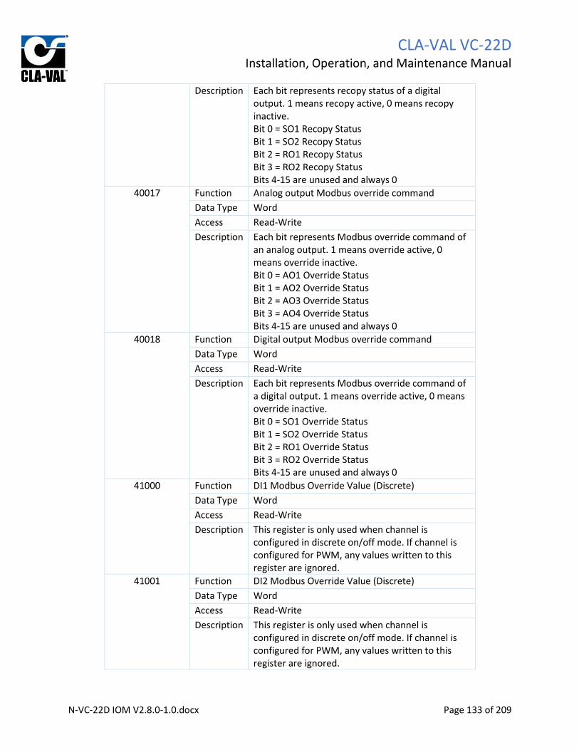
CLA-VAL VC-22D
Installation, Operation, and Maintenance Manual
N-VC-22D IOM V2.8.0-1.0.docx Page 133 of 209
Description Each bit represents recopy status of a digital output. 1 means recopy active, 0 means recopy inactive. Bit 0 = SO1 Recopy Status Bit 1 = SO2 Recopy Status Bit 2 = RO1 Recopy Status Bit 3 = RO2 Recopy Status Bits 4-15 are unused and always 0
40017 Function Analog output Modbus override command
Data Type Word
Access Read-Write
Description Each bit represents Modbus override command of an analog output. 1 means override active, 0 means override inactive. Bit 0 = AO1 Override Status Bit 1 = AO2 Override Status Bit 2 = AO3 Override Status Bit 3 = AO4 Override Status Bits 4-15 are unused and always 0
40018 Function Digital output Modbus override command
Data Type Word
Access Read-Write
Description Each bit represents Modbus override command of a digital output. 1 means override active, 0 means override inactive. Bit 0 = SO1 Override Status Bit 1 = SO2 Override Status Bit 2 = RO1 Override Status Bit 3 = RO2 Override Status Bits 4-15 are unused and always 0
41000 Function DI1 Modbus Override Value (Discrete)
Data Type Word
Access Read-Write
Description This register is only used when channel is configured in discrete on/off mode. If channel is configured for PWM, any values written to this register are ignored.
41001 Function DI2 Modbus Override Value (Discrete)
Data Type Word
Access Read-Write
Description This register is only used when channel is configured in discrete on/off mode. If channel is configured for PWM, any values written to this register are ignored.

CLA-VAL VC-22D
Installation, Operation, and Maintenance Manual
N-VC-22D IOM V2.8.0-1.0.docx Page 134 of 209
41002 Function DI3 Modbus Override Value (Discrete)
Data Type Word
Access Read-Write
Description This register is only used when channel is configured in discrete on/off mode. If channel is configured for PWM, any values written to this register are ignored.
41003 Function DI4 Modbus Override Value (Discrete)
Data Type Word
Access Read-Write
Description This register is only used when channel is configured in discrete on/off mode. If channel is configured for PWM, any values written to this register are ignored.
41004 Function DI5 Modbus Override Value (Discrete)
Data Type Word
Access Read-Write
Description This register is only used when channel is configured in discrete on/off mode. If channel is configured for PWM, any values written to this register are ignored.
41005 Function DI6 Modbus Override Value (Discrete)
Data Type Word
Access Read-Write
Description This register is only used when channel is configured in discrete on/off mode. If channel is configured for PWM, any values written to this register are ignored.
41006 Function SO1 Modbus Override Value (Discrete)
Data Type Word
Access Read-Write
Description This register is only used when channel is configured in discrete on/off mode. If channel is configured for PWM, any values written to this register are ignored.
41007 Function SO2 Modbus Override Value (Discrete)
Data Type Word
Access Read-Write
Description This register is only used when channel is configured in discrete on/off mode. If channel is configured for PWM, any values written to this register are ignored.
41008 Function RO1 Modbus Override Value (Discrete)

CLA-VAL VC-22D
Installation, Operation, and Maintenance Manual
N-VC-22D IOM V2.8.0-1.0.docx Page 135 of 209
Data Type Word
Access Read-Write
Description This register is only used when channel is configured in discrete on/off mode. If channel is configured for PWM, any values written to this register are ignored.
41009 Function RO2 Modbus Override Value (Discrete)
Data Type Word
Access Read-Write
Description This register is only used when channel is configured in discrete on/off mode. If channel is configured for PWM, any values written to this register are ignored.
42000 Function AI1 Modbus Override Value
Data Type Float
Access Read-Write
Description If corresponding Modbus override bit is set to 1, VC-22D will use this register value instead of hardwired signal. If corresponding Modbus override is set to 0, writes to the register will be ignored. Reads will provide the scaled hardwired signal value.
42002 Function AI2 Modbus Override Value
Data Type Float
Access Read-Write
Description If corresponding Modbus override bit is set to 1, VC-22D will use this register value instead of hardwired signal. If corresponding Modbus override is set to 0, writes to the register will be ignored. Reads will provide the scaled hardwired signal value.
42004 Function AI3 Modbus Override Value
Data Type Float
Access Read-Write
Description If corresponding Modbus override bit is set to 1, VC-22D will use this register value instead of hardwired signal. If corresponding Modbus override is set to 0, writes to the register will be ignored. Reads will provide the scaled hardwired signal value.
42006 Function AI4 Modbus Override Value
Data Type Float
Access Read-Write

CLA-VAL VC-22D
Installation, Operation, and Maintenance Manual
N-VC-22D IOM V2.8.0-1.0.docx Page 136 of 209
Description If corresponding Modbus override bit is set to 1, VC-22D will use this register value instead of hardwired signal. If corresponding Modbus override is set to 0, writes to the register will be ignored. Reads will provide the scaled hardwired signal value.
42008 Function AI5 Modbus Override Value
Data Type Float
Access Read-Write
Description If corresponding Modbus override bit is set to 1, VC-22D will use this register value instead of hardwired signal. If corresponding Modbus override is set to 0, writes to the register will be ignored. Reads will provide the scaled hardwired signal value.
42010 Function AI6 Modbus Override Value
Data Type Float
Access Read-Write
Description If corresponding Modbus override bit is set to 1, VC-22D will use this register value instead of hardwired signal. If corresponding Modbus override is set to 0, writes to the register will be ignored. Reads will provide the scaled hardwired signal value.
42012 Function DI1_C Modbus Override Value
Data Type Float
Access Read-Write
Description If corresponding Modbus override bit is set to 1, VC-22D will use this register value instead of hardwired signal. If corresponding Modbus override is set to 0, writes to the register will be ignored. Reads will provide the scaled hardwired signal value.
42014 Function DI2_C Modbus Override Value
Data Type Float
Access Read-Write
Description If corresponding Modbus override bit is set to 1, VC-22D will use this register value instead of hardwired signal. If corresponding Modbus override is set to 0, writes to the register will be ignored. Reads will provide the scaled hardwired signal value.
42016 Function DI3_C Modbus Override Value
Data Type Float

CLA-VAL VC-22D
Installation, Operation, and Maintenance Manual
N-VC-22D IOM V2.8.0-1.0.docx Page 137 of 209
Access Read-Write
Description If corresponding Modbus override bit is set to 1, VC-22D will use this register value instead of hardwired signal. If corresponding Modbus override is set to 0, writes to the register will be ignored. Reads will provide the scaled hardwired signal value.
42018 Function DI4_C Modbus Override Value
Data Type Float
Access Read-Write
Description If corresponding Modbus override bit is set to 1, VC-22D will use this register value instead of hardwired signal. If corresponding Modbus override is set to 0, writes to the register will be ignored. Reads will provide the scaled hardwired signal value.
42020 Function DI5_C Modbus Override Value
Data Type Float
Access Read-Write
Description If corresponding Modbus override bit is set to 1, VC-22D will use this register value instead of hardwired signal. If corresponding Modbus override is set to 0, writes to the register will be ignored. Reads will provide the scaled hardwired signal value.
42022 Function DI6_C Modbus Override Value
Data Type Float
Access Read-Write
Description If corresponding Modbus override bit is set to 1, VC-22D will use this register value instead of hardwired signal. If corresponding Modbus override is set to 0, writes to the register will be ignored. Reads will provide the scaled hardwired signal value.
42024 Function DI1_F Modbus Override Value
Data Type Float
Access Read-Write
Description If corresponding Modbus override bit is set to 1, VC-22D will use this register value instead of hardwired signal. If corresponding Modbus override is set to 0, writes to the register will be ignored. Reads will provide the scaled hardwired signal value.
42026 Function DI2_F Modbus Override Value
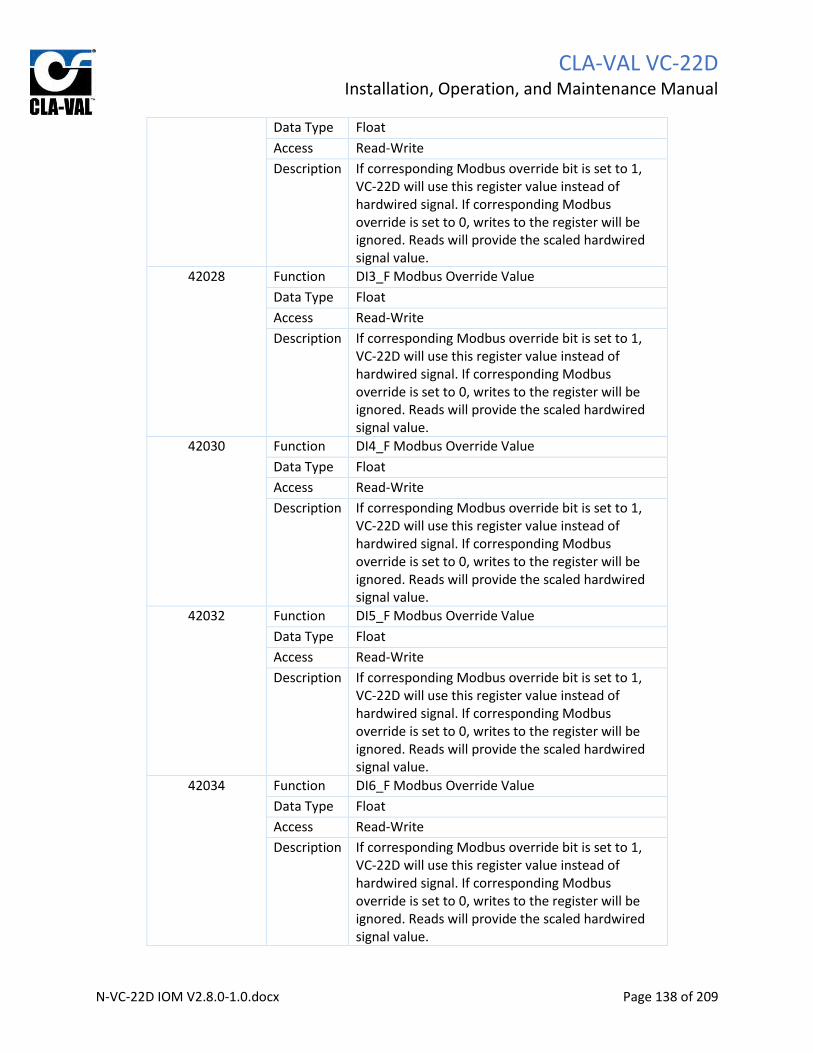
CLA-VAL VC-22D
Installation, Operation, and Maintenance Manual
N-VC-22D IOM V2.8.0-1.0.docx Page 138 of 209
Data Type Float
Access Read-Write
Description If corresponding Modbus override bit is set to 1, VC-22D will use this register value instead of hardwired signal. If corresponding Modbus override is set to 0, writes to the register will be ignored. Reads will provide the scaled hardwired signal value.
42028 Function DI3_F Modbus Override Value
Data Type Float
Access Read-Write
Description If corresponding Modbus override bit is set to 1, VC-22D will use this register value instead of hardwired signal. If corresponding Modbus override is set to 0, writes to the register will be ignored. Reads will provide the scaled hardwired signal value.
42030 Function DI4_F Modbus Override Value
Data Type Float
Access Read-Write
Description If corresponding Modbus override bit is set to 1, VC-22D will use this register value instead of hardwired signal. If corresponding Modbus override is set to 0, writes to the register will be ignored. Reads will provide the scaled hardwired signal value.
42032 Function DI5_F Modbus Override Value
Data Type Float
Access Read-Write
Description If corresponding Modbus override bit is set to 1, VC-22D will use this register value instead of hardwired signal. If corresponding Modbus override is set to 0, writes to the register will be ignored. Reads will provide the scaled hardwired signal value.
42034 Function DI6_F Modbus Override Value
Data Type Float
Access Read-Write
Description If corresponding Modbus override bit is set to 1, VC-22D will use this register value instead of hardwired signal. If corresponding Modbus override is set to 0, writes to the register will be ignored. Reads will provide the scaled hardwired signal value.

CLA-VAL VC-22D
Installation, Operation, and Maintenance Manual
N-VC-22D IOM V2.8.0-1.0.docx Page 139 of 209
42036 Function AO1 Modbus Override Value
Data Type Float
Access Read-Write
Description If corresponding Modbus override bit is set to 1, VC-22D will use this register value instead of hardwired signal. If corresponding Modbus override is set to 0, writes to the register will be ignored. Reads will provide the scaled hardwired signal value.
42038 Function AO2 Modbus Override Value
Data Type Float
Access Read-Write
Description If corresponding Modbus override bit is set to 1, VC-22D will use this register value instead of hardwired signal. If corresponding Modbus override is set to 0, writes to the register will be ignored. Reads will provide the scaled hardwired signal value.
42040 Function AO3 Modbus Override Value
Data Type Float
Access Read-Write
Description If corresponding Modbus override bit is set to 1, VC-22D will use this register value instead of hardwired signal. If corresponding Modbus override is set to 0, writes to the register will be ignored. Reads will provide the scaled hardwired signal value.
42042 Function AO4 Modbus Override Value
Data Type Float
Access Read-Write
Description If corresponding Modbus override bit is set to 1, VC-22D will use this register value instead of hardwired signal. If corresponding Modbus override is set to 0, writes to the register will be ignored. Reads will provide the scaled hardwired signal value.
42044 Function SO1 Modbus Override Value (PWM)
Data Type Float
Access Read-Write
Description If corresponding Modbus override bit is set to 1, VC-22D will use this register value instead of hardwired signal. If corresponding Modbus override is set to 0, writes to the register will be

CLA-VAL VC-22D
Installation, Operation, and Maintenance Manual
N-VC-22D IOM V2.8.0-1.0.docx Page 140 of 209
ignored. Reads will provide the scaled hardwired signal value.
42046 Function SO2 Modbus Override Value (PWM)
Data Type Float
Access Read-Write
Description If corresponding Modbus override bit is set to 1, VC-22D will use this register value instead of hardwired signal. If corresponding Modbus override is set to 0, writes to the register will be ignored. Reads will provide the scaled hardwired signal value.
42048 Function RO1 Modbus Override Value (PWM)
Data Type Float
Access Read-Write
Description If corresponding Modbus override bit is set to 1, VC-22D will use this register value instead of hardwired signal. If corresponding Modbus override is set to 0, writes to the register will be ignored. Reads will provide the scaled hardwired signal value.
42050 Function RO2 Modbus Override Value (PWM)
Data Type Float
Access Read-Write
Description If corresponding Modbus override bit is set to 1, VC-22D will use this register value instead of hardwired signal. If corresponding Modbus override is set to 0, writes to the register will be ignored. Reads will provide the scaled hardwired signal value.
42052 Function Vbatt Battery Level
Data Type Float
Access Read Only
Description Provides the voltage of the VC-22D's internal battery.
42052 – 42499: Unused, always 0
42500 Function VAR 1
Data Type Float
Access Read-Write
Description Allows the value of the corresponding ValvApp variable to be read or written too.
42502 Function VAR 2
Data Type Float
Access Read-Write

CLA-VAL VC-22D
Installation, Operation, and Maintenance Manual
N-VC-22D IOM V2.8.0-1.0.docx Page 141 of 209
Description Allows the value of the corresponding ValvApp variable to be read or written too.
…
42998 Function VAR N
Data Type Float
Access Read-Write
Description Allows the value of the corresponding ValvApp variable to be read or written too.
43000 Function AI1 Modbus Override Value
Data Type Integer
Access Read-Write
Description If corresponding Modbus override bit is set to 1, VC-22D will use this register value instead of hardwired signal. If corresponding Modbus override is set to 0, writes to the register will be ignored. Reads will provide the scaled hardwired signal value.
43002 Function AI2 Modbus Override Value
Data Type Integer
Access Read-Write
Description If corresponding Modbus override bit is set to 1, VC-22D will use this register value instead of hardwired signal. If corresponding Modbus override is set to 0, writes to the register will be ignored. Reads will provide the scaled hardwired signal value.
43004 Function AI3 Modbus Override Value
Data Type Integer
Access Read-Write
Description If corresponding Modbus override bit is set to 1, VC-22D will use this register value instead of hardwired signal. If corresponding Modbus override is set to 0, writes to the register will be ignored. Reads will provide the scaled hardwired signal value.
43006 Function AI4 Modbus Override Value
Data Type Integer
Access Read-Write
Description If corresponding Modbus override bit is set to 1, VC-22D will use this register value instead of hardwired signal. If corresponding Modbus override is set to 0, writes to the register will be ignored. Reads will provide the scaled hardwired signal value.

CLA-VAL VC-22D
Installation, Operation, and Maintenance Manual
N-VC-22D IOM V2.8.0-1.0.docx Page 142 of 209
43008 Function AI5 Modbus Override Value
Data Type Integer
Access Read-Write
Description If corresponding Modbus override bit is set to 1, VC-22D will use this register value instead of hardwired signal. If corresponding Modbus override is set to 0, writes to the register will be ignored. Reads will provide the scaled hardwired signal value.
43010 Function AI6 Modbus Override Value
Data Type Integer
Access Read-Write
Description If corresponding Modbus override bit is set to 1, VC-22D will use this register value instead of hardwired signal. If corresponding Modbus override is set to 0, writes to the register will be ignored. Reads will provide the scaled hardwired signal value.
43012 Function DI1_C Modbus Override Value
Data Type Integer
Access Read-Write
Description If corresponding Modbus override bit is set to 1, VC-22D will use this register value instead of hardwired signal. If corresponding Modbus override is set to 0, writes to the register will be ignored. Reads will provide the scaled hardwired signal value.
43014 Function DI2_C Modbus Override Value
Data Type Integer
Access Read-Write
Description If corresponding Modbus override bit is set to 1, VC-22D will use this register value instead of hardwired signal. If corresponding Modbus override is set to 0, writes to the register will be ignored. Reads will provide the scaled hardwired signal value.
43016 Function DI3_C Modbus Override Value
Data Type Integer
Access Read-Write
Description If corresponding Modbus override bit is set to 1, VC-22D will use this register value instead of hardwired signal. If corresponding Modbus override is set to 0, writes to the register will be

CLA-VAL VC-22D
Installation, Operation, and Maintenance Manual
N-VC-22D IOM V2.8.0-1.0.docx Page 143 of 209
ignored. Reads will provide the scaled hardwired signal value.
43018 Function DI4_C Modbus Override Value
Data Type Integer
Access Read-Write
Description If corresponding Modbus override bit is set to 1, VC-22D will use this register value instead of hardwired signal. If corresponding Modbus override is set to 0, writes to the register will be ignored. Reads will provide the scaled hardwired signal value.
43020 Function DI5_C Modbus Override Value
Data Type Integer
Access Read-Write
Description If corresponding Modbus override bit is set to 1, VC-22D will use this register value instead of hardwired signal. If corresponding Modbus override is set to 0, writes to the register will be ignored. Reads will provide the scaled hardwired signal value.
43022 Function DI6_C Modbus Override Value
Data Type Integer
Access Read-Write
Description If corresponding Modbus override bit is set to 1, VC-22D will use this register value instead of hardwired signal. If corresponding Modbus override is set to 0, writes to the register will be ignored. Reads will provide the scaled hardwired signal value.
43024 Function DI1_F Modbus Override Value
Data Type Integer
Access Read-Write
Description If corresponding Modbus override bit is set to 1, VC-22D will use this register value instead of hardwired signal. If corresponding Modbus override is set to 0, writes to the register will be ignored. Reads will provide the scaled hardwired signal value.
43026 Function DI2_F Modbus Override Value
Data Type Integer
Access Read-Write
Description If corresponding Modbus override bit is set to 1, VC-22D will use this register value instead of hardwired signal. If corresponding Modbus

CLA-VAL VC-22D
Installation, Operation, and Maintenance Manual
N-VC-22D IOM V2.8.0-1.0.docx Page 144 of 209
override is set to 0, writes to the register will be ignored. Reads will provide the scaled hardwired signal value.
43028 Function DI3_F Modbus Override Value
Data Type Integer
Access Read-Write
Description If corresponding Modbus override bit is set to 1, VC-22D will use this register value instead of hardwired signal. If corresponding Modbus override is set to 0, writes to the register will be ignored. Reads will provide the scaled hardwired signal value.
43030 Function DI4_F Modbus Override Value
Data Type Integer
Access Read-Write
Description If corresponding Modbus override bit is set to 1, VC-22D will use this register value instead of hardwired signal. If corresponding Modbus override is set to 0, writes to the register will be ignored. Reads will provide the scaled hardwired signal value.
43032 Function DI5_F Modbus Override Value
Data Type Integer
Access Read-Write
Description If corresponding Modbus override bit is set to 1, VC-22D will use this register value instead of hardwired signal. If corresponding Modbus override is set to 0, writes to the register will be ignored. Reads will provide the scaled hardwired signal value.
43034 Function DI6_F Modbus Override Value
Data Type Integer
Access Read-Write
Description If corresponding Modbus override bit is set to 1, VC-22D will use this register value instead of hardwired signal. If corresponding Modbus override is set to 0, writes to the register will be ignored. Reads will provide the scaled hardwired signal value.
43036 Function AO1 Modbus Override Value
Data Type Integer
Access Read-Write
Description If corresponding Modbus override bit is set to 1, VC-22D will use this register value instead of

CLA-VAL VC-22D
Installation, Operation, and Maintenance Manual
N-VC-22D IOM V2.8.0-1.0.docx Page 145 of 209
hardwired signal. If corresponding Modbus override is set to 0, writes to the register will be ignored. Reads will provide the scaled hardwired signal value.
43038 Function AO2 Modbus Override Value
Data Type Integer
Access Read-Write
Description If corresponding Modbus override bit is set to 1, VC-22D will use this register value instead of hardwired signal. If corresponding Modbus override is set to 0, writes to the register will be ignored. Reads will provide the scaled hardwired signal value.
43040 Function AO3 Modbus Override Value
Data Type Integer
Access Read-Write
Description If corresponding Modbus override bit is set to 1, VC-22D will use this register value instead of hardwired signal. If corresponding Modbus override is set to 0, writes to the register will be ignored. Reads will provide the scaled hardwired signal value.
43042 Function AO4 Modbus Override Value
Data Type Integer
Access Read-Write
Description If corresponding Modbus override bit is set to 1, VC-22D will use this register value instead of hardwired signal. If corresponding Modbus override is set to 0, writes to the register will be ignored. Reads will provide the scaled hardwired signal value.
43044 Function SO1 Modbus Override Value (PWM)
Data Type Integer
Access Read-Write
Description If corresponding Modbus override bit is set to 1, VC-22D will use this register value instead of hardwired signal. If corresponding Modbus override is set to 0, writes to the register will be ignored. Reads will provide the scaled hardwired signal value.
43046 Function SO2 Modbus Override Value (PWM)
Data Type Integer
Access Read-Write

CLA-VAL VC-22D
Installation, Operation, and Maintenance Manual
N-VC-22D IOM V2.8.0-1.0.docx Page 146 of 209
Description If corresponding Modbus override bit is set to 1, VC-22D will use this register value instead of hardwired signal. If corresponding Modbus override is set to 0, writes to the register will be ignored. Reads will provide the scaled hardwired signal value.
43048 Function RO1 Modbus Override Value (PWM)
Data Type Integer
Access Read-Write
Description If corresponding Modbus override bit is set to 1, VC-22D will use this register value instead of hardwired signal. If corresponding Modbus override is set to 0, writes to the register will be ignored. Reads will provide the scaled hardwired signal value.
43050 Function RO2 Modbus Override Value (PWM)
Data Type Integer
Access Read-Write
Description If corresponding Modbus override bit is set to 1, VC-22D will use this register value instead of hardwired signal. If corresponding Modbus override is set to 0, writes to the register will be ignored. Reads will provide the scaled hardwired signal value.
43052 Function Vbatt Battery Level
Data Type Integer
Access Read Only
Description Provides the voltage of the VC-22D's internal battery.
43054-43499: Unused, always 0
43500 Function VAR 1
Data Type Integer
Access Read-Write
Description Allows the value of the corresponding ValvApp variable to be read or written too.
43502 Function VAR 2
Data Type Integer
Access Read-Write
Description Allows the value of the corresponding ValvApp variable to be read or written too.
…
43998 Function VAR N
Data Type Integer
CLA-VAL VC-22D
Installation, Operation, and Maintenance Manual
N-VC-22D IOM V2.8.0-1.0.docx Page 147 of 209
Access Read-Write
Description Allows the value of the corresponding ValvApp variable to be read or written too.
9.1.4.1 Modbus Override
The VC-22D includes a Modbus override capability for inputs and outputs. An external device can put a
particular input or output into Modbus override. When an input is in Modbus override, the ValvApp
reads a Modbus override value instead of the input channel. When an output is in Modbus override, the
output sends a Modbus override value instead of what the ValvApp dictates.
To put an input or output channel in Modbus override, the Modbus override command bit must be
turned on. Each channel has its own override command bit stored in the 4x holding table. Once the
channel is in Modbus override, an override value must be written. Each channel has its own Modbus
override value register in the 4x holding table as well. The addresses for the override command bits and
override value registers can be found in the table in section 9.1.4.
For the sake of clarity, consider an example. If an external device is attempting to override the analog
input 3 channel, the following steps must be performed:
1. Turn on Modbus override bit for AI3
a. Use function code 6 to write value 4 to register 40007
2. Write Modbus override value for AI3
a. If sending a float is preferred, use function code 16 to write the override value
to registers 42004-42005
b. If sending an integer is preferred, use function code 16 to write the override
value to registers 43004-43005
To disable the Modbus override for a channel, turn off the Modbus override command bit. The Modbus
override value register will then revert back to the value physically measured on the channel for inputs,
or the value the ValvApp dictates for outputs.
9.1.5 Data Types The VC-22D supports four different data types when storing values in Modbus registers.
9.1.5.1 Bit
The bit data type represents a single on/off value as a 0 or 1.
9.1.5.2 Word
The word data type holds 16 bits in a single register.
9.1.5.3 Float
The float data type is used to hold numeric values with decimal places. The value is encoded in Modbus
registers per the IEEE 754 32 bit standard. Because floats require 32 bits, the value is stored in two
adjacent registers. The most significant bits are stored in the lower addressed register and the least
significant bits are stored in the higher addressed register (i.e. Motorola format).

CLA-VAL VC-22D
Installation, Operation, and Maintenance Manual
N-VC-22D IOM V2.8.0-1.0.docx Page 148 of 209
9.1.5.4 Integer
The integer data type is used to hold numeric values without decimal places. The value is encoded in
Modbus registers using a signed 32 bit integer standard. The 32 bits are stored in two adjacent registers,
with the most significant bits stored in the lower addressed register and the least significant bits stored
in the higher addressed register (i.e. Motorola format).
Because integers cannot encode decimal points directly, an implied decimal point has included in every
integer register. When the VC-22D stores a value in a Modbus register using the integer data type, it
always multiples the number by 10. For example, the number 123.4 is stored as 1234. When reading a
value from a Modbus register, the client should always divide the number by 10 first.
9.2 Cla-Val Mode (Legacy) This section describes interfacing with the Modbus server in the VC-22D when operating in the “Cla-Val”
scheme. This is a legacy scheme and is not recommended for use with new VC-22D installations. The
new “Standard” scheme was introduced in engine version 2.5.0 and the “Cla-Val” scheme continues to
be included in new engine releases for backwards compatibility.
The “Cla-Val” scheme has three sets of registers that store the same values but in slightly different ways.
The first set is called “Base” and holds all information as IEEE 754 floats. The second set is called
“Topkapi” and holds all information as IEEE 754 floats, but the Modbus override works slightly different.
The final section is called “Topkapi-Integer” and works just like “Topkapi” but stores information as 16
bit integers.
9.2.1 Modbus Base Registers The Modbus base registers start at 40000 and go to 40311. When reading/writing to Modbus base
registers, the following function codes are supported:
• 03: Read multiple holding registers
• 16: Write multiple holding registers
Each IO point uses 3 Modbus registers. The first register is the status/control word, and the second two
registers are the IO point value.
9.2.1.1 Register Map
The table below depicts every Modbus register in the base set.
Starting Register Value Data Type
40000 AI1
Status/Control Word
40001 Scaled Input Value IEEE 754
40003 AI2
Status/Control Word
40004 Scaled Input Value IEEE 754
40006 AI3
Status/Control Word
40007 Scaled Input Value IEEE 754
40009 AI4
Status/Control Word
40010 Input Value (Scaled) IEEE 754
40012 AI5 Status/Control Word

CLA-VAL VC-22D
Installation, Operation, and Maintenance Manual
N-VC-22D IOM V2.8.0-1.0.docx Page 149 of 209
Starting Register Value Data Type
40013 Input Value (Scaled) IEEE 754
40015 AI6
Status/Control Word
40016 Input Value (Scaled) IEEE 754
40018-40099 Unused (Read as all zeros)
40100 DI1 (Digital State 1/0)
Status/Control Word
40101 Input Value (0=Off, 1=On) IEEE 754
40103 DI1_C (Counter Value)
Status/Control Word
40104 Input Value (Scaled) IEEE 754
40106 DI1_F (Counter Value/time span)
Status/Control Word
40107 Input Value (Scaled) IEEE 754
40109 DI2 (Digital State 1/0)
Status/Control Word
40110 Input Value (0=Off, 1=On) IEEE 754
40112 DI2_C (Counter Value)
Status/Control Word
40113 Input Value (Scaled) IEEE 754
40115 DI2_F (Counter Value/time span)
Status/Control Word
40116 Input Value (Scaled) IEEE 754
40118 DI3 (Digital State 1/0)
Status/Control Word
40119 Input Value (0=Off, 1=On) IEEE 754
40121 DI3_C (Counter Value)
Status/Control Word
40122 Input Value (Scaled) IEEE 754
40124 DI3_F (Counter Value/time span)
Status/Control Word
40125 Input Value (Scaled) IEEE 754
40127 DI4 (Digital State 1/0)
Status/Control Word
40128 Input Value (0=Off, 1=On) IEEE 754
40130 DI4_C (Counter Value)
Status/Control Word
40131 Input Value (Scaled) IEEE 754
40133 DI4_F (Counter Value/time span)
Status/Control Word
40134 Input Value (Scaled) IEEE 754
40136 DI5 (Digital State 1/0)
Status/Control Word
40137 Input Value (0=Off, 1=On) IEEE 754
40139 DI5_C (Counter Value)
Status/Control Word
40140 Input Value (Scaled) IEEE 754
40142 DI5_F (Counter Value/time span)
Status/Control Word
40143 Input Value (Scaled) IEEE 754
40145 DI6 (Digital State 1/0)
Status/Control Word
40146 Input Value (0=Off, 1=On) IEEE 754
40148 DI6_C (Counter Value)
Status/Control Word
40149 Input Value (Scaled) IEEE 754
40151 DI6_F Status/Control Word

CLA-VAL VC-22D
Installation, Operation, and Maintenance Manual
N-VC-22D IOM V2.8.0-1.0.docx Page 150 of 209
Starting Register Value Data Type
40152 (Counter Value/time span) Input Value (Scaled) IEEE 754
40154-40199 Unused (Read as zero)
40200 AO1
Status/Control Word
40201 Input Value (Scaled) IEEE 754
40203 AO2
Status/Control Word
40204 Input Value (Scaled) IEEE 754
40206 AO3
Status/Control Word
40207 Input Value (Scaled) IEEE 754
40209 AO4
Status/Control Word
40210 Input Value (Scaled) IEEE 754
40212-40299 Unused (Read as all zeros)
40300
SO1
Status/Control Word
40302 Input Value
(PWM: Scaled 0-100% Digital: 0=Off, 1=On)
IEEE 754
40303
SO2
Status/Control Word
40305 Input Value
(PWM: Scaled 0-100% Digital: 0=Off, 1=On)
IEEE 754
40306
RO1
Status/Control Word
40308 Input Value
(PWM: Scaled 0-100% Digital: 0=Off, 1=On)
IEEE 754
40309
RO2
Status/Control Word
40311 Input Value
(PWM: Scaled 0-100% Digital: 0=Off, 1=On)
IEEE 754
9.2.1.2 Status Control Word
Each bit in the status/control word holds status information about the IO point, or allows an override to
be applied. See the table below for a definition of each bit:
Bit # Description Applicability Access
0 Signal lost or out of range AI's and DI_F's only Read Only
1 Local override applied (see section 8.2 and 8.3) All IO points Read Only
2 Action active (see section 6.2.5) AO's, SO's, and RO's only Read Only
3 Retrans active (see section 6.2.6) AO's, SO's, and RO's only Read Only
4 Not used, always 0
5 Not used, always 0
6 Not used, always 0
7 Not used, always 0

CLA-VAL VC-22D
Installation, Operation, and Maintenance Manual
N-VC-22D IOM V2.8.0-1.0.docx Page 151 of 209
8 Not used, always 0
9 Not used, always 0
10 Not used, always 0
11 Not used, always 0
12 Not used, always 0
13 Not used, always 0
14 Clear Modbus override All IO points Write Only
15 Activate Modbus override All IO points Read/Write Table 9.1
Some of the bits in TABLE 9.1 are not applicable for all IO points (e.g. bit 0 only is relevant for AI’s and
DI_F’s). The bit will always be zero when it’s not applicable to the current IO point.
9.2.1.3 IO Point Value
The second 2 registers hold the value for the IO point as an IEEE 754 float. The most significant byte is
stored in the lower addressed register (i.e. Motorola format). The IO point value is read only when the
Modbus override is off and read/write when the Modbus override is on.
The IO point value stored in the Modbus registers is identical to the value displayed on the VC-22D
display. The value will be scaled, filtered, and any overrides will be applied. If a loss of signal exists, the
loss of signal value will be stored in the IO point value registers.
9.2.1.4 Modbus Override
To enable the Modbus override for a particular IO point, one simultaneous transaction must write a 1 to
bit 15 of the status/control word and write an override value to the IO point value registers. This is done
by issuing Modbus function code 16 with values for the status/control word and IO point value as
follows:
• Status/Control Word = 32768 (that’s 1000 0000 0000 0000 in binary)
• IO Point Value = Override value encoded as IEEE 754 float
Each time a new override value is issued, bit 15 of the status/control word must be set to 1 again. If an
override value is issued without setting bit 15 to 1, the override will not be applied.
To disable the Modbus override, a 0 must be written to bit 15 of the status/control word. The IO point
value register will then revert back to the current value measured on the IO channel.
9.2.2 Modbus Topkapi Registers The Modbus Topkapi registers start at 42000 and go to 42307. When reading/writing to Modbus
Topkapi registers, the following function codes are supported:
• 03: Read multiple holding registers
• 06: Write single register
• 16: Write multiple holding registers
Each IO point uses at least 2 Modbus registers. The first register is the status/control word, and the
remaining registers are the IO point value.

CLA-VAL VC-22D
Installation, Operation, and Maintenance Manual
N-VC-22D IOM V2.8.0-1.0.docx Page 152 of 209
9.2.2.1 Register Map
The table below depicts every Modbus register in the Topkapi set.
Starting Register Value Data Type
42000 AI1
Status/Control Word
42001 Scaled Input Value IEEE 754
42003 AI2
Status/Control Word
42004 Scaled Input Value IEEE 754
42006 AI3
Status/Control Word
42007 Scaled Input Value IEEE 754
42009 AI4
Status/Control Word
42010 Input Value (Scaled) IEEE 754
42012 AI5
Status/Control Word
42013 Input Value (Scaled) IEEE 754
42015 AI6
Status/Control Word
42016 Input Value (Scaled) IEEE 754
42018-42099 Unused (Read as all zeros)
42100 DI1 (Digital State 1/0)
Status/Control Word
42101 Input Value (0=Off, 1=On) Integer 16
42102 DI2 (Digital State 1/0)
Status/Control Word
42103 Input Value (0=Off, 1=On) Integer 16
42104 DI3 (Digital State 1/0)
Status/Control Word
42105 Input Value (0=Off, 1=On) Integer 16
42106 DI4 (Digital State 1/0)
Status/Control Word
42107 Input Value (0=Off, 1=On) Integer 16
42108 DI5 (Digital State 1/0)
Status/Control Word
42109 Input Value (0=Off, 1=On) Integer 16
42110 DI6 (Digital State 1/0)
Status/Control Word
42111 Input Value (0=Off, 1=On) Integer 16
42112-42119 Unused (read as all zeros)
42120 DI1_C (Counter Value)
Status/Control Word
42121 Input Value (Scaled) IEEE 754
42123 DI2_C (Counter Value)
Status/Control Word
42124 Input Value (Scaled) IEEE 754
42126 DI3_C (Counter Value)
Status/Control Word
42127 Input Value (Scaled) IEEE 754
42129 DI4_C (Counter Value)
Status/Control Word
42130 Input Value (Scaled) IEEE 754
42132 DI5_C (Counter Value)
Status/Control Word
42133 Input Value (Scaled) IEEE 754
42135 DI6_C Status/Control Word

CLA-VAL VC-22D
Installation, Operation, and Maintenance Manual
N-VC-22D IOM V2.8.0-1.0.docx Page 153 of 209
Starting Register Value Data Type
42136 (Counter Value) Input Value (Scaled) IEEE 754
42138-42139 Unused (read as all zeros)
42140 DI1_F (Counter Value/time span)
Status/Control Word
42141 Input Value (Scaled) IEEE 754
42143 DI2_F (Counter Value/time span)
Status/Control Word
42144 Input Value (Scaled) IEEE 754
42146 DI3_F (Counter Value/time span)
Status/Control Word
42147 Input Value (Scaled) IEEE 754
42149 DI4_F (Counter Value/time span)
Status/Control Word
42150 Input Value (Scaled) IEEE 754
42152 DI5_F (Counter Value/time span)
Status/Control Word
42153 Input Value (Scaled) IEEE 754
42155 DI6_F (Counter Value/time span)
Status/Control Word
42156 Input Value (Scaled) IEEE 754
42158-42199 Unused (Read as zero)
42200 AO1
Status/Control Word
42201 Input Value (Scaled) IEEE 754
42203 AO2
Status/Control Word
42204 Input Value (Scaled) IEEE 754
42206 AO3
Status/Control Word
42207 Input Value (Scaled) IEEE 754
42209 AO4
Status/Control Word
42210 Input Value (Scaled) IEEE 754
42212-42299 Unused (Read as all zeros)
42300
SO1
Status/Control Word
42301 Input Value
(PWM: Scaled 0-100% Digital: 0=Off, 1=On)
Integer 16
42302
SO2
Status/Control Word
42303 Input Value
(PWM: Scaled 0-100% Digital: 0=Off, 1=On)
Integer 16
42304
RO1
Status/Control Word
42305 Input Value
(PWM: Scaled 0-100% Digital: 0=Off, 1=On)
Integer 16
42306
RO2
Status/Control Word
42307 Input Value
(PWM: Scaled 0-100% Digital: 0=Off, 1=On)
Integer 16
42308-42399 Unused (Read as all zeros)

CLA-VAL VC-22D
Installation, Operation, and Maintenance Manual
N-VC-22D IOM V2.8.0-1.0.docx Page 154 of 209
9.2.2.2 Status Control Word
Each bit in the status/control word holds status information about the IO point, or allows an override to
be applied. See the table below for a definition of each bit:
Bit # Description Applicability Access
0 Modbus override active All IO points Read/Write
1 Signal lost/out of range AI’s and DI_F’s only Read Only
2 Local override applied All IO points Read Only
3 Alarm active AO's, SO's, and RO's only Read Only
4 Recopy active AO's, SO's, and RO's only Read Only
5 Not used, always 0
6 Not used, always 0
7 Not used, always 0
8 Not used, always 0
9 Not used, always 0
10 Not used, always 0
11 Not used, always 0
12 Not used, always 0
13 Not used, always 0
14 Not used, always 0
15 Not used, always 0 Table 9.2
Some of the bits in TABLE 9.2 are not applicable for all IO points (e.g. bit 1 only is relevant for AI’s and
DI_F’s). The bit will always be zero when it’s not applicable to the current IO point.
9.2.2.3 IO Point Value
The remaining registers hold the value for the IO point. AI’s, AO’s, DI_F’s, and DI_C’s use 2 registers and
store the value as an IEEE 754 float. The most significant byte is stored in the lower addressed register
(i.e. Motorola format). DI’s, SO’s, and RO’s use 1 register and store the value as a word. The IO point
value is read only when the Modbus override is off and read/write when the Modbus override is on.
The IO point value stored in the Modbus registers is identical to the value displayed on the VC-22D
display. The value will be scaled, filtered, and any overrides will be applied. If a loss of signal exists, the
loss of signal value will be stored in the IO point value registers.
9.2.2.4 Modbus Override
To enable the Modbus override for a particular IO point, a 1 must be written to bit 0 of the
status/control word. The VC-22D will then accept override values written to the IO point value register.
This is different from the base Modbus registers because a 1 does not need to be written to the override
bit every time a new override value is issued.

CLA-VAL VC-22D
Installation, Operation, and Maintenance Manual
N-VC-22D IOM V2.8.0-1.0.docx Page 155 of 209
The Modbus override can be enabled using function code 06 or 16 that writes 1 to the status/control
word. An override value can then be written to the IO point value register in the same write or
subsequent writes.
To disable the Modbus override, write a 0 to bit 0 of the status/control word. The IO point value register
will then revert back to the value physically measured on the IO channel.
9.2.3 Modbus Topkapi Integer Registers The Modbus Topkapi registers use two ranges of addresses. The first range starts at 42300 and goes to
42399, and the second range starts at 44000 and goes to 44299. When reading/writing to Modbus
Topkapi registers, the following function codes are supported:
• 03: Read multiple holding registers
• 06: Write single register
• 16: Write multiple holding registers
Each IO point uses 2 Modbus registers. The first register is the status/control word and the second
register is the IO point value stored as a 16-bit integer.
9.2.3.1 Register Map
The table below depicts every Modbus register in the Topkapi set.
Starting Register Value Data Type
44000 AI1
Status/Control Word
44001 Scaled Input Value Integer 16
44003 AI2
Status/Control Word
44004 Scaled Input Value Integer 16
44006 AI3
Status/Control Word
44007 Scaled Input Value Integer 16
44009 AI4
Status/Control Word
44010 Input Value (Scaled) Integer 16
44012 AI5
Status/Control Word
44013 Input Value (Scaled) Integer 16
44015 AI6
Status/Control Word
44016 Input Value (Scaled) Integer 16
44018-44099 Unused (Read as all zeros)
44100 DI1 (Digital State 1/0)
Status/Control Word
44101 Input Value (0=Off, 1=On) Integer 16
44102 DI2 (Digital State 1/0)
Status/Control Word
44103 Input Value (0=Off, 1=On) Integer 16
44104 DI3 (Digital State 1/0)
Status/Control Word
44105 Input Value (0=Off, 1=On) Integer 16
44106 DI4 (Digital State 1/0)
Status/Control Word
44107 Input Value (0=Off, 1=On) Integer 16

CLA-VAL VC-22D
Installation, Operation, and Maintenance Manual
N-VC-22D IOM V2.8.0-1.0.docx Page 156 of 209
Starting Register Value Data Type
44108 DI5 (Digital State 1/0)
Status/Control Word
44109 Input Value (0=Off, 1=On) Integer 16
44110 DI6 (Digital State 1/0)
Status/Control Word
44111 Input Value (0=Off, 1=On) Integer 16
44112-44119 Unused (read as all zeros)
44120 DI1_C (Counter Value)
Status/Control Word
44121 Input Value (Scaled) Integer 16
44123 DI2_C (Counter Value)
Status/Control Word
44124 Input Value (Scaled) Integer 16
44126 DI3_C (Counter Value)
Status/Control Word
44127 Input Value (Scaled) Integer 16
44129 DI4_C (Counter Value)
Status/Control Word
44130 Input Value (Scaled) Integer 16
44132 DI5_C (Counter Value)
Status/Control Word
44133 Input Value (Scaled) Integer 16
44135 DI6_C (Counter Value)
Status/Control Word
44136 Input Value (Scaled) Integer 16
44138-44139 Unused (read as all zeros)
44140 DI1_F (Counter Value/time span)
Status/Control Word
44141 Input Value (Scaled) Integer 16
44143 DI2_F (Counter Value/time span)
Status/Control Word
44144 Input Value (Scaled) Integer 16
44146 DI3_F (Counter Value/time span)
Status/Control Word
44147 Input Value (Scaled) Integer 16
44149 DI4_F (Counter Value/time span)
Status/Control Word
44150 Input Value (Scaled) Integer 16
44152 DI5_F (Counter Value/time span)
Status/Control Word
44153 Input Value (Scaled) Integer 16
44155 DI6_F (Counter Value/time span)
Status/Control Word
44156 Input Value (Scaled) Integer 16
44158-44199 Unused (Read as zero)
44200 AO1
Status/Control Word
44201 Input Value (Scaled) Integer 16
44203 AO2
Status/Control Word
44204 Input Value (Scaled) Integer 16
44206 AO3
Status/Control Word
44207 Input Value (Scaled) Integer 16
44209 AO4
Status/Control Word
44210 Input Value (Scaled) Integer 16
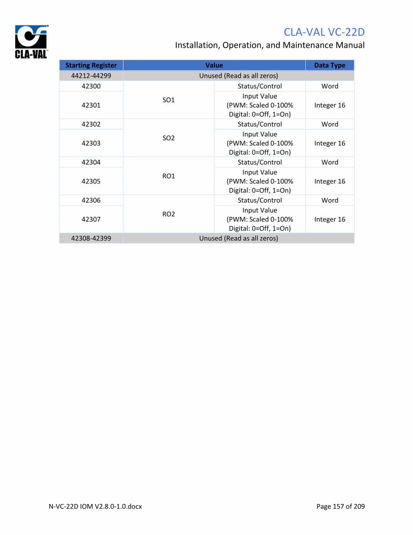
CLA-VAL VC-22D
Installation, Operation, and Maintenance Manual
N-VC-22D IOM V2.8.0-1.0.docx Page 157 of 209
Starting Register Value Data Type
44212-44299 Unused (Read as all zeros)
42300
SO1
Status/Control Word
42301 Input Value
(PWM: Scaled 0-100% Digital: 0=Off, 1=On)
Integer 16
42302
SO2
Status/Control Word
42303 Input Value
(PWM: Scaled 0-100% Digital: 0=Off, 1=On)
Integer 16
42304
RO1
Status/Control Word
42305 Input Value
(PWM: Scaled 0-100% Digital: 0=Off, 1=On)
Integer 16
42306
RO2
Status/Control Word
42307 Input Value
(PWM: Scaled 0-100% Digital: 0=Off, 1=On)
Integer 16
42308-42399 Unused (Read as all zeros)

CLA-VAL VC-22D
Installation, Operation, and Maintenance Manual
N-VC-22D IOM V2.8.0-1.0.docx Page 158 of 209
9.2.3.2 Status Control Word
Each bit in the status/control word holds status information about the IO point, or allows an override to
be applied. See the table below for a definition of each bit:
Bit # Description Applicability Access
0 Modbus override active All IO points Read/Write
1 Signal lost/out of range AI’s and DI_F’s only Read Only
2 Local override applied All IO points Read Only
3 Alarm active AO's, SO's, and RO's only Read Only
4 Recopy active AO's, SO's, and RO's only Read Only
5 Not used, always 0
6 Not used, always 0
7 Not used, always 0
8 Not used, always 0
9 Not used, always 0
10 Not used, always 0
11 Not used, always 0
12 Not used, always 0
13 Not used, always 0
14 Not used, always 0
15 Not used, always 0 Table 9.3
Some of the bits in TABLE 9.2 are not applicable for all IO points (e.g. bit 1 only is relevant for AI’s and
DI_F’s). The bit will always be zero when it’s not applicable to the current IO point.
9.2.3.3 IO Point Value
The second register holds the value for the IO point. Any decimal places in the IO point will be stored
using an implied decimal place in the IO point register. For example, if the variable has 2 decimal places
and the number for the IO point is 96.52, then the register will have value 9652. If the variable has 1
decimal place and the number of the IO point is 12.3, then the register will have value 123. See section
6.2.9.4 to configure number of decimal places associated with the IO point. The IO point value is read
only when the Modbus override is off and read/write when the Modbus override is on.
The IO point value stored in the Modbus register is identical to the value displayed on the VC-22D
display. The value will be scaled, filtered, and any overrides will be applied. If a loss of signal exists, the
loss of signal value will be stored in the IO point value register.
9.2.3.4 Modbus Override
To enable the Modbus override for a particular IO point, a 1 must be written to bit 0 of the
status/control word. The VC-22D will then accept override values written to the IO point value register.
This is different from the base Modbus registers because a 1 does not need to be written to the override
bit every time a new override value is issued.

CLA-VAL VC-22D
Installation, Operation, and Maintenance Manual
N-VC-22D IOM V2.8.0-1.0.docx Page 159 of 209
The Modbus override can be enabled using function code 06 or 16 that writes 1 to the status/control
word. An override value can then be written to the IO point value register in the same write or
subsequent writes.
To disable the Modbus override, write a 0 to bit 0 of the status/control word. The IO point value register
will then revert back to the value physically measured on the IO channel.
Appendix A: Standard ValvApp Library List The VC-22D comes with a standard library containing 17 ValvApps. The table below lists each standard
ValvApp and includes a brief description. Appendix B includes a worksheet for each ValvApp which
details each IO point and programming logic for the ValvApp. Appendix C includes an electrical wiring
diagram for each ValvApp.
When looking for a standard ValvApp, first review the description of each ValvApp and find one that
seems appropriate to your Cla-Valve application (pressure reducing, pressure sustaining, flow control,
…). Then, review the ValvApp’s worksheet and electrical schematic for the ValvApp you chose. Make
sure the ValvApp worksheet and electrical drawing include the same IO points that your Cla-Valve
application has, and make sure the logic fits your needs.
Name Description
131-Flow-Mag-V2.0 Valve Series: 131 Maintains a flow rate based on user entered setpoint. ValvApp requires an analog input from a flowmeter. The home screen graphically shows flowmeter as a mag meter upstream of the valve. Note: This is the same ValvApp as 131-Flow-X144D-V2.0, but graphics show mag meter instead of X144D flowmeter.
131-Flow-X144D-V2.0 Valve Series: 131 Maintains a flow rate based on user entered setpoint. ValvApp requires an analog input from a flowmeter. The home screen graphically shows an X144D flowmeter inserted into the valve’s sensing port. Note: This is the same ValvApp as 131-Flow-Mag-V2.0, but graphics show X144D flowmeter instead of mag meter.
131-LvlAltitude-L-V2.0 Valve Series: 131 Controls a fill valve to maintain tank level. If tank level is above a user entered setpoint, the valve goes full closed. If the tank level is below a user entered setpoint, the valve goes full open. This ValvApp requires an analog input from a level transducer.

CLA-VAL VC-22D
Installation, Operation, and Maintenance Manual
N-VC-22D IOM V2.8.0-1.0.docx Page 160 of 209
131-LvlMod-L+Mag-V2.0 Valve Series: 131 Controls a fill valve to maintain tank level. If tank level is above a user entered setpoint, the valve goes full closed. If the tank level is below a user entered setpoint, the valve maintains a flow rate into the tank. As the tank level drops, the flow rate is increased. ValvApp requires analog inputs from a level transducer and flowmeter. The home screen graphically shows flowmeter as a mag meter upstream of the valve. Note: This is the same ValvApp as 131-LvlMod-L+X144D-V2.0, but graphics show X144D flowmeter instead of mag meter.
131-LvlMod-L+X117D-V2.0 Valve Series: 131 Controls a fill valve to maintain tank level. If tank level is above a user entered setpoint, the valve goes full closed. If the tank level is below a user entered setpoint, the valve is opened to a certain position to fill the tank. As the tank level drops, the valve position will be increased. ValvApp requires a level transducer analog input and position transmitter analog input.
131-LvlMod-L+X144D-V2.0 Valve Series: 131 Controls a fill valve to maintain tank level. If tank level is above a user entered setpoint, the valve goes full closed. If the tank level is below a user entered setpoint, the valve is modulated to maintain a flow rate into the tank. The emptier the tank, the higher the flow rate used to fill the tank. ValvApp requires a level transducer analog input and flowmeter analog input. The home screen graphically shows an X144D flowmeter inserted into the valve’s sensing port. Note: This is the same ValvApp as 131-LvlMod-L+Mag-V2.0, but graphics show X144D flowmeter instead of mag meter.
131-Position-X117D-V2.0 Valve Series: 131 Maintains a valve position specified by a user setpoint. ValvApp requires a position transmitter analog input.
131-PressureReducing-P2-V2.0 Valve Series: 131 Reduces the downstream pressure to match a user setpoint. ValvApp requires a downstream pressure transmitter analog input.
131-PressureSustaining-P1-V2.0 Valve Series: 131 Sustains an upstream pressure to match a user setpoint. ValvApp requires an upstream pressure transmitter analog input.

CLA-VAL VC-22D
Installation, Operation, and Maintenance Manual
N-VC-22D IOM V2.8.0-1.0.docx Page 161 of 209
133-Flow-DP+Pos-V2.0 Valve Series: 133 Calculates the flow rate based on the valves differential pressure and position. Modulates the valve to maintain a user entered flowrate setpoint. ValvApp requires analog inputs from a DP meter and position transmitter.
133-Flow-P1+P2+X117D-V2.0 Valve Series: 133 Calculates the flow rate based on the valves differential pressure and position. Modulates the valve to maintain a user entered flowrate setpoint. ValvApp requires analog inputs from an upstream pressure transmitter, downstream pressure transmitter, and position transmitter.
342-Flow-Flw-V1.0 Valve Series: 342 Actuates a motor operated pilot which modulates a valve to maintain a flow rate. The flow rate is a user adjustable setpoint. ValvApp requires analog inputs from the motor’s position feedback and flowmeter. The flowmeter is not used for control, only for monitoring.
342-Flow-V1.0 Valve Series: 342 Actuates a motor operated pilot which modulates a valve to maintain a flow rate. The flow rate is a user adjustable setpoint. ValvApp requires an analog input from the motor’s position feedback.
350-PressureSustaining-P1-V1.0 Valve Series: 350 Actuates a motor operated pilot which modulates a valve to sustain an upstream pressure. The upstream pressure is a user adjustable setpoint. ValvApp requires analog inputs from the motor position feedback and upstream pressure transmitter. The upstream pressure transmitter is not user for control, only monitoring.
350-PressureSustaining-V1.0 Valve Series: 350 Actuates a motor operated pilot which modulates a valve to sustain an upstream pressure. The upstream pressure is a user adjustable setpoint. ValvApp requires an analog input from the motor position feedback. The upstream pressure transmitter is not user for control, only monitoring.
390-PressureReducing-P2-V1.0 Valve Series: 390 Actuates a motor operated pilot which modulates a valve to reduce a downstream pressure. The downstream pressure is a user adjustable setpoint. ValvApp requires analog inputs from the motor position

CLA-VAL VC-22D
Installation, Operation, and Maintenance Manual
N-VC-22D IOM V2.8.0-1.0.docx Page 162 of 209
feedback and downstream pressure transmitter. The downstream pressure transmitter is not user for control, only monitoring.
390-PressureReducing-V1.0 Valve Series: 390 Actuates a motor operated pilot which modulates a valve to reduce a downstream pressure. The downstream pressure is a user adjustable setpoint. ValvApp requires an analog input from the motor position feedback.

CLA-VAL VC-22D
Installation, Operation, and Maintenance Manual
N-VC-22D IOM V2.8.0-1.0.docx Page 163 of 209
Appendix B: Standard ValvApp Worksheets
B.1 131-Flow-Mag-V2.0 or 131-Flow-X144D-V2.0

CLA-VAL VC-22D
Installation, Operation, and Maintenance Manual
N-VC-22D IOM V2.8.0-1.0.docx Page 164 of 209

CLA-VAL VC-22D
Installation, Operation, and Maintenance Manual
N-VC-22D IOM V2.8.0-1.0.docx Page 165 of 209
B.2 131-LvlAltitude-L-V2.0

CLA-VAL VC-22D
Installation, Operation, and Maintenance Manual
N-VC-22D IOM V2.8.0-1.0.docx Page 166 of 209

CLA-VAL VC-22D
Installation, Operation, and Maintenance Manual
N-VC-22D IOM V2.8.0-1.0.docx Page 167 of 209
B.3 131-LvlMod-L+Mag-V2.0 or 131-LvlMod-L+144D-V2.0

CLA-VAL VC-22D
Installation, Operation, and Maintenance Manual
N-VC-22D IOM V2.8.0-1.0.docx Page 168 of 209

CLA-VAL VC-22D
Installation, Operation, and Maintenance Manual
N-VC-22D IOM V2.8.0-1.0.docx Page 169 of 209
B.4 131-LvlMod-L+X117D-V2.0

CLA-VAL VC-22D
Installation, Operation, and Maintenance Manual
N-VC-22D IOM V2.8.0-1.0.docx Page 170 of 209

CLA-VAL VC-22D
Installation, Operation, and Maintenance Manual
N-VC-22D IOM V2.8.0-1.0.docx Page 171 of 209
B.5 131-Position-X117D-V2.0

CLA-VAL VC-22D
Installation, Operation, and Maintenance Manual
N-VC-22D IOM V2.8.0-1.0.docx Page 172 of 209

CLA-VAL VC-22D
Installation, Operation, and Maintenance Manual
N-VC-22D IOM V2.8.0-1.0.docx Page 173 of 209
B.6 131-PressureReducing-P2-V2.0

CLA-VAL VC-22D
Installation, Operation, and Maintenance Manual
N-VC-22D IOM V2.8.0-1.0.docx Page 174 of 209
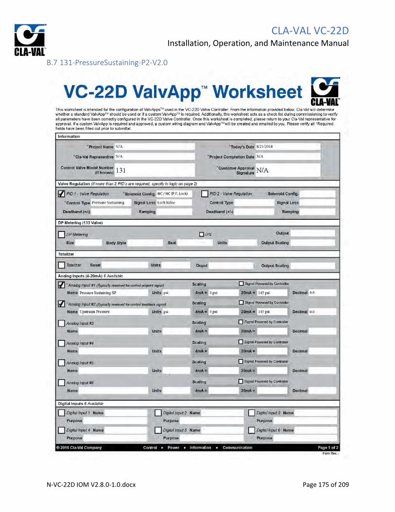
CLA-VAL VC-22D
Installation, Operation, and Maintenance Manual
N-VC-22D IOM V2.8.0-1.0.docx Page 175 of 209
B.7 131-PressureSustaining-P2-V2.0

CLA-VAL VC-22D
Installation, Operation, and Maintenance Manual
N-VC-22D IOM V2.8.0-1.0.docx Page 176 of 209

CLA-VAL VC-22D
Installation, Operation, and Maintenance Manual
N-VC-22D IOM V2.8.0-1.0.docx Page 177 of 209
B.8 133-Flow-DP+X117D-V2.0
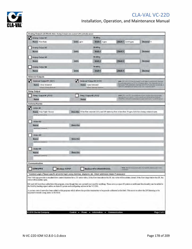
CLA-VAL VC-22D
Installation, Operation, and Maintenance Manual
N-VC-22D IOM V2.8.0-1.0.docx Page 178 of 209

CLA-VAL VC-22D
Installation, Operation, and Maintenance Manual
N-VC-22D IOM V2.8.0-1.0.docx Page 179 of 209
B.9 133-Flow-P1+P2+X117D-V2.0

CLA-VAL VC-22D
Installation, Operation, and Maintenance Manual
N-VC-22D IOM V2.8.0-1.0.docx Page 180 of 209

CLA-VAL VC-22D
Installation, Operation, and Maintenance Manual
N-VC-22D IOM V2.8.0-1.0.docx Page 181 of 209
B.10 340-Flow-Mag-V1.0

CLA-VAL VC-22D
Installation, Operation, and Maintenance Manual
N-VC-22D IOM V2.8.0-1.0.docx Page 182 of 209
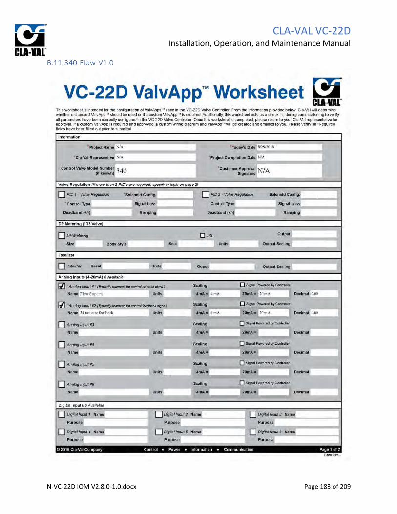
CLA-VAL VC-22D
Installation, Operation, and Maintenance Manual
N-VC-22D IOM V2.8.0-1.0.docx Page 183 of 209
B.11 340-Flow-V1.0

CLA-VAL VC-22D
Installation, Operation, and Maintenance Manual
N-VC-22D IOM V2.8.0-1.0.docx Page 184 of 209

CLA-VAL VC-22D
Installation, Operation, and Maintenance Manual
N-VC-22D IOM V2.8.0-1.0.docx Page 185 of 209
B.12 350-PressureSustaining-P1-V1.0

CLA-VAL VC-22D
Installation, Operation, and Maintenance Manual
N-VC-22D IOM V2.8.0-1.0.docx Page 186 of 209

CLA-VAL VC-22D
Installation, Operation, and Maintenance Manual
N-VC-22D IOM V2.8.0-1.0.docx Page 187 of 209
B.13 350-PressureSustaining-V1.0

CLA-VAL VC-22D
Installation, Operation, and Maintenance Manual
N-VC-22D IOM V2.8.0-1.0.docx Page 188 of 209

CLA-VAL VC-22D
Installation, Operation, and Maintenance Manual
N-VC-22D IOM V2.8.0-1.0.docx Page 189 of 209
B.14 390-PressureReducing-P1-V1.0

CLA-VAL VC-22D
Installation, Operation, and Maintenance Manual
N-VC-22D IOM V2.8.0-1.0.docx Page 190 of 209

CLA-VAL VC-22D
Installation, Operation, and Maintenance Manual
N-VC-22D IOM V2.8.0-1.0.docx Page 191 of 209
B.15 390-PressureReducing-V1.0

CLA-VAL VC-22D
Installation, Operation, and Maintenance Manual
N-VC-22D IOM V2.8.0-1.0.docx Page 192 of 209

CLA-VAL VC-22D
Installation, Operation, and Maintenance Manual
N-VC-22D IOM V2.8.0-1.0.docx Page 193 of 209
Appendix C: Standard ValvApp Wiring Diagrams
C.1 131-Flow-Mag-V2.0

CLA-VAL VC-22D
Installation, Operation, and Maintenance Manual
N-VC-22D IOM V2.8.0-1.0.docx Page 194 of 209
C.2 131-Flow-X144D-V2.0

CLA-VAL VC-22D
Installation, Operation, and Maintenance Manual
N-VC-22D IOM V2.8.0-1.0.docx Page 195 of 209
C.3 131-LvlAltitude-L-V2.0

CLA-VAL VC-22D
Installation, Operation, and Maintenance Manual
N-VC-22D IOM V2.8.0-1.0.docx Page 196 of 209
C.4 131-LvlMod-L+Mag-V2.0

CLA-VAL VC-22D
Installation, Operation, and Maintenance Manual
N-VC-22D IOM V2.8.0-1.0.docx Page 197 of 209
C.5 131-LvlMod-L+X117D-V2.0

CLA-VAL VC-22D
Installation, Operation, and Maintenance Manual
N-VC-22D IOM V2.8.0-1.0.docx Page 198 of 209
C.6 131-LvlMod-L+X144D-V2.0

CLA-VAL VC-22D
Installation, Operation, and Maintenance Manual
N-VC-22D IOM V2.8.0-1.0.docx Page 199 of 209
C.7 131-Position-X117D-V2.0

CLA-VAL VC-22D
Installation, Operation, and Maintenance Manual
N-VC-22D IOM V2.8.0-1.0.docx Page 200 of 209
C.8 131-PressureReducing-P2-V2.0

CLA-VAL VC-22D
Installation, Operation, and Maintenance Manual
N-VC-22D IOM V2.8.0-1.0.docx Page 201 of 209
C.9 131-PressureSustaining-P1-V2.0

CLA-VAL VC-22D
Installation, Operation, and Maintenance Manual
N-VC-22D IOM V2.8.0-1.0.docx Page 202 of 209
C.10 133-Flow-DP+X117D-V2.0

CLA-VAL VC-22D
Installation, Operation, and Maintenance Manual
N-VC-22D IOM V2.8.0-1.0.docx Page 203 of 209
C.11 133-Flow-P1+P2+X117D-V2.0

CLA-VAL VC-22D
Installation, Operation, and Maintenance Manual
N-VC-22D IOM V2.8.0-1.0.docx Page 204 of 209
C.12 340-Flow-Mag-V1.0

CLA-VAL VC-22D
Installation, Operation, and Maintenance Manual
N-VC-22D IOM V2.8.0-1.0.docx Page 205 of 209
C.13 340-Flow-V1.0

CLA-VAL VC-22D
Installation, Operation, and Maintenance Manual
N-VC-22D IOM V2.8.0-1.0.docx Page 206 of 209
C.14 350-PressureSustaining-P1-V1.0

CLA-VAL VC-22D
Installation, Operation, and Maintenance Manual
N-VC-22D IOM V2.8.0-1.0.docx Page 207 of 209
C.15 350-PressureSustaining-V1.0

CLA-VAL VC-22D
Installation, Operation, and Maintenance Manual
N-VC-22D IOM V2.8.0-1.0.docx Page 208 of 209
C.16 390-PressureReducing-P2-V1.0

CLA-VAL VC-22D
Installation, Operation, and Maintenance Manual
N-VC-22D IOM V2.8.0-1.0.docx Page 209 of 209
C.17 390-PressureReducing-V1.0