model ut601: operating manual
TRANSCRIPT
1
Model UT601: OPERATING MANUAL
Table of ContentsTitle PageOverviewUnpacking InspectionSafety InformationRules For Safe OperationInternational Electrical SymbolsThe Meter StructureFunctional ButtonsDisplay SymbolsMeasurement Operation A. Measuring Resistance B. Capacitance Measurement C. Diode and Continuity Test D. Transistor hFE MeasurementGeneral SpecificationsAccuracy Specifications A. Resistance Test B. Capacitance Test C. Continuity & Diodes D. TransistorMaintenance A. General Service B. Replacing the Battery C. Replacing the Fuse
345689910111113151718191920202122222324

2
Model UT601: OPERATING MANUAL
To avoid electric shock or personal injury, read the“Safety Information” and “Rules for Safety Operation”carefully before using the Meter.
Warning
3
Model UT601: OPERATING MANUAL
OverviewThis Operating Manual covers information on safety andcautions. Please read the relevant information carefullyand observe all the Warnings and Notes strictly.
Digital Capacitance Meter Model UT601 (hereafter referredto as “the Meter”) is a 3 1/2 digits with steady operations,fashionable design and highly reliable hand-held measuringinstrument. The Meter can also measure resistance,transistor, diode and continuity buzzer.
The Meter has a broad capacitance measurement rangeand precise accuracy. It can be used in measuring thecircuit designed capacitance of cable, switch and PCBlayout.
4
Model UT601: OPERATING MANUAL
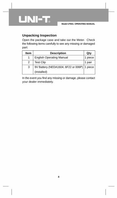
Unpacking InspectionOpen the package case and take out the Meter. Checkthe following items carefully to see any missing or damagedpart:
Item Description Qty1
2
3
English Operating Manual
Test Clip
9V Battery (NEDA1604, 6F22 or 006P)
(installed)
1 piece
1 pair
1 piece
In the event you find any missing or damage, please contactyour dealer immediately.
Safety InformationThis Meter complies with the standards EMC EN61326.
Use the Meter only as specified in this operating manual,otherwise the protection provided by the Meter may beimpaired.
In this manual, a Warning identifies conditions and actionsthat pose hazards to the user, or may damage the Meteror the equipment under test.
A Note identifies the information that user should payattention on.
International electrical symbols used on the Meter and inthis Operating Manual are explained on page 8.
5
Model UT601: OPERATING MANUAL
To avoid possible electric shock or personal injury,and to avoid possible damage to the Meter or to theequipment under test, adhere to the following rules:
Warning
Before using the Meter inspect the case. Do not usethe Meter if it is damaged or the case (or part of thecase) is removed. Look for cracks or missing plastic.Pay attention to the insulation around the connectors.Inspect the test clips for damaged insulation orexposed metal. Check the test clips for continuity.Replace damaged test clips with identical modelnumber or electrical specifications before using theMeter.Do not apply voltage to the Meter.The rotary switch should be placed in the rightposition and no any changeover of range shall bemade during measurement is conducted to preventdamage of the Meter.Do not apply more than 30Vrms between theterminals and the grounding to avoid electric shockand damage to the Meter.Use the proper terminals, function, and range foryour measurements.Do not use or store the Meter in an environment ofhigh temperature, humidity, explosive, inflammableand strong magnetic field. The performance of theMeter may deter iorate af ter dampened.Disconnect circuit power and discharge all high-voltage capacitors before testing resistance,continuity, capacitance or diodes.Replace the battery as soon as the battery indicator appears. With a low battery, the Meter mightproduce false readings that can lead to electric shockand personal injury.Remove test clips from the Meter and turn the Meterpower off before opening the Meter case.
l
l
ll
l
l
l
l
l
l
Rules For Safe Operation
6
Model UT601: OPERATING MANUAL
When servicing the Meter, use only the same modelnumber or identical electrical specificationsreplacement parts.The internal circuit of the Meter shall not be alteredat will to avoid damage of the Meter and any accident.Soft cloth and mild detergent should be used toclean the surface of the Meter when servicing. Noabrasive and solvent should be used to prevent thesurface of the Meter from corrosion, damage andaccident.The Meter is suitable for indoor use.Turn the Meter power off when it is not in use andtake out the battery when not using for a long time.Please constantly check the battery as it may leakwhen it has been using for some time, replace thebattery as soon as leaking appears. A leaking batterywill damage the Meter.
l
l
l
l
l
7
Model UT601: OPERATING MANUAL
8
Model UT601: OPERATING MANUAL
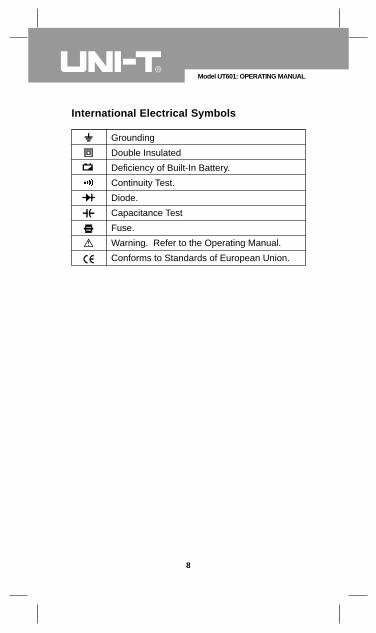
International Electrical Symbols
Grounding
Double Insulated
Deficiency of Built-In Battery.
Continuity Test.
Diode.
Capacitance Test
Fuse.
Warning. Refer to the Operating Manual.
Conforms to Standards of European Union.
9
Model UT601: OPERATING MANUAL
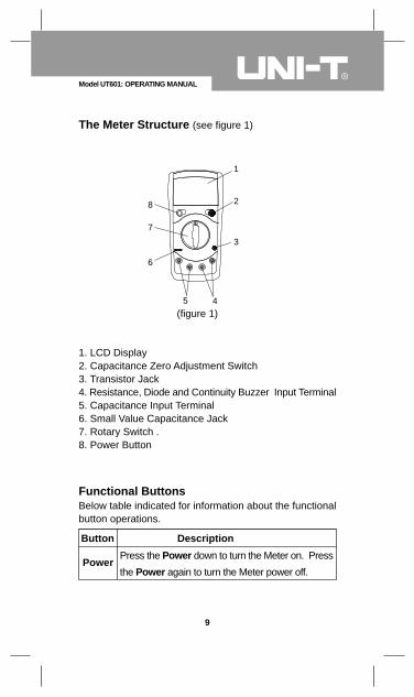
The Meter Structure (see figure 1)
Functional Buttons
1. LCD Display2. Capacitance Zero Adjustment Switch3. Transistor Jack4. Resistance, Diode and Continuity Buzzer Input Terminal5. Capacitance Input Terminal6. Small Value Capacitance Jack7. Rotary Switch .8. Power Button
(figure 1)
Below table indicated for information about the functionalbutton operations.
Button Description
Press the Power down to turn the Meter on. Press
the Power again to turn the Meter power off.Power
1
2
3
6
7
8
5 4
β
10
Model UT601: OPERATING MANUAL
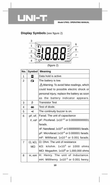
Display Symbols (see figure 2)
(figure 2)
Data hold is active.
The battery is low.
Warning: To avoid false readings, which
could lead to possible electric shock or
personal injury, replace the battery as soon
as the battery indicator appears.
Transistor Test
Test of diode.
The continuity buzzer is on.
Farad. The unit of capacitance
pF: Picofarad. 1x10-12 or 0.000000000001
farads.
nF: Nanofarad. 1x10⁻⁹ or 0.000000001 farads.
µF: Microfarad.1x10-6 or 0.000001 farads.
mF: Millifarad. 1x10⁻³ or 0.001 farads.
: Ohm. The unit of resistance
k : ki lohm. 1x10³ or 1000 ohms
M : Megaohm. 1x10⁶ or 1,000,000 ohms
H: Henry. The unit of Inductance.
mH: Millihenry. 1x10⁻³ or 0.001 henry.
No. Symbol Meaning
1
2
3
4
5
6
7
8
pF, nF,
F, mF
, k ,
M
H, mH
mFµFnFpF
mHΩH
kΩMΩ
3
1
2
5
4
6
8
7
Make sure the Low Battery Display is not on,otherwise false readings may be provided.Pay extra attention to the symbol, before carryingmeasurement, which is located besides the inputterminals of the Meter.
l
l
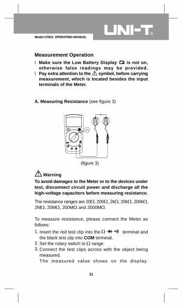
To avoid damages to the Meter or to the devices undertest, disconnect circuit power and discharge all thehigh-voltage capacitors before measuring resistance.
Warning
The resistance ranges are 20 , 200 , 2k , 20k , 200k ,2M , 20M , 200M and 2000M .
To measure resistance, please connect the Meter asfollows:
Insert the red test clip into the terminal andthe black test clip into COM terminal.Set the rotary switch to range.Connect the test clips across with the object beingmeasured.The measured value shows on the display.
1.
2.3.
11
Model UT601: OPERATING MANUAL
Measurement Operation
A. Measuring Resistance (see figure 3)
(figure 3)
When measuring at 20Ω and 200Ω range, the test clipscan add 0.1 to 0.3Ω error to resistance. To obtain precisereadings in these low-resistance measurement, that isthe range 20Ω and 200Ω, short circuit the input terminalsbeforehand and record the reading obtained (called thisreading as X). (X) is the additional resistance from thetest clips.Then use the equation:measured resistance value (Y) – (X) = precision readingsof resistance.The Meter displays “1” when there is no input, forexample, open circuit situation.For high resistance measurement (>1MΩ), it is normaltaking several seconds to obtain a stable reading.When resistance measurement has been completed,disconnect the connection between the testing clips andthe circuit under test and remove the testing clips awayfrom the input terminals of the Meter.
l
l
l
l
12
Model UT601: OPERATING MANUAL
Note
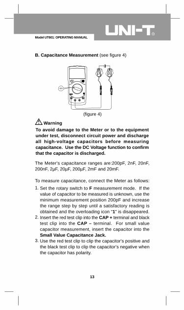
To avoid damage to the Meter or to the equipmentunder test, disconnect circuit power and dischargeall high-voltage capacitors before measuringcapacitance. Use the DC Voltage function to confirmthat the capacitor is discharged.
Warning
The Meter’s capacitance ranges are:200pF, 2nF, 20nF,200nF, 2µF, 20µF, 200µF, 2mF and 20mF.
To measure capacitance, connect the Meter as follows:
Set the rotary switch to F measurement mode. If thevalue of capacitor to be measured is unknown, use theminimum measurement position 200pF and increasethe range step by step until a satisfactory reading isobtained and the overloading icon “1” is disappeared.Insert the red test clip into the CAP + terminal and blacktest clip into the CAP – terminal. For small valuecapacitor measurement, insert the capacitor into theSmall Value Capacitance Jack.Use the red test clip to clip the capacitor’s positive andthe black test clip to clip the capacitor’s negative whenthe capacitor has polarity.
1.
2.
3.
13
Model UT601: OPERATING MANUAL
B. Capacitance Measurement (see figure 4)
(figure 4)
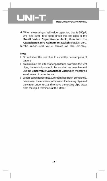
Do not short the test clips to avoid the consumption ofbattery.To minimize the effect of capacitance stored in the testclips, the test clips should be as short as possible anduse the Small Value Capacitance Jack when measuringsmall value of capacitance.When capacitance measurement has been completed,disconnect the connection between the testing clips andthe circuit under test and remove the testing clips awayfrom the input terminals of the Meter.
l
l
l
When measuring small value capacitor, that is 200pF,2nF and 20nF, first open circuit the test clips or theSmall Value Capacitance Jack, then turn theCapacitance Zero Adjustment Switch to adjust zero.The measured value shows on the display.
4.
5.
14
Model UT601: OPERATING MANUAL
Note
To avoid damages to the Meter or to the devices undertest, disconnect circuit power and discharge all thehigh-voltage capacitors before measuring diodes andcontinuity.
Testing Diodes
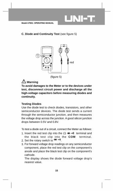
Warning
Use the diode test to check diodes, transistors, and othersemiconductor devices. The diode test sends a currentthrough the semiconductor junction, and then measuresthe voltage drop across the junction. A good silicon junctiondrops between 0.5V and 0.8V.
To test a diode out of a circuit, connect the Meter as follows:Insert the red test clip into the terminal andthe black test clip into the COM terminal.Set the rotary switch to .For forward voltage drop readings on any semiconductorcomponent, place the red test clip on the component’sanode and place the black test clip on the component’scathode.The display shows the diode forward voltage drop’snearest value.
1.
2.3.
15
Model UT601: OPERATING MANUAL
C. Diode and Continuity Test (see figure 5)
(figure 5)
red
In a circuit, a good diode should still produce a forwardvoltage drop reading of 0.5V to 0.8V; however, thereverse voltage drop reading can vary depending on theresistance of other pathways between the probe tips.Connect the test clips to the proper terminals as saidabove to avoid error display. The LCD will display “1”indicating open-circuit for wrong connection. The unit ofdiode is Volt (V), displaying the positive-connectionvoltage-drop value.When diode measurement has been completed,disconnect the connection between the testing clips andthe circuit under test and remove the testing clips awayfrom the input terminals of the Meter.
l
l
l
To test for continuity, connect the Meter as below:Insert the red test clip into the terminal andthe black test clip into the COM terminal.Set the rotary switch to .Connect the test clips across with the object beingmeasured.The beeper comes on continuously when the testresistance <120 .The Meter displays the value of the test resistance.
The LCD displays “1” indicating the circuit being testedis open.When continuity test has been completed, disconnectthe connection between the testing clips and the circuitunder test and remove the testing clips away from theinput terminals of the Meter.
l
l
16
Model UT601: OPERATING MANUAL
Note
Testing for Continuity
1.
2.3.
4.
5.
Note
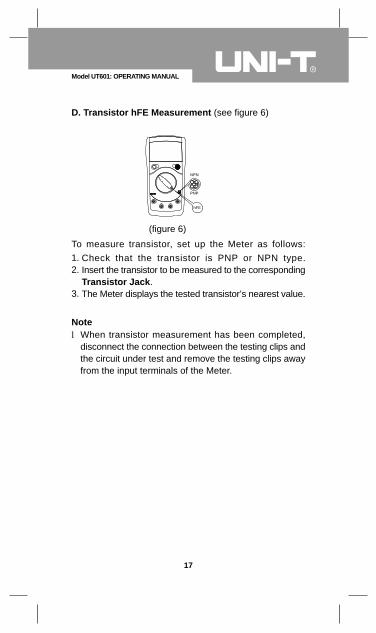
To measure transistor, set up the Meter as follows:Check that the transistor is PNP or NPN type.Insert the transistor to be measured to the correspondingTransistor Jack.The Meter displays the tested transistor’s nearest value.
When transistor measurement has been completed,disconnect the connection between the testing clips andthe circuit under test and remove the testing clips awayfrom the input terminals of the Meter.
l
17
Model UT601: OPERATING MANUAL
D. Transistor hFE Measurement (see figure 6)
(figure 6)
1.2.
3.
Note
NPN
PNP
hFE
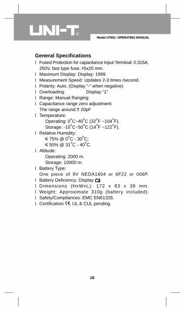
Fused Protection for capacitance Input Terminal: 0.315A,250V, fast type fuse, 5x20 mm.Maximum Display: Display: 1999.Measurement Speed: Updates 2-3 times /second.Polarity: Auto. (Display “-“ when negative)Overloading: Display “1”Range: Manual RangingCapacitance range zero adjustment:The range around 20pFTemperature:
Operating: 0oC~40oC (32oF ~104oF).Storage: -10oC~50oC (14oF ~122oF).
Relative Humidity: 75% @ 0oC - 30oC; 50% @ 31oC - 40oC.
Altitude: Operating: 2000 m.Storage: 10000 m.
Battery Type:One piece of 9V NEDA1604 or 6F22 or 006P.Battery Deficiency: DisplayDimensions (HxWxL): 172 x 83 x 38 mm.Weight: Approximate 310g (battery included).Safety/Compliances: EMC EN61326.Certification: , UL & CUL pending.
l
llllll
l
l
l
l
lllll
18
Model UT601: OPERATING MANUAL
General Specifications
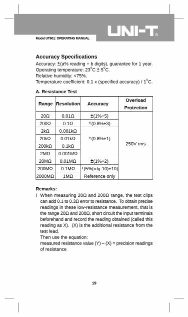
Accuracy: (a% reading + b digits), guarantee for 1 year.Operating temperature: 23oC 5oC.Relative humidity: <75%.Temperature coefficient: 0.1 x (specified accuracy) / 1oC.
When measuring 20Ω and 200Ω range, the test clipscan add 0.1 to 0.3Ω error to resistance. To obtain precisereadings in these low-resistance measurement, that isthe range 20Ω and 200Ω, short circuit the input terminalsbeforehand and record the reading obtained (called thisreading as X). (X) is the additional resistance from thetest lead.Then use the equation:measured resistance value (Y) – (X) = precision readingsof resistance
l
19
Model UT601: OPERATING MANUAL
Accuracy Specifications
A. Resistance Test
Range Resolution AccuracyOverload
Protection
20Ω200Ω2kΩ
20kΩ200kΩ2MΩ
20MΩ200MΩ
2000MΩ
0.01Ω0.1Ω
0.001kΩ0.01kΩ0.1kΩ
0.001MΩ0.01MΩ0.1MΩ1MΩ
(1%+5)
(0.8%+3)
(0.8%+1)
(1%+2)
[5%(rdg-10)+10]
Reference only
250V rms
Remarks:
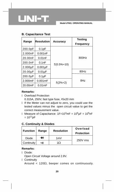
Overload Protection0.315A, 250V, fast type fuse, 5x20 mmIf the Meter can not adjust to zero, you could use thetested values minus the open circuit value to get thecorrect measurement value.Measure of Capacitance: 1F=103mF = 106µF = 109nF= 1012pF
l
l
l
Diode:Open Circuit Voltage around 2.8V.ContinuityAround < 120 , beeper comes on continuously.
l
l
20
Model UT601: OPERATING MANUAL
B. Capacitance Test
Range Resolution AccuracyTesting
Frequency
200.0pF
2.000nF
20.00nF
200.0nF
2.000µF
20.00µF
200.0µF
2.000mF
20.00mF
0.1pF
0.001nF
0.01nF
0.1nF
0.001µF
0.01µF
0.1µF
0.001mF
0.01mF
(0.5%+10)
(2%+2)
800Hz
80Hz
8Hz
Remarks:
C. Continuity & Diodes
Range ResolutionOverload
ProtectionFunction
Diode
Continuity
1mV
1250V rms
Remarks:
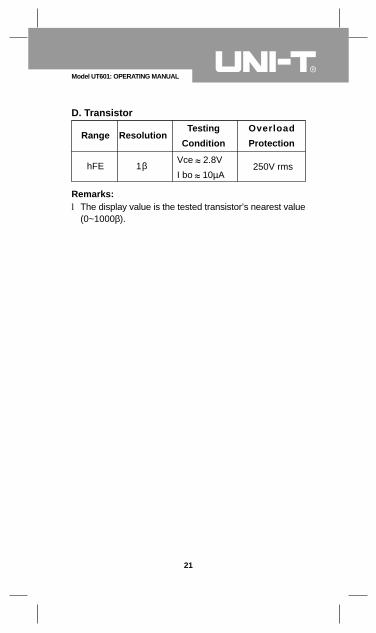
The display value is the tested transistor’s nearest value(0~1000β).l
21
Model UT601: OPERATING MANUAL
D. Transistor
Range ResolutionOverload
Protection
hFEVce 2.8V
I bo 10µA250V rms
Remarks:
Testing
Condition
1β
This section provides basic maintenance informationincluding battery and fuse replacement instruction.
Do not attempt to repair or service your Meter unlessyou are qualified to do so and have the relevantcalibration, performance test, and service information.
To avoid electrical shock or damage to the Meter, donot get water inside the case.
Warning
Periodically wipe the case with a damp cloth and milddetergent. Do not use abrasives or solvents.To clean the terminals with cotton bar with detergent, asdirt or moisture in the terminals can affect readings.Turn the Meter power off when it is not in use and takeout the battery when not using for a long time.Do not store the Meter in a place of humidity, hightemperature and strong magnetic field.
l
l
l
l
22
Model UT601: OPERATING MANUAL
Maintenance
A. General Service
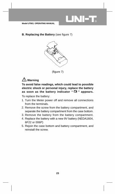
To avoid false readings, which could lead to possibleelectric shock or personal injury, replace the batteryas soon as the battery indicator “ ” appears.
Warning
Turn the Meter power off and remove all connectionsfrom the terminals.Remove the screw from the battery compartment, andseparate the battery compartment from the case bottom.Remove the battery from the battery compartment.Replace the battery with a new 9V battery (NEDA1604,6F22 or 006P)Rejoin the case bottom and battery compartment, andreinstall the screw.
1.
2.
3.4.
5.
23
Model UT601: OPERATING MANUAL
B. Replacing the Battery (see figure 7)
(figure 7)
To replace the battery:
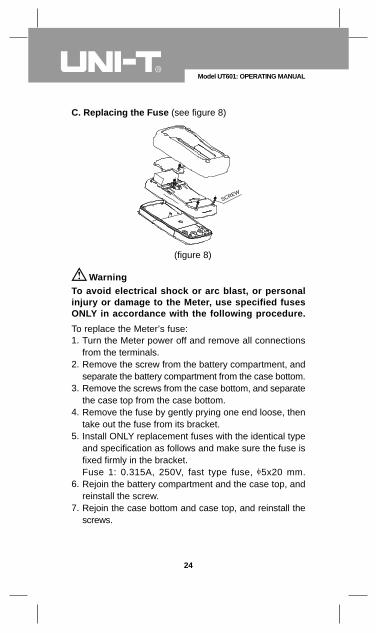
To avoid electrical shock or arc blast, or personalinjury or damage to the Meter, use specified fusesONLY in accordance with the following procedure.
Warning
To replace the Meter’s fuse:Turn the Meter power off and remove all connectionsfrom the terminals.Remove the screw from the battery compartment, andseparate the battery compartment from the case bottom.Remove the screws from the case bottom, and separatethe case top from the case bottom.Remove the fuse by gently prying one end loose, thentake out the fuse from its bracket.Install ONLY replacement fuses with the identical typeand specification as follows and make sure the fuse isfixed firmly in the bracket.Fuse 1: 0.315A, 250V, fast type fuse, 5x20 mm.Rejoin the battery compartment and the case top, andreinstall the screw.Rejoin the case bottom and case top, and reinstall thescrews.
1.
2.
3.
4.
5.
6.
7.
24
Model UT601: OPERATING MANUAL
C. Replacing the Fuse (see figure 8)
(figure 8)
SCREW
** END **
Replacement of the fuses is seldom required. Burning ofa fuse always results from improper operation.
25
Model UT601: OPERATING MANUAL