model test paper i - northern india engineering college pape… · the flag register in the 8051 is...
TRANSCRIPT

Northern India Engineering College, Delhi (GGSIP University)
SUBJECT – EMBEDDED SYSTEM SUBJECT CODE- ETEC-404
Manan Jani/ECE Dept./NIEC, Delhi
Model Test Paper –I
Note: Q. 1 is compulsory. Attempt one question from each unit. MM=75
Ques1.a) What does the term embedded system means? (5x5=25)
b) What is the main differences between Microprocessor and Microcontroller.
c) What is PSW register and explain the concept of stack in 8051?
d) SCON
e) interrupts in 8051
UNIT 1
(12.5)
Ques 2. What do you understand by Real Time System? Comment briefly on RTOS.
or
Ques 3. Explain interrupt routines in RTOS environment and handling of interrupt source calls.
UNIT I1
(12.5)
Ques 4 Explain the architecture of 8051 in deail.
or
Ques5. Explain the addresiing modes of 8051 in detail with suitable examples.
Northern India Engineering College, Delhi (GGSIP University)
SUBJECT – EMBEDDED SYSTEM SUBJECT CODE- ETEC-404
Manan Jani/ECE Dept./NIEC, Delhi
UNIT II1
(12.5)
Ques 6 Write a program to interface stepper Motor which will Rotate when External Interrupt
INT1 will Trigger.
or
Ques 7. Write a program to send data to port 1 of 8051 serially with 4800 baud rate.
UNIT 1V
(12.5)
Ques 8 Show the interface diagram that illustrates 8031 with External of 16KB of RAM and
16 KB of ROM?
or
Ques 9. Write a program, to send command and data to 2 line LCD.
ANSWERS:
Ans 1(a)
An embedded system is a computer system with a dedicated function within a larger mechanical
or electrical system, often with real-time computing constraints. It is embedded as part of a
complete device often including hardware and mechanical parts. By contrast, a general-purpose
computer, such as a personal computer (PC), is designed to be flexible and to meet a wide range
of end-user needs. Embedded systems control many devices in common use today. Modern
embedded systems are often based on microcontrollers (i.e. CPUs with integrated memory and/or
peripheral interfaces) but ordinary microprocessors (using external chips for memory and
peripheral interface circuits) are also still common, especially in more complex systems. In either
case, the processor(s) used may be types ranging from rather general purpose to very specialized
in certain class of computations, or even custom designed for the application at hand. A common
standard class of dedicated processors is the digital signal processor (DSP).

Northern India Engineering College, Delhi (GGSIP University)
SUBJECT – EMBEDDED SYSTEM SUBJECT CODE- ETEC-404
Manan Jani/ECE Dept./NIEC, Delhi
The key characteristic, however, is being dedicated to handle a particular task. Since the
embedded system is dedicated to specific tasks, design engineers can optimize it to reduce the
size and cost of the product and increase the reliability and performance. Some embedded
systems are mass-produced.
CHARACTERISTICS
a) Embedded systems are application specific & single functioned; application is known apriori,
the programs are executed repeatedly.
b) Efficiency is of paramount importance for embedded systems. They are optimized for energy,
code size, execution time, weight & dimensions, and cost.
c) Embedded systems are typically designed to meet real time constraints; a real time system
reacts to stimuli from the controlled object/ operator within the time interval dictated by the
environment. For real time systems, right answers arriving too late (or even too early) are wrong.
d) Embedded systems often interact (sense, manipulate & communicate) with external world
through sensors and actuators and hence are typically reactive systems; a reactive system is in
continual interaction with the environment and executes at a pace determined by that
environment.
e) They generally have minimal or no user interface.
Ans 1 (b)
Microprocessor Microprocessor Microcontroller Micro Controller
Microprocessor is heart of Computer system. Micro Controller is a heart of embedded system.
It is just a processor. Memory and I/O
components have to be connected externally
Micro controller has external processor along
with internal memory and I/O components
Since memory and I/O has to be connected
externally, the circuit becomes large.
Since memory and I/O are present internally,
the circuit is small.
Cannot be used in compact systems and hence
inefficient
Can be used in compact systems and hence it is
an efficient technique
Cost of the entire system increases Cost of the entire system is low
Due to external components, the entire power
consumption is high. Hence it is not suitable to
used with devices running on stored power like
batteries.
Since external components are low, total power
consumption is less and can be used with
devices running on stored power like batteries.
Northern India Engineering College, Delhi (GGSIP University)
SUBJECT – EMBEDDED SYSTEM SUBJECT CODE- ETEC-404
Manan Jani/ECE Dept./NIEC, Delhi
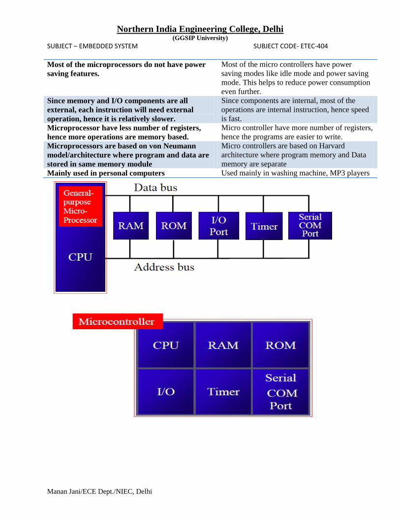
Most of the microprocessors do not have power
saving features.
Most of the micro controllers have power
saving modes like idle mode and power saving
mode. This helps to reduce power consumption
even further.
Since memory and I/O components are all
external, each instruction will need external
operation, hence it is relatively slower.
Since components are internal, most of the
operations are internal instruction, hence speed
is fast.
Microprocessor have less number of registers,
hence more operations are memory based.
Micro controller have more number of registers,
hence the programs are easier to write.
Microprocessors are based on von Neumann
model/architecture where program and data are
stored in same memory module
Micro controllers are based on Harvard
architecture where program memory and Data
memory are separate
Mainly used in personal computers Used mainly in washing machine, MP3 players
Northern India Engineering College, Delhi (GGSIP University)
SUBJECT – EMBEDDED SYSTEM SUBJECT CODE- ETEC-404
Manan Jani/ECE Dept./NIEC, Delhi
Ans 1(c )
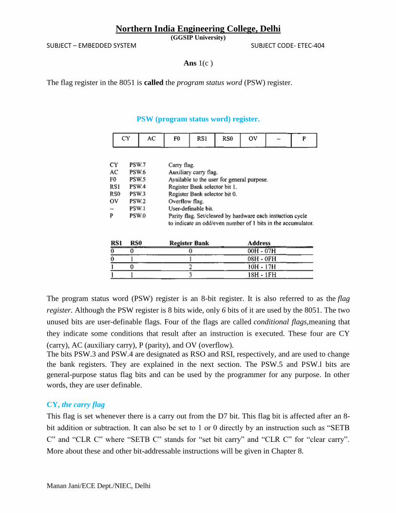
The flag register in the 8051 is called the program status word (PSW) register.
PSW (program status word) register.
The program status word (PSW) register is an 8-bit register. It is also referred to as the flag
register. Although the PSW register is 8 bits wide, only 6 bits of it are used by the 8051. The two
unused bits are user-definable flags. Four of the flags are called conditional flags,meaning that
they indicate some conditions that result after an instruction is executed. These four are CY
(carry), AC (auxiliary carry), P (parity), and OV (overflow).
The bits PSW.3 and PSW.4 are designated as RSO and RSI, respectively, and are used to change
the bank registers. They are explained in the next section. The PSW.5 and PSW.l bits are
general-purpose status flag bits and can be used by the programmer for any purpose. In other
words, they are user definable.
CY, the carry flag
This flag is set whenever there is a carry out from the D7 bit. This flag bit is affected after an 8-
bit addition or subtraction. It can also be set to 1 or 0 directly by an instruction such as “SETB
C” and “CLR C” where “SETB C” stands for “set bit carry” and “CLR C” for “clear carry”.
More about these and other bit-addressable instructions will be given in Chapter 8.

Northern India Engineering College, Delhi (GGSIP University)
SUBJECT – EMBEDDED SYSTEM SUBJECT CODE- ETEC-404
Manan Jani/ECE Dept./NIEC, Delhi
AC, the auxiliary carry flag
If there is a carry from D3 to D4 during an ADD or SUB operation, this bit is set; otherwise, it is
cleared. This flag is used by instructions that perform BCD (binary coded decimal) arithmetic.
See Chapter 6 for more information.
P, the parity flag
The parity flag reflects the number of 1 s in the A (accumulator) register only. If the A register
contains an odd number of Is, then P = 1. Therefore, P = 0 if A has an even number of Is.
OV, the overflow flag
This flag is set whenever the result of a signed number operation is too large, causing the high-
order bit to overflow into the sign bit. In general, the carry flag is used to detect errors in
unsigned arithmetic operations. The overflow flag is only used to detect errors in signed
arithmetic operations
Ans 1 (d)

Northern India Engineering College, Delhi (GGSIP University)
SUBJECT – EMBEDDED SYSTEM SUBJECT CODE- ETEC-404
Manan Jani/ECE Dept./NIEC, Delhi
Ans 1(e)
8051 Interrupts
The 8051 controller has six hardware interrupts of which five are available to the programmer.
These are as follows:

Northern India Engineering College, Delhi (GGSIP University)
SUBJECT – EMBEDDED SYSTEM SUBJECT CODE- ETEC-404
Manan Jani/ECE Dept./NIEC, Delhi
1. RESET interrupt - This is also known as Power on Reset (POR). When the RESET interrupt
is received, the controller restarts executing code from 0000H location. This is an interrupt which
is not available to or, better to say, need not be available to the programmer.
2. Timer interrupts - Each Timer is associated with a Timer interrupt. A timer interrupt notifies
the microcontroller that the corresponding Timer has finished counting.
3. External interrupts - There are two external interrupts EX0 and EX1 to serve external
devices. Both these interrupts are active low. In AT89C51, P3.2 (INT0) and P3.3 (INT1) pins are
available for external interrupts 0 and 1 respectively. An external interrupt notifies the
microcontroller that an external device needs its service.
4. Serial interrupt - This interrupt is used for serial communication. When enabled, it notifies
the controller whether a byte has been received or transmitted.
Ans.2
A Real-Time Operating System (RTOS) is a computing environment that reacts to input within
a specific time period. A real-time deadline can be so small that system reaction appears
instantaneous. The term real-time computing has also been used, however, to describe "slow
real-time" output that has a longer, but fixed, time limit.
Learning the difference between real-time and standard operating systems is as easy as
imagining yourself in a computer game. Each of the actions you take in the game is like a
program running in that environment. A game that has a real-time operating system for its
environment can feel like an extension of your body because you can count on a specific "lag
time:" the time between your request for action and the computer's noticeable execution of your
request. A standard operating system, however, may feel disjointed because the lag time is
unreliable. To achieve time reliability, real-time programs and their operating
system environment must prioritize deadline actualization before anything else. In the gaming
example, this might result in dropped frames or lower visual quality when reaction time and
visual effects conflict.
An operating system is considered real-time if it invariably enables its programs to perform tasks
within specific time constraints, usually those expected by the user. To meet this definition, some
or all of the following methods are employed:

Northern India Engineering College, Delhi (GGSIP University)
SUBJECT – EMBEDDED SYSTEM SUBJECT CODE- ETEC-404
Manan Jani/ECE Dept./NIEC, Delhi
The RTOS performs few tasks, thus ensuring that the tasks will always be executed
before the deadline
The RTOS drops or reduces certain functions when they cannot be executed within the
time constraints ("load shedding")
The RTOS monitors input consistently and in a timely manner
The RTOS monitors resources and can interrupt background processes as needed to
ensure real-time execution
The RTOS anticipates potential requests and frees enough of the system to allow timely
reaction to the user's request
The RTOS keeps track of how much of each resource (CPU time per timeslice, RAM,
communications bandwidth, etc.) might possibly be used in the worst-case by the currently-
running tasks, and refuses to accept a new task unless it "fits" in the remaining un-allocated
resources.
Ans 3.
ISRs in RTOS
ISRs have the higher priorities over the RTOS functions and the tasks.
An ISR should not wait for a semaphore, mailbox message or queue message
An ISR should not also wait for mutex else it has to wait for other critical section code to
finish before the critical codes in the ISR can run.
Only the IPC accept function for these events (semaphore, mailbox, queue) can be used, not
the post function
Direct Call to an ISR and ISR Enter message:
On an interrupt, the process running at the CPU is interrupted
ISR corresponding to that source starts executing.
A hardware source calls an ISR directly.
The ISR just sends an ISR enter message to the RTOS. ISR enter message is to inform
the RTOS that an ISR has taken control of the CPU

Northern India Engineering College, Delhi (GGSIP University)
SUBJECT – EMBEDDED SYSTEM SUBJECT CODE- ETEC-404
Manan Jani/ECE Dept./NIEC, Delhi
ISR IPC messages and Exit message
ISR code can send into a mailbox or message queue but the task waiting for a mailbox or
message queue does not start before the return from the ISR
When ISR finishes, it send s Exit message to OS.
On return from ISR by retrieving saved context, The RTOS later on returns to the
interrupted process (task) or reschedules the processes (tasks).
RTOS action depends on the event-messages, whether the task waiting for the event
message from the ISR is a task of higher priority than the interrupted task on the
interrupt.

Northern India Engineering College, Delhi (GGSIP University)
SUBJECT – EMBEDDED SYSTEM SUBJECT CODE- ETEC-404
Manan Jani/ECE Dept./NIEC, Delhi
RTOS interrupting on an interrupt :
On interrupt of a task, say, k-th task, the RTOS first gets itself the hardware source call
and initiates the corresponding ISR after saving the present processor status (or context)
Then the ISR during execution then can post one or more outputs for the events and
messages into the mailboxes or queues.
Ans 4.
As seen in figure below, the 8051 microcontroller has :
4 Kb of ROM
128b of RAM (including SFRs) satisfies the user's basic needs.
4 ports having in total of 32 input/output lines are in most cases sufficient to make all
necessary connections to peripheral environment.
The whole configuration is obviously thought of as to satisfy the needs of most programmers
working on development of automation devices. One of its advantages is that nothing is missing
and nothing is too much. In other words, it is created exactly in accordance to the average user‘s
taste and needs. Another advantages are RAM organization, the operation of Central Processor
Unit (CPU) and ports which completely use all recourses and enable further upgrade.

Northern India Engineering College, Delhi (GGSIP University)
SUBJECT – EMBEDDED SYSTEM SUBJECT CODE- ETEC-404
Manan Jani/ECE Dept./NIEC, Delhi
All 8051 microcontrollers have 4 I/O ports each comprising 8 bits which can be configured as
inputs or outputs. Accordingly, in total of 32 input/output pins enabling the microcontroller to be
connected to peripheral devices are available for use.
Pin configuration, i.e. whether it is to be configured as an input (1) or an output (0), depends on
its logic state. In order to configure a microcontroller pin as an output, it is necessary to apply a
logic zero (0) to appropriate I/O port bit. In this case, voltage level on appropriate pin will be 0.
Similarly, in order to configure a microcontroller pin as an input, it is necessary to apply a logic
one (1) to appropriate port. In this case, voltage level on appropriate pin will be 5V (as is the
case with any TTL input). This may seem confusing but don't loose your patience. It all becomes
clear after studying simple electronic circuits connected to an I/O pin.
Fig.Architecture of 8051

Northern India Engineering College, Delhi (GGSIP University)
SUBJECT – EMBEDDED SYSTEM SUBJECT CODE- ETEC-404
Manan Jani/ECE Dept./NIEC, Delhi
Ans 5.
Addressing mode is a way to address an operand. Operand means the data we are operating
upon (in most cases source data). It can be a direct address of memory, it can be register names,
it can be any numerical data etc.
There are 5 different ways to execute this instruction and hence we say, we have got 5 addressing
modes for 8051. They are 1) Immediate addressing mode 2) Direct addressing mode 3)Register
direct addressing mode 4) Register indirect addressing mode 5) Indexed addressing mode.
Immediate Addressing Mode
MOV A, #6AH
In general we can write MOV A, #data
This addressing mode is named as “immediate” because it transfers an 8-bit data immediately to
the accumulator (destination operand).
Direct Addressing Mode
This is another way of addressing an operand. Here the address of the data (source data ) is given
as operand. Lets take an example.
MOV A, 04H
Here 04H is the address of register 4 of register bank#0. When this instruction is executed, data
is stored in register 04H is moved to accumulator.
Register Direct Addressing Mode
In this addressing mode we use the register name directly (as source operand). An example is
shown below.
MOV A, R4
At a time registers can take value from R0,R1…to R7. You may already know there are 32 such
registers. Here comes the use of register banks. There are 4 register banks named 0,1,2 and 3.
Each bank has 8 registers named from R0 to R7. At a time only one register bank can be
selected. Selection of register bank is made possible through a Special Function Register (SFR)
named Processor Status Word (PSW).
Register Indirect Addressing Mode
So in this addressing mode, address of the data (source data to transfer) is given in the register
operand.
MOV A, @R0
Here the value inside R0 is considered as an address, which holds the data to be transferred to
accumulator.

Northern India Engineering College, Delhi (GGSIP University)
SUBJECT – EMBEDDED SYSTEM SUBJECT CODE- ETEC-404
Manan Jani/ECE Dept./NIEC, Delhi
Only R0 and R1 are allowed to form a register indirect addressing instruction. In other words
programmer must make any instruction either using @R0 or @R1. All register banks are
allowed.
Indexed Addressing Mode
MOVC A, @A+DPTR
where DPTR is data pointer. This is a 1 byte instruction with 2 cycles needed for execution.
The execution time required for this instruction is high compared to previous instructions (which
all were 1 cycle). The source operand is @A+DPTR and we know we will get the source data (to
transfer) from this location. It is nothing but adding contents of DPTR with present content of
accumulator. This addition will result a new data which is taken as the address of source data (to
transfer). The data at this address is then transferred to accumulator.
Ans 6

Northern India Engineering College, Delhi (GGSIP University)
SUBJECT – EMBEDDED SYSTEM SUBJECT CODE- ETEC-404
Manan Jani/ECE Dept./NIEC, Delhi
ORG 0000H
LJMP Main
;ISR for hardware interrupt INT1 to Rotate Steeper Motor
MOV A, #88H ; 10001000B
LOOP:
MOV P1, A
ACALL DELAY
RR A ; ROTATE BITS
SJMP LOOP
DELAY:
MOV TMOD, #01H
MOV TCON, #00H
MOV TL1, #0E0H
MOV TH0, #0B1H
SETB TR0
WAIT: JNB TF0, WAIT
RET
END
;Main Initilazation
ORG 30H
MAIN: MOV IE,#1000 0100 ;Enable External INT1
Here: SJMP HERE
END

Northern India Engineering College, Delhi (GGSIP University)
SUBJECT – EMBEDDED SYSTEM SUBJECT CODE- ETEC-404
Manan Jani/ECE Dept./NIEC, Delhi
Ans. 7

Northern India Engineering College, Delhi (GGSIP University)
SUBJECT – EMBEDDED SYSTEM SUBJECT CODE- ETEC-404
Manan Jani/ECE Dept./NIEC, Delhi
Ans.8
Northern India Engineering College, Delhi (GGSIP University)
SUBJECT – EMBEDDED SYSTEM SUBJECT CODE- ETEC-404
Manan Jani/ECE Dept./NIEC, Delhi
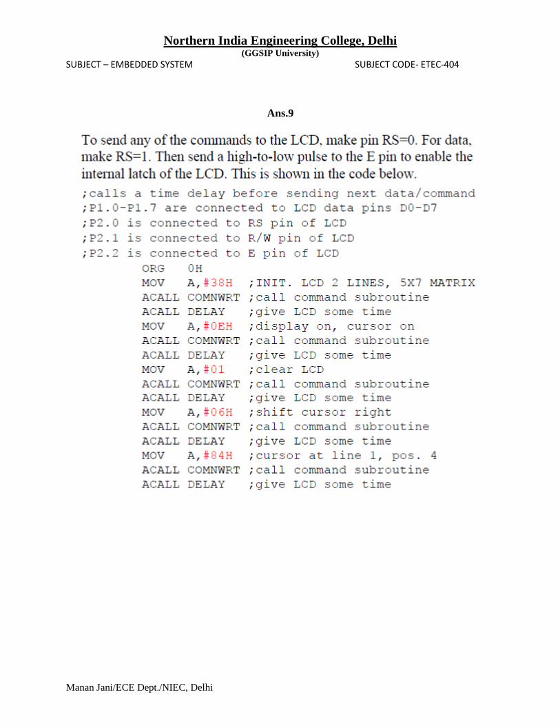
Ans.9

Northern India Engineering College, Delhi (GGSIP University)
SUBJECT – EMBEDDED SYSTEM SUBJECT CODE- ETEC-404
Manan Jani/ECE Dept./NIEC, Delhi