model swz - scag.com · model swz operator’s manual this manual contains the operating ... modelo...
TRANSCRIPT

MODEL SWZ
OPERATOR’S MANUAL
THIS MANUAL CONTAINS THE OPERATINGINSTRUCTIONS AND SAFETY INFORMA-TION FOR YOUR SCAG MOWER. READINGTHIS MANUAL CAN PROVIDE YOU WITHASSISTANCE IN MAINTENANCE AND AD-JUSTMENT PROCEDURES TO KEEP YOURMOWER PERFORMING TO MAXIMUM EFFI-CIENCY. THE SPECIFIC MODELS THAT THISBOOK COVERS ARE CONTAINED ON THEINSIDE COVER. BEFORE OPERATING YOURMACHINE, PLEASE READ ALL THE INFOR-MATION ENCLOSED.
PART NUMBER 03100
MODELO SWZ
MANUAL DE OPERADOR

This manual covers the operating instructions and illustrated parts list for:
SWZ36A-15KA with a serial number of 7370001 to 7379999SWZ48A-17KA with a serial number of 7380001 to 7389999SWZ52A-17KA with a serial number of 7390001 to 7399999SWZ-17KA with a serial number of 7430001 to 7439999SWZ-21KAE with a serial number of 7440001 to 7449999SWM-52A with a serial number of 7450001 to 7459999SWM-61A with a serial number of 7460001 to 7469999
Always use the entire serial number listed on the serial numbertag when referring to this product.
* Keep all shields in place, especially the grass discharge chute.* Before performing any maintenance or service, stop the machine and remove the spark plug wire and ignition key.* If a mechanism becomes clogged, stop the engine before cleaning.* Keep hands, feet and clothing away from power-driven parts.* Read this manual completely as well as other manuals that came with your mower.* Keep others off the tractor (only one person at a time)
FAILURE TO FOLLOW SAFE OPERATING PRACTICES MAY RESULT IN SERIOUS INJURY.
REMEMBER - YOUR MOWER IS ONLY AS SAFE AS THE OPERATOR!Hazard control and accident prevention are dependent upon the awareness,concern, prudence, and proper training of the personnel involved in theoperation, transport, maintenance, and storage of the equipment.
WARNING:

* Mantenga todas las protecciones en su lugar, especialmente el conducto dedescarga de césped.
* Antes de efectuar cualquier mantenimiento o servicio, apague la máquina y quiteel cable de la bujía y la llave de encendido.
* Si se obstruye algún mecanismo, apague el motor antes de limpiar la obstrucción. * Mantenga los pies, las manos y la ropa alejados de las partes móviles de la
máquina. * Lea completamente este manual, así como los demás manuales incluidos con
su cortacésped. * Mantenga a terceras personas fuera del tractor (sólo una persona a la vez).
EL NO SEGUIR PRÁCTICAS SEGURAS DE OPERACIÓNPUEDE PROVOCAR LESIONES GRAVES.
WARNING:ADVERTENCIA:
Este manual incluye las instrucciones de operación ylas listas ilustradas de piezas para:
SWZ36A-15KA con números de serie 7370001 al 7379999SWZ48A-17KA con números de serie 7380001 al 7389999SWZ52A-17KA con números de serie 7390001 al 7399999SWZ-17KA con números de serie 7430001 al 7439999SWZ-21KAE con números de serie 7440001 al 7449999SWM-52A con números de serie 7450001 al 7459999SWM-61A con números de serie 7460001 al 7469999
Siempre utilice todo el número de serie indicado en la etiqueta correspondientecuando haga referencia a este producto.
RECUERDE - ¡SU CORTACÉSPED SÓLO ES TAN SEGUROCOMO EL OPERADOR QUE LO MANEJE!
El control de riesgos y la prevención de accidentes dependende la conciencia, el interés, la prudencia y la capacitación
adecuados del personal involucrado en la operación,transporte, mantenimiento y almacenaje del equipo.

NOTES

TABLE OF CONTENTS
SUBJECT PAGE
Introduction .................................................................................................. 1General Safety Instructions .......................................................................... 1Signal Words ............................................................................................... 1Symbols ....................................................................................................... 2-3Before Operating ......................................................................................... 4While Operating ........................................................................................... 4Maintenance and Storage ........................................................................... 5Initial Run-In Procedures ............................................................................. 6Mower Operation ......................................................................................... 6Cutter Deck Belt Adjustments ...................................................................... 7Cutter Deck Adjustments ............................................................................. 8Blade Height Adjustments ........................................................................... 9Cutter Blades ............................................................................................... 9Neutral Adjustment ...................................................................................... 9Steering Control Rod Adjustment ................................................................ 10Tracking Adjustment .................................................................................... 10Parking Brake .............................................................................................. 11Lubrication and Maintenance Chart ............................................................ 12Troubleshooting Cutting Conditions ............................................................ 13-15Technical Specifications .............................................................................. 16-17
I
WE SUPPORT OPE
TECHNICIANCERTIFICATION

TABLE OF CONTENTS(CONTINUED)
SUBJECT PAGE
Illustrated Parts ListSWM-36A"Cutter Deck ..................................................................... 36-37SWM-48A", 52A", 61A", 72" Cutter Decks.............................................. 38-39Engine Deck................................................................................................ 40-41Drive And Brake Components.................................................................. 42-43Handle Assembly........................................................................................ 44-45Hydraulic Assembly .......................................................................... 46-47Hydraulic Pump Assembly ................................................................ 48-49Engine Deck Wire Harness-Kohler (Single Cyl.) 15KA & 17KA.......... 50Engine Deck Wire Harness- Kawasaki ............................................. 50Handle Wire Harness - Manual Start ................................................ 51Handle Wire Harness-Electric Start......................................................... 51Engine Deck Wire Harness-Kawasaki Electric Start ......................... 52Replacement Decals.................................................................................. 53-55Warranty Statement...............................................................Inside Back Cover
II

ÍNDICE
TEMA PÁGINA
Introducción ................................................................................................. 18Instrucciones generales de seguridad ......................................................... 18Palabras de señal ........................................................................................ 18Símbolos ..................................................................................................... 19-20Antes de operar ........................................................................................... 21Mientras opera ............................................................................................. 21Mantenimiento y almacenaje ....................................................................... 22Procedimientos de arranque inicial ............................................................. 23Operación del cortacésped ......................................................................... 23Ajustes de las correas de la plataforma de corte ......................................... 24Ajustes de la plataforma de corte ................................................................ 25Ajuste de altura de las cuchillas .................................................................. 26Cuchillas de corte ........................................................................................ 26Ajuste neutral............................................................................................... 26Ajuste de las varillas de control de dirección............................................... 27Ajuste de trayectoria .................................................................................... 27Freno de estacionamiento ........................................................................... 28Lubricación y mantenimiento ....................................................................... 29Identificación de fallas en las condiciones de corte..................................... 30-32Especificaciones técnicas ........................................................................... 33-34Notas .........................................................................................................................35
III
WE SUPPORT OPE
TECHNICIANCERTIFICATION

ÍNDICE(continuación)
TEMA PÁGINA
Listas ilustradas de piezasPlataforma de corte - SWM-36A .................................................................. 36-37Plataformas de corte - SWM-48A, -52A, -61A, -72....................................... 38-39Plataforma del motor.................................................................................... 40-41Componentes de transmisión y frenos ........................................................ 42-43Componentes de las manijas ...................................................................... 44-45Componentes hidráulicos ............................................................................ 46-47Bomba hidráulica ........................................................................................ 48-49Cableado de la plataforma del motor - Kohler (monocilíndrico) y 15-17KA . 50Cableado de la plataforma del motor - Kawasaki ........................................ 50Cableado de las manijas - Arranque manual .............................................. 51Cableado de las manijas - Arranque eléctrico (Kawasaki) .......................... 51Cableado de la plataforma del motor - Arranque eléctrico (Kawasaki) ........ 52Calcomanías de repuesto ............................................................................ 53-54Garantía .......................................................................................... Contraportada
IV

1
SIGNAL WORDS
This symbol means “Attention! Become Alert!Your Safety is Involved!" The symbol is usedwith the following signal words to attract yourattention to safety messages found on the decals andthroughout this manual. The message that followsthe symbol contains important information aboutsafety. To avoid injury and possible death, carefullyread the message! Be sure to fully understand thecauses of possible injury or death.
Signal Word:
It is a distinctive word on safety decals and through-out this manual that alerts the viewer to the existenceand relative degree of the hazard.
The signal word “DANGER” denotes that an ex-tremely hazardous situation exists on or near themachine that could result in high probability ofdeath or irreparable injury if proper precautions arenot taken.
The signal word “WARNING” denotes that a hazardexists on or near the machine that can result in injuryor death if proper precautions are not taken.
The signal word “CAUTION” is a reminder ofsafety practices on or near the machine that couldresult in personal injury if proper precautions arenot taken.
INTRODUCTION
Your mower was built to the highest standards in theindustry. However, the prolonged life and maxi-mum efficiency of your mower depends on youfollowing the operating, maintenance and adjust-ment instructions in this manual.
We encourage you to contact your dealer for repairs.All Scag dealers are informed of the latest methodsto service this equipment and provide prompt andefficient service in the field or at their service shop.They carry a full line of Scag service parts.
A replacement Operator's Manual is available fromyour Scag Servicing Dealer or by contacting ScagPower Equipment, Service Department, at P.O. Box152, Mayville, WI 53050. Please indicate thecomplete model and serial number of your Scagproduct.
USE OF OTHER THAN ORIGINAL SCAGREPLACEMENT PARTS WILL VOID THEWARRANTY.
The “Right” and “Left”, “Front” and “Rear” of themachine are referenced from the operator’s perspec-tive when in the normal operating position andfacing the forward travel direction.
GENERAL SAFETY INSTRUCTIONS
READ THIS OPERATOR'S MANUAL andinstructions furnished with attachments.
Perform only those maintenance procedures de-scribed in this manual. If major repairs are everneeded or assistance is desired, contact an Author-ized Scag Dealer. To ensure optimum performanceand safety, always purchase genuine SCAG replace-ment parts and accessories.
Your safety and the safety of others depends signifi-cantly upon your knowledge and understanding ofall correct operating practices and procedures of thismachine.
WARNING:
CAUTION:

2
CE Mark
TransmissionChoke
On/Start Spring Tension on Idler
OilOff/Stop
SYMBOL DESCRIPTIONSYMBOL DESCRIPTION
ISO Symbols
Spinning Blade
48071S
Parking Brake
WARNINGFALLING HAZARD
USE ONLY SCAG APPROVEDRIDING ATTACHMENTS
SEE OPERATOR'S MANUAL 481109
Falling Hazard

3
SlowFast
Cutting element - Engage
Cutting element - Basic symbol
Cutting element - Disengage
Continuously variable - Linear
Read operator's manualKeep bystanders away
Pinch Point
481039S
SYMBOL DESCRIPTION SYMBOL DESCRIPTION
Hourmeter/elapsed operating hours

4
BEFORE OPERATING
1. Know the controls and how to stop quickly.
2. Do not allow children to operate the machine.Do not allow adults to operate the machinewithout proper instruction.
3. Remove all debris or other objects that might bepicked up and thrown by the cutter blades. Keepall bystanders away from the mowing area.
4. Keep all shields, safety devices, and decals inplace. If a shield, safety device or decal isdefective or damaged, repair or replace it beforeoperating. Also, check all nuts, bolts and screwsfor proper tightness, to assure the machine is insafe operating condition.
5. Do not operate the machine while wearingsandals, tennis shoes, sneakers or shorts. Also,do not wear loose fitting clothing which couldget caught in moving parts. Always wear longpants and substantial shoes. Wearing safetyglasses and safety shoes is advisable and requiredby some local ordinances and insurance regula-tions.
6. Fill the fuel tank with clean, fresh gasoline, witha minimum octane rating of 87. Avoid spillinggasoline. Gasoline is highly flammable, handle itcarefully.A. Use an approved gasoline container.B. Do not fill the tank while the engine is hot or
running.C. Do not smoke while handling gasoline.D. Fill the fuel tank outdoors and up to approxi-
mately 1" (25 mm) below the bottom of thefiller neck.
E. Wipe up any spilled gasoline.
7. Before attempting to start the engine, move thespeed adjustment lever into the neutral position,move the blade engagement switch to the OFFposition, apply the parking brake, and move theneutral latches to neutral.
WHILE OPERATING
1. Start the engine when the neutral latches are inthe neutral lock position, the cutter blades aredisengaged, the parking brake is on and thespeed adjustment lever is in the neutral position.
2. Do not run the engine in a confined area withoutadequate ventilation. Exhaust fumes are hazard-ous and could possibly be deadly.
3. Using the machine demands attention. Toprevent loss of control:A. Mow only in daylight or when there is good
artificial light.B. Watch for holes or other hidden hazards.C. Do not drive close to a drop-off, ditch, creek
bank, or other hazard.D. Reduce speed when making sharp turns and
when turning on hillsides.E. Always be sure of your footing. Keep a firm
hold on the handles and walk---never run.F. Do not operate where conditions are slippery.
4. The discharge chute must always be installed andin the down position on the side discharge cutterdeck except when the Scag optional grasscatcher or mulching plate are properly installed.If the discharge area should plug, shut the engineoff and wait for all movement to stop beforeremoving the obstruction.
5. Disengage the blades and wait for them to stopbefore crossing gravel drives, walks or roads.
6. Shut the engine off and wait until the bladescome to a complete stop before removing thegrass catcher container.
7. Never raise the cutter deck while the blades arerotating.
8. Always park the mower and/or start the engineon a level surface. Apply the parking brake toprevent the mower from moving when you arenot in the operator’s position.
5
13. Do not pass or stand on the grass discharge sideof any mower with the engine running. Stopoperation when another person approaches.
9. If the cutting blades should strike a solid object orthe equipment should start to vibrate abnormally,stop the engine, disconnect the spark plug wire, andcheck immediately for the cause. Vibration isgenerally a warning of trouble. Check the machinefor damaged or defective parts. Repair any damagebefore starting the engine or operating the cutterdeck. Be sure the blades are in good condition andthe blade bolts are tight.
10. Reduce speed and exercise extreme caution onslopes and in sharp turns to prevent tipping orloss of control. Be especially cautious whenchanging directions on slopes.
DO NOT operate on steep slopes. To check aslope, attempt to back up it (with the cutter deckdown). If the machine can back up the slopewithout the wheels slipping, reduce speed anduse extreme caution. ALWAYS FOLLOW OSHAAPPROVED OPERATION.
11. Do not touch the engine or muffler while theengine is running or soon after it is stopped.These areas could be hot enough to cause a burn.
12. Before leaving the operator’s position or leavingthe mower unattended, move the speed adjust-ment lever into the neutral position, place theneutral latches in the neutral lock position, applythe parking brake, and move the blade engage-ment switch to OFF. Shut the engine OFF andremove the key.
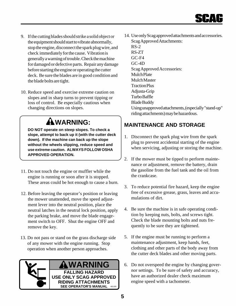
14. Use only Scag approved attachments and accessories.Scag Approved Attachments:RS-2RS-ZTGC-F4GC-4DScag Approved Accessories:Mulch PlateMulch MasterTraction PlusAdjusta-GripTurbo BaffleBlade BuddyUsing unapproved attachments, (especially "stand-up"riding attachments) may be hazardous.
MAINTENANCE AND STORAGE
1. Disconnect the spark plug wire from the sparkplug to prevent accidental starting of the enginewhen servicing, adjusting or storing the machine.
2. If the mower must be tipped to perform mainte-nance or adjustment, remove the battery, drainthe gasoline from the fuel tank and the oil fromthe crankcase.
3. To reduce potential fire hazard, keep the enginefree of excessive grease, grass, leaves and accu-mulations of dirt.
4. Be sure the machine is in safe operating condi-tion by keeping nuts, bolts, and screws tight.Check the blade mounting bolts and nuts fre-quently to be sure they are tightened.
5. If the engine must be running to perform amaintenance adjustment, keep hands, feet,clothing and other parts of the body away fromthe cutter deck blades and other moving parts.
6. Do not overspeed the engine by changing gover-nor settings. To be sure of safety and accuracy,have an authorized dealer check maximumengine speed with a tachometer.
WARNING:
WARNINGFALLING HAZARD
USE ONLY SCAG APPROVEDRIDING ATTACHMENTS
SEE OPERATOR'S MANUAL 481109

6
5. Check the safety switches for proper adjustment:
* The engine should crank and start if themachine is in neutral, the PTO engagementswitch is OFF and the parking brake is ON.
6. Apply lubricant to all the grease fittings. Lubricantwas applied at the factory. This is just aprecautionary check to make sure that all thefittings have been lubricated.
7. The engine must be shut off before checking the oilor adding oil to the crankcase.
8. Allow the engine to cool before storing the mower inany enclosure such as a garage or storage shed.Make sure the fuel tank is empty if the machine is tobe stored in excess of 30 days. Do not store themower near any open flame or where gasoline fumesmay be ignited by a spark.
9. Always store gasoline in a safety-approved, redcontainer.
10. Be careful when servicing the battery as itcontains acid, which is corrosive and could causeburns to skin and clothing.
11. Batteries release explosive gases when beingcharged or discharged. Keep batteries awayfrom any source of sparks and/or flame.
12. Make sure all hydraulic connections are tight andall hydraulic hoses and lines are in good condi-tion before starting the machine.
13. Hydraulic fluid is under high pressure. If youneed service on your hydraulic system, pleasesee your authorized Scag dealer.
INITIAL RUN-IN PROCEDURES(FIRST DAY OF USE OR APPROXI-MATELY 10 HOURS)
1. Check the belts for proper tension at 2, 4 and 8hours. Adjust as needed.
2. Check the steering control rods and the speedcontrol for neutral adjustment. (See Adjustments, page 6-8)
3. Check the tires for proper pressure.Caster Wheels 25 psi.Drive Wheels 15 psi.
4. Check for loose hardware. Tighten as needed.
MOWER OPERATION
-NOTE-Use gasoline with an octane rating no less than87.
* The speed adjustment lever must be inNEUTRAL.
* The blade clutch switch must be in the OFFposition.
* The neutral latches must be in the neutrallock position.
* The key switch must be on.* The parking brake must be on.
3. Start the engine:
* Choke as required. If the engine is cold, pullthe choke knob out. When the engine starts,slowly push the choke in. If the enginestalls, repeat the above operation. When theengine is warm, choking may not be necessary.
1. Read and understand the safety instructionsbefore attempting to operate this machine.
2. Before starting the engine:
* Check the oil level in the engine and thehydraulic reservoir.
* Fill the fuel tank with clean, fresh, lead-free gasoline.
* Open the fuel valve on the bottom of thefuel tank.
7
-NOTE-When PTO is engaged or (possibly) disengaged,a squealing sound from the underside of themachine is normal. It is caused by the electricclutch plates meshing as the mower comes up tospeed. For best equipment life, engage theclutch with the engine at 3/4 throttle, not underfull load.
If you are not familiar with the operation of thehydrostatic drive and zero turn feature, practiceturning and maneuvering with the hand controlsbefore engaging the blades.
5. Release the parking brake. Move the speedadjustment lever to the desired mowing speed.
-NOTE-Top speed is suggested only for transport!
6. While squeezing the steering brake levers with bothhands, release both neutral latches.
ire pressure can be adjusted for
WARNING:
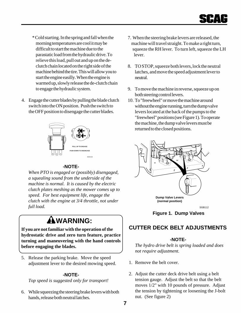
Dump Valve Levers(normal position)
SGB112
Figure 1. Dump Valves
CUTTER DECK BELT ADJUSTMENTS
-NOTE-The hydro drive belt is spring loaded and doesnot require adjustment.
1. Remove the belt cover.
2. Adjust the cutter deck drive belt using a belttension gauge. Adjust the belt so that the beltmoves 1/2" with 10 pounds of pressure. Adjustthe tension by tightening or loosening the J-boltnut. (See figure 2)
390S0138
PULL UP TO ENGAGE
PUSH DOWN TO DISENGAGE
7. When the steering brake levers are released, the machine will travel straight. To make a right turn, squeeze the RH lever. To turn left, squeeze the LH lever.
8. TO STOP, squeeze both levers, lock the neutrallatches, and move the speed adjustment lever toneutral.
9. To move the machine in reverse, squeeze up onboth steering control levers.
10. To "freewheel" or move the machine aroundwithout the engine running, turn the dump valvelevers located at the back of the pumps to the"freewheel" positions (see Figure 1). To operatethe machine, the dump valve levers must bereturned to the closed positions.
* Cold starting. In the spring and fall when themorning temperatures are cool it may bedifficult to start the machine due to theparastatic load from the hydraulic drive. Torelieve this load, pull out and up on the de-clutch chain located on the right side of themachine behind the tire. This will allow you tostart the engine easilly. When the engine iswarmed up, slowly release the de-clutch chainto engage the hydraulic system.
4. Engage the cutter blades by pulling the blade clutchswitch into the ON position. Push the switch tothe OFF position to disengage the cutter blades.

8
-NOTE-Due to initial belt stretch and to prevent the beltfrom slipping, check this adjustment after thefirst 2 hours, 4 hours and 8 hours of operation.
3. Adjust the RH blade drive belt using a belttension gauge. Adjust the belt so that the beltmoves 1/2" with 10 pounds of pressure. Adjustthe tension by tightening or loosening the J-bolt nut.(See figure 3)
4. Replace the belt cover.
"J" Bolt
Nut
Belt
Deck
Washer
Figure 3. Cutter Deck Belt Adjustment R.H.
SC405G
LOW CUT (1 3/4"- 3")
HIGH CUT (3 1/4"- 4 1/2")
MID RANGE(2 1/2"- 3 3/4")
CUTTER DECK HEIGHT ADJUSTMENT
Figure 4. Cutting Height Adjustment
Caster spacers also can be repositioned to changecutting heights and to change the pitch of the deck.(See figure 5)
Figure 5. Caster Wheel Spacers
CUTTER DECK ADJUSTMENTS
Due to the many cutting conditions that exist, it isdifficult to suggest a cutter deck setting that willwork for every lawn. There are two adjustments thatcan be made on these decks, pitch and height.
Pin
Spacers
2002SGB005
SC400G
BELT
WASHER
"J" BOLTNUT
CUTTER DECK DRIVE BELT TENSIONALIGNMENT IDLER - L.H.
END OF L-SHAPEDBRACKET
Figure 2. Deck Drive Belt Adjustment
PITCH is the angle of the blades (comparing front torear). A 1/4" downward pitch (front of deck down) isrecommended for best cutting performance.
HEIGHT is the nominal distance the blade is off of theground. This measurement is made with the bladespointed side to side and distance is measured betweencutting tip and ground. (Also see Blade Height Adjust-ment)
Changes to the cutting height can be achieved byrepositioning the cutter deck. (This adjustment will alsoeffect the pitch of the deck). There are three availablepositions (see figure 4).
9
CUTTER BLADES
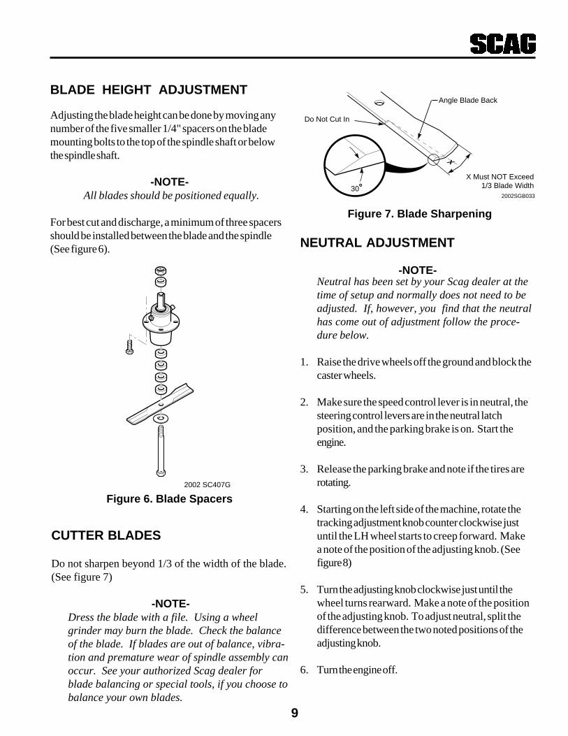
Do not sharpen beyond 1/3 of the width of the blade.(See figure 7)
-NOTE-Dress the blade with a file. Using a wheelgrinder may burn the blade. Check the balanceof the blade. If blades are out of balance, vibra-tion and premature wear of spindle assembly canoccur. See your authorized Scag dealer forblade balancing or special tools, if you choose tobalance your own blades.
Figure 6. Blade Spacers
NEUTRAL ADJUSTMENT
2002SGB033
Angle Blade Back
Do Not Cut In
X Must NOT Exceed1/3 Blade Width
X
30
2002 SC407G
Figure 7. Blade Sharpening
BLADE HEIGHT ADJUSTMENT
Adjusting the blade height can be done by moving anynumber of the five smaller 1/4" spacers on the blademounting bolts to the top of the spindle shaft or belowthe spindle shaft.
-NOTE-All blades should be positioned equally.
For best cut and discharge, a minimum of three spacersshould be installed between the blade and the spindle(See figure 6).
Neutral has been set by your Scag dealer at thetime of setup and normally does not need to beadjusted. If, however, you find that the neutralhas come out of adjustment follow the proce-dure below.
1. Raise the drive wheels off the ground and block thecaster wheels.
2. Make sure the speed control lever is in neutral, thesteering control levers are in the neutral latchposition, and the parking brake is on. Start theengine.
3. Release the parking brake and note if the tires arerotating.
4. Starting on the left side of the machine, rotate thetracking adjustment knob counter clockwise justuntil the LH wheel starts to creep forward. Makea note of the position of the adjusting knob. (Seefigure 8)
5. Turn the adjusting knob clockwise just until thewheel turns rearward. Make a note of the positionof the adjusting knob. To adjust neutral, split thedifference between the two noted positions of theadjusting knob.
6. Turn the engine off.
-NOTE-

10
481878
SLOWFAST
TRACKINGADJUSTMENTSEE OPERATOR'S
MANUAL
Figure 6. Tracking Adjustment
STEERING CONTROL RODADJUSTMENT
-NOTE-This adjustment is made to allow the steeringcontrol levers to be moved out of the neutrallatch without engaging reverse.
Before making this adjustment be sure that thespeed control bearing is just touching the speedcontrol cam and that the bellcrank bearing isresting in the center groove of the neutral cam.
1. Remove the speed control spring. Remove thesteering control rod swivel hair pin. Check thelocation of the swivel in the slotted hole in the bellcrank .
2. Turn the swivel joint on the steering control rodsuntil the swivel joint is centered in the slot in thebellcrank.
3. Reinstall the speed control spring onto the swivel.Install the hair pin onto the swivel.
Figure 5. Control Rod Adjustment
481878
SLOW
FAST
TRACKING
ADJUSTMENT
SEE OPERATOR'S
MANUAL
390s0198
Center ofSlot
Figure 8. Neutral Adjustment
481878
SLOWFAST
TRACKINGADJUSTMENTSEE OPERATOR'S
MANUAL
TRACKING ADJUSTMENT
-NOTE-Before proceeding with this adjustment, be surethat the tire pressures are correct. (see page 4)and that the neutral adjustment and the steeringcontrol rod adjustment have been completed.
1. With the machine on a flat level surface, start theengine and place the speed adjustment lever into thespeed that will most often be used.
2. Squeeze the steering control levers and release theneutral latch. Slowly release the steering controllevers, allowing the machine to move forward.
3. If the machine pulls to one side, turn the trackingadjustment knob on the slower side counter clock-wise until the machine tracks straight(see Figure 6).
4. Bring the steering control levers back to the neutrallock position and check to see that the machinedoes not creep forward on the adjusted wheel.
5. If the machine creeps in neutral you have moved outof the neutral band and will have to turn the trackingadjustment knob clockwise until the machine doesnot creep.
6. Repeat steps 1 and 2. If the machine pulls to oneside, turn the tracking adjustment knob on the fasterside clockwise until the machine tracks straight.
8. If tracking cannot be achieved, contact your Scagservicing dealer.

11
CAUTION:
PARKING BRAKE
1. Adjust the parking brake so that when the brakehand lever is against the stop on the handle bar, thebrake levers on the brake shaft weldment areagainst the stops on the engine deck.
Adjust the brake only enough to hold themachine. Excessive force may cause damageto the machine or brake components.
2. Adjust the brake actuator rod on either side of themachine to obtain proper brake adjustment.
12
COMMENTSPROCEDURE
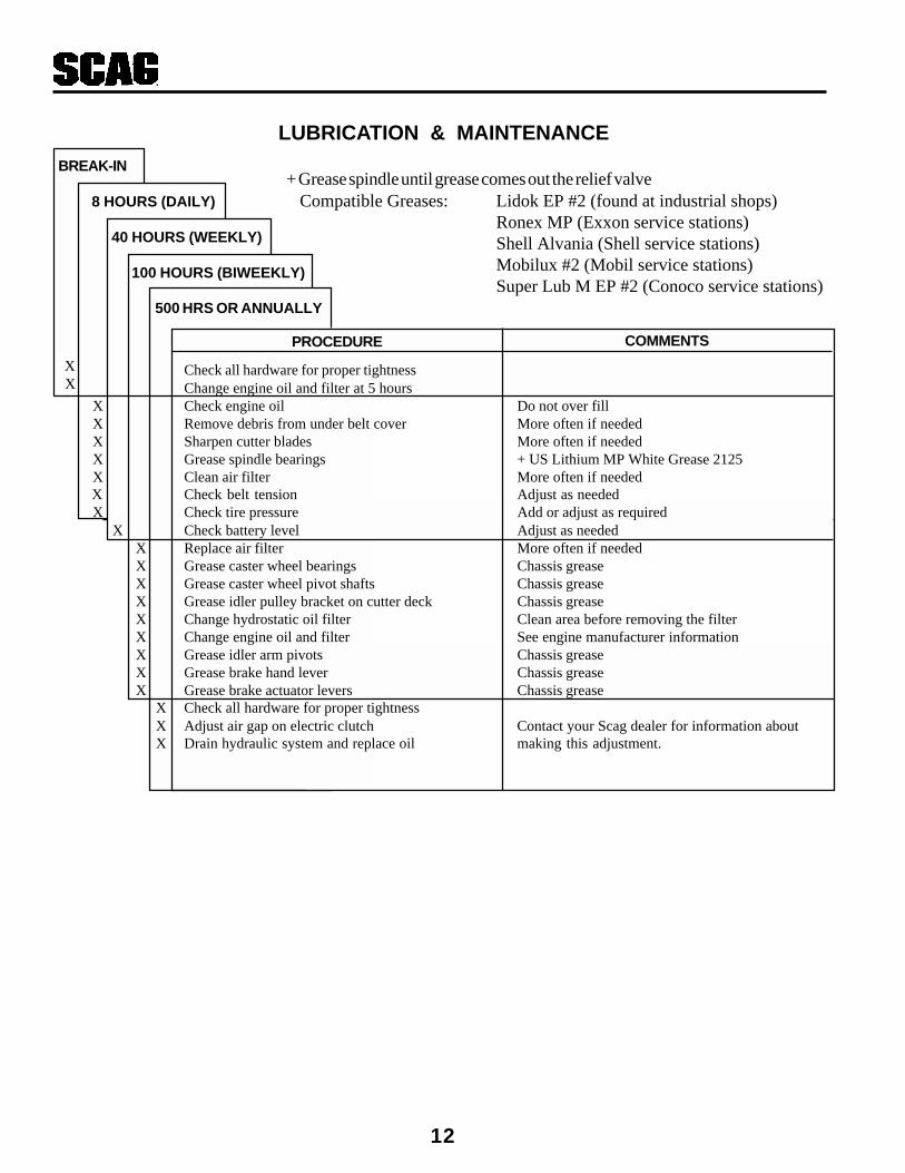
LUBRICATION & MAINTENANCE
+ Grease spindle until grease comes out the relief valveCompatible Greases: Lidok EP #2 (found at industrial shops)
Ronex MP (Exxon service stations)Shell Alvania (Shell service stations)Mobilux #2 (Mobil service stations)Super Lub M EP #2 (Conoco service stations)
XX Check all hardware for proper tightness
Change engine oil and filter at 5 hoursX Check engine oil Do not over fillX Remove debris from under belt cover More often if neededX Sharpen cutter blades More often if neededX Grease spindle bearings + US Lithium MP White Grease 2125X Clean air filter More often if needed
X Check belt tension Adjust as neededX Check tire pressure Add or adjust as required
X Check battery level Adjust as neededX Replace air filter More often if neededX Grease caster wheel bearings Chassis greaseX Grease caster wheel pivot shafts Chassis greaseX Grease idler pulley bracket on cutter deck Chassis greaseX Change hydrostatic oil filter Clean area before removing the filterX Change engine oil and filter See engine manufacturer informationX Grease idler arm pivots Chassis greaseX Grease brake hand lever Chassis greaseX Grease brake actuator levers Chassis grease
X Check all hardware for proper tightnessX Adjust air gap on electric clutch Contact your Scag dealer for information aboutX Drain hydraulic system and replace oil making this adjustment.
BREAK-IN
8 HOURS (DAILY)
40 HOURS (WEEKLY)
100 HOURS (BIWEEKLY)
500 HRS OR ANNUALLY

13
Stringers - Occasional Low engine RPM Run engine at full 3600 RPMBlades of UncutGrass Ground speed too fast Slow speed to adjust for conditions
Wet grass Cut grass after it has dried out
Dull blades, incorrect sharpening Sharpen blades
Deck plugged, grass accumulation Clean underside of deck
Belt slipping Adjust belt tension
Streaking - Strips of Dull, worn blades Sharpen bladesUncut Grass in CuttingPath Incorrect blade sharpening Sharpen blades
Low engine RPM Run engine at full 3600 RPM
Belt slipping Adjust belt tension
Deck plugged, grass accumulation Clean underside of deck
Ground speed too fast Slow speed to adjust for conditions
Wet grass Cut grass after it has dried out
Bent blades Replace bladesWidth of Deck
SGB018
CONDITION CAUSE CURE
Width of Deck
SGB020
Width of
Deck
Width of
DeckSGB019
Streaking - Strips of Not enough overlapping Increase the overlap of eachUncut Grass Between between rows passCutting Paths
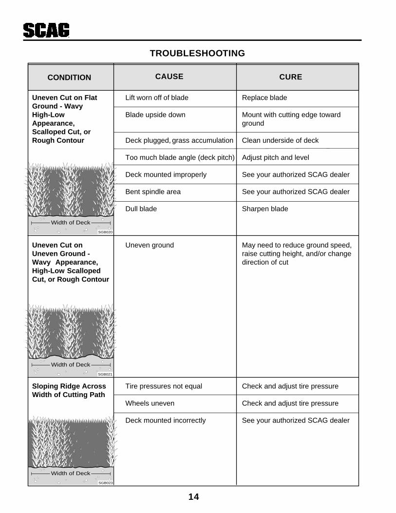
TROUBLESHOOTING CUTTING CONDITIONS
14
CONDITION
TROUBLESHOOTING
CAUSE CURE
Sloping Ridge Across Tire pressures not equal Check and adjust tire pressureWidth of Cutting Path
Wheels uneven Check and adjust tire pressure
Deck mounted incorrectly See your authorized SCAG dealer
Uneven Cut on Flat Lift worn off of blade Replace bladeGround - WavyHigh-Low Blade upside down Mount with cutting edge towardAppearance, groundScalloped Cut, orRough Contour Deck plugged, grass accumulation Clean underside of deck
Too much blade angle (deck pitch) Adjust pitch and level
Deck mounted improperly See your authorized SCAG dealer
Bent spindle area See your authorized SCAG dealer
Dull blade Sharpen blade
Uneven Cut on Uneven ground May need to reduce ground speed,Uneven Ground - raise cutting height, and/or changeWavy Appearance, direction of cutHigh-Low ScallopedCut, or Rough Contour
Width of Deck
SGB020
Width of Deck
SGB021
Width of Deck
SGB023

15
Scalping - Blades Low tire pressures Check and adjust pressuresHitting Dirt orCutting Very Close to Ground speed too fast Slow speed to adjust for conditionsthe Ground
Cutting too low May need to reduce ground speed,raise cutting height, change directionof cut, and/or change pitch and level
Rough terrain May need to reduce ground speed,raise cutting height, and/or changedirection of cut
Ground speed too fast Slow speed to adjust for conditions
Wet grass Cut grass after it has dried out
Step Cut Blades not mounted evenly Adjust pitch and levelRidge in Center ofCutting Path Bent blade Replace blade
Internal spindle failure See your authorized SCAG dealer
Mounting of spindle incorrect See your authorized SCAG dealer
Slope Cut - Sloping Bent spindle mounting area See your authorized SCAG dealerRidges Across Widthof Cutting Path Internal spindle failure See your authorized SCAG dealer
Bent deck housing See your authorized SCAG dealer
TROUBLESHOOTING
CONDITION CAUSE CURE
Width of Deck
SGB024
Width of Deck
SGB025
Width of Deck
SGB022

16
TECHNICAL SPECIFICATIONS
ENGINESGeneral Type: Heavy duty industrial/commercialBrand: Kohler, Kawasaki,Models: Kohler CV15T, Kaw. FC420V (14HP),FH451V (15HP),
FH500V (17HP)Horsepower: Kohler 15HP; Kaw. 14HP; Kaw. 15HP; Kaw. 17HPType: 4 cycle gas, vertical shaft enginesDisplacement: Kohler: 15HP = 426cc
Kawasaki: 14HP = 423cc, 17HP = 494ccCylinders: Varied - see manufacturer's specificationsGovernor: Mechanical type governor with variable speed control set
at 3600 rpm (+75 rpm), idle set at 1200 rpm (+75 rpm)Exhaust Group: Single exhaust canister mufflerFuel Pump Group: Varied - See manufacturer's specificationsOil Pump Group: Varied - See manufacturer's specificationsValve Group: Varied - See manufacturer's specificationsStarter/Electrical: Electronic Ignition with recoil starter or 12 volt battery with
alternator, solid state ignition with key startCharging System: 15 amp
ENGINE DECKThickness: 7 gauge steelFuel Tank: 5 gallon (19.0 litres) seamless polyethyleneDrive Wheels/Tires: 16x6.50-8 four-ply pneumatic tubeless, radius edgeBrakes: Dynamic braking through hydro drive systemAxles: 1" taperedHandle Bars: 1-1/4" diameter
DRIVE SYSTEMType: Hydro drive with two variable displacement pumps and two
cast-iron high torque motorsHydro Pumps: Two Hydro-Gear Model BDP 10L pumps with dump valves for
movement without running the engineDrive Wheel Motors: Two 12 cu. inch cast-iron high torque motorsHydro Fluid Cooling Group: 4qt. capacity cooling radiator, uses, SAE 20W50 fluid and
10 micron filterSteering / Travel Control:: Independent handle controls for each wheel, squeeze to move
from forward to neutral to reverse, neutral lock lever, speedrange controlled with single lever (patented design), in-fieldtracking adjustment with no tools necessary
Parking Brakes: 7.5" drum, band brake, one on each wheelDump Valves: Allows for movement without engine runningAxles: 1" tapered motor shaftsWire Harness: 14 gauge wireSafety Group: Handle actuated operator presence system (patented design),
blade / clutch and transmission interlock to engine kill
Forward Speed Range: 0 to 7.4 mphReverse Speed Range: 0 to 3.0 mph
Date of Issue: April , 2001Specifications Subject to Change Without Notice
17
TECHNICAL SPECIFICATIONS (CON'T)
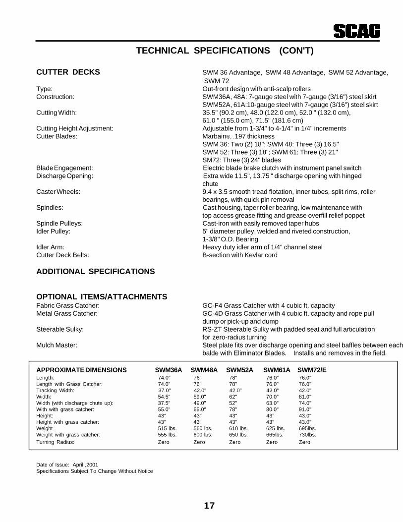
CUTTER DECKS SWM 36 Advantage, SWM 48 Advantage, SWM 52 Advantage, SWM 72
Type: Out-front design with anti-scalp rollersConstruction: SWM36A, 48A: 7-gauge steel with 7-gauge (3/16") steel skirt
SWM52A, 61A:10-gauge steel with 7-gauge (3/16") steel skirtCutting Width: 35.5" (90.2 cm), 48.0 (122.0 cm), 52.0 " (132.0 cm),
61.0 " (155.0 cm), 71.5" (181.6 cm)Cutting Height Adjustment: Adjustable from 1-3/4" to 4-1/4" in 1/4" incrementsCutter Blades: Marbain®, .197 thickness
SWM 36: Two (2) 18"; SWM 48: Three (3) 16.5"SWM 52: Three (3) 18"; SWM 61: Three (3) 21"SM72: Three (3) 24" blades
Blade Engagement: Electric blade brake clutch with instrument panel switchDischarge Opening: Extra wide 11.5", 13.75 " discharge opening with hinged
chuteCaster Wheels: 9.4 x 3.5 smooth tread flotation, inner tubes, split rims, roller
bearings, with quick pin removalSpindles: Cast housing, taper roller bearing, low maintenance with
top access grease fitting and grease overfill relief poppetSpindle Pulleys: Cast-iron with easily removed taper hubsIdler Pulley: 5" diameter pulley, welded and riveted construction,
1-3/8" O.D. BearingIdler Arm: Heavy duty idler arm of 1/4" channel steelCutter Deck Belts: B-section with Kevlar cord
ADDITIONAL SPECIFICATIONS
OPTIONAL ITEMS/ATTACHMENTSFabric Grass Catcher: GC-F4 Grass Catcher with 4 cubic ft. capacityMetal Grass Catcher: GC-4D Grass Catcher with 4 cubic ft. capacity and rope pull
dump or pick-up and dumpSteerable Sulky: RS-ZT Steerable Sulky with padded seat and full articulation
for zero-radius turningMulch Master: Steel plate fits over discharge opening and steel baffles between each
balde with Eliminator Blades. Installs and removes in the field.
APPROXIMATE DIMENSIONS SWM36A SWM48A SWM52A SWM61A SWM72/ELength: 74.0" 76" 78" 76.0" 76.0"Length with Grass Catcher: 74.0" 76" 78" 76.0" 76.0"Tracking Width: 37.0" 42.0" 42.0" 42.0" 42.0"Width: 54.5" 59.0" 62" 70.0" 81.0"Width (with discharge chute up): 37.5" 49.0" 52" 63.0" 74.0"With with grass catcher: 55.0" 65.0" 78" 80.0" 91.0"Height: 43" 43" 43" 43" 43.0"Height with grass catcher: 43" 43" 43" 43" 43.0"Weight 515 lbs. 560 lbs. 610 lbs. 625 lbs. 695lbs.Weight with grass catcher: 555 lbs. 600 lbs. 650 lbs. 665lbs. 730lbs.Turning Radius: Zero Zero Zero Zero Zero
Date of Issue: April ,2001Specifications Subject To Change Without Notice

18
PALABRAS DE SEÑAL
Este símbolo significa “¡Atención! ¡Esté alerta! ¡Suseguridad está en juego!” El símbolo se usa con lassiguientes palabras de señal para atraer su atención a losmensajes de seguridad que se encuentran en lascalcomanías y a lo largo de este manual. El mensaje quesigue al símbolo contiene información importante sobreseguridad. ¡Para evitar posibles lesiones o la muerte, leadetalladamente el mensaje! Cerciórese de entendercompletamente las causas que pueden ocasionar lesioneso la muerte.
Palabra de señal:
Es una palabra distintiva en las calcomanías de seguridad ya lo largo de este manual para alertar a la persona de laexistencia de los distintos grados relativos de riesgo.
La palabra de señal “DANGER” (PELIGRO) indica queexiste una situación de extremo riesgo en o cerca de lamáquina, que puede dar como resultado un alta proba-bilidad de muerte o lesión irreparable si no se toman lasprecauciones adecuadas.
La palabra de señal “WARNING” (ADVERTENCIA)indica que existe un riesgo en o cerca de la máquina quepuede ocasionar lesiones o la muerte si no se toman lasprecauciones debidas.
La palabra de señal “CAUTION” (PRECAUCIÓN) esun recordatorio de que se deben seguir prácticas segurasen o cerca de la máquina y que de no seguirse, se puedenocasionar lesiones personales.
INTRODUCCIÓN
Su cortacésped se fabricó según las normas más altas de laindustria. Sin embargo, la duración de la vida útil y el logrode la máxima eficiencia de su cortacésped dependen deque se sigan las instrucciones de operación, mantenimientoy ajuste indicados en este manual.
Le sugerimos que se ponga en contacto con sudistribuidor cuando necesite reparaciones. Todos losdistribuidores Scag están informados de los últimosmétodos para dar servicio a este equipo y paraproporcionar un servicio oportuno y eficiente en el sitiode trabajo o en el taller de servicio. Ellos cuentan con lalínea completa de refacciones Scag.
Su distribuidor Scag cuenta con un manual del operador derepuesto o se puede pedir uno escribiendo a: Scag PowerEquipment, Service Department, P.O. Box 152, Mayville,WI 53050, USA. Por favor indique el número completo demodelo y número de serie de su producto Scag.
EL USAR REFACCIONES Y ACCESORIOSQUE NO SEAN ORIGINALES DE SCAGINVALIDARÁ LA GARANTÍA.
Los lados “derecho”, “izquierdo”, “frente” y “atrás” de lamáquina son referencias desde la perspectiva del operadorcuando se halle en posición normal de funcionamiento enla dirección de desplazamiento hacia adelante.
INSTRUCCIONES GENERALESDE SEGURIDAD
LEA ESTE MANUAL DEL OPERADOR y lasinstrucciones proporcionadas con los accesorios.
Efectúe sólo los procedimientos de mantenimientodescritos en este manual. Si alguna vez se necesitanreparaciones mayores o si desea asesoría, póngase encontacto con un distribuidor autorizado Scag. Paragarantizar un rendimiento y seguridad óptimos, siempreadquiera refacciones y accesorios Scag.
Su seguridad y la de los demás dependen en mucho queusted conozca y comprenda todos los procedimientos y lasprácticas de operación correcta de esta máquina.
WARNING:
CAUTION:
PELIGRO:
ADVERTENCIA:
PRECAUCIÓN:

19
Marca de la CE
TransmisiónAhogador
Encendido/Arranque Tensión del resorte en la polea
AceiteApagado/Parar
SÍMBOLO DESCRIPCIÓNSÍMBOLO DESCRIPCIÓN
Símbolos de la ISO
Cuchilla giratoria
48071S
Freno de estacionamiento
WARNINGFALLING HAZARD
USE ONLY SCAG APPROVEDRIDING ATTACHMENTS
SEE OPERATOR'S MANUAL 481109
Riesgo de caer
20
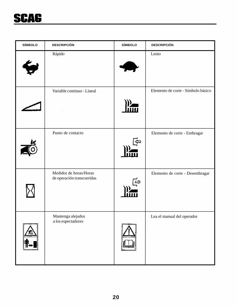
LentoRápido
Elemento de corte - Embragar
Elemento de corte - Símbolo básico
Elemento de corte - Desembragar
Variable continuo - Lineal
Lea el manual del operadorMantenga alejadosa los espectadores
Punto de contacto
481039S
SÍMBOLO DESCRIPCIÓN SÍMBOLO DESCRIPCIÓN
Medidor de horas/Horasde operación transcurridas

21
ANTES DE OPERAR
1. Conozca los controles y cómo detenerse rápidamente.
2. No permita que los niños operen la máquina. Nopermita que adultos sin la capacitación adecuadaoperen la máquina.
3. Retire todos los desechos u otros objetos que lascuchillas de corte pudieran levantar y arrojar.Mantenga alejados a los espectadores del área detrabajo.
4. Mantenga todas las protecciones, dispositivos deseguridad y calcomanías en su lugar. Si unaprotección, dispositivo de seguridad o calcomaníaestá defectuoso o dañado, repárelo o reempláceloantes de hacer funcionar la máquina. Además, reviseque estén correctamente apretados todos los tornillos,tuercas y pernos para garantizar que la máquina estéen condiciones seguras de operación.
5. No opera la máquina cuando use sandalias, zapatostenis, calzado deportivo o pantalón corto. Nunca useropa holgada que podría enredarse en las partesmóviles de la máquina. Use siempre pantalón largo yzapatos macizos. Se aconseja usar lentes y calzado deseguridad, y esto es requisito de algunos reglamentoslocales y estipulaciones de las compañías de seguro.
6. Llene el tanque de combustible con gasolina limpia yfresca, con un octanaje no menor a 87. Evite derramarla gasolina. Maneje la gasolina con cuidado: es muyinflamable.
A. Use un recipiente aprobado para gasolina.
B. No llene el tanque mientras el motor está calienteo funcionando.
C. No fume mientras maneja gasolina.
D. Llene el tanque de combustible al aire libre y hastaaproximadamente 1 pulgada por debajo del cuellode llenado.
E. Limpie la gasolina derramada.
7. Antes de intentar arrancar el motor, mueva la palancade ajuste de velocidad a la posición neutral, mueva elinterruptor de accionamiento de las cuchillas a laposición de apagado, aplique el freno de estaciona-miento y mueva los seguros neutrales a la posición deenclavamiento en neutral.
MIENTRAS OPERA
1. Arranque el motor con los seguros neutrales en laposición de enclavamiento en neutral, las cuchillas decorte apagadas, el freno de estacionamiento puesto yla palanca de ajuste de velocidad en la posiciónneutral.
2. No haga funcionar el motor en un área cerrada sinventilación adecuada. Los gases de escape sonpeligrosos y pueden causar la muerte.
3. El uso de la máquina exige atención. Para prevenir lapérdida de control:
A. Corte el césped sólo con luz de día o con buenaluz artificial.
B. Esté atento por si hay agujeros u otros peligrosocultos.
C. No opere cerca de una pendiente escapada, zanja,arroyo o de otro peligro.
D. Reduzca la velocidad cuando dé giros bruscos ycuando gire en pendientes.
E. Tenga siempre una base de apoyo segura.Sostenga firmemente las agarraderas y camine –¡nunca corra!
F. No opere cuando el suelo esté resbaloso.
4. El conducto de descarga siempre debe estar instaladoy en la posición baja en la plataforma de corte dedescarga lateral, excepto cuando se instalecorrectamente el recolector de césped Scag o laplaca mullidora Scag (opcionales). Si el área dedescarga se llegara a obstruir, apague el motor yespere a que se detenga todo el movimiento antes dequitar la obstrucción.
5. Antes de pasar por caminos, andadores o senderos degrava, apague las cuchillas y espere que se detengan.
6. Apague el motor completamente y espere a que lascuchillas se detengan por completo antes de quitar elrecolector de césped.
7. Nunca levante la plataforma de corte mientras lascuchillas estén girando.
8. Estacione siempre el cortacésped y arranque el motoren una superficie nivelada. Aplique el freno deestacionamiento para impedir que el cortacésped semueva cuando usted no esté en la posición deloperador.

22
9. Si las cuchillas de corte llegan a golpear un objetosólido o el equipo comienza a vibrar en formaanormal, apague el motor, desconecte el cable de labujía y busque la causa inmediatamente. Por logeneral, la vibración es un síntoma de dificultades.Revise la máquina para ver si hay piezas dañadas odefectuosas. Repare cualquier daño antes de arrancarel motor o de operar la plataforma de corte. Asegúresede que las cuchillas estén en buenas condiciones y deque los pernos de las cuchillas estén apretados.
10. Reduzca la velocidad y tenga mucho cuidado cuandoopere en pendientes o dé giros bruscos para evitarvolcaduras y pérdida de control. Sea especialmentecauteloso al cambiar de dirección en las pendientes.
NO OPERE en pendientes empinadas. Paraexaminar una pendiente, haga el intento deretroceder por ella (con la plataforma de cortebajada). Si la máquina puede retroceder por lapendiente sin que las ruedas se resbalen, reduzcala velocidad y opere con extremo cuidado.SIEMPRE CUMPLA CON LAS OPERACIONESAPROBADAS POR OSHA.
11. No toque el motor ni el silenciador mientras el motoresté funcionando ni poco tiempo después de que sehaya detenido. Estas áreas podrían estar losuficientemente calientes para causar quemaduras.
12. Antes de dejar la posición del operador o de dejar elcortacésped solo, mueva la palanca de ajuste develocidad a la posición neutral, ponga los segurosneutrales en la posición de enclavamiento en neutral,aplique el freno de estacionamiento y mueva elinterruptor de accionamiento de las cuchillas a laposición de apagado. Apague el motor y retire la llave.
13. No pase junto a, ni se detenga en el lado de descargade césped de un cortacésped con el motor encendido.Detenga la operación cuando se aproxime otrapersona.
14. Use únicamente accesorios y aditamentos aprobadospor Scag.
Accesorios aprobados por Scag:
RS-2RS-ZTGC-F4GC-4D
Aditamentos aprobados por Scag:Mulch PlateMulch MasterTraction PlusAdjust-A-GripTurbo BaffleBlade Buddy
El uso de accesorios no autorizados (especialmenteaccesorios de montaje para estar de pie) puede serriesgoso.
MANTENIMIENTO Y ALMACENAJE1. Desconecte el cable de la bujía del extremo conectado
a la bujía para impedir el arranque accidental delmotor cuando dé servicio, ajuste o almacene lamáquina.
2. Si el cortacésped debe voltearse para efectuarmantenimiento o ajustes, quite la batería, drene lagasolina del tanque de combustible y el aceite delcárter.
3. Para reducir el riesgo potencial de incendio, mantengael motor libre de exceso de grasa, césped, hojas yacumulaciones de suciedad.
4. Mantenga apretados todos los tornillos, pernos ytuercas para asegurarse de que el equipo esté encondiciones de operación segura. Revise confrecuencia los pernos y tuercas de montaje de lascuchillas para asegurarse que estén apretados.
5. Si el motor debe estar encendido para efectuarmantenimiento o ajustes, mantenga los pies, manos,ropa y otras partes del cuerpo alejados de las cuchillasde corte y de las otras partes móviles móviles de lamáquina.
6. No cambie los ajustes del regulador con el objetivo deoperar el motor a velocidades altas. Para asegurarse dela seguridad y precisión, haga que un distribuidorautorizado revise la velocidad máxima del motor conun tacómetro.
WARNING:PRECAUCIÓN:
WARNINGFALLING HAZARD
USE ONLY SCAG APPROVEDRIDING ATTACHMENTS
SEE OPERATOR'S MANUAL 481109
RIESGO DE CAERUSE ÚNICAMENTE ACCESORIOS DEMONTAJE APROBADOS POR SCAG
VEA EL MANUAL DEL OPERADOR
WARNING:ADVERTENCIA

23
5. Revise que los interruptores de seguridad tengan elajuste adecuado:
* El motor deberá dar marcha y arrancar si lamáquina está en neutral, el interruptor deembrague de la PTO está apagado y el freno deestacionamiento está puesto.
6. Aplique lubricante a todas las graseras. Debido a quese aplicó lubricante en la fábrica, esta es sólo unarevisión de precaución para asegurarse de que sehayan lubricado todas las graseras.
7. El motor debe estar apagado antes de revisar elaceite o agregar aceite al cárter.
8. Deje que el motor se enfríe antes de almacenar elcortacésped en un sitio cerrado, como una cochera ocobertizo de almacenaje. Asegúrese de que el tanquede combustible esté vacío si la máquina se va aalmacenar por más de 30 días. No almacene elcortacésped cerca de un llama abierta ni en sitiosdonde una chispa pueda encender los vapores de lagasolina.
9. Siempre almacene la gasolina en un recipiente de colorrojo, aprobado en cuanto a seguridad.
10. Tenga cuidado cuando dé servicio a la batería debidoa que contiene ácido, que es corrosivo y puedecausar quemaduras en la piel y la ropa.
11. Las baterías liberan gases explosivos en los procesosde carga y descarga. Mantenga las baterías alejadas decualquier llama y fuente de chispas.
12. Asegúrese de que todas las conexiones hidráulicasestén apretadas y de que todas las mangueras y líneashidráulicas estén en buenas condiciones antes dearrancar el motor.
13. El fluido hidráulico está a alta presión. Si necesitaservicio para su sistema hidráulico, por favor consultecon su distribuidor autorizado Scag.
PROCEDIMIENTOS DE ARRANQUE INICIAL(El primer día de uso o después deaproximadamente 10 horas)
1. Revise que la tensión de las correas sea la adecuada alas 2, 4 y 8 horas; ajuste según sea necesario.
2. Revise el ajuste neutral de las varillas de control dedirección y del control de velocidad (vea Ajustes,páginas 9 y 10).
3. Revise que las ruedas tengan la presión adecuada.
Ruedas locas 25 psiRuedas motrices 15 psi
4. Revise que no haya tornillería floja. Apriete según seanecesario.
OPERACIÓN DEL CORTACÉSPED
* Abra la válvula de combustible en la parte inferior del tanque de combustible.
NOTA:Use gasolina con octanaje no menor a 87.
* La palanca de ajuste de velocidad debe estaren la posición neutral.
* El interruptor de accionamiento de las cuchillasdebe estar apagado.
* Los seguros neutrales deben estar en la posiciónde enclavamiento en neutral.
* El interruptor de la llave debe estar encendido.
* El freno de estacionamiento debe estar puesto.
3. Arranque el motor:
* Ahogue según se requiera. Si el motor está frío,jale la perilla del ahogador. Cuando el motorarranque, empuje lentamente el ahogador. Si elmotor se detiene, repita la operación anterior. Esposible que cuando el motor está caliente, no senecesite el ahogamiento.
1. Lea y comprenda las instrucciones de seguridadantes de intentar operar esta máquina.
2. Antes de arrancar el motor:
* Revise el nivel de aceite en el motor y eldepósito hidráulico.
* Llene el tanque de combustible con gasolinalimpia, fresca y sin plomo.

24
NOTA:Cuando la PTO está embragada (o posiblementedesembragada), es normal que se produzca unrechinido en la parte inferior de la máquina. Éstese produce cuando las placas del embragueeléctrico se engranan, conforme el cortacéspedsube la velocidad. Para prolongar la vida delequipo, embrague cuando el motor está a 3/4 deaceleración, no a plena carga.
Si usted no está familiarizado con la operación dela transmisión hidrostática y la prestación de giroen cero, practique a girar y operar con los controlesde mano antes de accionar las cuchillas.
5. Libere el freno de estacionamiento. Mueva la palancade ajuste de velocidad a la velocidad de corte deseada.
NOTA:¡Se sugiere que la velocidad máxima se use sólopara transporte!
6. Mientras aprieta las palancas de control de direccióncon ambas manos, suelte ambos seguros neutrales.
ire pressure can be adjusted for
WARNING:
Dump Valve Levers(normal position)
SGB112
AJUSTES DE LAS CORREAS DE LAPLATAFORMA DE CORTE
NOTA:La correa de la transmisión hidrostática está provistade resorte y no requiere ajustes.
1. Quite la cubierta de la correa.
2. Ajuste la correa de transmisión de la plataforma decorte usando un medidor de tensión de correas. Ajustela correa de modo que ésta se mueva 1/2 pulgada con10 libras de presión. Ajuste la tensión al apretar oaflojar la tuerca del perno en “J” (vea la Figura 2).
390S0138
PULL UP TO ENGAGE
PUSH DOWN TO DISENGAGE
7. Cuando se liberan las palancas de control de dirección,la máquina avanzará en línea recta. Para virar a laderecha, apriete la palanca del lado derecho; para virara la izquierda, apriete la palanca del lado izquierdo.
8. PARA DETENERSE, apriete ambas palancas, pongalos seguros neutrales y mueva la palanca de ajuste develocidad a la posición neutral.
9. Para conducir la máquina en reversa, apriete y levanteambas palancas de control de dirección.
10. Para operar a “rueda libre” o mover la máquina sinque el motor esté funcionando, gire ambas palancas delas válvulas de descarga (localizadas en la parteposterior de las bombas) a la posición “rueda libre”(vea la Figura 1). Las palancas deben regresarse a laposición cerrada para operar la máquina.
* Arranque en frío: en la primavera y el otoño(con temperaturas bajas por la mañana), puedeser difícil arrancar la máquina debido a la cargaparaestática de la transmisión hidráulica. Paraaligerar esta carga, jale hacia afuera y hacia arribala cadena de desembrague ubicada en el ladoderecho de la máquina, detrás de la rueda. Esto lepermitirá arrancar fácilmente el motor. Una vezque se caliente el motor, suelte lentamente lacadena de desembrague para que se active elsistema hidráulico.
4. Accione las cuchillas de corte, jalando el interruptorde accionamiento de las cuchillas a la posición deencendido. Empuje el interruptor a la posición deapagado para desembragar las cuchillas de corte.
Jale para embragar
Empuje para desembragar
ADVERTENCIA:
Palancas de lasválvulas de descarga
(posición cerrada)
Figura 1. Válvulas de descarga

25
NOTA:Debido al estiramiento inicial de la correa y paraprevenir que la correa se deslice, revise este ajustedespués de las primeras 2, 4 y 8 horas defuncionamiento.
3. Ajuste la correa de transmisión de la cuchilla del ladoderecho usando un medidor de tensión de correas.Ajuste la correa de modo que ésta se mueva 1/2pulgada con 10 libras de presión. Ajuste la tensión alapretar o aflojar la tuerca del perno en “J” (vea laFigura 3).
4. Vuelva a colocar la cubierta de la correa.
"J" Bolt
Nut
Belt
Deck
Washer
Figura 3. Ajuste de la correa de transmisión de lacuchilla del lado derecho
SC405G
LOW CUT (1 3/4"- 3")
HIGH CUT (3 1/4"- 4 1/2")
MID RANGE(2 1/2"- 3 3/4")
CUTTER DECK HEIGHT ADJUSTMENT
Figura 4. Ajuste de altura de la plataforma de corte
Los separadores de las ruedas locas también puedenreubicarse para cambiar la altura de corte y la inclinaciónde la plataforma (vea la Figura 5).
Figura 5. Separadores de las ruedas
AJUSTES DE LA PLATAFORMA DE CORTE
Debido a las muchas condiciones de corte que existen, esdifícil sugerir un ajuste de la plataforma de corte quefuncione para todo tipo de césped. Hay dos ajustes que sepueden hacer en estas plataformas: inclinación y altura.
Pin
Spacers
2002SGB005
SC400G
BELT
WASHER
"J" BOLTNUT
CUTTER DECK DRIVE BELT TENSIONALIGNMENT IDLER - L.H.
END OF L-SHAPEDBRACKET
Figura 2. Ajuste de la correa de transmisiónde la plataforma de corte
INCLINACIÓN es el ángulo de las cuchillas (comparandoel extremo frontal con el extremo posterior). Se recomiendauna inclinación de 1/4 de pulgada hacia abajo (del frente dela plataforma hacia abajo) para obtener el mejor desempeñode corte.
ALTURA es la distancia nominal que separa la cuchilla delsuelo. Esta medida se toma cuando las cuchillas estánorientadas hacia los lados, y la distancia se mide entre elextremo de la cuchilla y el suelo (vea también “Ajuste dealtura de las cuchillas”).
Extremo delsoporte en “L”
Tuerca
Pernoen “J”
Correa
Arandela
Polea loca de alineación de tensiónde la correa de transmisión de la
plataforma de corte – lado izquierdo
Tuerca Arandela
Perno en “J”
Correa
Corte bajo (1-3/4" a 3")
Intervalo medio(2-1/2" a 3-3/4")
Corte alto (3-1/4" a 4-1/2")
Ajuste de altura de la plataforma de corte
Pasador
Separadores
Plataformade corte
El ajuste de la altura de corte se logra al mover la plata-forma de corte. (Este ajuste también afecta la inclinaciónde la plataforma.) Hay tres posiciones disponibles (vea laFigura 4).

26
CUCHILLAS DE CORTE
No las afile más allá de 1/3 del ancho de la cuchilla (vea laFigura 7).
Figura 6. Separadores de cuchilla
AJUSTE NEUTRAL
2002SGB033
Angle Blade Back
Do Not Cut In
X Must NOT Exceed1/3 Blade Width
X
30
2002 SC407G
Figura 7. Afiliado de las cuchillas
AJUSTE DE ALTURA DE LAS CUCHILLAS
Para ajustar la altura de las cuchillas, mueva cualesquierade los cinco separadores de 1/4 de pulgada de espesor enlos pernos de montaje de las cuchillas a la parte superior oa la inferior del eje.
Para obtener mejor corte y descarga, se deberá instalarun mínimo de tres separadores entre la cuchilla y el eje(vea la Figura 6).
1. Levante las ruedas motrices del suelo. Bloquee lasruedas locas.
2. Asegúrese de que la palanca de control de velocidadesté en la posición neutral, que las palancas de controlde dirección estén en la posición de enclavamiento enneutral, y que el freno de estacionamiento esté puesto.Arranque el motor.
3. Suelte el freno de estacionamiento y fíjese si giran lasruedas motrices.
4. Comience en el lado izquierdo de la máquina, gire laperilla de ajuste de trayectoria hacia la izquierda hastaque la rueda izquierda comience a correrse haciaadelante. Tome nota de la posición de la perilla deajuste (vea la Figura 8).
5. Gire la perilla de ajuste hacia la derecha justo hastaque la rueda gire hacia atrás. Tome nota de la posiciónde la perilla de ajuste. Para efectuar el ajuste neutral,divida la diferencia entre las dos posiciones que anotó.
6. Apague el motor.
NOTA:La posición neutral ha sido configurada inicialmentepor el distribuidor Scag y normalmente no se necesitavolver a ajustar. Sin embargo, si encuentra que laposición neutral se desajustó, siga el procedimiento acontinuación.
Incline el filo decorte hacia atrás
X no debe exceder1/3 del anchode la cuchilla
No corte más allá
NOTA:Todas las cuchillas deben tener la misma configuraciónde separadores.
NOTA:Afile la cuchilla con una lima. Si usa una esmeriladora,puede quemar la cuchilla. Revise el equilibrio de lacuchilla. Si las cuchillas están desequilibradas puedenpresentarse vibración y desgaste prematuro. Vea a sudistribuidor autorizado Scag si necesita servicio deequilibrio de cuchillas, o pregunte por las herramientaspara equilibrar cuchillas.

27
481878
SLOWFAST
TRACKINGADJUSTMENTSEE OPERATOR'S
MANUAL
Figura 10. Ajuste de trayectoria
AJUSTE DE LAS VARILLAS DE CONTROLDE DIRECCIÓN
NOTA:Este ajuste se hace para permitir que las palancasde control de dirección se puedan sacar de laposición de enclavamiento en neutral sin embragarla reversa.
Antes de realizar este ajuste, asegúrese de que elcojinete de control de velocidad esté tocando la levade control de velocidad y que el cojinete de lamanivela descanse en la ranura central de la levaneutral.
1. Retire el resorte de control de velocidad. Retire elpasador delgado de la rótula de las varillas de controlde dirección. Revise la ubicación de la rótula en laranura alargada de la manivela.
2. Gire la rótula hasta que se centre en la ranura de lamanivela.
3. Vuelva a instalar el resorte de control de velocidad enla rótula. Instale el pasador delgado en la rótula.
Figura 9. Ajuste de la varilla de control
481878
SLOW
FAST
TRACKING
ADJUSTMENT
SEE OPERATOR'S
MANUAL
390s0198
Figura 8. Ajuste neutral
481878
SLOWFAST
TRACKINGADJUSTMENTSEE OPERATOR'S
MANUAL
AJUSTE DE TRAYECTORIA
NOTA:Antes de realizar este ajuste, asegúrese de que lapresión de las ruedas sea correcta (vea la página 6)y que se hayan completado los ajustes de posiciónneutral y los de las varillas de control de dirección.
1. Con la máquina sobre una superficie plana y nivelada,arranque el motor y coloque la palanca de ajuste develocidad en la velocidad que se use con mayorfrecuencia.
2. Apriete levemente las palancas de control de direccióny suelte los seguros neutrales. Lentamente suelte laspalancas de control de dirección para permitir que lamáquina se mueva hacia adelante.
3. Si la máquina se va hacia un lado, gire la perilla deajuste de trayectoria hacia la izquierda en el lado lentohasta que la máquina consiga una trayectoria recta(vea la Figura 10).
4. Vuelva a colocar las palancas de control de direcciónen la posición neutral y compruebe que la máquina nose mueva hacia adelante sobre la rueda ajustada.
5. Si la máquina avanza en neutral, usted se salió de labanda neutral y tendrá que volver a ajustar la perilla deajuste de trayectoria hacia la derecha hasta que lamáquina deje de avanzar.
6. Repita los pasos 1 y 2. Si la máquina se desplaza haciaun lado, gire la perilla de ajuste de trayectoria hacia laderecha en el lado rápido hasta que la máquina sedesplace de forma recta.
7. Si aún así no se puede conseguir la trayectoriadeseada, comuníquese con su distribuidor Scag.
AJUSTE DETRAYECTORIA
CONSULTE EL MANUALDEL OPERADOR
RÁPIDO LENTO
Center ofSlot
Centro dela ranura
AJUSTE DETRAYECTORIA
CONSULTE EL MANUALDEL OPERADOR
RÁPIDO LENTO

28
FRENO DE ESTACIONAMIENTO
1. Ajuste el freno de estacionamiento de modo quecuando la palanca de mano del freno esté contra eltope en la barra de la agarradera, las palancas defreno en el ensamble soldado estén contra los topesen la plataforma del motor.
Ajuste el freno sólo lo suficiente para detener lamáquina. La fuerza excesiva puede causar daño ala máquina o a los componentes del freno.
2. Ajuste la varilla de accionamiento del freno encualquiera de los lados de la máquina para obtenerel ajuste correcto de frenado.
CAUTION:PRECAUCIÓN:

29
OBSERVACIONESPROCEDIMIENTO
LUBRICACIÓN Y MANTENIMIENTO
XX Revise la tornillería para asegurarse de que esté apretada adecuadamente
Cambie el filtro y el aceite del motor a las 5 horas
X Revise el nivel de aceite del motor No llene de más
X Retire la basura que se encuentra debajo de la cubierta de la correa Con más frecuencia si es necesario
X Afile las cuchillas de corte Con más frecuencia si es necesario
X Engrase los cojinetes del eje + US Lithium MP White Grease 2125
X Limpie el filtro de aire Con más frecuencia si es necesario
X Revise la tensión de las correas Ajuste según sea necesario
X Revise la presión de las ruedas Agregue o ajuste según sea necesario
X Revise el nivel de ácido en la batería Ajuste según sea necesario
X Reemplace el filtro de aire Con más frecuencia si es necesario
X Engrase los cojinetes de las ruedas locas Grasa de chasis
X Engrase los ejes pivote de las ruedas locas Grasa de chasis
X Engrase el soporte de la polea loca de la plataforma de corte Grasa de chasis
X Cambie el filtro de aceite hidrostático Limpie el área antes de quitar el filtro
X Cambie el filtro y el aceite del motor Vea la información del fabricante del motor
X Engrase los pivotes del brazo de la polea loca Grasa de chasis
X Engrase la palanca de mano del freno Grasa de chasis
X Engrase las palancas de accionamiento del freno Grasa de chasis
X Revise la tornillería para asegurarse de que esté apretada adecuadamente
X Ajuste el entrehierro en el embrague eléctrico X Drene el sistema hidráulico y cambie el aceite
USO INICIAL
8 HORAS (DIARIAMENTE)
40 HORAS (SEMANALMENTE)
100 HORAS (QUINCENALMENTE)
500 HORAS O CADA AÑO
+ Engrase el eje hasta que salga grasa de la válvula de alivioGrasas compatibles: Lidok EP #2 (se encuentra en talleres industriales)
Ronex MP (estaciones de servicio Exxon)Shell Alvania (estaciones de servicio Shell)Mobilux #2 (estaciones de servicio Mobil)Super Lub M EP #2 (estaciones de servicio Conoco)
Pida información a su distribuidor Scag sobre cómo hacer este ajuste

30
Width of Deck
SGB018
CONDICIÓN CAUSA SOLUCIÓN
Width of Deck
SGB020
Width of
Deck
Width of
DeckSGB019
IDENTIFICACIÓN DE FALLAS EN LAS CONDICIONES DE CORTE
Hileras sin cortar –hileras ocasionalesde césped sin cortar
Vetas – tiras decésped sin cortar enla trayectoria de corte
Vetas – tiras decésped sin cortarentre las trayectoriasde corte
Bajas revoluciones (rpm) del motor Acelere el motor al máximo de 3600 rpm
Velocidad demasiado rápida Disminuya la velocidad para ajustarsea las condiciones del terreno
Césped mojado Corte el césped una vez que se seque
Cuchillas desafiladas, afilado incorrecto Afile las cuchillas
Césped acumulado debajo de la Limpie la parte de abajo de la plataformaplataforma de corte
Correa patinando Ajuste la tensión de la correa
Cuchillas desafiladas o desgastadas Afile las cuchillas
Afilado incorrecto de las cuchillas Afile las cuchillas
Bajas revoluciones (rpm) del motor Acelere el motor al máximo de 3600 rpm
Correa patinando Ajuste la tensión de la correa
Césped acumulado debajo de la Limpie la parte de abajo de la plataformaplataforma de corte
Velocidad demasiado rápida Disminuya la velocidad para ajustarsea las condiciones del terreno
Césped mojado Corte el césped una vez que se seque
Cuchillas dobladas Reemplace las cuchillas
Sobrelape insuficiente entre pasadas Aumente el sobrelape entre cada pasada
Ancho de la
plataforma de corte
Ancho de la
plataforma de corte
Ancho dela plataforma
de corte
Ancho dela plataforma
de corte

31
CONDICIÓN
IDENTIFICACIÓN DE FALLAS EN LAS CONDICIONES DE CORTE
CAUSA SOLUCIÓN
Width of Deck
SGB020
Width of Deck
SGB021
Width of Deck
SGB023
Corte desparejo enterreno plano –aspecto onduladoalto y bajo, capas ocontornos rugosos
Corte desparejo enterreno desparejo –aspecto onduladoalto y bajo, capas ocontornos rugosos
Salientes inclinadasa lo ancho de latrayectoria de corte
Escalón gastado en la cuchilla Reemplace la cuchilla
Cuchilla montada invertida Monte la cuchilla con el filo haciael terreno
Césped acumulado debajo de la Limpie la parte de abajo de la plataformaplataforma de corte
Demasiado ángulo en la cuchilla Ajuste la inclinación y el nivel(inclinación de la plataforma de corte)
Plataforma de corte montada Consulte con su distribuidor Scagincorrectamente autorizado
Área del eje doblada Consulte con su distribuidor Scagautorizado
Cuchilla desafilada Afile la cuchilla
Terreno desparejo Se puede tener que reducir la velocidaden el terreno, aumentar la altura de laplataforma de corte y/o cambiar ladirección del corte
Llantas con presión desequilibrada Revise y ajuste la presión de las llantas
Ruedas desparejas Revise y ajuste la presión de las llantas
Plataforma de corte montada Consulte con su distribuidor Scagincorrectamente autorizado
Ancho de la
plataforma de corte
Ancho de la
plataforma de corte
Ancho de la
plataforma de corte

32
CONDICIÓN CAUSA SOLUCIÓN
Width of Deck
SGB024
Width of Deck
SGB025
Width of Deck
SGB022
Raspadoras – lascuchillas pegan en latierra o están cortandomuy cerca al terreno
Corte escalonado –saliente en el centrode la trayectoria decorte
Corte inclinado –salientes inclinadasa lo ancho de latrayectoria de corte
Baja presión de las llantas Revise y ajuste la presión de las llantas
Velocidad demasiado rápida Disminuya la velocidad para ajustarse alas condiciones del terreno
Corte demasiado bajo Se puede tener que reducir la velocidaden el terreno, aumentar la altura de laplataforma de corte, cambiar la direccióndel corte y/o cambiar la inclinación y nivel
Terreno rugoso Se puede tener que reducir la velocidaden el terreno, aumentar la altura de laplataforma de corte y/o cambiar ladirección del corte
Césped mojado Corte el césped una vez que se seque
Cuchillas mal montadas, desparejas Ajuste la inclinación y el nivel
Cuchilla doblada Reemplace la cuchilla
Falla interna del eje Consulte con su distribuidor Scagautorizado
Montaje incorrecto del eje Consulte con su distribuidor Scagautorizado
Área de montaje del eje doblado Consulte con su distribuidor Scagautorizado
Falla interna del eje Consulte con su distribuidor Scagautorizado
Alojamiento de la plataforma doblado Consulte con su distribuidor Scagautorizado
Ancho de la
plataforma de corte
Ancho de la
plataforma de corte
Ancho de la
plataforma de corte
IDENTIFICACIÓN DE FALLAS EN LAS CONDICIONES DE CORTE

33
ESPECIFICACIONES TÉCNICAS
MOTORESTipo general Industrial/comercial, uso pesado
Marca Kohler, Kawasaki
Modelos Kohler CV15T; Kawasaki FC420V (14 HP), FH451V (15 HP), FH500V (17 HP)
Potencia Kohler 15 HP; Kawasaki 14 HP, 15 HP y 17 HP
Tipo Gasolina de 4 ciclos, eje vertical
Desplazamiento Kohler: 15 HP = 426 cc; Kawasaki: 14 HP = 423 cc, 17 HP = 494 cc
Cilindros Variados - consulte las especificaciones del fabricante
Regulador Regulador tipo mecánico con control variable de velocidad ajustado a 3600 rpm (+75 rpm),regulando a 1200 rpm (+75 rpm)
Grupo de escape Cartucho silenciador de escape individual
Grupo de bomba de combustible Variado - consulte las especificaciones del fabricante
Grupo de bomba de aceite Variado - consulte las especificaciones del fabricante
Grupo de válvulas Variado - consulte las especificaciones del fabricante
Arrancador/eléctrico Encendido electrónico con arrancador de retroceso o batería de 12 voltios con alternador,encendido de estado sólido con llave de encendido
Sistema de carga 15 amperios
PLATAFORMA DEL MOTOREspesor Acero calibre 7
Tanque de combustible 5 galones de polietileno sin uniones
Ruedas/llantas Neumáticos 16x6.50-8 de 4 capas sin cámara con rebordes redondos
Frenos Frenos dinámicos a través de un sistema de transmisión hidrostática
Ejes Cónicos de 1 pulgada
Barra de manejo 1-1/4 pulgada de diámetro
SISTEMA DE TRANSMISIÓNTipo Transmisión hidrostática con dos bombas de desplazamiento variable y dos motores de
alto par torsor de hierro fundido
Bombas hidrostáticas Dos bombas Hydro-Gear modelo BDP 10L con válvulas de descarga para movimiento sin quefuncione el motor
Motores de las ruedas motrices Dos motores de alto par torsor de hierro fundido de 12 pulgadas cúbicas
Grupo de enfriamiento de fluido hidráulico Radiador de enfriamiento de 1 galón de capacidad, utiliza fluido SAE 20W50 y un filtrode 10 micrones
Control de dirección y trayectoria Manijas de control independiente para cada rueda, apriete para cambiar de avance a neutral aretroceso, palanca de enclavamiento en neutral, velocidades controladas con sólo una palanca(diseño patentado), ajuste de trayectoria en el sitio de trabajo sin necesidad de usar herramientas
Freno de estacionamiento Tambor de 7.5 pulgadas, freno de banda, uno en cada rueda
Válvulas de descarga Permiten el movimiento sin que funcione el motor
Ejes Ejes cónicos de motor de 1 pulgada
Cableado Alambres calibre 14
Grupo de seguridad Sistema de activación de manija en presencia del operador (diseño patentado), bloque decuchilla/embrague y transmisión para apagar el motor
Velocidades de avance 0 a 7.4 mph
Velocidades de retroceso 0 a 3.0 mph
Fecha de publicación: Julio 2001Las especificaciones están sujetas a cambios sin aviso previo

34
ESPECIFICACIONES TÉCNICAS (continuación)
PLATAFORMAS DE CORTESWM 36 Advantage, SWM 48 Advantage, SWM 52 Advantage, SWM 72
Tipo Diseño frontal con rodillos antiraspadores
Construcción SWM36A, 48A: acero calibre 7 con faldón calibre 7 (3/16 de pulgada)SWM52A, 61A: acero calibre 10 con faldón calibre 7 (3/16 de pulgada)
Ancho de corte 35.5 pulgadas, 48.0 pulgadas, 52.0 pulgadas, 61.0 pulgadas, 71.5 pulgadas
Ajuste de altura de corte Ajustable desde 1-3/4 hasta 4-1/4 pulgadas en incrementos de 1/4 de pulgada
Cuchillas de corte Marbain®, de 0.197 de espesorSWM 36: Dos (2) cuchillas de 18 pulgadas; SWM 48: Tres (3) cuchillas de 16.5 pulgadasSWM 52: Tres (3) cuchillas de 18 pulgadas; SWM 61: Tres (3) cuchillas de 21 pulgadasSM72: Tres (3) cuchillas de 24 pulgadas
Embrague de las cuchillas Embrague eléctrico del freno de las cuchillas con interruptor en el tablero de instrumentos
Abertura de descarga Abertura de descarga extra ancha de 11.5, 13.75 pulgadas con conducto con bisagras
Ruedas locas 9.4 x 3.5 de diseño liso, cámaras internas, llantas divididas, cojinetes de rodamiento, conpasador de desmontaje rápido
Ejes Alojamiento de fundición, con cojinetes de rodamiento cónicos, de bajo mantenimiento congrasera de acceso superior y válvula distribuidora de exceso de grasa
Poleas del eje De hierro fundido con cubos cónicos de fácil desmontaje
Polea loca Polea de 5 pulgadas de diámetro, soldadas y reforzadas con remaches, con buje de1-3/8 pulgadas de diámetro exterior
Brazo de la polea loca Para servicio pesado de canal de acero de 1/4 de pulgada
Correas de la plataforma de corte Sección B con cordón Kevlar®
ESPECIFICACIONES ADICIONALES
ACCESORIOS Y ADITAMENTOS OPCIONALESRecolector de césped de tela Recolector GC-F4 con capacidad de 4 pies cúbicos
Recolector de césped de metal Recolector GC-4D con capacidad de 4 pies cúbicos y soga para vaciar o tomar y vaciar
Steerable Sulky Carro direccionable RS-ZT con asiento acolchado y articulación total para giro de radio cero
Mulch Master Mullidora de césped: Se coloca la placa de acero sobre la abertura de descarga y los deflectoresde acero entre cada cuchilla con las cuchillas Eliminator. Se instala y quita en el sitio de trabajo.
DIMENSIONES APROXIMADAS SWM36A SWM48A SWM52A SWM61A SWM72/ELargo 74.0" 76" 78" 76.0" 76.0"Largo con recolector de césped 74.0" 76" 78" 76.0" 76.0"Ancho de trayectoria 37.0" 42.0" 42.0" 42.0" 42.0"Ancho 54.5" 59.0" 62" 70.0" 81.0"Ancho (con el conducto de descarga hacia arriba) 37.5" 49.0" 52" 63.0" 74.0"Ancho con el recolector de césped 55.0" 65.0" 78" 80.0" 91.0"Altura 43" 43" 43" 43" 43.0"Altura con el recolector de césped 43" 43" 43" 43" 43.0"Peso 515 libras 560 libras 610 libras 625 libras 695 librasPeso con el recolector de césped 555 libras 600 libras 650 libras 665 libras 730 librasRadio de giro Cero Cero Cero Cero Cero
Fecha de publicación: Julio 2001Las especificaciones están sujetas a cambios sin aviso previo

35
NOTES
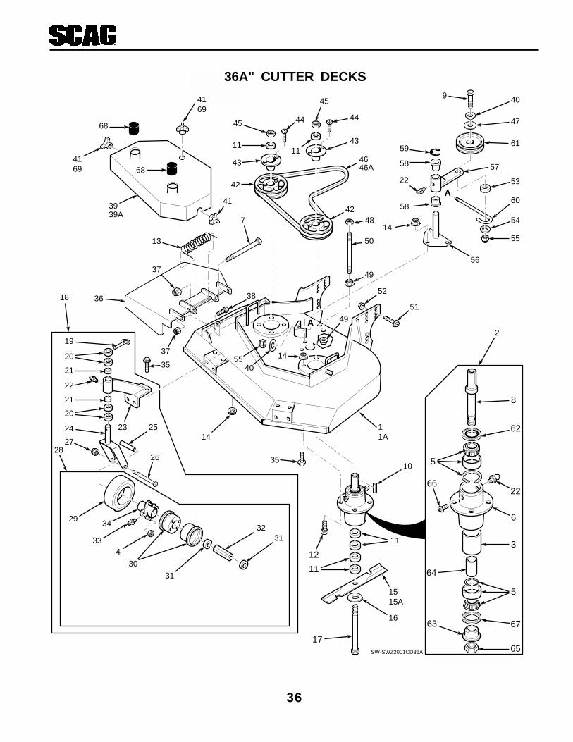
36
36A" CUTTER DECKS
19
20
21
22
21
20
24 23
18
25
37
26
2728
29
30
31
334
34 3231
35
1411A
36 38
45
11
43
42
44
45
43
46
44
11 59
6058
9
48
2
14
58
22
42
50
52
51
49
4169
49
SW-SWZ2001CD36A
8
62
5
22
3
65
63
6
66
67
64
5
3941
4169
A
A
57
14
56
4055
35
11
10
17
16
1515A
12
11
13
37
7 54
55
53
61
47
40
46A
39A
68
68

37
Ref. PartNo. Number Description
1 461362 Cutter Deck (Includes Decals)1A 461412 Cutter Deck for SWZ36A-15KA (Includes Decals)2 46631 Cutter Spindle Assy.3 43312 Spacer, Outside4 48307-08 Tapered Nut, 5/16-245 481022 Tapered Bearing (Two)6 43294 Spindle Housing7 04001-108 Bolt, 5/16-18 x 4-1/4" Hex Head8 43589 Spindle Shaft9 04001-77 Bolt, 3/8-16 x 3-1/2" Hex Head10 04063-08 Key, 1/4 x 1/4 x 2"11 43278 Spacer, Cutter Blade - Small12 04001-10 Bolt,5/16-18 x 1-1/4" Hex Head13 482245 Spring, Chutte Return14 04019-03 Nut 5/16-18 Serrated Flange15 482462 Cutter Blade, 18"15A 482467 Cutter Blade, 18 Hi Lift16 04040-10 Flatwasher, 5/8 W17 04001-41 Hex Hd. Bolt, 5/8-11 x 9-1/2"18 46079 Caster Assembly (Inc.19-28)19 04066-01 Quick Pin20 43037-01 Spacer, Caster Yoke, 1/2" long21 48100-01 Bronze Bearing22 48114-04 Grease Fitting23 46082 Support Assembly (Inc. 21-23)24 45006 Caster Yoke25 43022 Sleeve, Caster Wheel Bearing26 04001-37 Hex Hd. Bolt, 1/2-13 x 5-1/2"27 04021-07 Elastic Stop Nut, 1/2-1328 48307 Wheel Assy. (Inc.4, 29-34)29 481774 Tire only, Caster WheelNS 481773 Inner Tube only30 481772 Rim Pair, Caster Wheel31 481770 Retainer, Bearing, Caster Wheel32 481769 Roller Bearing, Caster Wheel33 48114-03 Grease Fitting, 45 degree 1/4-2834 481768 Hub Assembly35 04017-16 Cpscrw,5/16-18 x 3/4" Ser.Flg. Hex Head36 461295 Discharge Chute37 04021-10 Hex Nut, 5/16-18 Elastic Stop38 04001-09 Hex Hd Bolt, 5/16-18 x 1"39 46797 Belt Cover Assy (Includes Decal)39A 461413 Belt Cover Assembly w/decals (SWZ36A-15KA)40 04041-07 Flat Washer, 3/8" Special41 04029-03 Wing Nut, 3/8-1642 48924 Pulley
36A" CUTTER DECKS
Ref. PartNo. Number Description
43 48926 Tapered Hub44 04001-01 Hex Hd. Bolt, 1/4-20 x 3/4"45 04020-09 Hex Nut, 5/8-1146 48204 Belt, Blade Drive47 43077 Spacer48 04021-05 Hex Nut, 3/8-16 Center Locknut49 04019-04 Nut, 3/8-16 Serrated Flange50 04004-02 Support, Belt Cover51 04017-42 Cpscrw, 7/16-14 x 1"Ser.Flg. HH52 04019-05 Nut, 7/16-14 Serrated Flange53 43277 Spacer, J-Hook54 04041-12 Washer, 3/8 x 1-1/2 x 16 GA55 04021-09 Elastic Stop Nut, 3/8-1656 45423 Idler Pivot57 46748 Idler Arm Assy. (Inc. 22 & 58)58 48100-02 Bronze Bearing59 04050-05 Retaining Ring, 1-1/8" Ext. ”E”60 44078 J-Hook61 482416 Idler Pulley, Belt Clutch62 481024 Seal, Cutter Spindle63 43297 Spindle Bushing64 43296 Spacer, Inside65 481035 Nut, 1-1/16 - 18 Thread66 48677 Relief Fitting, Cutter Spindle67 481025 Seal, Cutter Spindle68 48098 Spindle Shield69 04029-04 Wing Nut, 3/8-16 (Small) Top Side69 04029-04 Wing Nut, 3/8-16 (Small) RH Side
* Common hardware which should be purchased locally. All bolts are Grade 5 plated, all other fasteners zincplated.

38
48A, 52A, 61A, & 72" CUTTER DECKS
19
20
21
7
21
20
24 23
18
25
37
26
2728
29
30
31
3383
34 32
31
35
79
14
80
53
1
39
4149
52
50 55 54
45
11
43
4
4445
43
47
44
11
48
11
4445
43
42
46
51
64
65
9
6114
60
7
56, 56A61
59
51
62
40
74
63
76
67
7
77
78
77
57
68
64
51
4051
35
35
50
14
4163
40
58
2
SW-SWZ 2001CD48, 52"
8
66
5
7
70
72
71
6
69
81
3
5
11
10
16
1515A
12
11
17
36
82
37 13
38AA
A
4173
40
75
14
22
38

39
1 461367 Cutter Deck Adv. (Inc. decals) x*1 461372 Cutter Deck Adv. (Inc. decals) x*1 461458 Cutter Deck Adv. (Inc. Decals) x1 461460 Cutter Deck Adv. (Includes decals) x1 461142 Cutter Deck (Includes decals) x2 46631 Spindle Assembly x x x x3 43296 Spacer, Inside x x x x4 48924 Pulley x x x x5 481022 Tapered Bearing (Two) x x x x6 43294 Spindle Housing x x x x7 48114-04 Grease Fitting Str. 5/16 x x x x8 43589 Spindle Shaft, Tapered Brng x x x x9 45037 Idler Pivot x x x x10 04063-08 Key, 1/4 x 1/4 x 2" x x x x11 43592 Spacer, Cutter Blade - Small x x x x12 04001-10 Bolt, 5/16-18 x 1-1/4" Hex Head x x x x13 04001-108 Bolt, 5/16-18 x 4-1/4" Hex Head x x x x14 04019-03 Serrated Flange Nut, 5/16-18 x x x x15 482461 Cutter Blade 16-1/2" x15 482462 Cutter Blade 18" x15 482464 Cutter Blade 21" x15 482465 Cutter Blade 24" x15A 482466 Cutter Blade 16-1/2 Hi Lift x15A 482467 Cutter Blade 18 Hi Lift x15A 482469 Cutter Blade 21 Hi Lift x16 04040-10 Flatwasher,5/8" (.688 x 1.75 x .134)x x x x17 04001-41 Hex Head Bolt, 5/8-11 x 9-1/2" x x x x18 46079 Caster Assembly, (incl.19-28 & 7) x x x x19 04066-01 Quick Pin x x x x20 43037-01 Spacer, Caster Yoke, 1/2" thick x x x x21 48100-01 Bronze Bearing x x x x22 48098 Spindle Shield x x x x23 46082 Support Assembly, (incl. 21-23) x x x x24 45006 Caster Yoke x x x x25 43022 Sleeve, Caster Wheel Bearing x x x x26 04001-37 Hex Hd Bolt, 1/2-13 x 5-1/2" x x x x27 04021-07 Elastic Stop Nut, 1/2-13 x x x x28 48307 Wheel Assy. (incl. 29-34,81) x x x x29 481774 Tire only, Caster Wheel x x x xNS 481773 Inner Tube only, Caster Wheel x x x x30 481772 Rim Pair, Caster Wheel x x x x31 481770 Bearing Retainer, Caster Wheel x x x x32 481769 Roller Bearing, Caster Wheel x x x x33 48114-03 Grease Fitting 45 deg., 1/4-28 x x x x34 481768 Hub Assembly, (incl. bolts) x x x x35 04017-16 Capscrew, 5/16-18 x 3/4" x x x x36 461292 Discharge Chute x x36A 461295 Discharge Chute x x37 04021-04 Nut, 5/16-18 Elastic Elastic Stop x x x x38 04001-09 Bolt, 5/16-18 x 1" Hex Head x x x x39 46798 Belt Cover (Includes decals) x39 461095 Belt Cover (Includes decals) x39 46804 Belt Cover (Includes decals) x39 46805 Belt Cover (Includes decals) x39 46848 Belt Cover (Includes decals) x40 04041-07 Flat Washer, 3/8" Special x x x x41 04029-03 Wing Nut, 3/8-16 (Large) x x x x42 48924 Pulley x x42A 48753 Pulley x42B 48967 Pulley x
Ref. PartNo. No. Description 48 52 61 72
43 48926 Tapered Hub x x x x44 04001-01 Bolt, 1/4-20 x 3/4" Hex Head x x x x45 04020-09 Nut, 5/8-11 Hex x x x x46 48923 Pulley, Double x x46A 48940 Pulley, Double x46B 48966 Pulley, Double x47 48087 Belt, RH Blade Drive x47 48285 Belt, RH Blade Drive x47 48265 Belt, RH Blade Drive x47 48295 Belt, RH Blade Drive x48 48089 Belt, Blade Drive x48 48286 Belt, Blade Drive x48 48088 Belt, Blade Drive x48 48296 Belt, Blade Drive x49 04021-05 Nut, 3/8-16, Nut Centerlock x x x x50 04019-04 Nut, 3/8-16, Serrated Flange x x x x51 04021-09 Nut, 3/8-16 Elastic Stop x x x x52 04004-02 Support, Belt Cover x x x x53 04001-08 Bolt, 5/16-18 x 1/2" Hex Head x x x x54 04017-42 Cpscrw,7/16-14 x 1"Ser Flng H Hd x x x x55 04019-05 Nut, 7/16-14 Serrated Flange x x x x56 04041-08 Flat Washer 3/4" Special x x x x56A 04041-08S Flat Washer 3/4" Special x x x x57 44078 J-Hook x x x x58 48181 Idler Pulley, “V” Groove x x x x59 04050-02 Retaining Ring, 3/4" Ext.”E” x x x x60 46081 Idler Arm Assy. (Incl. 7 & 61) x x x x61 48100-05 Bronze Bearing x x x x62 43028 J-Rod, Idler Pulley x x x62A 44078 J-Rod, Idler Pulley x63 43077 Spacer, J-Rod x x x x64 04041-12 Washer, 3/8 x 1-1/2 x 16 ga. x x x x65 04001-46 Bolt, 3/8-16 x 2-1/4" Hex Head x x x x66 481024 Seal, Cutter Spindle x x x x67 46748 Idler Arm Assy (Includes 22&77) x x x x68 43277 Spacer, J-Rod x x x x69 48677 Relief Fitting, Cutter Spindle x x x x70 43312 Spacer, Outside, Cutter Spindle x x x x71 43297 Spindle Bushing x x x x72 481035 Nut, Cutter Spindle x x x x73 04029-04 Wing Nut, 3/8-16 (Small) Top Side x x x x74 04001-77 Bolt, 3/8-16 x 3-1/2" Hex Head x x x x75 45329 Idler Pivot x x x x76 482416 Idler Pulley, Belt Clutch x x x x77 48100-02 Bronze Bearing x x x x78 04050-05 Retaining Ring x x x x79 48038 Guide Roller x x x x80 45944 Roller Shaft x x x x81 481025 Seal, Cutter Spindle x x x x82 482245 Spring, Chute Return x x x x83 48307-08 Nut, 3/8-24 Tapered x x x x
48A, 52A, 61A, & 72" CUTTER DECKSRef. PartNo. No. Description 48 52 61 72
* Measure the engine deck to determine frame size. 461372 is for small frame (16") & 461374 is for large frame (20")

40
ENGINE DECK
50
51
1
58
48
4
3
2
1816
16
17
33
9
1110
1212A
1311
11A
14
8
7
7
60
63
61
6
15
20
21
1922
2364
38
24
27
26
254345
45
41
46
4443
40
35
39
38
3434A
38
4747A
4939
38
55
030441698
56
57
6543
RED BLK
ELECTRICSTART ONLY
4542
32
5935
37
54
45
5
62
31
30
28
29
43
53

41
Ref. PartNo. No. Description 14KA 15KA 17KA 21KAE
1 48842 Engine 14KA Kawasaki x1 482144 Engine 15KA Kawasaki x1 481563 Engine 17KA Kawasaki x1 48971 Engine 21KAE Kawasaki x2 04050-10 Retaining Ring, 1/2" Ext. "E" x x x x3 04020-02 Hex Nut, 1/4-20 x x x x4 04010-10 Screw, 1/4-20 x 2" Rnd. Hd. Phil. x x x x5 421239 Strap, Fuel Tank x x x x6 481603 Cap, Fuel Tank x x x x7 48292 Pad, Rubber-Fuel Tank - Upper x x x x8 46846 Fuel Tank Assy. (incl. 9, 10) x x x x9 48309 Bushing x x x x10 48308 Valve, Fuel Shut-off x x x x11 48059-01 Clamp, Fuel Hose x11A 48059-02 Clamp, Fuel Hose, (KA Only) x x12 48058 Fuel Hose, 1/4 ID x 20" KA x x12A 48058 Fuel Hose, 1/4 ID x 23" x13 48028-05 Cable Tie x x x14 48057-02 Fuel Filter x15 48179 Fuel Hose, 7/32 ID x 3-1/2" x16 04015-06 Capscrew, #10-32 x 1 Soc. Hd. x x x17 46323 Lever Assy., Pump Control -LH x x x x18 46324 Lever Assy., Pump Control -RH x x x x19 48015 Battery x20 04001-44 Bolt, 1/4-20 x .50" x21 04020-02 Nut, 1/4-20 x22 48099 Pad x23 42392 Battery Cover x24 04029-01 Wing Nut, 1/4-20 x25 423356 Battery Support x26 48661 Pad, Rubber x27 04003-01 Bolt, 1/4-20 x 6" Carriage x28 04003-28 Carriage Bolt, 5/16-18 x 2" x x29 04003-04 Carriage Bolt, 5/16-18 x 1" x x30 422553 Stiffener x x31 422552 Plate, Backing x x32 04021-08 Nut, 1/4-20 Elastic Stop x x x x33 48205 Pad, Rubber-Fuel Tank, Lower x x x x34 461358 Engine Deck, 16" Wide, w/decals x x x34A 461359 Engine Deck, 20" Wide, w/decals x x35 04003-09 Bolt,1/4-20 x 1-1/4" Hex Head x x x x36 04019-02 Nut, 1/4-20 Serrated Flange x x37 04017-18 Capscr., 5/16-18 x 1.25 Sr. Flg. x x x x38 04019-03 Nut, 5/16-18 Serr. Flange x x x x39 04019-04 Nut, 3/8-16 Serr. Flange x x x x40 04001-22 Bolt, 3/8-16 x 2-3/4" Hex Head x x x x
41 04001-08 Hex Head Bolt, 5/16-18 x .75" x x x x42 04040-14 Flat Washer 1/4" x x x x43 04021-10 Nut, 5/16-18 Elastic Stop x x x x44 04003-04 Carrage Bolt, 5/16-18 x 1" x x x x45 48030-09 Clamp x x x x46 421370 Clutch Bracket x x x x47 04017-19 Capscr, 5/16-18 x 1.50" Sr. Flg. x47A 04002-01 Metric HH Bolt, M8-1.25 x M30 x x x48 04031-09 Lock Washer, 5/16 Int. Tooth x x x x49 04030-03 Lock Washer, 5/16 x x50 48257 Pipe Cap x51 48402-04 Pipe, 4.75" Nipple x52 04003-09 Carrage Bolt, 1/4-20 x 1-1/4" x x53 481717 Wire Hrns. Adapter, 17KA x54 45418 Pulley Guard, 16" Frame x x54 45419 Pulley Guard, 20" Frame x x55 45283 Shaft Weldment, RH Pump Cntl. x x x x56 422930 Bracket, Capacitor x x57 21013-2064 Condenser (order from Kaw.) x58 04002-07 Metric H H Bolt, 8-1.25 x 10 x x x59 21066-2071 Regulator, (order from Kaw.) x60 48029-02 Battery Cable, 31.5" Red x61 48029-14 Battery Cable, 31.5 Black x62 423308 Battery Box x63 48126 Rubber Boot x64 04003-12 Carrage Bolt, 5/16-18 x .75 x65 48030-10 Cable Clamp, .75 ID x x x
ENGINE DECK
Ref. PartNo. No. Description 14KA 15KA 17KA 21KAE

42
DRIVE AND BRAKE COMPONENTS
17
12
13
15
14
16
2223
50
48
47
50
48
11
2424A
45
25
34 36
37 41
1
39
38
40
42
51
42
2
2
49
5
46
47
53
4344
35
SWZ01D&BC
3, 3A
1
2
4
7
98
449
A A
10, 10A
52
7
11
6
2021
1819
26
27
28A28B28C
33
31
32
2930
A
A
54 55
56
57
58
59
6056
56

43
29 422534 Plate, Backing x x x x30 48030-09 Clamp x x x x31 04021-10 Nut, 5/16-18 Elastic Stop x x x x32 481716 Rubber Pad, Clutch Stop x x x x33 422533 Retainer, Clutch Stop x x x x34 04001-12 Hex Head Bolt, 5/16-18 x 1.75" x x x x35 481665 Pulley, Pump Drive Engine x x x x36 04001-13 Hex Head Bolt, 5/16-18 x 2.75" x x x x37 04021-05 Nut, 3/8-16 Center Lock x x x x38 48224 Ball Bearings x x x x39 451109 Idler Arm Weldment, Pump x x x x40 48224 Ball Bearings x x x x41 481835 Spring, Pump Belt Idler x x x x42 04019-03 Nut, 5/16-18 Serr. Flange x x x x43 04063-24 Key, 1/4x1/4x2.75" Clutch Mtg. x x x x44 04063-01 Key, 1/4x1/4x1.25" Pulley Mtg. x x x x45 04041-07 Flat Washer, 3/8 x x x x46 48473 Pulley, Idler 4.5" x x x x47 48586 Pulley, Pump Shaft x x x x48 04012-04 Setscrew, 5/16-18 x 3/8" x x x x49 04030-04 Lockwasher, 3/8 x x x x50 04063-14 Key, 5.0 x 5.0 x 25mm x x x x51 43504 Pivot, Idler (Long) x x x x52 43032 Swivel Joint x x x x53 422713 Base, Idler Pivot x x x x54 04001-54 Bolt, Hex Head 3/8-16 x 3" x x x x55 04001-22 Bolt, Hex Head 3/8-16 x 2.75" x x x x56 04043-04 Flatwasher 3/8" x x x x57 481873 Chain x x x x58 04001-59 Bolt, Hex Head 1/4-20 x 1.25" x x x x59 04021-09 Nut, Hex Elastic Stop 3/8-16 x x x x60 04019-02 Nut, Serrated Flange 1/4-20 x x x x
Ref. PartNo. No. Description 14KA 15KA 17KA 21KAE
DRIVE AND BRAKE COMPONENTS
Ref. PartNo. No. Description 14KA 15KA 17KA 21KAE
1 481876 Ring, Split x x x x2 04001-19 Bolt, 3/8-16 x 1" Hex Head x x x x3 45842 Brake Shaft Assy. Wlmt.Small x x x3A 45854 Brake Shaft Assy. Wlmt.Large x x4 04062-01 Hair Pin Cotter, .094 x 1.62 x x x x5 04003-12 Carrage Bolt, 5/16-18 x .75" x x x x6 44126 Rod, Brake Lower x x x x7 04019-04 Nut, 3/8-16 Serr. Flange x x x x8 43415 Bushing, Brake x x x x9 48114-05 Grease Fitting x x x x10 45860 Brake Actuator Wlmt., LH x x x x10A 45861 Brake Actuator Wlmt., RH x x x x11 04001-46 Bolt, 3/8-16 x 2-1/4" x x x x12 481618 Tire, 16 x 6.50, 4 ply x x x x13 48004-04 Rim Assy x x x x14 422214 Lock Washer, Wheel Motor x x x x15 48679 Hex Castle Nut, 3/4-28 UNEF x x x x16 04028-01 Nut, Lug x x x x17 481502 Wheel Assy., (incl. 31,32) x x x x18 422215 Brake Drum x x x x19 04008-01 1/2-20 Serrated Bolt x x x x20 46928 Hub, Wheel x x x x21 481470 Brake Band, 7.5" x x x x22 04063-07 Key, 3/16 X .75 Woodruff x x x x23 481416 Wheel Motor x x x x24 48553 Belt, Pump Drive (Sm Frame) x x x24A 48587 Belt, Pump Drive (Lg Frame) x x25 461397 Electric Clutch x x x x26 04041-28 Flat Washer .469 x 1.75 x .25 x x x x27 04030-05 Lock Washer, 7/16 x x x x28A 04103-05 Hex Head Bolt, M10-1.5 x 65 x x28B 04102-02 Hex Head Bolt, 7/16-20 x 2.00" x x

44
HANDLE ASSEMBLY
87
45
15
16
16
15
8
2
76
5
34
1
22
20
2324
26
30
34
3432
3
37
36
61
39
67
38
37
35
40
37
38
3
11
29
27
11
68
9
2119
17
14
13
11
18
19
28
16
24
25
31
10
42
12
40
390S0190B
75
76
74
71
40
60
60
102
8092
91
85
88
61
82
86
A
A
7993
66
69
94
78
79
B
B
101
99
65
98
73
95
58
63
48
61
92
88
37
66
52
97
53
100
64
849610
57
41
8266
6
73
61
60
5950
51
46
43
70
62
45 114445
42
4749
11
24
72
C
3
C33
54
77
78
58
65

45
1 461128 Upper Handle Wlmt. W/Decals x x1 461129 Upper Handle Wlmt. W/Decals x2 42675 Quadrant, Speed Control x x x3 04062-02 Hairpin, .094 x 1.19 x x x4 45282 Lever, Speed Adjustment x x x5 43086 Bushing, Speed Adjustment Lever x x x6 04001-20 Hex Head Bolt, 3/8-16 x 1.5" x x x7 48493-01 Ball Plunger x x x8 48092 Knob, Speed Adjustment x x x9 04014-01 Capscrew, 1/4-20 x 3/4" FHHS x x x10 04021-08 Nut, 1/4-20 Elastic Stop x x x11 04021-10 Nut, 5/16-18 Elastic Stop x x x12 04010-01 Screw, #10-32 x 1/2" PW HD x x x13 48946 Throttle Control x x x14 04019-01 Nut, #10-32 Serr. Flange x x x15 48312 Bushing x x x16 45572 Handle, Oper. Presence-RH x x x
45573 Handle, Oper. Presence-LH x x x17 481687 Switch,Elec.Clutch Eng. (incl.Nut) x x x18 481865 Wire Harness, Manual Start x x
482026 Wire Harness, Electric Start x19 48609 Key Switch, Manual Srt. (inc. Hdw) x x
48798 Key Switch, Electric Srt. (inc. Hdw) x20 461242 Neutral Latch-RH x x x
461241 Neutral Latch-LH x x x21 48717 Switch, Neutral Interlock x x x22 48159 Grip x x x23 04032-01 Washer, Curved Spring x x x24 04040-15 Flat Washer x x x25 04021-10 Nut, 5/16-18 Elastic Stop x x x26 04001-17 Hex Head Bolt, 5/16-18 x 2" x x x27 04001-53 Hex Hd. Bolt, 5/16-18 x 2.5" x x x28 46089 Lever, Steering Control (incl. 29) x x x29 48144 Grip, Steering Control x x x30 44134 Rod, Steering Control x x x31 48951 Spring, Handle Return x x x32 04017-27 Capscr., 3/8-16 x 1" Ser. Flange x x x33 481866 Spring x x x34 04019-04 Nut, 3/8-16 Serr. Flange x x x35 44051 Rod Speed Control x x x36 451107 Bellcrank, Speed Control x x x37 04012-02 Setscrew, 1/4-28 x .25" x x x38 46335 Cam, Speed Control (incl. SS) x x x39 43166 Jackshaft, Speed Control x x x40 04063-13 Key, 1/8 x 1/2" Woodruff x x x41 04060-06 Roll Pin, 3/16-.75 x x x42 04021-10 Nut, Elastic Stop 3/8-16 x x x43 48223 Flange, Bearing x x x44 * Capscrew, 5/16-18 x 1" Serr. Flg. x x x45 04019-03 Nut, 5/16-18 Serrated Flange x x x46 422795 Plate, Side x x x47 43536 Support, Neutral Support x x x48 48409 Bearing, Speed Ctrl. Bellcrank x x x49 04001-69 Hex Head Bolt, 5/16-18 x 1-3/4" x x x50 48494-02 Spring, Return x x x
HANDLE ASSEMBLY
Ref. PartNo. No. Description 15KA 17KA 21KAE
Ref. PartNo. No. Description 15KA 17KA 21KAE
51 43522 Spacer, Side Plate x x x52 04041-08S Flat Wshr., 3/4-.766 x 1.25 x .035 x x x53 04063-07 Key, Woodruff, 3/16 x .75" x x x54 04001-59 Bolt, Hex Head, 1/4-20 x 1.25 x x x55 04001-08 HH Bolt,5/16-18 x .75" x x x56 04030-03 Lock Washer, 5/16 x x x57 04050-02 Clip, Retaining .750 diameter x x x58 48224 Bearing, Ball Neutral Return x x x59 46747 Cam, Neutral (incl. grease ftng.) x x x60 48114-05 Grease Fitting, 1/4-28 UNF x x x61 04050-01 Retaining Ring, 5/8 Ext. "E" x x x62 04001-09 Hex Head Bolt, 5/16-18 x 1" x x x63 482146 Lever, Speed Control x x x64 04001-01 Bolt, Serr. Flange 1/4-20 x.75" x x x65 482431 Linkage Assembly x x x66 04041-07 Flat Wshr., 15/16 x .3906 x 12 ga x x x67 461358 Deck, Engine 16" Wide x x
461359 Deck, Engine 20" Wide x x68 04001-10 Hex Head Bolt, 5/16-18 x 1.25" x x x69 482314 Choke Control x x x70 04001-152 Bolt, Hex Head 3/8-16 x 4.25" x x x71 42413 Fuse Holder x x x72 43520 Swivel Joint, Steering Rod x x x73 48100-06 Bushing x x x74 48298 Blade Fuse, 20A x x x75 04021-01 Nut, #10-32 Elastic Stop x x x76 04010-03 Screw, #10-32 x 1.5" Phillips x x x77 04030-02 Lockwasher, 1/4" x x x78 43032 Swivel Joint x x x79 44125 Rod, Brake Lever x x x80 04001-21 Hex Hd. Bolt, 3/8-16 x 1.75" x x x81 04015-13 Soc. Hd. Capscrew, #8-32 x .5" x x x82 04021-09 Nut, 3/8-16 Elastic Stop x x x83 04041-23 Washer #8-.170 x .375 x .032 x x x84 04001-01 Bolt, 1/4-20 x .75" x x x85 43212 Spacer x x x86 46954 Parking Brake Lever with Grip x x x87 481476 Switch, Safety x x x88 04020-14 Nut, 3/8-24 x x x89 481411 Bushing, Bearing Retainer x x x90 481420 Bearing, Neutral Lock x x x91 48342 Grip, Parking Brake x x x92 421203 Plate, Threaded x x x93 04062-01 Hairpin, .094 x 1.62" x x x94 421622 Bracket, Choke Mtg. x x x95 44126 Rod, Lower Brake x x x96 422273 Plate, Coupler x x x97 451113 Shaft, Pump Control x x x98 481879 Spring x x x99 481885-03 Knob, Tracking Adjustment x x x100 48829 Block, Pump Control x x x101 49236 Control, LH (inc. bush. & decal) x x x
49237 Control, RH (inc. bush. & decal) x x x102 481474 Switch, Parking Brake x x x
* Common hardware which should be purchased locally. All bolts are Grade 5 plated, all other fasteners zinc plated.

46
HYDRAULIC ASSEMBLY
B
ED
D A
E
C
C
F G
JH
HJ
1
2
3
5
6
78
9
3428
2810
10
33
11
12
1129
13
35
20
4
35
35
31
22
12
3
5
13
2018
6
B
5
34
33
16
7
8
2928
28
2323
A4
35
22
15
14
25
11
11
2323
1919
1010
1919
21
27
26
2002SWZU-HA
G
F
17
33
34
24
11
11
11
32
35
35
35
35
35 35
11
7 7

47
1 481164 Cap, Oil Reservoir2 461428 Oil Reservoir (With Fittings)3 482266-01 Elbow, 9/16 O-Ring x 3/8 Hose4 48811 Hose, 3/8" ID - 16" Long (Order By The Inch)5 48811 Hose, 3/8" ID - 7" Long (Order By The Inch)6 48350-04 Elbow, 90 deg. 7/16-20 JIC to 9/16-18 "O" Ring7 48603-06 O-Ring8 48551 Pump, Hydro-Gear BDP-10L1179 04003-11 Bolt, Carriage, 3/8-16 x 1.25"10 481265 Hose, Pump to Wheel Motor11 48603-02 O-Ring12 482266-03 Elbow, 7/16 O-Ring x 3/8 Hose13 48811 Hose, 3/8" ID - 10-1/4" Long (Order By The Inch)14 482417 Oil Filter Base15 482477 Tee, 3/8 O-Ring x JIC x 1/2 Hose16 422794 Strap, Hydraulic Tank17 422793 Bracket, Hydraulic Tank18 04017-16 Capscrew, 5/16-18 x .75" Serr. Flange19 48603-04 O-Ring20 482266-01 Elbow, 9/16 O-Ring x 3/8 Hose21 04019-03 Nut, 5/16-18 Serr. Flange22 482305 Hose, Formed 1/2" ID23 481849 Hose, Pump to Wheel Motor24 481507 Tube, Filler Neck25 461358 Engine Deck (16" Wide) W/Decals - Small Frame
461359 Engine Deck (20" Wide) W/Decals - Large Frame26 04019-04 Nut, 3/8-16 Serr. Flange27 48758 Oil Filter28 48485-01 Elbow, 45 Deg.-3/4-16 JIC Male x Male 3/4-16 O-Ring29 48603-03 O-Ring30 481537-02 Coupling, 3/8 Pipe to 1/2 Push-on31 482202 Elbow, 3/4-16 O-Ring x 1/2 Hose32 48571-02 Cap, 3/4-1633 04010-10 Screw, 1/4-20 x 2.0" Round Head Phillips34 04021-08 Nut, 1/4-2035 48136-05 Clamp, .87 max dia.
HYDRAULIC ASSEMBLY
Ref. PartNo. Number Description
* Common hardware which should be purchased locally. All bolts are Grade 5 plated, all other fasteners zinc plated.

48
HYDRAULIC PUMP ASSEMBLY
SC165G
11
49
11
12
10
68
13
7
18
5
14
15
16
17
19 20 21
22 1
23
24
25
26
28
27
3
2
Overhaul Seal Kit30
29
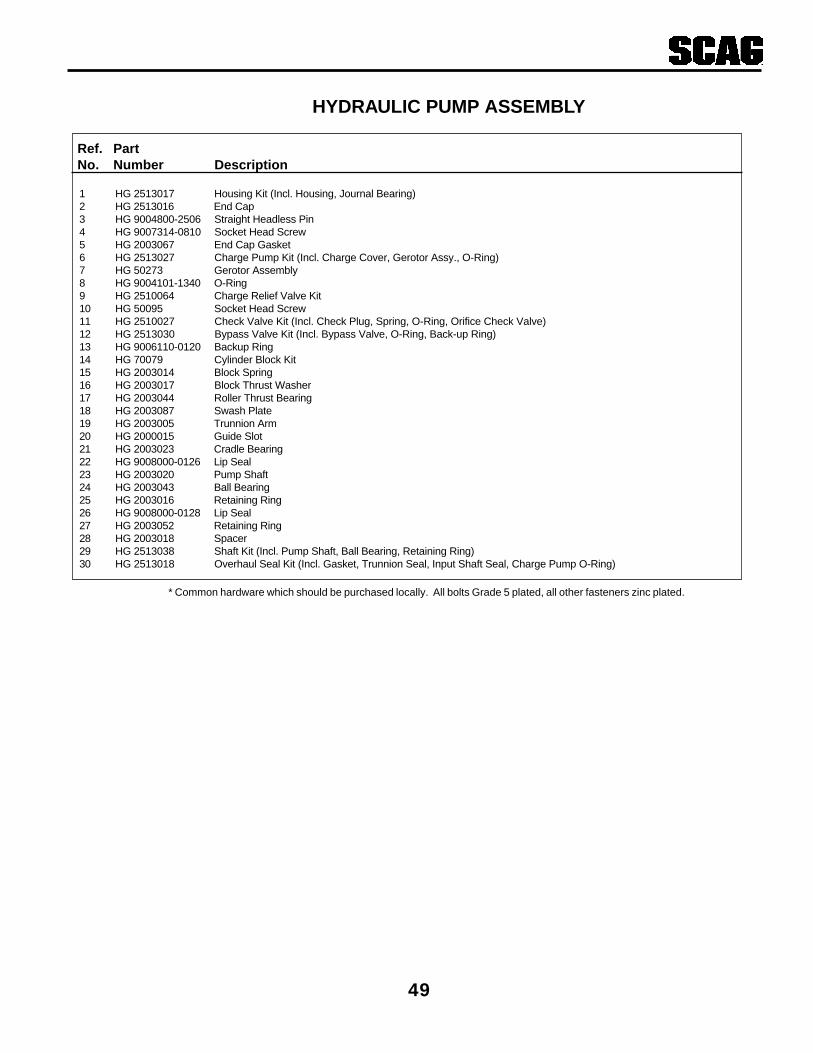
49
Ref. PartNo. Number Description
HYDRAULIC PUMP ASSEMBLY
1 HG 2513017 Housing Kit (Incl. Housing, Journal Bearing)2 HG 2513016 End Cap3 HG 9004800-2506 Straight Headless Pin4 HG 9007314-0810 Socket Head Screw5 HG 2003067 End Cap Gasket6 HG 2513027 Charge Pump Kit (Incl. Charge Cover, Gerotor Assy., O-Ring)7 HG 50273 Gerotor Assembly8 HG 9004101-1340 O-Ring9 HG 2510064 Charge Relief Valve Kit10 HG 50095 Socket Head Screw11 HG 2510027 Check Valve Kit (Incl. Check Plug, Spring, O-Ring, Orifice Check Valve)12 HG 2513030 Bypass Valve Kit (Incl. Bypass Valve, O-Ring, Back-up Ring)13 HG 9006110-0120 Backup Ring14 HG 70079 Cylinder Block Kit15 HG 2003014 Block Spring16 HG 2003017 Block Thrust Washer17 HG 2003044 Roller Thrust Bearing18 HG 2003087 Swash Plate19 HG 2003005 Trunnion Arm20 HG 2000015 Guide Slot21 HG 2003023 Cradle Bearing22 HG 9008000-0126 Lip Seal23 HG 2003020 Pump Shaft24 HG 2003043 Ball Bearing25 HG 2003016 Retaining Ring26 HG 9008000-0128 Lip Seal27 HG 2003052 Retaining Ring28 HG 2003018 Spacer29 HG 2513038 Shaft Kit (Incl. Pump Shaft, Ball Bearing, Retaining Ring)30 HG 2513018 Overhaul Seal Kit (Incl. Gasket, Trunnion Seal, Input Shaft Seal, Charge Pump O-Ring)
* Common hardware which should be purchased locally. All bolts Grade 5 plated, all other fasteners zinc plated.

50
WIRE HARNESSADAPTER - ENGINE
NEUTRAL INTERLOCK
BLADECLUTCH
E A
F B
G C
H D
INSTRUMENTPANEL HARNESS
GROUND
BL
AC
K W
/RE
D S
TR
IPE
BLACK
BLUE
WHITEWHITE
YELLOW
SWZ01SC421G
BLACK
ENGINE DECKWIRE HARNESS -
KOHLER,(SINGLE CYLINDER)
& 15HP, 17 HP KawasakiPART NO. 481073
REGULATORENGINE
NEUTRAL INTERLOCK
BLADECLUTCH
E A
F B
G C
H D
INSTRUMENTPANEL HARNESS
GROUND
BLACK W/RED STRIPE
BLACK
BLUE
WHITEWHITE
YELLOW
RE
DR
ED
BLACK
BL
AC
K
SWZ99SC417G
ENGINE DECK WIRE HARNESS -KAWASAKI
PART NO. 481074

51
HANDLE WIRE HARNESS -MANUAL STARTPART NO. 481865
SWZ2002-481680
HANDLE WIRING HARNESSKAWASAKI ELECTRIC START PART NUMBER:482026

52
ENGINE DECKWIRING HARNESSKAWASAKI ELECTRIC STARTPART NUMBER: 482008

53
REPLACEMENT DECALS & INFORMATION
48314481971
482285
481109
48656
482286
481414
482284 48404
481039
CHOKE
FAST
SLOW
PARKINGBRAKE
OFF
ON
48404
WARNINGINSTALL BELT COVER BEFORE
OPERATING MACHINEREAD OPERATOR'S MANUAL 481039
WARNINGFALLING HAZARD
USE ONLY SCAG APPROVEDRIDING ATTACHMENTS
SEE OPERATOR'S MANUAL 481109
MOUNT RIDINGATTACHMENT
HERE

54
REPLACEMENT DECALS & INFORMATION
481423
481438
FAST
SLOW
PARKINGBRAKE
OFF
ON
FAST
SLOW
PARKINGBRAKE
OFF
ON
36" - 48229748" - 48195352" - 48195461" - 481955

55
481878
481942
SPEEDCONTROL
SLOW
FAST
NEUTRALN
481124
481425
481124
OIL481425
SEEOPERATOR'S
MANUAL

NOTES

Any part of the Scag commercial mower manufactured by Scag Power Equipment and found, in the reasonable judgmentof Scag, to be defective in materials or workmanship, will be repaired or replaced by an Authorized Scag Service Dealerwithout charge for parts and labor. This warranty is limited to the original purchaser and is not transferable. Proof ofpurchase will be required by the dealer to substantiate any warranty claims. All warranty work must be performed by anAuthorized Scag Service Dealer.
This warranty is limited to the following specified periods from the date of the original retail purchase for defects inmaterials or workmanship:
* Wear items including drive belts, blades, hydraulic hoses and tires are warranted for ninety (90) days.* Batteries are covered for ninety (90) days.* Frame and structural components including oil reservoir, fittings, and oil coolers are warranted for 1 year.* Cutter decks are warranted against cracking for a period of three (3) years. (Parts and labor 1st year; Parts only 2nd and 3rd year) The repair or replacement of the cutter deck will be at the option of Scag Power Equipment. We reserve the right to request components for evaluation. This warranty does not cover any mower that has been subject to misuse, neglect, negligence, or accident, or that has been operated in any way contrary to the operating instructions as specified in the Operator’s Manual.* Engines and electric starters are covered by the engine manufacturer’s warranty period.* Major drive system components (hydraulic pumps and hydraulic motors only) are warranted for two (2) years by Scag Power Equipment. (Parts and labor 1st year; Parts only 2nd year) (Two year warranty excludes fittings, hoses, cooling system, oil reservoir, drive belts, transaxles). The repair or replacement of the hydraulic pump or hydraulic motor will be at the option of Scag Power Equipment. This warranty does not cover any mower that has been subject to misuse, neglect, negligence, or accident, or that has been operated in any way contrary to the operating instructions as specified in the Operator’s Manual.* Electric clutches have a Limited Warranty for 2 year (Parts and labor 1st year; Parts only 2nd year).* Cutter Spindle Assemblies 46631 have a Limited Warranty for three years (Parts and labor 1st year; Parts only 2nd and 3rd year).* Any Scag product used for rental purposes is covered by a 90 day warranty.
The Scag mower, including any defective part must be returned to an Authorized Scag Service Dealer within the warrantyperiod. The expense of delivering the mower to the dealer for warranty work and the expense of returning it to the ownerafter repair will be paid for by the owner. Scag’s responsibility is limited to making the required repairs and no claim ofbreach of warranty shall be cause for cancellation or rescission of the contract of sale of any Scag mower.
This warranty does not cover any mower that has been subject to misuse, neglect, negligence, or accident, or that hasbeen operated in any way contrary to the operating instructions as specified in the Operator’s Manual. The warrantydoes not apply to any damage to the mower that is the result of improper maintenance, or to any mower or parts that havenot been assembled or installed as specified in the Operator’s Manual and Assembly Manual. The warranty does notcover any mower that has been altered or modified, changing performance or durability. In addition, the warranty does notextend to repairs made necessary by normal wear, or by the use of parts or accessories which, in the reasonable judgmentof Scag, are either incompatible with the Scag mower or adversely affect its operation, performance or durability.
Scag Power Equipment reserves the right to change or improve the design of any mower without assuming any obliga-tion to modify any mower previously manufactured. All other implied warranties are limited in duration to the one (1) yearwarranty period or ninety (90) days for mowers used for rental purpose. Accordingly, any such implied warrantiesincluding merchantability, fitness for a particular purpose, or otherwise, are disclaimed in their entirety after the expirationof the appropriate one year or ninety day warranty period. Scag’s obligation under this warranty is strictly and exclusivelylimited to the repair or replacement of defective parts and Scag does not assume or authorize anyone to assume for themany other obligation. Some states do not allow limitations on how long an implied warranty lasts, so the above limitationmay not apply to you.
Scag assumes no responsibility for incidental, consequential or other damages including, but not limited to, expense forgasoline, expense of delivering the mower to an Authorized Scag Service Dealer and expense of returning it to the owner,mechanic’s travel time, telephone or telegram charges, rental of a like product during the time warranty repairs are beingperformed, travel, loss or damage to personal property, loss of revenue, loss of use of the mower, loss of time or inconve-nience. Some states do not allow the exclusion or limitation of incidental or consequential damages, so the above limita-tion or exclusion may not apply to you. This warranty gives you specific legal rights, and you may also have other rightswhich vary from state to state.
LIMITED WARRANTY - COMMERCIAL EQUIPMENT

Toda pieza del cortacésped comercial Scag fabricada por Scag Power Equipment que, según criterio razonable de Scag, presentemateriales o mano de obra defectuosos será reparada o reemplazada por un distribuidor autorizado Scag sin cargo por las piezas nimano de obra. Esta garantía se limita al comprador original y no es transferible. El distribuidor requerirá comprobante de compra parafundamentar cualquier reclamación de garantía. Todo trabajo bajo garantía debe realizarlo un distribuidor autorizado Scag.
Esta garantía se limita a los siguientes períodos especificados a partir de la fecha de compra original minorista con respecto a losmateriales o mano de obra defectuosos:
* Piezas de recambio, incluidas las correas de transmisión, cuchillas, conexiones hidráulicas y los neumáticos, están garantizadas pornoventa (90) días.
* Las baterías están cubiertas por noventa (90) días.* El chasis y los componentes estructurales, incluidos el cárter de aceite, las conexiones y los enfriadores de aceite, están garantizados
por un (1) año.* Las plataformas de corte están garantizadas contra grietas por un período de tres (3) años. (Piezas y mano de obra, primer año;
piezas solamente, segundo y tercer año) La reparación o el reemplazo de la plataforma de corte estarán sujetos a discreción de ScagPower Equipment. Nos reservamos el derecho de solicitar componentes para evaluación. Esta garantía no cubre ningún cortacéspedcon daños causados por uso indebido, imprudencia, negligencia o accidentes, o que se haya operado de manera contraria a laespecificada en el manual del operador.
* Los motores y arrancadores eléctricos están cubiertos durante el período de garantía que otorga el fabricante del motor.* Los componentes principales del sistema de transmisión (bombas hidráulicas y motores hidráulicos únicamente) están garantizados
por Scag Power Equipment por dos (2) años. (Piezas y mano de obra, primer año; piezas solamente, segundo año) (La garantía dedos años no incluye las conexiones, mangueras, el sistema de enfriamiento, cárter de aceite, las correas de transmisión, los ejestransversales). La reparación o el reemplazo de la bomba hidráulica o el motor hidráulico estarán sujetos a discreción de Scag PowerEquipment. Esta garantía no cubre ningún cortacésped con daños causados por uso indebido, imprudencia, negligencia o accidentes,o que se haya operado de manera contraria a la especificada en el manual del operador.
* Los embragues eléctricos tienen una Garantía limitada de 2 años (Piezas y mano de obra, primer año; piezas solamente, segundoaño).
* Los ensambles del eje de la plataforma de corte 46631 tienen una Garantía limitada de 3 años (Piezas y mano de obra, primer año;piezas solamente, segundo y tercer año).
* Cualquier producto Scag destinado a alquiler está cubierto por una garantía de 90 días.El cortacésped Scag, incluida cualquier pieza defectuosa, debe ser devuelto a un distribuidor autorizado Scag dentro del período
de garantía. El gasto de entrega del cortacésped al distribuidor para que realice el trabajo bajo garantía, así como el gasto de devolucióndel cortacésped al propietario después de la reparación, estarán a cargo del propietario. La responsabilidad de Scag se limita a larealización de las reparaciones requeridas y ninguna reclamación por incumplimiento de las obligaciones de garantía será causa decancelación o revocación del contrato de venta del cortacésped Scag.
Esta garantía no cubre ningún cortacésped con daños causados por uso indebido, imprudencia, negligencia oaccidentes, o que se haya operado de manera contraria a la especificada en el manual del operador. La garantía no será deaplicación en ningún caso de daño ocasionado al cortacésped como consecuencia de mantenimiento inadecuado o a cualquiercortacésped o piezas que no se hayan ensamblado o instalado de acuerdo con las especificaciones del manual del operador o el manualde montaje. La garantía no cubre ningún cortacésped que haya sufrido alteraciones o modificaciones que, como consecuencia, afecten sufuncionamiento o durabilidad. Asimismo, la garantía no se extiende a reparaciones necesarias por el desgaste normal o por el uso depiezas o accesorios que, según criterio razonable de Scag, sean incompatibles con el cortacésped Scag o afecten la operación,funcionamiento o durabilidad de éste.
Scag Power Equipment se reserva el derecho de cambiar o mejorar el diseño de cualquier cortacésped sin asumir porello obligación alguna de modificar cualquier cortacésped fabricado con anterioridad. Scag Power Equipment se reserva elderecho de cambiar o mejorar el diseño de cualquier cortacésped sin asumir por ello obligación alguna de modificar cualquier cortacéspedfabricado con anterioridad. Cualquier otra garantía implícita se limita a un período de garantía de un (1) año o noventa (90) días en elcaso de cortacéspedes destinados a alquiler. Por consiguiente, se rechaza en su totalidad cualquier garantía implícita, incluidas lasgarantías de comerciabilidad, adecuación para un fin determinado, o de otro tipo, después de la finalización del correspondiente períodode garantía de un año o noventa días. La obligación de Scag en virtud de la presente garantía se limita estricta y exclusivamente a lareparación o el reemplazo de piezas defectuosas, y Scag no asume ni autoriza a ningún otro a asumir en su lugar ninguna otra obligación.La limitación antes mencionada no será de aplicación en aquellos estados en los que no esté permitida la limitación del período devalidez de una garantía implícita.
Scag no asume responsabilidad alguna por daños incidentales, consecuentes ni cualquier otro, incluido, sin limitación, gasto degasolina, gasto de entrega del cortacésped a un distribuidor autorizado Scag y gasto de su devolución al propietario, tiempo de viajedel mecánico, cargos por comunicaciones telefónicas o telegramas, alquiler de un producto similar durante el período en que se llevana cabo las reparaciones bajo garantía, viajes, pérdida o daño de bienes personales, lucro cesante, daños ocasionados por la pérdida deluso del cortacésped, daños por la pérdida de tiempo o inconvenientes. La limitación o exclusión antes mencionada no será deaplicación en aquellos estados en los que no esté permitida la exclusión o limitación de daños incidentales o consecuentes. La
presente garantía le otorga derechos legales específicos, aparte de los derechos de los que usted goza, según el estado.
GARANTÍA LIMITADA - EQUIPO COMERCIAL

PART NO. 03100PRINTED 4/01
PRINTED IN USA
© 2001SCAG POWER EQUIPMENTDIVISION OF METALCRAFT OF MAYVILLE, INC.