model shup housing (panel mounting)/model mts mounting kit · model shup housing (panel mounting)...
TRANSCRIPT

GeneralSpecifications
<<Contents>> <<Index>>
GS 01B04F01-E
Model SHUP Housing (Panel Mounting)Model MTS Mounting Kit
Model SHUP HOUSING (Panel Mounting)The SHUP Housing Kit is for panel-mount instruments. Housings are available for standard-width panel-mount instruments as well as for double-width instruments such as the SRHD recorder. Instrument housings can be ordered separately from (prior to) the plug-in instrument modules themselves, and pre-wired.The MTS Mounting Kit (see below) can be ordered with the Housing Kit or separately.
STANDARD SPECIFICATIONS Housing: Open front. Connector for SPBD Portable
Manual Station.Wiring: Connectors are used to interconnect
instrument modules and housings.Signal Wiring to/from the Field: ISO M4 size (4 mm)
screws on terminal block.Power and Ground Wiring:100 V version: JIS C 8303 two-pin plug with earthing
contact. (IEC A5-15, UL498)220 V version: CEE 7 VII (CENELEC standard) plug.Cable Length: 300 mm.Material: Aluminium base plate, other parts steel.Mounting: Panel mounting (instruments can be
mounted side-by-side or separately). Rear of housing may be up to 75° below front.
Housing Dimensions: Standard: 182.5 (H) × 87 (W) × 480 (D) mm For SRHD; 182.5 (H) × 157 (W) × 480 (D) mmPanel cut-out: Standard: 172 ± 0.5 (H) × 80 ± 0.5 (W) mm For SRHD: 172 ± 0.5 (H) × 150 ± 0.5 (W) mmWeight: Standard: 2 kg (excluding mounting kit) For SRHD: 2.5 kg (excluding mounting kit)
OPTIONS/A2ER: For "220 V version" power supply./MTS: Supplied with kit for mounting instruments
Individually. When instruments are to be mounted side-by-side, order MTS Mounting Kit (see below) rather than /MTS option.
/SCF-GM: Mounting kit bezel color change from standard color (black). Chose the color from set of optional colors (see GS 22D1F1-E). Specify color code in space .
/FP: With blank panel. May be installed in spare housing where instrument
is not equipped.
MODEL AND SUFFIX CODESModel Suffix Codes Description
SHUP ........................................... Housing Kit-000 ...................................-200 ...................................
Standard versionDouble width for SRHD
Style Code *A ................................ Style A
Options
/A2ER/MTS/SCF-GM/FP
220V power supplyWith mounting kitBezel color changeWith blank panel
GS 01B04F01-E6th Edition: Sept. 2004 (KP)7th Edition: Jan. 2016 (YK)
Housing Kit
Mounting Kit

2
All Rights Reserved. Copyright © 2004, Yokogawa Electric Corporation
<<Contents>> <<Index>>
GS 01B04F01-E Jan.18. 2016-00
Model MTS MOUNTING KITThe MTS Mounting Kit comprises a bezel used with the SHUP Housing, plus a clamp to stop sideways movement of instruments in housings. When instruments are mounted individually, order one mounting kit per instrument. Otherwise, order one mounting kit per row of instruments.
STANDARD SPECIFICATIONSBezel: Aluminium die-cast material, black baked-
enamel finish.Weight: 0.4 kg.
Components of Mounting Kit
Item No. Part No. Name Quantity1 E9310CK Bezel (right) 12 E9310CL Bezel (left) 13 Y9406EB Screw 44 E9310CT Special screwdriver 15 E9310DT Clamp 2
OPTIONS/SCF-GM: Mounting kit bezel color change from
standard color (black). Chose the color from set of optional colors (see GS 22D1F1-E). Specify color code in space .
MODEL AND SUFFIX CODESModel Suffix Codes Description
MTS-000 ........................Mounting Kit for use with YEWSERIES 80 Housing Kit
Option /SCF-GM Bezel color change
F01.ai

3<<Contents>> <<Index>>
All Rights Reserved. Copyright © 2004, Yokogawa Electric Corporation GS 01B04F01-E Jan.18. 2016-00
EXTERNAL DIMENSIONS1) Standard
F02.ai
Unit: mm
87
22
70
3480
170
9.5
440
182.5
Panel Thickness 3.2 to 20
2-pole-plus-earth Plug
Power Socket
Wiring DuctSupporting Angle
2) For SRHD
F03.ai
157
223
480
140
170
9.5
440
182.5
Panel Thickness 3.2 to 20
2-pole-plus-earth Plug
Power SocketSee the belowdrawings.Wiring Duct
Supporting Angle
F04.ai
100 V Version Plug
JIS C 8303 15A 125 V Two-pin Plug with Earthing Contact
14.6 Max.
4.6±0.2
17±1
Earth Pole
1.5±0.156.3±0.3
11.9
3 Min
10.8
21.4 Max.
11.7±0.4
12.7 Min
F05.ai
CEE Publication 7 Standard Sheet VII10/16A 250 V Two-pole Plug with Dual-earthing Contacts
220 V Version Plug32.2
36.532.0 19.0
19.0
5.3
10.0
4.0
3.74.8
Earth Contacts Hole Earth Contacts
4
All Rights Reserved. Copyright © 2004, Yokogawa Electric Corporation
<<Contents>> <<Index>>
GS 01B04F01-E Jan.18. 2016-00
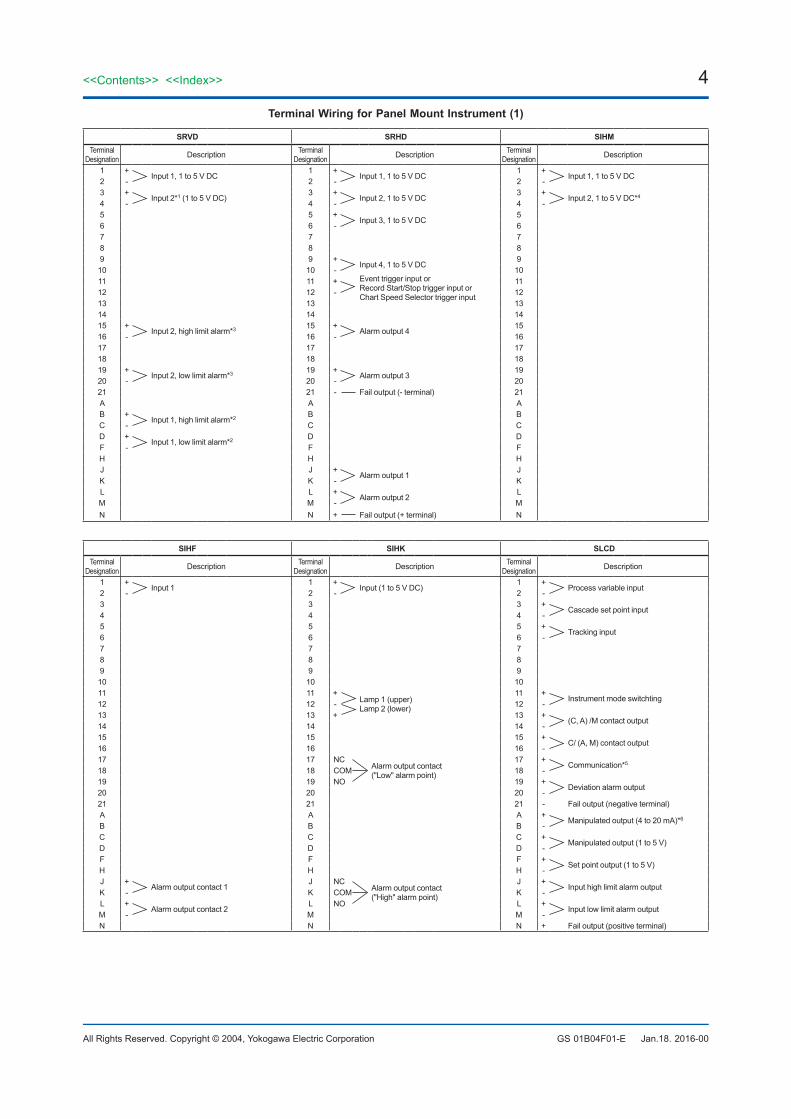
Terminal Wiring for Panel Mount Instrument (1)
SRVD SRHD SIHMTerminal
Designation Description Terminal Designation Description Terminal
Designation Description
1 +Input 1, 1 to 5 V DC
1 +Input 1, 1 to 5 V DC
1 +Input 1, 1 to 5 V DC
2 - 2 - 2 -3 +
Input 2*1 (1 to 5 V DC)3 +
Input 2, 1 to 5 V DC3 +
Input 2, 1 to 5 V DC*44 - 4 - 4 -5 5 +
Input 3, 1 to 5 V DC5
6 6 - 67 7 78 8 89 9 +
Input 4, 1 to 5 V DC9
10 10 - 1011 11 + Event trigger input or
Record Start/Stop trigger input orChart Speed Selector trigger input
1112 12 - 1213 13 1314 14 1415 +
Input 2, high limit alarm*3 15 +Alarm output 4
1516 - 16 - 1617 17 1718 18 1819 +
Input 2, low limit alarm*3 19 +Alarm output 3
1920 - 20 - 2021 21 - Fail output (- terminal) 21A A AB +
Input 1, high limit alarm*2 B BC - C CD +
Input 1, low limit alarm*2 D DF - F FH H HJ J +
Alarm output 1J
K K - KL L +
Alarm output 2L
M M - MN N + Fail output (+ terminal) N
SIHF SIHK SLCDTerminal
Designation Description Terminal Designation Description Terminal
Designation Description
1 +Input 1
1 +Input (1 to 5 V DC)
1 +Process variable input
2 - 2 - 2 -3 3 3 +
Cascade set point input4 4 4 -5 5 5 +
Tracking input6 6 6 -7 7 78 8 89 9 910 10 1011 11 +
Lamp 1 (upper)Lamp 2 (lower)
11 +Instrument mode switchting
12 12 - 12 -13 13 + 13 +
(C, A) /M contact output14 14 14 -15 15 15 +
C/ (A, M) contact output16 16 16 -17 17 NC
Alarm output contact("Low" alarm point)
17 +Communication*5
18 18 COM 18 -19 19 NO 19 +
Deviation alarm output20 20 20 -21 21 21 - Fail output (negative terminal)A A A +
Manipulated output (4 to 20 mA)*6B B B -C C C +
Manipulated output (1 to 5 V)D D D -F F F +
Set point output (1 to 5 V)H H H -J +
Alarm output contact 1J NC
Alarm output contact("High" alarm point)
J +Input high limit alarm output
K - K COM K -L +
Alarm output contact 2L NO L +
Input low limit alarm outputM - M M -N N N + Fail output (positive terminal)

5<<Contents>> <<Index>>
All Rights Reserved. Copyright © 2004, Yokogawa Electric Corporation GS 01B04F01-E Jan.18. 2016-00
Terminal Wiring for Panel Mount Instrument (2)
SLPC SLMC SMLDTerminal
Designation Description Terminal Designation Description Terminal
Designation Description
1 +Analog input 1
1 +Analog input 1
1 + Input 1 to 5 V DC2 - 2 - 2 -3 +
Analog input 23 +
Analog input 23
4 - 4 - 45 +
Analog input 35 +
Analog input 35
6 - 6 - 67 +
Analog input 47 +
Analog input 47
8 - 8 - 89 +
Analog input 59 +
Analog input 59
10 - 10 - 1011 +
Contact input 111 +
Contact input 111
12 - 12 - 1213 +
Contact input 213 +
Contact input 213
14 - 14 - 1415 +
Contact input 315 +
Contact input 315
16 - 16 - 1617 +
Communications*5 17 +Communications*5 17
18 - 18 - 1819 +
Contact output 319 +
Contact output 319
20 - 20 - 2021 - Fail (negative terminal) 21 - Fail (negative terminal) 21A + Analog output 1*6
(current output)A + Analog output 1*7
(current output)A
B - B - B +Manipulated output 4 to 20 mA*6
C +Analog output 2
C +Analog output 2
C -D - D - D +
Manipulated output 1 to 5 V DCF +
Analog output 3F +
Analog output 3F -
H - H - HJ +
Contact output 1J + Contact output 1
(manipulated output No.1)J
K - K - KL +
Contact output 2L + Contact output 2
(manipulated output No.2)L
M - M - MN + Fail (positive terminal) N + Fail (positive terminal) N
SMST SMRT SBSDTerminal
Designation Description Terminal Designation Description Terminal
Designation Description
1 +Process variable input, 1 to 5 V DC
1 + Process variable input(1 to 5 V DC)
1Process variable input, pulse signal*82 - 2 - 2
3 +Auto ("Cascade") input, 1 to 5 V DC
3 + Remote ratio set point input(1 to 5 V DC)
34 - 4 - 4 B
RTD Input*9 Compensation input, 1 to 5 V DC*105 5 + Tracking input
(1 to 5 V DC)5 B
6 6 - 6 A7 7 + External bias input
(1 to 5 V DC)7 + Process variable input, or auxiliary flow
input, 1 to 5 V DC*118 8 - 8 -9 9 9 + Master pacing input10 10 10 + Start input11 +
Mode transfer (contact input)11 +
Mode transfer input11 + Reset input
12 - 12 - 12 + Stop input13 13 +
Preset manual input13 - Common
14 14 - 14 + Pre-batch output15 +
Mode (contact output)15 15 + Batch end output
16 - 16 16 - Common (& reset output, - terminal)17 +
Communications*5 17 +Communications*5 17 +
Communications*518 - 18 - 18 -19 19 +
(C, A) /M contact output19 +
Auxiliary pulse flow signal input20 20 - 20 -21 - Fail output (- terminal) 21 - Fail output (negative terminal) 21 - Fail output (- terminal)A + Manipulated output 1, 4 to 20 mA DC
(SMST-121 only)*6A + Manipulated output
(4 to 20 mA DC)*6A
B - B - BC + Manipulated output 2 (SMST-121) or Set
point output 1 (SMST-111), 1 to 5 V DCC + Manipulated output
(1 to 5 V DC)C + Demand pulse or flow signal repeater
(pulse output)D - D - D -F + Manipulated output 3 (SMST-121) or Set
point output 2 (SMST-111), 1 to 5 V DCF + Ratio set point signal output
(1 to 5 V DC)F + Reset output (+ terminal)
H - H - HJ J + K
Process variable high limit alarm outputJ +
Flow signal repeater, 1 to 5 V output*11K K - K -L L +
Process variable low limit alarm outputL +
Alarm outputM M - M -N + Fail output (+ terminal) N + Fail output (positive terminal) N + Fail output (+ terminal)

6
All Rights Reserved. Copyright © 2004, Yokogawa Electric Corporation
<<Contents>> <<Index>>
GS 01B04F01-E Jan.18. 2016-00
Terminal Wiring for Panel Mount Instrument (3)
SLCC SLBC STLDTerminal
Designation Description Terminal Designation Description Terminal
Designation Description
1Process variable input, pulse signal*8
1Process variable input, pulse signal*8
1Process variable input, pulse signal*82 2 2
3 3 34 B
RTD input*5+ Compensation
input, 1 to 5 V DC*10
4 BRTD input*9
+ Compensation input, 1 to 5 V DC*10
4 BRTD input*9
+ Compensation input, 1 to 5 V DC*10
5 B 5 B 5 B6 A - 6 A - 6 A -7 +
Process variable input, 1 to 5 V DC7 + Process variable input, or auxiliary flow
input, 1 to 5 V DC7 + Process variable input, or auxiliary flow
input, 1 to 5 V DC*118 - 8 - 8 -9 +
Flow setpoint input, 1 to 5 V DC9 + Master pacing input 9
10 - 10 + Start input 1011 + Reset input 11 + Reset input 11 +
Reset input12 + A/M transfer input 12 + Stop input 1213 - Common 13 - Common 13 -14 + Totalizer deviation alarm output (1st level) 14 + Pre-batch output 1415 + Totalizer deviation alarm output (2nd level) 15 + Batch end output 1516 - Common 16 - Common (& reset output, - terminal) 1617 +
Communications*5 17 +Communications*5 17 +
Communications*518 - 18 - 18 -19 +
Demand pulse input19 +
Auxiliary pulse flow signal input19 +
Auxiliary pules flow signal input20 - 20 - 20 -21 - Fail output (- terminal) 21 - Fail output (- terminal) 21 - Fail output (- terminal)A +
Manipulated output, 4 to 20 mA DCA +
Manipulated output, 4 to 20 mA DCA
B - B - BC +
Flow signal repeater (pulse output)C +
Flow signal repeater (pulse output)C +
Flow signal repeater (pulse output)D - D - D -F F + Reset output (+ terminal) FH H HJ +
Flow signal repeater (1 to 5 V output)J +
Flow signal repeater (1 to 5 V output)J +
Flow signal repeater (1 to 5 V output)*11K - K - K -L L +
Alarm outputL
M M - MN + Fail output (+ terminal) N + Fail output (+ terminal) N + Fail output (+ terminal)
Notes:*1: Pen 2 of 2-pen model*2: Pen 1 alarm output*3: Pen 2 alarm output*4 In Model SIHM-200*B
Input 1: Red PointerInput 2: Blue Pointer
*5: Use shielded twisted-pair cable (SCCD, see GS 34B5K3-02E).*6: If these terminals are not used connect them together.*7: Jumper these terminal when the output indicator is used for valve opening indication
and manipulated output indication.*8:
Terminal No. Contact or Voltage Level Pulse
2-wire Transmitter*12
3-wire Transmitter*12
1 +Transmitter
-Transmitter
SigTransmitter2 - -
3 + +
*9: Conpensation input: RTD*10: Compensation input: 1 to 5 V DC*11: For model with analog I/O*12: 12 V/24 V distributor for transmitter built into instruments.
F06.ai

7<<Contents>> <<Index>>
All Rights Reserved. Copyright © 2004, Yokogawa Electric Corporation GS 01B04F01-E Jan.18. 2016-00
DIMENSIONS FOR SIDE-BY-SIDE MOUNTING
F07.ai
Unit: mm
Panel Cutout
9.5
22
182.5
440
480
170
3
PanelCutout
172 ± 0.5
BA C
n 1 2 3 4 5 6 7 8A 87 159 229 300 370 442 512 583B 80 ± 0.5 150 ± 0.5 220 + 1 291 + 1 361 + 1.5 433 + 1.5 503 + 1.5 574 + 1.5
0 0 0 0 0 0
C 70 140 210 280 350 420 490 560
n 9 10 11 12 13 14 15 16A 653 723 794 864 935 1005 1075 1145B 644 + 1.5 714 + 1.5 785 + 1.5 855 + 1.5 926 + 1.5 996 + 1.5 1066 + 2 1136 + 2
0 0 0 0 0 0 0 0
C 630 700 770 840 910 980 1050 1120
n: Number of housing units (use n=2 for SRHD)

8
All Rights Reserved. Copyright © 2004, Yokogawa Electric Corporation
<<Contents>> <<Index>>
GS 01B04F01-E
8<<Contents>> <<Index>>
Jan.18. 2016-00Subject to change without notice.
DIMENSIONS FOR SEPARATE MOUNTING
F08.ai
Standard Housing140 or more
260 or more
172 ± 0.5
80 ± 0.5
F09.ai
Unit: mmFor SRHD
260 or more
220 or more
150 ± 0.5
172 ± 0.5
ORDERING INSTRUCTIONSWhen ordering, specify the model and suffix codes.
RELATED EQUIPMENTBlank Panel ................................. Part No.E9710CF