model sa-9 - scruggs equipment · hi-way sa-9 header 90726-f page rev. a ... control valve ... e....
TRANSCRIPT

MODEL SA-9
UNIT SERIAL NUMBER _______________________
MANUAL NUMBER: 90726-F
EFFECTIVE 12/2015
1330 76TH AVE SWCEDAR RAPIDS, IA 52404-7052
PHONE (319) 363-8281 | FAX (319) 286-3350www.highwayequipment.com
Copyright 2007 Highway Equipment Company, Inc.
2Please Give Part No., Description
& Unit Serial No.
SA-9HI-WAYHEADER
90726-FPage Rev. A
90726-FPage Rev. A
TABLE OF CONTENTS
Warranty....................................................................................................................................................... 4Preface .......................................................................................................................................................... 5Safety ............................................................................................................................................................ 6
Maintenance and Installation Instructions ....................................................................................... 7Safety Illustrations ............................................................................................................................ 8
General Description .................................................................................................................................... 1 5Dimensions & Capacities ............................................................................................................................ 1 6Initial Start-Up ............................................................................................................................................ 1 7General Operating Procedures ................................................................................................................... 1 8
Automatic Dual Control System ..................................................................................................... 2 0 Hydraulic System............................................................................................................................ 2 0
Lubrication and Maintenance .................................................................................................................... 2 2Hydraulic System ............................................................................................................................ 2 2Bearings ......................................................................................................................................... 2 2Gear Case ....................................................................................................................................... 2 2Fasteners ........................................................................................................................................ 2 2Clean Up ......................................................................................................................................... 2 3
Lubricant and Hydraulic Oil Specifications ................................................................................................. 2 4Hydraulic System ............................................................................................................................ 2 4Gear Case Lubricant ....................................................................................................................... 2 4Pressure Gun Lubricant .................................................................................................................. 2 4
Lubrication Chart ........................................................................................................................................ 2 5Troubleshooting ......................................................................................................................................... 2 6Standard Torques National Coarse (NC) Cap Screws .................................................................................. 2 7Instructions for Ordering Parts ................................................................................................................... 2 8
TA
BL
E O
F C
ON
TE
NT
S
3Please Give Part No., Description & Unit Serial No.
SA-9HI-WAYHEADER
90726-FPage Rev. A
90726-FPage Rev. A
TABLE OF CONTENTS
Parts List ..................................................................................................................................................... 29Spreader Trough, Bottom, Cover and Anti-Flow Plates .................................................................. 29Latch ............................................................................................................................................... 30Tailgate Panels ................................................................................................................................ 31Spinner ........................................................................................................................................... 32Spinner KIt ...................................................................................................................................... 34Berm Chute .................................................................................................................................... 35Direct Drive .................................................................................................................................... 36Worm Gear Drive ........................................................................................................................... 37Gear Case ....................................................................................................................................... 38Worm Gear Motor.......................................................................................................................... 40Spinner Motor ................................................................................................................................ 41Hydraulic System ............................................................................................................................ 42Control Valve .................................................................................................................................. 44Pump Kit (Electric Clutch) ............................................................................................................... 46Hydraulic Pump (Electric Clutch) .................................................................................................... 47Hydraulic Pump .............................................................................................................................. 48Mounting Kit - Pump (Transmission PTO)....................................................................................... 49 Pedestal Mount Kit ........................................................................................................................ 50Mounting - Quick Disconnect .......................................................................................................... 51Decals ............................................................................................................................................. 52
TA
BL
E O
F C
ON
TE
NT
S

Insert Current Hi-Way Warranty

5
SA-9HI-WAYHEADER
90726-FPage Rev. A
Please Give Part No., Description & Unit Serial No.
PREFACE
PLEASE ! ALWAYS THINK SAFETY FIRST !!
The purpose of this manual is to familiarize the person (or persons) using this unit with the information necessary to properly install, operate, and maintain this system. The safety instructions indicated by the safety alert symbol in the following pages supersede the general safety rules. These instructions cannot replace the following: the fundamental knowledge that must be possessed by the installer or operator, the knowledge of a qualified person, or the clear thinking necessary to install and operate this equipment. Since the life of any machine depends largely upon the care it is given, we suggest that this manual be read thoroughly and referred to frequently. If for any reason you do not understand the instructions, please call your authorized dealer or our Product Sales and Support Department at 1-888-363-8006 or (319)-363-8281.
It has been our experience that by following these installation instructions, and by observing the operation of the spreader, you will have sufficient understanding of the machine enabling you to troubleshoot and correct all normal problems that you may encounter. Again, we urge you to call your authorized dealer or our Product Sales and Support Department if you find the unit is not operating properly, or if you are having trouble with repairs, installation, or removal of this unit.
We urge you to protect your investment by using genuine HECO parts and our authorized dealers for all work other than routine care and adjustments.
Highway Equipment Company reserves the right to make alterations or modifications to this equipment at any time. The manufacturer shall not be obligated to make such changes to machines already in the field.
This Safety Section should be read thoroughly and referred to frequently.
ACCIDENTS HURT !!!
ACCIDENTS COST !!!
ACCIDENTS CAN BE AVOIDED !!!
SA
FE
TY

6
SA-9HI-WAYHEADER
90626-FPage Rev. A
Please Give Part No., Description & Unit Serial No.
TAKE NOTE! THIS SAFETY ALERT SYMBOL FOUND THROUGHOUT THIS MANUAL IS USED TO CALL YOUR ATTENTION TO INSTRUCTIONS INVOLVING YOUR PERSONAL SAFETY AND THAT OF OTHERS. FAILURE TO FOLLOW THESE INSTRUCTIONS CAN RESULT IN INJURY OR DEATH.
In this manual and on the safety signs placed on the unit, the words “DANGER,” “WARNING,” “CAUTION,” and “NOTICE” are used to indicate the following:
Indicates an imminently hazardous situation that, if not avoided, WILL result in death or serious injury. This signal word is to be limited to the most extreme situations and typically for machine components that, for functional purposes, cannot be guarded.
DANGER
WARNING
Indicates a potentially hazardous situation that, if not avoided, COULD result in death or serious injury, and includes hazards that are exposed when guards are removed. It may also be used to alert against unsafe practices.
CAUTION
Indicates a potentially hazardous situation that, if not avoided, MAY result in minor or moderate injury. It may also be used to alert against unsafe practices.
NOTICE!Is used for informational purposes in areas which may involve damage or deterioration to equipment but generally would not involve the potential for personal injury.
NOTE: Provides additional information to simplify a procedure or clarify a process.
The need for safety cannot be stressed strongly enough in this manual. At Highway Equipment Company, we urge you to make safety your top priority when operating any equipment. We firmly advise that anyone allowed to operate this machine be thoroughly trained and tested, to prove they understand the fundamentals of safe operation.
The following guidelines are intended to cover general usage and to assist you in avoiding accidents. There will be times when you will run into situations that are not covered in this section. At those times the best standard to use is common sense. If, at any time, you have a question concerning these guidelines, please call your authorized dealer or our factory at 1-888-363-8006 or (319)-363-8281.
SAFETYS
AF
ET
Y

7
SA-9HI-WAYHEADER
90726-FPage Rev. A
Please Give Part No., Description & Unit Serial No.
MAINTENANCE INSTRUCTIONS
1. Keep safety decals and signs clean and legible at all times.
2. Replace safety decals and signs that are missing or have become illegible.
3. Replaced parts that displayed a safety sign should also display the current sign.
4. Safety decals or signs are available from your dealer’s Parts Department or our Cedar Rapids factory.
INSTALLATION INSTRUCTIONS
1. Clean SurfaceWash the installation surface with a synthetic, free-rinsing detergent. Avoid washing the surface with a soap containing creams or lotion. Allow to dry.
2. Position Safety DecalDecide on the exact position before application. Application marks may be made on the top or side edge of the substrate with a lead pencil, marking pen, or small pieces of masking tape. NOTE: Do not use chalk line, china marker, or grease pencil. Safety decals will not adhere to these.
3. Remove the LinerA small bend at the corner or edge will cause the liner to separate from the decal. Pull the liner away in a continuous motion at a 180-degree angle. If the liner is scored, bend at score and remove.
4. Apply Safety Decala. Tack decal in place with thumb pressure in upper corners.b. Using firm initial squeegee pressure, begin at the center of the decal and work outward in all directions
with overlapping strokes. NOTE: Keep squeegee blade even—nicked edges will leave application bubbles.c. Pull up tack points before squeegeeing over them to avoid wrinkles.
5. Remove Pre-maskIf safety decal has a pre-mask cover remove it at this time by pulling it away from the decal at a 180 degree angle. NOTE: It is important that the pre-mask covering is removed before the decal is exposed to sunlight to avoid the pre-mask from permanently adhering to the decal.
6. Remove Air PocketsInspect the decal in the flat areas for bubbles. To eliminate the bubbles, puncture the decal at one end of the bubble with a pin (never a razor blade) and press out entrapped air with thumb moving toward the puncture.
7. Re-Squeegee All Edges.
SAFETY CONTINUEDS
AF
ET
Y

8
SA-9HI-WAYHEADER
90626-FPage Rev. A
Please Give Part No., Description & Unit Serial No.
SAFETY DECALSS
AF
ET
Y

9
SA-9HI-WAYHEADER
90726-FPage Rev. A
Please Give Part No., Description & Unit Serial No.
GENERAL SAFETY RULESOPERATION SECTION
1. Before attempting to operate this unit, read and be sure you understand the operation and maintenance manual. Locate all controls and determine the use of each. Know what you are doing!
2. When leaving the unit unattended for any reason, be sure to:
a. Take power take-off out of gear.b. Shut off conveyor and spinner drives.c. Shut off vehicle engine and unit engine (if so
equipped).d. Place transmission of the vehicle in “neutral”
or “park”.e. Set parking brake firmly.f. Lock ignition and take keys with you.
g. Lock vehicle cab.h. If on steep grade, block wheels.
These actions are recommended to avoid unauthorized use, runaway, vandalism, theft and unexpected operation during start-up.
3. Do not read, eat, talk on a mobile phone or take your attention away while operating the unit. Operating is a full-time job.
4. Stay out of the trough while auger is operating. If it is necessary to get into the trough for any reason, be sure all power is shut off, vehicle brakes are set, and the engine starting switch is locked and keys removed. All controls should be tagged to prohibit operation and tags should be placed and later removed only by the person who was working in the trough.
5. Guards and covers are provided to help avoid injury. Stop all machinery before removing them. Replace guards and covers before starting spreader operation.
6. Stay clear of any moving members, such as shafts, couplings and universal joints. Make adjustments in small steps, shutting down all motions for each adjustment.
7. Before starting unit, be sure everyone is clear and out of the way.
8. Be careful in getting on and off unit, especially in wet, icy, snowy or muddy c o n d i t i o n s . Clean mud, snow or ice from steps and footwear.
9. Do not allow anyone to ride on any part of unit for any reason.
10. Keep away from spinners while they are turning:
a. Serious injury can occur if spinners touch you.
b. Rocks, scrap metal or other material can be thrown off the spinner violently. Stay out of discharge area.
SA
FE
TY

10
SA-9HI-WAYHEADER
90626-FPage Rev. A
Please Give Part No., Description & Unit Serial No.
18. Read, understand and follow instructions and precautions given by the manufacturer or supplier of materials to be spread. Improper selection, application, use or handling may be hazardous to people, animals, plants, crops or other property.
19. Cover all loads that can spill or blow away. Do
not spread dusty materials where dust may create pollution or a traffic visibility problem.
20. Turn slowly and be careful when traveling on rough surfaces and side slopes, especially with a loaded spreader. Load may shift causing unit to tip.
21. When using a metering device, shut off spinner before placing box on hook or when removing it. Handle box with care to avoid injury.
22. Read and understand the precautionary decals on the spreader. Replace any that become defaced, damaged, lost or painted over. Replacement decals can be ordered from your dealer’s parts department or from Highway Equipment Company by calling (319) 363-8281.
11. Inspect spinner fins, spinner frame mounting and spinner fin nuts and screws every day. Look for missing fasteners, looseness, wear and cracks. Replace immediately if required. Use only new SAE grade 5 or grade 8 screws and new self-locking nuts.
12. Inspect all bolts, screws, fasteners, keys, chain drives, body mountings and other attachments periodically. Replace any missing or damaged parts with proper specification items. Tighten all bolts, nuts and screws to specified torques according to the torque chart in this manual.
13. Shut off engine before filling fuel and oil tanks. Do not allow overflow. Wipe up all spills. Do not smoke. Stay away from open flame. FIRE HAZARD!
14. Starting fluids and sprays are extremely f l a m m a b l e . Don’t smoke. Stay away from flame or heat!
15. All vehicles should be equipped with a serviceable fire extinguisher of 5 BC rating or larger.
16. Hydraulic system and oil can get hot enough to cause burns. DO NOT work on system that is hot. Wait until oil has cooled. If an accident occurs, seek immediate medical assistance.
17. Wear eye protection while working around or on unit.
GENERAL SAFETY RULESOPERATION SECTION CONTINUED
SA
FE
TY

11
SA-9HI-WAYHEADER
90726-FPage Rev. A
Please Give Part No., Description & Unit Serial No.
GENERAL SAFETY RULESMAINTENANCE SECTION
7. Some parts and assemblies are quite heavy. Before attempting to unfasten any heavy part or assembly, arrange to support it by means of a hoist, by blocking or by use of an adequate arrangement to prevent it from falling, tipping, swinging or moving in any manner which may damage it or injure someone. Always use lifting device that is properly rated to lift the equipment. Do not lift loaded spreader. NEVER LIFT EQUIPMENT OVER PEOPLE.
8. If repairs require use
of a torch or electric welder, be sure that all flammable and combustible materials are removed. Fuel or oil reservoirs must be emptied, steam cleaned and filled with water before attempting to cut or weld them. DO NOT weld or flame cut on any tank containing oil, gasoline or their fumes or other flammable material, or any container whose contents or previous contents are unknown.
9. Keep a fully charged fire extinguisher readily
available at all times. It should be a Type ABC or a Type BC unit.
10. Cleaning solvents should be used with care.
Petroleum based solvents are flammable and present a fire hazard. Don’t use gasoline. All solvents must be used with adequate ventilation, as their vapors should not be inhaled.
1. Maintenance includes all lubrication, inspection, adjustments (other than operational control adjustments such as feedgate openings, conveyor speed, etc.) part replacement, repairs and such upkeep tasks as cleaning and painting.
2. When performing any
maintenance work, wear proper protective equipment—always wear eye protection—safety shoes can help save your toes—gloves will help protect your hands against cuts, bruises, abrasions and from minor burns—a hard hat is better than a sore head!
3. Use proper tools for the job
required. Use of improper tools (such as a screwdriver instead of a pry bar, a pair of pliers instead of a wrench, a wrench instead of a hammer) not only can damage the equipment being worked on, but can lead to serious injuries. USE THE PROPER TOOLS.
4. Before attempting any maintenance work (including
lubrication), shut off power completely. DO NOT WORK ON RUNNING MACHINERY!
5. When guards and covers are removed for any
maintenance, be sure that such guards are reinstalled before unit is put back into operation.
6. Check all screws, bolts and nuts for proper torques
before placing equipment back in service. Refer to torque chart in this manual.
SA
FE
TY

12
SA-9HI-WAYHEADER
90626-FPage Rev. A
Please Give Part No., Description & Unit Serial No.
GENERAL SAFETY RULESMAINTENANCE SECTION CONTINUED
11. When batteries are being charged or discharged, they generate hydrogen and oxygen gases. This combination of gases is highly explosive. DO NOT SMOKE around batteries—STAY AWAY FROM FLAME—don’t check batteries by shorting terminals as the spark could cause an explosion. Connect and disconnect battery charger leads only when charger is “off”. Be very careful with “jumper” cables.
12. Batteries contain strong sulfuric acid—handle
with care. If acid gets on you, flush it off with large amounts of water. If it gets in your eyes, flush it out with plenty of water immediately and get medical help.
13. Hydraulic fluid under high pressure leaking from a pin hole are dangerous as they can penetrate the skin as though injected with a hypodermic needle. Such liquids have a poisonous effect and can cause serious wounds. To avoid hazard, relieve pressure before disconnecting hydraulic lines or performing work on system. Any fluid injected into the skin must be treated within a few hours as gangrene may result. Get medical assistance immediately if such a wound occurs. To check for such leaks, use a piece of cardboard or wood instead of your hand. Make sure all hydraulic fluid connections are tight and all hydraulic hoses and lines are in good condition before applying pressure to system. Wear protective gloves and safety glasses or goggles when working with hydraulic systems.
14. The fine spray from a small hydraulic oil leak can be highly explosive—DO NOT SMOKE—STAY AWAY FROM FLAME OR SPARKS.
SA
FE
TY

13
SA-9HI-WAYHEADER
90726-FPage Rev. A
Please Give Part No., Description & Unit Serial No.
GENERAL SAFETY RULESINSTALLATION INSTRUCTIONS
5. Do not weld on v e h i c l e f r a m e as such w e l d i n g can lead to fatigue crack ing and must be avoided. When drilling holes in frame member, drill only through the vertical web portions do not put holes in top or bottom flanges. Refer to truck manufacturer’s recommendations.
6. Install controls so that they are located of
convenient use. Position them so that they do not interfere with any vehicle control and that they do not interfere with driver or passenger or with access to or exit from the vehicle.
7. Check for vehicle visibility, especially toward the
rear. Reposition or add mirrors so that adequate rearward visibility is maintained.
8. Add Caution, Warning, Danger and Instruction
decals as required. Peel off any label masking which has not been removed.
9. Install all guards as required.
10. Check installation completely to be sure all fasteners are secure and that nothing has been left undone.
1. Follow mounting instructions in the Tailgate Installation Instuctions found at www.highwayequipment.com. If mounting conditions require deviation from these instructions refer to factory.
2. When making the installation, be sure that the
lighting meets Federal Motor Vehicle Safety Standard (FMVSS) No. 108, ASABE S279 and all applicable local and state regulations.
3. When selecting a PTO to drive hydraulic pump, do
not use a higher percent speed drive than indicated in the Installation section of this manual. Too high a percent PTO will drive pump at excessive speed, which can ruin the pump, but more importantly, will overheat the hydraulic oil system and increase the possibility of fire.
4. When truck frame must be shortened, cut off only the portion that extends behind rear shackle in accordance with the truck manufacturer’s recommendations. If a torch is used to make the cut, all necessary precautions should be taken to prevent fire. Cuts should not be made near fuel tanks and hydraulic oil reservoirs, fuel, brake, electric or hydraulic lines and such lines should be protected from flame, sparks or molten
metal. Tires should be removed if there is any chance of their being struck by flame, sparks or molten metal. Have a fire extinguisher handy.
SA
FE
TY

14
SA-9HI-WAYHEADER
90626-FPage Rev. A
Please Give Part No., Description & Unit Serial No.
SA
FE
TY

HEADER
15
SA-9HI-WAY
Please Give Part No., Description & Unit Serial No.
90726-FPage Rev. A
Refer to www.highwayequipment.com for installation instructions. Once on the website, click Customer Support, Other Hi-Way Manuals & Instructions, then Tailgate Spreader Installation Instructions.
The SA-9 unit is an under-tailgate-type spreader designed for spreading abrasives and/or chemicals, primarily for ice and snow control. The SA-9 is also designed to windrow aggregate for road shoulder work.
The SA-9 is a single spinner, single auger spreader. The entire unit mounts to the sides of a dump body level with the floor of the box. A quick-disconnect mounting kit allows for easy installation and removal.
The bottom trough functions as a hopper clean-out. It is held in place by a latch assembly.
The rear cover can be repositioned for use as a hopper cover. This allows normal dumping from the box without filling the hopper with material or removing the spreader.
The SA-9 uses a single nine inch diameter auger with bi-directional flighting. The bi-directional flighting on the unit allows you to move material either to the spinner or to the berm chute. A removable anti-flow cover plate prevents material spillage when the auger isn’t operating.
The SA-9 is powered hydraulically. The standard control system is a manual dual hydraulic system, which provides independent variable speed control for both the auger and the spinner.
The auger is driven by a hydraulic motor and mounted at the other end in a flange-type ball bearing. A worm gear drive option is available.
A gear-type hydraulic pump provides power to operate the units. Pump drives available are:1. Through-shaft pump for truck transmission drive.2. Electric clutch engaged V-belt drive from crankshaft pulley.
This product is intended for commercial use only.
OP
ER
. & M
AI
NT
.

16Please Give Part No., Description
& Unit Serial No.90726-FPage Rev. A
SA-9HI-WAYHEADERDIMENSIONS & CAPACITIES
L
H
H W/S
D
D W/S
HEIGHT(inches)
DEPTH(inches)
LENGTH(inches)
With Spinner (W/ S) 39 3/16 27 5/16 99 9/16Without Spinner 26 3/16 24 7/8 99 9/16
OP
ER
. &
MA
IN
T.
DI
ME
NS
IO
NS
& C
AP
AC
IT
IE
S

HEADER
17
SA-9HI-WAY
Please Give Part No., Description & Unit Serial No.
90726-FPage Rev. A
INITIAL START-UP
Check over the entire unit to be sure all fasteners are in place and properly tightened per Torque Chart in this manual. Disengage PTO driving pump. Be sure On-Off control in cab is in the Off position. Do not load the spreader.
1. Check to see that no loose parts or other material is in the spreader or on the spinner disc.2. Fill the hydraulic tank with oil. Refer to the Lubricant and Hydraulic Oil Specifications section for proper oil.3. Start engine. Engage PTO or actuate electric clutch switch (if applicable). Let the engine run at approximately
1000 RPM for a few minutes allowing the oil to circulate through pump and back to the reservoir. In cold weather allow greater warm-up time.
4. Place the cab On-Off control in the On position and open the spinner control approximately 1/4. Let the unit run until the air is expelled from the circuit and the spinner is running smoothly. The spinner should rotate counter-clockwise when viewed from the top. Turn the spinner to the Off position.
5. Open auger control approximately 1/4. The auger flighting should move to the center of the spreader. Let the unit run for a few minutes until the auger is running smoothly.
6. Move the spinner and auger control to 1/2 and allow both spinner and auger to run. Shut down system.
WARNING Stand clear of moving machinery. Entanglement of clothes, any part of your body or
anything in your hands can cause serious injury or even death.
7. Check all connections in the hydraulic system to make sure that there are no leaks.
WARNING
DO NOT check leaks with hands while system is operating as high pressure oil leaks can be dangerous! If skin is pierced with hydraulic fluid at high pressure seek immediate medical attention as fluid injected into the skin could cause gangrene if left untreated. Relieve pressure before disconnecting hydraulic lines or working system. Make sure all hydraulic fluid connections are tight and all hydraulic hoses and lines are in good condition before applying pressure to the system. Wear protective gloves and safety glasses or goggles when working with hydraulic systems.
WARNING DO NOT check for leaks adjacent to moving parts while system is operating as there may be danger of entanglement!
8. Check hydraulic oil reservoir and refill to full mark. Fill gear case with oil if applicable. Unit is now ready for road testing.
OP
ER
. & M
AI
NT
.

18Please Give Part No., Description
& Unit Serial No.90726-FPage Rev. A
SA-9HI-WAYHEADERGENERAL OPERATING PROCEDURES
Before taking the unit out to use, make a walk-around inspection to assure that the spreader is not damaged, that all essential parts are in place, and that all fasteners are tight and all guards are in place. Check all controls to be sure they are operating satisfactorily.
Control Valve
Side View of Spreader
Figure 1 - Operating Controls
CAUTION Check for clearance before releasing trough for cleaning. It may swing open suddenly.
Material in the trough will dump quickly.
Position the rear cover vertically and secure with the pivot rods.
Adjust the dump body’s tailgate chains to hold the tailgate in the required position. This adjustment is by trial and error and depends on the flow characteristics of the material being spread. The gate should be open only enough to keep the material freely flowing to the auger. The tailgate should not touch the rear cover.
NOTICE! Make sure trough bottom is secured before filling with material to be spread. A wide open tailgate on certain materials will tend to stall the auger resulting in uneven delivery of material. With free flowing salt, the tailgate may be chained with only a 3” (7.6cm) or 4” (5.1cm) opening.
If the material to be spread is not already in the dump body, have the unit loaded. With On-Off control in Off position, engage pump drive and allow oil to circulate until it is warm. This may be done while traveling to loading or starting point. The colder the weather, the more important this warm-up becomes.
All spinner adjustments must be made with On-Off control in Off position to stop spinner and auger to avoid injury from spinner and/or discharging material.
Set variable speed spinner control to obtain spread width desired. Spinner speed and position, as well as material granule size, density and moisture content affect spread width, so proper settings are gained by trial and experience.
Spinner speed selected should be the lowest required to obtain the desired spread width with the material being spread. Use of higher spinner speeds will increase wear and tear on parts. It will waste material, and can create excessive damage to vehicle finish through uncontrolled throwing and bounce of materials.
Spread pattern is determined by the mounting position of the spinner assembly. Lateral adjustment of the assembly is made by sliding it along the hinge pin. Lock the assembly in place by tightening set screw.
Slide the spinner to the far left and tighten the set screw. Spread a small amount of material to determine placement of material at various spinner and auger speeds in this position.
Slide the spinner to the far right and tighten the set screw. Make the same checks as above.
OP
ER
. &
MA
IN
T.

HEADER
19
SA-9HI-WAY
Please Give Part No., Description & Unit Serial No.
90726-FPage Rev. A
GENERAL OPERATING PROCEDURES CONTINUED
NOTE: Close the tailgate before loading and when traveling to the point where spreading is to begin. Open the tailgate just before starting to spread.
If the auger jams while spreading, follow this procedure:
1. Place On-Off control in Off position.2. Open the bottom panel.3. Allow any obstructions to fall to the ground.4. Push the latch handle down to reposition bottom panel. Replace snap pins.
DANGER Never attempt to open the bottom panel with the augers or spinner turning. You will
be injured.
CAUTION Check for clearance before releasing trough for cleaning. It may swing open suddenly.
Material in the trough will dump quickly.
The rear cover lays down flat on top of the spreader hopper so the dump body may be used without removing the spreader hopper. Follow the procedure below:
1. Place On-Off control in Off position.2. Unlatch rear cover at each end by rotating pivot rods and pulling out of slots in trough side panels.3. Pivot the cover until it is flat. 4. Insert the pivot rods through lower slots in trough side panels to retain the cover.
NOTE: Disengage PTO when spreader is not in use for long periods of time or when moving to and from the job after initial warm-up.
APPROXIMATE DELIVERY PER MILE IN CUBIC FEET
VALVE POSITION
DIRECT DRIVE GEARCASE DRIVE (OPTION)SPEED IN M.P.H. SPEED IN M.P.H.
15 20 25 30 35 40 15 20 25 30 35 401 7.2 5.4 4.3 3.6 3.1 2.7 5.6 4.2 3.4 2.8 2.4 2.12 13.6 10.2 8.2 6.8 5.8 5.1 8.2 6.2 4.9 4.1 3.5 3.13 20.0 15.0 12.0 10.0 8.6 7.5 10.8 8.1 6.5 5.4 4.6 4.14 25.2 18.9 15.1 12.6 10.8 9.5 12.4 9.3 7.4 6.2 5.3 4.75 30.4 22.8 18.2 15.1 13.0 11.4 14.0 10.5 8.4 7.0 6.0 5.36 35.5 25.4 20.3 16.9 14.5 12.7 15.5 11.6 9.3 7.7 6.6 5.87 38.1 27.9 22.3 18.6 16.0 14.0 16.9 12.7 10.2 8.5 7.3 6.48 40.6 30.5 24.4 20.3 17.4 15.2 18.4 13.8 11.0 9.2 7.9 6.99 46.3 33.3 26.6 22.2 19.0 16.7 21.4 16.8 13.4 11.2 9.6 8.4
10 49.2 36.2 28.9 24.1 20.7 18.1 25.5 19.8 15.8 13.2 11.3 9.911 52.0 39.0 31.2 26.0 22.3 19.5 30.4 22.8 18.2 15.2 15.2 11.4
OP
ER
. & M
AI
NT
.

20Please Give Part No., Description
& Unit Serial No.90726-FPage Rev. A
SA-9HI-WAYHEADER
AUTOMATIC DUAL CONTROL SYSTEM
This system uses a ground-speed sensing arrangement to automatically adjust the auger portion of the dual control valve so that auger speed is coordinated with ground speed. The system has three basic speed rates. They are normally calibrated to give light, normal or heavy applications.
As factory settings of the system may not be suitable, the system should be adjusted before use. Calibration instructions are included in the Fluid Controls, Inc. Hydra-Tach Adjustment instructions in the installation manual.
If the tachometer simulator (GTS-1300) mentioned in the manual is not available, the truck can be driven on a smooth roadway at speeds indicated in the adjustment instructions to obtain proper ground speed signals; follow the remainder of the instructions for adjustment.
WARNING
Do not jack up or block up rear wheels so that road speeds can be simulated, since vibration from engine, driveline and wheels could jar truck off of jacks or blocks and cause an accident.
HYDRAULIC SYSTEM
When the engine is running and the PTO or electric clutch is engaged, the pump delivers oil to the cab control valve. If the On-Off valve is in the Off position, the oil flows through the valve and returns to the reservoir.
When the On-Off control is moved to the On position, the oil will still flow through the valve and back to the reservoir as long as the spinner and auger control are Off.
Figure 8 - Hydraulic System Schematic When the auger or spinner control is rotated, oil under pressure is metered to the spinner or auger motors. The further the control is moved, the more oil is sent to the motors, the faster they turn. Excess oil is returned from the control to the reservoir through a return line. After passing through the motors, that oil is also returned to the reservoir through return lines.
All the hydraulic oil flows through an oil filter before entering the hydraulic reservoir. There is a bypass in the filter. If the filter is clogged, oil will flow through the bypass instead of the filter element. This condition is indicated when the filter indicator gauge is in the “Red” or “Danger” zone. The filter element must be changed.
To reverse auger rotation, switch the pressure and return hoses at the ports on the auger motor.
GENERAL OPERATING PROCEDURES CONTINUEDO
PE
R.
& M
AI
NT
.

HEADER
21
SA-9HI-WAY
Please Give Part No., Description & Unit Serial No.
90726-FPage Rev. A
Pressure Setting
The system relief is located in the cab control valve and is set at 1500 PSI. The pressure can be set as follows:
1. Turn both auger and spinner controls to “Off”. Disengage the PTO.2. Disconnect the pressure line leading to the spinner motor. Install a gauge of at least 2000 PSI capacity in the
line. Block the line downstream from the gauge. The easiest way to do this is to install a “Tee” in the line. Block one port on the “Tee” and install a gauge in the other. Make sure the “Tee” is capable of withstanding 2000 PSI.
3. Engage the PTO. Start the engine. Turn the spinner control full “On” and read the pressure. Adjust the relief valve as required.
NOTE: Back off on the adjustment, then turn back in until proper pressure is reached. Tighten the jam nut on the relief valve.
CAUTION
Do not jack up or block up rear wheels so that road speeds can be simulated, since vibration from engine, driveline and wheels could jar truck off of jacks or blocks and cause an accident.
4. Turn the control to the Off position. Shut off engine. Disengage PTO. Remove the gauge and reconnect the hydraulic lines.
Checking Pump Flow
Pump output can be checked with a flow meter. Disconnect the pressure line leading from the pump at the cab control valve. Connect this line to the flow meter inlet port. Disconnect the return line from the cab control valve. Connect this line to the flow meter return port. Plug the two open ports on the control valve to prevent oil loss and entry of foreign material.
Open the load valve fully. Engage the PTO or electric clutch. Start the truck engine and operate it at 2500 RPM. Read the flow meter. Slowly close the load valve on the flow meter until pressure reads 1000 PSI. Flow should not fall off more than 3 GPM. If flow loss is greater, the pump is worn and must be replaced.
CAUTION Be very careful not to exceed 1000 PSI—No relief valve protection is available during
this test.
GENERAL OPERATING PROCEDURES CONTINUEDO
PE
R. &
MA
IN
T.

22Please Give Part No., Description
& Unit Serial No.90726-FPage Rev. A
SA-9HI-WAYHEADER
HYDRAULIC SYSTEM
The use of proper oil in the hydraulic system is one of the most important factors for satisfactory operation. Utmost cleanliness in handling the oil cannot be stressed enough. Keep the hydraulic oil in original closed containers, clean top of container before opening and pouring, and handle in extremely clean measures and funnels.
Refer to the Lubricant and Hydraulic Oil Specifications section of the manual for selection of the proper hydraulic fluid for use in the hydraulic system.
Service Schedule
1. Check the hydraulic oil daily by means of dipstick. Add oil if required. Periodically inspect the hoses and fittings for leaks.
NOTICE! 2. CHANGE THE HYDRAULIC OIL FILTER AFTER THE FIRST WEEK (OR NOT MORE THAN 50 HOURS) OF OPERATION ON A UNIT.
3. After first filter change, replace filter when indicator reaches Danger Zone.4. The reservoir should be drained through drain plug (not through suction outlet), flushed, and refilled annually,
or the oil should be changed if it shows any signs of breaking down under continued high-pressure operation. Discoloration of oil is one sign of breakdown.
BEARINGS
Grease in a bearing acts to prevent excessive wear of parts, protects ball races and balls from corrosion and aids in preventing excessive heat within the bearing. It is very important the grease maintains its proper consistency during operation. It must not be fluid and it must not channel.
Make sure all fittings are thoroughly cleaned before grease is injected. Points to be lubricated by means of a grease gun have standard grease fittings.
Lubricate bearings by pumping grease slowly until it forms a slight bead around the seals. This bead indicates adequate lubrication and also provides additional protection against the entrance of dirt.
GEAR CASE
Drain oil in a new unit after first two weeks (or not more than 100 hours) of operation, and flush gear case thoroughly with light oil. Refer to Lubricant and Hydraulic Oil Specifications section for proper grade oil. Refill gear case up to level plug or 3/4 pint of recommended lubricant. (See “Checking Installation” in Tailgate Spreader Installation Instructions at www.highwayequipment.com.) After initial change, oil should be changed every 2,000 hours of operation or annually, whichever occurs first.
Check gear case oil level monthly.
FASTENERS
Tighten all screw fasteners to recommended torques after the first week of operation and annually thereafter. If loose fasteners are found at any time, tighten to the recommended torques. Replace any lost or damaged fasteners or other parts immediately upon finding such damage or loss. Check body mounting bolts every week.
LUBRICATION AND MAINTENANCEO
PE
R.
& M
AI
NT
.

HEADER
23
SA-9HI-WAY
Please Give Part No., Description & Unit Serial No.
90726-FPage Rev. A
CLEAN UP
For maintaining minimum maintenance operation, this equipment should be thoroughly washed every two (2) to three (3) days during the operating season. Hose the unit down under pressure to free all sticky and frozen material.
It is important that the machine be thoroughly cleaned at the end of each operating season. All lubrication and maintenance instructions should be closely followed. For longer life, repaint worn spots to prevent formation of rust.
LUBRICATION AND MAINTENANCE CONTINUEDO
PE
R. &
MA
IN
T.

24Please Give Part No., Description
& Unit Serial No.90726-FPage Rev. A
SA-9HI-WAYHEADER
NOTICE!
The lubricant distributor and/or supplier is to be held responsible for the results obtained from their products. Procure lubricants from distributors and/or suppliers of unquestionable integrity, supplying known and tested products. Do not jeopardize your equipment with inferior lubricants. No specific brands of oil are recommended. Use only products qualified under the following oil viscosity specifications and classification recommended by reputable oil companies.
HYDRAULIC SYSTEM
The following are the recommended procedures for selecting the proper hydraulic fluid for use in the hydraulic system. Select a major brand industrial PREMIUM QUALITY (anti-wear type) hydraulic oil to provide viscosity between 100-200 SSU at operating temperature. Premium hydraulic oils with viscosity indexes of 95 or above will provide the following temperature ranges :
INDUSTRY IDENTIFICATION/SAE VISCOSITY GRADE OPERATING TEMPERATURE VISCOSITY
150 SSU 122° F (50° C)/84° F (28.9° C) 100 SSU/200 SSU225 SSU 140° F (60° C)/107° F (41.7° C) 100 SSU/200 SSU300 SSU 150° F (66.6° C)/116° F (46.1° C) 100 SSU/200 SSU450 SSU 165° F (73.9° C)/130° F (54.5° C) 100 SSU/200 SSU600 SSU 182° F (83.3° C)/145° F (62.8° C) 100 SSU/200 SSU
If, because of necessity or convenience, it is desirable to use an automotive engine oil, multi-viscosity oils of SC rating (formerly MS quality) which will provide between 100-200 SSU at operating temperature can be used. These will provide proper viscosity over a wide range. For example:
SAE VISCOSITY GRADE OPERATING TEMPERATURE VISCOSITY
10W-30130° F (54.5° C) 100 SSU100° F (37.8° C) 200 SSU
10W-40190° F (87.8° C) 100 SSU140° F (60° C) 200 SSU
GEAR CASE LUBRICANT
Gear cases are factory equipped with synthetic oil for best performance at high loads. Lubricate the gear case with multi-purpose gear lubricating oil conforming to MIL-L2105B according to the chart below:
Part Refill Quantity 40° to 120° F (4.5° to 49° C) Below 40° F (4.5° C)Gear Case .75 pints (.35 liters) SAE 85W 140 SAE 88W 90
PRESSURE GUN LUBRICANT
Use a ball and roller bearing lithium base lubricant with a minimum melting point of 300° F (148.9° C). This lubricant should have a viscosity that assures easy handling in the pressure gun at prevailing atmospheric temperatures. The lubricant must be waterproof. The grease should conform to NLGI No. 2 consistency.
LUBRICANT AND HYDRAULIC OILSPECIFICATIONS
OP
ER
. &
MA
IN
T.

HEADER
25
SA-9HI-WAY
Please Give Part No., Description & Unit Serial No.
90726-FPage Rev. A
WARNING Shut off all power and allow all moving parts to come to rest before performing any
maintenance operation.
The spreader should be regularly lubricated with the lubricants recommended in this manual in accordance with the following chart:
LOCATION PLACES METHOD FREQUENCYTransmission PTO
Slip Joint 1 Grease Gun WeeklyU-Joint 2 Grease Gun Monthly
HydraulicsReservoir 1 Oil Check Daily; Change AnnuallyFilter 1 Check Daily; Change Element when Indicated (Red)Control Valve – Hex Valve Stem (Under hand knob) 2 Hand Grease Check Annually
AugerBearings 1 Grease Gun Weekly
Gear Case 1 Fill through vent plug Check Monthly; Change Annually
NOTE: Unusual conditions, such as excessive dust, temperature extremes or excessive moisture may require more frequent lubrication of specific parts.
* See Lubricant and Hydraulic Oil Specifications for types of lubricants and oil to be used.
LUBRICATION CHARTO
PE
R. &
MA
IN
T.

26Please Give Part No., Description
& Unit Serial No.90726-FPage Rev. A
SA-9HI-WAYHEADER
1. Symptom: Neither auger nor spinner will operate.Reason CorrectionA. Low reservoir oil level. Check and fill as required.B. PTO not engaged. Engage PTO. Check for broken or disconnected control
cable.C. PTO malfunction. Check out PTO.D. Electric clutch malfunction. Check out electric clutch.E. Drive belts slipping or broken. Check out belts. Replace or adjust tension as required.F. Pump driveshaft. Check for broken or disconnected pump driveshaft.G. Pump not rotating. Check for broken key in pump. Also see C- F above.H. Worn pump. Check with flow meter.I. Relief valve set too low. Adjust relief valve setting.
2. Symptom: Auger operates but spinner doesn’t.Reason CorrectionA. Spinner jammed. Turn spinner control Off, then check for jams.B. Motor not turning spinner. Check for broken key or failed motor. Repair or
replace.C. Pinched or crushed hoses or lines. Repair or replace as required.
3. Symptom: Spinner operates but auger doesn’t.Reason CorrectionA. Auger jammed. Turn auger control Off, then check for jams.B. Gear case drive. Check for broken or missing keys, broken shafts or
broken gears. Check the auger drive bolt. Repair or replace as necessary.
C. Frozen bearings. Turn auger control Off, then check bearings. Replace as required.
D. Motor doesn’t turn auger. Check for broken key or failed motor. Repair or replace.
E. Pinched or crushed hoses or lines. Repair or replace as required.
4. Symptom: Hydraulic oil overheats.Reason CorrectionA. Low oil level. Check oil level. Add as necessary.B. Check for proper pump/PTO matching. Install proper sized pump.C. Incorrect relief valve setting. Check setting. Adjust to proper setting.D. Pinched or crushed hoses and lines. Repair or replace as required.E. Worn motor in system. Repair or replace as required.
TROUBLESHOOTINGO
PE
R.
& M
AI
NT
.

HEADER
27
SA-9HI-WAY
Please Give Part No., Description & Unit Serial No.
90726-FPage Rev. A
CAP SCREW GRADE IDENTIFICATION - MARKINGS ON HEAD
SAE GRADE 2 NO MARKINGS
SAE GRADE 5 THREE MARKS - 120 DEGREES APART
SAE GRADE 8 SIX MARKS - 60 DEGREES APART
USE GRADE 2 TORQUES FOR STAINLESS STEEL FASTENERS AND CARRIAGE BOLTS.
TORQUE - FOOT-POUNDS
CAP SCREW SIZE
GRADE 2 GRADE 5 GRADE 8DRY LUBE DRY LUBE DRY LUBE
1/4” 5 4 8 6 12 95/16” 11 8 17 13 25 183/8” 20 15 30 23 45 35
7/16” 30 24 50 35 70 551/2” 50 35 75 55 110 80
9/16” 65 50 110 80 150 1105/8” 90 70 150 110 220 1703/4” 100 120 260 200 380 2807/8” 140 110 400 300 600 4601” 220 160 580 440 900 650
STANDARD TORQUES NATIONALCOARSE (NC) CAP SCREWS
OP
ER
. & M
AI
NT
.

28Please Give Part No., Description
& Unit Serial No.90726-FPage Rev. A
SA-9HI-WAYHEADER
Order from the AUTHORIZED DEALER in your area.
1. Always give the pertinent model and serial number.
2. Give part name, part number and the quantity required.
3. Give the correct address to where the parts are to be shipped, and the carrier if there is a preference.
Unless claims for shortages or errors are made immediately upon receipt of goods they will not be considered. Any part returns should be directed through the dealer from which they were purchased.
When broken goods are received, a full description of the damage should be made by the carrier agent on the freight bill. If this description is insisted upon, full damage can always be collected from the transportation company.
No responsibility is assumed for delay or damage to merchandise while in transit. Our responsibility ceases upon delivery of shipment to the transportation company from whom a receipt is received showing that shipment was in good condition when delivered to them, therefore, claims (if any) should be filed with the transportation company and not with Highway Equipment Company.
If your claims are not being handled (by the transportation company) to your satisfaction, please call the Parts Manager at Highway Equipment Company (319-363-8281) for assistance.
In the parts list the following symbols and abbreviations stand for:
* - Not ShownAR – As RequiredCS – Carbon SteelSS – Stainless Steel
The parts listed under the different steel types (CS, 409 SS and 304 SS) are for that type of unit and do not necessarily mean the part is made of that type of steel.
INSTRUCTIONS FOR ORDERING PARTSO
PE
R.
& M
AI
NT
.

29
HI-WAY
Please Give Part No., Description & Unit Serial No.
SA-9HEADER
90726-FPage Rev. A
34
5
10914 11
12
1
13
8
6 72
ITEM PART NO. DESCRIPTION QTY
CS 304 SS1 312433 312434 Trough – Frame Wldmt RH Discharge 1
312435 Trough - Frame Wldmt Center Discharge 12 90752 90906 Trough – Bottom Wldmt RH Discharge 1
90906-X4 Trough - Bottom Wldmt Center Discharge 13 90776 90908 Cover – Trough Wldmt 14 20127 36401 Cap Screw – 1/2 X 1 25 20680 39016 Nut – Lock 1/2 26 21024 21024 Pin – Clevis 1/2 X 2 1/4 57 20817 20817 Pin – Cotter 1/8 X 1 58 90748 90905 Cover Wldmt 19 90742 90942 Holder – Pivot Cover 1
10 20068 36399 Cap Screw – 3/8 X 1 1/4 211 20712 36420 Washer – Lock 3/8 SS 212 20644 36414 Nut – Hex 3/8 213 90761 90941 Plate – Anti-flow 214 41779 41779 Pin – Hair 4
SPREADER TROUGH, BOTTOM,COVER & ANTI-FLOW PLATES
PA
RT
S L
IS
T

30
Please Give Part No., Description & Unit Serial No.
HI-WAY SA-9HEADER
90726-FPage Rev. A
LATCH
6 1
32 7
5
3 4
ITEM PART NO. DESCRIPTION QTY
CS 304 SS1 90771 90952 Pipe – Latch WLDMT 22 90772 90954 Shaft – Latch 23 20682 41762 Nut – Lock 5/8 124 90855 90966 Cap Screw – 5/8 X 2 1/2 45 90770 90953 Latch – Handle WLDMT 16 20185 90967 Cap Screw – 5/8 X 4 27 90727 90727 Pin – Snap 1
PA
RT
S L
IS
T

31
HI-WAY
Please Give Part No., Description & Unit Serial No.
SA-9HEADER
90726-FPage Rev. A
ITEM PART NO. DESCRIPTION QTY
1 207117 Panel - Corner 22 20077 Cap Screw - 3/8 x 3-1/2 43 20712 Washer - Lock 3/8 44 20644 Nut - Hex 3/8 4
TAILGATE PANELSP
AR
TS
LI
ST

32
Please Give Part No., Description & Unit Serial No.
HI-WAY SA-9HEADER
90726-FPage Rev. A
SPINNER
1
14
15
7
98
5
1211
2
43
17 16
2019
18
6
10
13
PA
RT
S L
IS
T

33
HI-WAY
Please Give Part No., Description & Unit Serial No.
SA-9HEADER
90726-FPage Rev. A
SPINNER CONTINUED
ITEM PART NO. DESCRIPTION QTY
CS 304 SS1 34852 34852 Spinner – Urethane 18” 12 37336 37336 Motor – Hydraulic 13 39178 90945 Plate – Spinner Mounting 14 74122 74122 Hub – Disc Spinner 15 42034 42034 Nut – Lock 1/4 SS 66 21423 21423-X1 Washer – Flat 1/4 67 20007 42448 Cap Screw – 1/4 X 1-1/2 68 20691 -------- Washer – Flat 1/4 19 20003 36393 Cap Screw – 1/4 X 3/4 1
10 36418 36418 Washer – Lock 1/4 SS 111 36420 36420 Washer – Lock 3/8 SS 412 36293 36293 Cap Screw – 3/8 X 3/4 SS 413 90731 90912 Spinner WLDMT 114 71212 90946 T-Bolt WLDMT 115 6072 6072 Zerk – Grease 116 73440 90960 Link – Leveling WLDMT 117 20067 36398 Cap Screw – 3/8 X 1 218 20693 36425 Washer – Flat 3/8 219 20712 36420 Washer – Lock 3/8 220 20644 36414 Nut – Hex 3/8 221 *32996 *32996-X1 Panel - Baffle Curved 1
(mounts to back-side of fixed baffle)22 *36395 *36395 Cap Screw - 1/4-20NC x 1 SS 223 *32445 *32445 Nut - Wing 1/4-20NC SS 224 *36423 *36423 Washer - Flat 1/4 SS 2
*Not Shown
PA
RT
S L
IS
T

34
Please Give Part No., Description & Unit Serial No.
HI-WAY SA-9HEADER
90726-FPage Rev. A
SPINNER KIT
1
2
3
4
5
6
5 6
ITEM PART NO. DESCRIPTION QTY
CS 304 SS1 312433 312434 Frame – Trough Wldmt 12 90752 90906 Trough – Bottom Wldmt 13 90788 90913 Spinner Assembly 14 90733 90955 Pin – Hinge 15 20698 20698 Washer – Flat .75 26 41779 41779 Pin – Hair 2
PA
RT
S L
IS
T

35
HI-WAY
Please Give Part No., Description & Unit Serial No.
SA-9HEADER
90726-FPage Rev. A
BERM CHUTE
1
2
3
4
6
65
ITEM PART NO. DESCRIPTION QTY
CS 304 SS1 312433 312434 Frame – Trough WLDMT 12 90752 90906 Trough – Bottom WLDMT 13 90792 90909 Chute – Berm WLDMT 14 39672 80990 Rod – Control 15 40576 40576 Pin – Hair 16 41779 41779 Pin – Hair 2
PA
RT
S L
IS
T
36
Please Give Part No., Description & Unit Serial No.
HI-WAY SA-9HEADER
90726-FPage Rev. A
DIRECT DRIVE
54
9
10
13
8
711
12
64
51
2
54
3
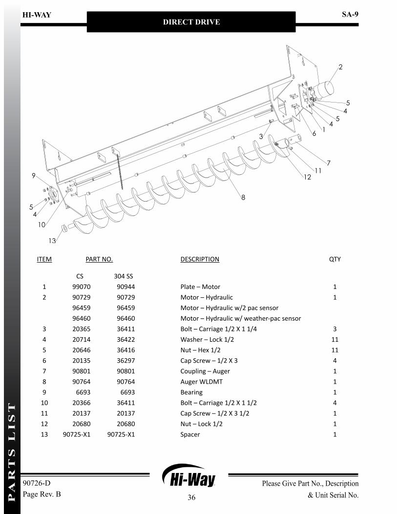
ITEM PART NO. DESCRIPTION QTY
CS 304 SS1 99070 90944 Plate – Motor 12 90729 90729 Motor – Hydraulic 1
96459 96459 Motor – Hydraulic w/2 pac sensor96460 96460 Motor – Hydraulic w/ weather-pac sensor
3 20365 36411 Bolt – Carriage 1/2 X 1 1/4 34 20714 36422 Washer – Lock 1/2 115 20646 36416 Nut – Hex 1/2 116 20135 36297 Cap Screw – 1/2 X 3 47 90801 90801 Coupling – Auger 18 90764 90764 Auger WLDMT 19 6693 6693 Bearing 1
10 20366 36411 Bolt – Carriage 1/2 X 1 1/2 411 20137 20137 Cap Screw – 1/2 X 3 1/2 112 20680 20680 Nut – Lock 1/2 113 90725-X1 90725-X1 Spacer 1
90726-DPage Rev. BPA
RT
S L
IS
T

37
HI-WAY
Please Give Part No., Description & Unit Serial No.
SA-9HEADER
90726-FPage Rev. A
WORM GEAR DRIVE
9
8
12
7
13
1
32
11
6
32
1
1415
10
4
5
2
ITEM PART NO. DESCRIPTION QTY
CS 304 SS1 20365 36411 Bolt – Carriage 1/2 X 1 1/4 72 20714 36422 Washer – Lock 1/2 113 20646 36416 Nut – Hex 1/2 74 20129 36539 Cap Screw – 1/2 X 1 1/2 45 90764 90764 Auger WLDMT 16 6693 6693 Bearing 17 90755 90943 Plate – Gear Case 18 71825 71825 Gear Case Assembly 19 37337 37337 Motor – Hydraulic 1
10 90795 90795 Bushing – Auger 111 90725 90725 Spacer 112 20137 34581 Cap Screw – 1/2 X 3 1/2 113 20680 39016 Nut – Lock 1/2 114 20067 36398 Cap Screw – 3/8 X 1 415 20712 36420 Washer – Lock 3/8 4
PA
RT
S L
IS
T

38
Please Give Part No., Description & Unit Serial No.
HI-WAY SA-9HEADER
90726-FPage Rev. A
GEAR CASEP
AR
TS
LI
ST

39
HI-WAY
Please Give Part No., Description & Unit Serial No.
SA-9HEADER
90726-FPage Rev. A
GEAR CASE CONTINUED
ITEM PART NO. DESCRIPTION QTY
71825 Gear Case Assy 11 58985 Housing 12 24230 Bearing - Cone 2
24225 Bearing - Cup 23 22832 Ring - Snap 24 22831 Seal - Output 15 58987 Shaft - Output 16 24231 Ring - Snap 17 22839 Cap 18 22824 Cover 19 22834 Gasket - Cover 1
10 22825 Gear - Worm 111 58988 Key - Woodruff 112 22840 Bearing - Cone 2
24225 Bearing - Cup 213 8621 Plug - Vent 114 6031 Plug - Level 115 20065 Cap Screw - 3/8 x 3/4 416 71458 Seal - Input 117 58989 Gasket 118 34995 Key 119 58986 Pin - Roll 120 83585 Mount - Motor 121 71105 Coupling 122 22826 Worm 123 6293 Plug - Drain 124 6089 Ring - Snap 125 58989 Gasket 126 71454 End 127 71456 Shaft - Input 128 24234 Key - Woodruff 129 20066 Cap Screw - 3/8 x 7/8 830 22835 Shim AR
AR - As Required
PA
RT
S L
IS
T

40
Please Give Part No., Description & Unit Serial No.
HI-WAY SA-9HEADER
90726-FPage Rev. A
WORM GEAR MOTOR
ITEM PART NO. DESCRIPTION QTY
70927 Motor - Hydraulic1 30665 Cap Screw - 5/16 x 7/8 42 37382 Seal 13 37383 Flange - Mounting 14 37378 Seal 15 37379 Seal - O-Ring 16 37385 Bearing - Spacer 17 37401 Bearing - Thrust Needle 18 3065 Key - Woodruff 19 37386 Shaft - Output 1
10 37380 Seal - O-Ring 311 16945 Drive 112 37388 Plate - Spacer 113 37391 Gerotor 114 37400 Cap - End 115 37381 Washer - Seal 716 16933 Cap Screw 717 * 22068 Seal - O-Ring 1
37352 Kit - Seal, Includes Items 2,4,5,10,15,17* - Not Shown
PA
RT
S L
IS
T
41
HI-WAY
Please Give Part No., Description & Unit Serial No.
SA-9HEADER
90726-FPage Rev. A
SPINNER MOTOR
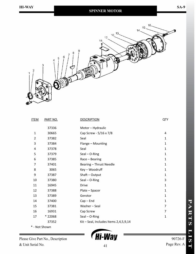
ITEM PART NO. DESCRIPTION QTY
37336 Motor – Hydraulic 1 30665 Cap Screw - 5/16 x 7/8 42 37382 Seal 13 37384 Flange – Mounting 14 37378 Seal 15 37379 Seal – O-Ring 16 37385 Race – Bearing 17 37401 Bearing – Thrust Needle 18 3065 Key – Woodruff 19 37387 Shaft – Output 1
10 37380 Seal – O-Ring 311 16945 Drive 112 37388 Plate – Spacer 113 37389 Gerotor 114 37400 Cap – End 115 37381 Washer – Seal 716 16931 Cap Screw 717 * 22068 Seal – O-Ring 1
37352 Kit – Seal, Includes Items 2,4,5,9,14* - Not Shown
PA
RT
S L
IS
T

42
Please Give Part No., Description & Unit Serial No.
HI-WAY SA-9HEADER
90726-FPage Rev. A
HYDRAULIC SYSTEM
40
ITEM PART NO. DESCRIPTION QTY
1 6011 Elbow - Pipe 90° 12 16582 End - Hose 13 6335 Clamp - Hose 44 23184-72 Hose - Suction (Trans. PTO) 1
23184-144 Hose - Suction (Electric Clutch) 15 16572 End - Hose (Trans. PTO) 1
16582 End - Hose (Electric Clutch) 16 56508 End - Hose 27 56459-72 Hose - Hydraulic (Trans. PTO) 1
56459-120 Hose - Hydraulic (Electric Clutch) 18 22425 End - Hose 39 11424 End - Hose 3
10 22381 Clamp - Hose 511 16529-144 Hose - Return 112 56453-144 Hose - Hydraulic 213 31599 End - Hose 214 56485 End - Hose 90° 2
NOTE: Illustration shows left-hand discharge.
PA
RT
S L
IS
T
43
HI-WAY
Please Give Part No., Description & Unit Serial No.
SA-9HEADER
90726-FPage Rev. A
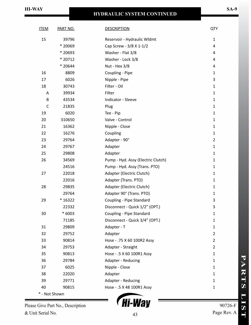
HYDRAULIC SYSTEM CONTINUED
ITEM PART NO. DESCRIPTION QTY
15 39796 Reservoir - Hydraulic Wldmt 1* 20069 Cap Screw - 3/8 X 1-1/2 4* 20693 Washer - Flat 3/8 4* 20712 Washer - Lock 3/8 4* 20644 Nut - Hex 3/8 4
16 8809 Coupling - Pipe 117 6026 Nipple - Pipe 318 30743 Filter - Oil 1
A 39934 Filter 1B 43534 Indicator - Sleeve 1C 21835 Plug 1
19 6020 Tee - Pip 120 310650 Valve - Control 121 16362 Nipple - Close 122 16276 Coupling 123 29764 Adapter - 90° 224 29767 Adapter 125 29808 Adapter 126 34569 Pump - Hyd. Assy (Electric Clutch) 1
24516 Pump - Hyd. Assy (Trans. PTO) 127 22018 Adapter (Electric Clutch) 1
22016 Adapter (Trans. PTO) 128 29835 Adapter (Electric Clutch) 1
29764 Adapter 90° (Trans. PTO) 129 * 16322 Coupling - Pipe Standard 3
22332 Disconnect - Quick 1/2” (OPT.) 330 * 6003 Coupling - Pipe Standard 1
71185 Disconnect - Quick 3/4” (OPT.) 131 29809 Adapter - T 132 29752 Adapter 233 90814 Hose - .75 X 60 100R2 Assy 234 29753 Adapter - Straight 235 90813 Hose - .5 X 60 100R1 Assy 136 29784 Adapter - Reducing 137 6025 Nipple - Close 138 22020 Adapter 139 29771 Adapter - Reducing 140 90815 Hose - .5 X 48 100R1 Assy 1
* - Not Shown
PA
RT
S L
IS
T

44
Please Give Part No., Description & Unit Serial No.
HI-WAY SA-9HEADER
90726-FPage Rev. A
CONTROL VALVEP
AR
TS
LI
ST

45
HI-WAY
Please Give Part No., Description & Unit Serial No.
SA-9HEADER
90726-FPage Rev. A
CONTROL VALVE CONTINUED
ITEM PART NO. DESCRIPTION QTY
34144 Valve – Control (10 - 15 GPM)34142 On/Off Valve Assembly, Includes Items 17-22
1 72590 Screw 22 72591 Knob – Hand 23 72592 Pin – Dowel 24 72593 Pin – Roll 25 72594 Spring 26 NSS O-Ring – Viton 27 NSS Back-up – Teflon 28 NSS O-Ring – Viton 29 72599 Auger Adjust Assembly 1
10 72589 Spinner Adjust Assembly 111 16964 Cartridge – Relief 112 NSS Gasket 113 NSS O-Ring – Viton 114 NSS Back-up – Teflon 215 NSS O-Ring – Viton 116 20918 Pin – Roll 217 NSS O-Ring – Dump Stem 118 NSS Stem 119 NSS Plug 120 20748 Screw – Set 121 34148 Knob – Hand 122 34147 Lever 123 16960 Bypass Assembly 124 NSS O-Ring – Viton 2
72597 Kit – Seal, Inc. Items 6-8, 12-15, 17, 24NSS - Not Sold Separately
PA
RT
S L
IS
T

46
Please Give Part No., Description & Unit Serial No.
HI-WAY SA-9HEADER
90726-FPage Rev. A
PUMP KIT (ELECTRIC CLUTCH)
ITEM PART NO. DESCRIPTION QTY
71196 Kit – Pump w/ Electric Clutch1 34569 Pump – Hydraulic with Elec. Clutch Assy 1
34577 Pump – Hydraulic 134570 Clutch – Electric 134571 Bracket – Mounting 1
2 21679 Terminal – Spade 13 6549 Connector – Butt 14 21580-120 Wire – Black, 14 Ga. 15 21681 Switch – Toggle 16 22018 Adapter 17 29835 Adapter 1
PA
RT
S L
IS
T
47
HI-WAY
Please Give Part No., Description & Unit Serial No.
SA-9HEADER
90726-FPage Rev. A
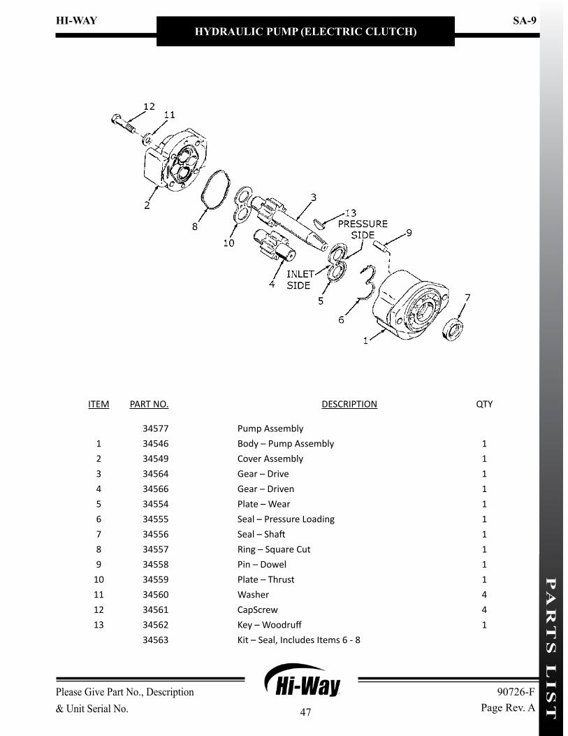
HYDRAULIC PUMP (ELECTRIC CLUTCH)
ITEM PART NO. DESCRIPTION QTY
34577 Pump Assembly1 34546 Body – Pump Assembly 12 34549 Cover Assembly 13 34564 Gear – Drive 14 34566 Gear – Driven 15 34554 Plate – Wear 16 34555 Seal – Pressure Loading 17 34556 Seal – Shaft 18 34557 Ring – Square Cut 19 34558 Pin – Dowel 1
10 34559 Plate – Thrust 111 34560 Washer 412 34561 CapScrew 413 34562 Key – Woodruff 1
34563 Kit – Seal, Includes Items 6 - 8
PA
RT
S L
IS
T

48
Please Give Part No., Description & Unit Serial No.
HI-WAY SA-9HEADER
90726-FPage Rev. A
HYDRAULIC PUMP
ITEM PART NO. DESCRIPTION QTY
24516 Pump – Hydraulic Assembly1 5676 Housing – Gear 12 5680 Pin – Dowel 23 58621 Plate – End 14 58622 Gear – Idler 15 5665 Plate – Wear 26 5678 Seal – Ring 27 5666 Washer – Backup 28 5677 Seal – Preload 29 58623 Plate – End 1
10 5682 Shaft – Drive 111 6137 Key – Square 112 58624 Flange 213 5685 O-Ring 214 5683 Bolt – Socket Head 615 58625 Washer 616 58626 Bolt – Socket Head 4
3904 Kit – Seal, Includes Items 5-8, 11, 13
PA
RT
S L
IS
T

49
HI-WAY
Please Give Part No., Description & Unit Serial No.
SA-9HEADER
90726-FPage Rev. A
MOUNTING KIT - PUMP (TRANSMISSION PTO)
ITEM PART NO. DESCRIPTION QTY
1 2211 Key – Square 12 6069 Zerk – Grease 13 6123 Pin – Shear 14 20085 Cap Screw - 3/8 x 5 1/2 25 20712 Washer – Lock 3/8 26 20817 Pin – Cotter 17 22337 Bracket – Mounting WLDMT 18 22465 U-Joint 19 56745 U-Joint 1
10 17932 Shaft – Drive 111 20644 Nut – Hex 3/8 2
PA
RT
S L
IS
T

50
Please Give Part No., Description & Unit Serial No.
HI-WAY SA-9HEADER
90726-FPage Rev. A
T - TANK P - PUMP PRESSURE S - SPINNER A - AUGER/CONVEYOR
ITEM PART NO. DESCRIPTION QTY
1 20013 Cap Screw - 1/4 x 3 22 29752 Adapter 33 29784 Adapter 14 36803 Mount – Valve WLDMT 15 36800 Tube – Hydraulic 46 29799 Adapter – Bushing 47 29808 Adapter 1
PEDESTAL MOUNT KITP
AR
TS
LI
ST

51
HI-WAY
Please Give Part No., Description & Unit Serial No.
SA-9HEADER
90726-FPage Rev. A
B
2
3
3
37
1515
3 7
11
4-6
8 9
10
3
1
12-14
ITEM PART NO. DESCRIPTION QTY
CS 304 SS1 96762 96844 Brace - Mounting 22 96780 96825 Boss 23 40576 40576 Pin - Hair 64 20129 36539 Cap Screw – 1/2 X 1 1/2 85 20714 36422 Washer - Lock 1/2 86 20646 36416 Nut - Hex 1/2 87 20695 36426 Washer - Flat 1/2 88 23244 23244-X1 Mount - Spreader Half Wldmt 29 23236 23236-X1 Mount - Truck Half Wldmt 2
10 23248 23248-X1 Rod - Lock Pin 211 204120 90963 Bar - Stabilizer 112 20067 36398 Cap Screw – 3/8 X 1 213 20712 36420 Washer - Lock 3/8 214 20644 36414 Nut - Hex 3/8 215 204121 90964 Rod - Link, Stabilizer 2
MOUNTING - QUICK DISCONNECT KITP
AR
TS
LI
ST

52
Please Give Part No., Description & Unit Serial No.
HI-WAY SA-9HEADER
90726-FPage Rev. A
ITEM PART NO. DESCRIPTION QTY
1 39870 Decal - Hi-Way 12 90805 Decal - SA-9 13 150034 Decal - Caution, Operation & Maintenance 14 55997 Decal - Danger, Moving Part Hazard 25 321 Decal - Caution, Hazardous Material 16 83649 Decal - Danger, Flying Material 17 55631 Decal - Warning, Moving Part Hazard 28 39138 Decal - Warning, High Pressure Fluid 19 37285 Serial Plate - HECO 1
10 6276 Screw - Drive #4 x 1/4 4
DECALSP
AR
TS
LI
ST