model :rt40ma / mb rt44ma / mb
TRANSCRIPT
Model :RT40MA / MBRT44MA / MB
REFRIGERATOR CONTENTS
1. Product Specifications
2. Safety Warnings
3. Specifications of Electric Components
4. Electric Circuit Diagram
5. External Size and Designations
6. Refrigeration Cycle and Cool Air Circulation
7. Circuit Operation Theory
8. Troubleshooting
9. Exploded View and Part List
10. Disassembly of Freezing Compartment
11. Disassembly of Refrigerating Compartment
1
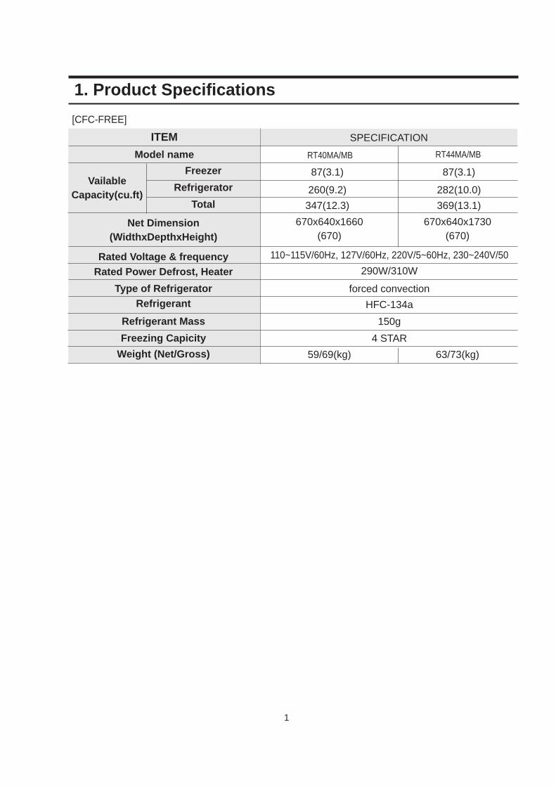
1. Product Specifications
ITEM
Model name
SPECIFICATION
Freezer
Refrigerator
Total
RT40MA/MB RT44MA/MB
87(3.1) 87(3.1)
260(9.2) 282(10.0)
347(12.3)
110~115V/60Hz, 127V/60Hz, 220V/5~60Hz, 230~240V/50
290W/310W
forced convection
HFC-134a
150g
4 STAR
369(13.1)
670x640x1660(670)
670x640x1730(670)
59/69(kg) 63/73(kg)
VailableCapacity(cu.ft)
Net Dimension(WidthxDepthxHeight)
Rated Voltage & frequencyRated Power Defrost, Heater
Type of RefrigeratorRefrigerant
Refrigerant Mass
Freezing Capicity
Weight (Net/Gross)
[CFC-FREE]
2
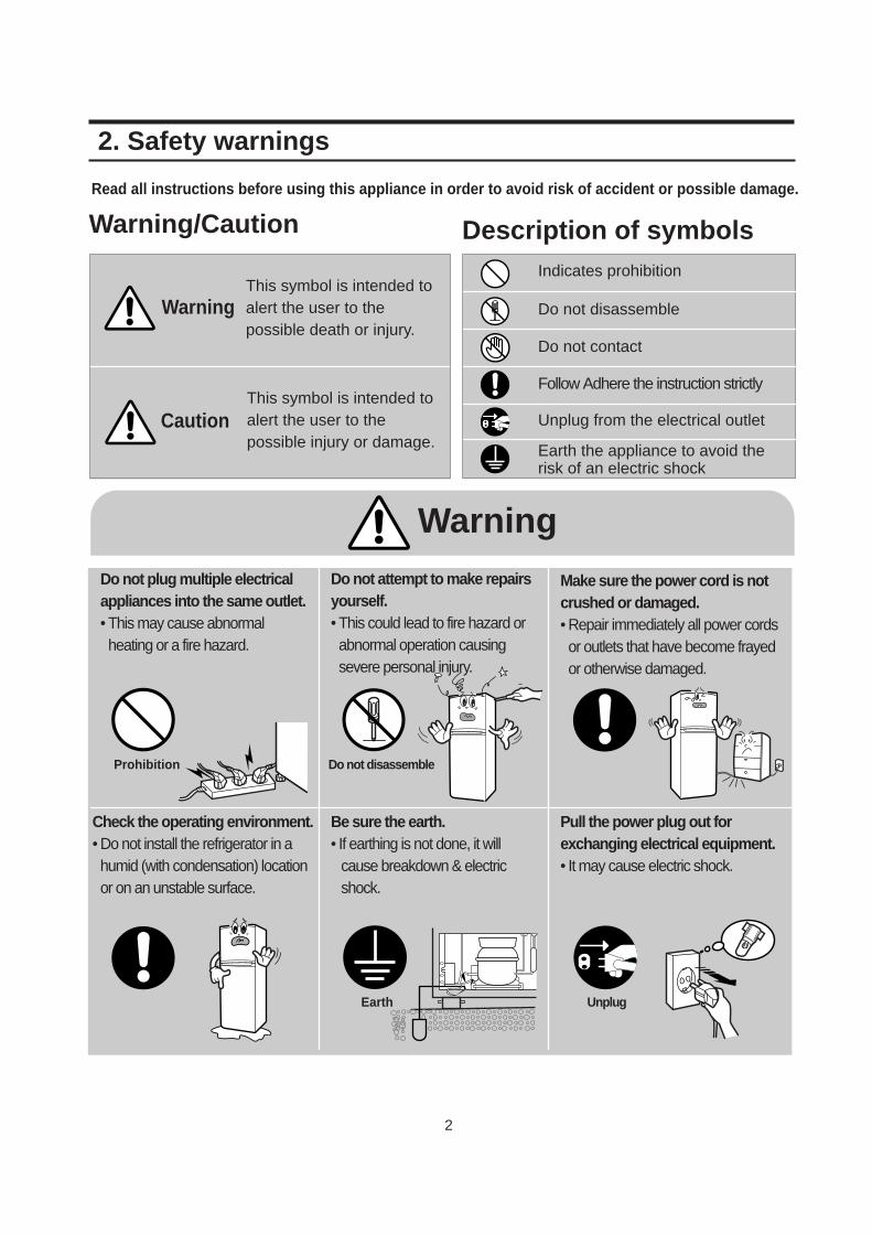
2. Safety warnings
Read all instructions before using this appliance in order to avoid risk of accident or possible damage.
Warning/Caution Description of symbolsIndicates prohibition
Do not disassemble
Do not contact
Follow Adhere the instruction strictly
Unplug from the electrical outlet
Earth the appliance to avoid therisk of an electric shock
Do not plug multiple electricalappliances into the same outlet.• This may cause abnormalheating or a fire hazard.
Do not attempt to make repairsyourself.• This could lead to fire hazard orabnormal operation causingsevere personal injury.
Make sure the power cord is notcrushed or damaged.• Repair immediately all power cordsor outlets that have become frayedor otherwise damaged.
Check the operating environment.• Do not install the refrigerator in ahumid (with condensation) locationor on an unstable surface.
Be sure the earth.• If earthing is not done, it will
cause breakdown & electricshock.
Pull the power plug out for exchanging electrical equipment.• It may cause electric shock.
WarningThis symbol is intended toalert the user to thepossible death or injury.
CautionThis symbol is intended toalert the user to thepossible injury or damage.
Warning
Prohibition Do not disassemble
Earth Unplug
3
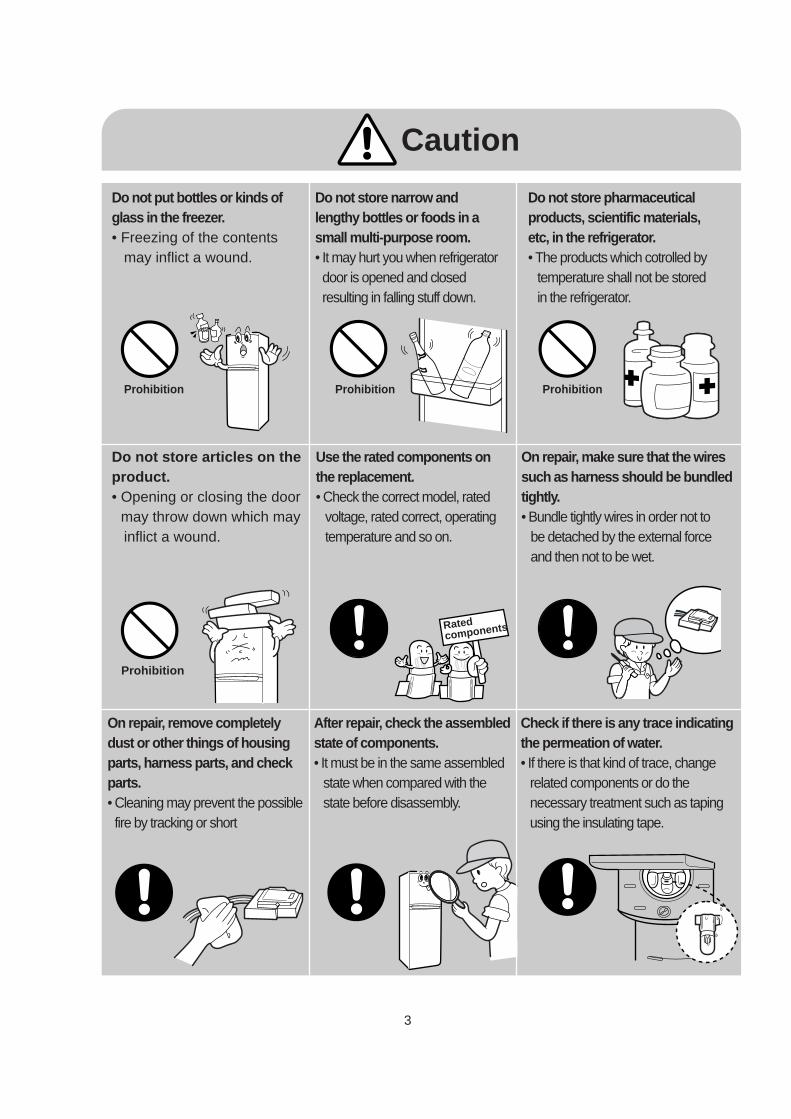
Caution
Do not put bottles or kinds ofglass in the freezer.• Freezing of the contents
may inflict a wound.
Do not store narrow andlengthy bottles or foods in a small multi-purpose room.• It may hurt you when refrigeratordoor is opened and closedresulting in falling stuff down.
Do not store pharmaceuticalproducts, scientific materials, etc, in the refrigerator.• The products which cotrolled by
temperature shall not be stored in the refrigerator.
Do not store articles on the product.• Opening or closing the door
may throw down which mayinflict a wound.
Use the rated components onthe replacement.• Check the correct model, rated
voltage, rated correct, operatingtemperature and so on.
On repair, make sure that the wiressuch as harness should be bundled tightly.• Bundle tightly wires in order not to
be detached by the external forceand then not to be wet.
On repair, remove completelydust or other things of housingparts, harness parts, and checkparts.• Cleaning may prevent the possiblefire by tracking or short
After repair, check the assembledstate of components.• It must be in the same assembled
state when compared with thestate before disassembly.
Check if there is any trace indicatingthe permeation of water.• If there is that kind of trace, change
related components or do the necessary treatment such as tapingusing the insulating tape.
Prohibition
Prohibition
Prohibition Prohibition
Rated components
4
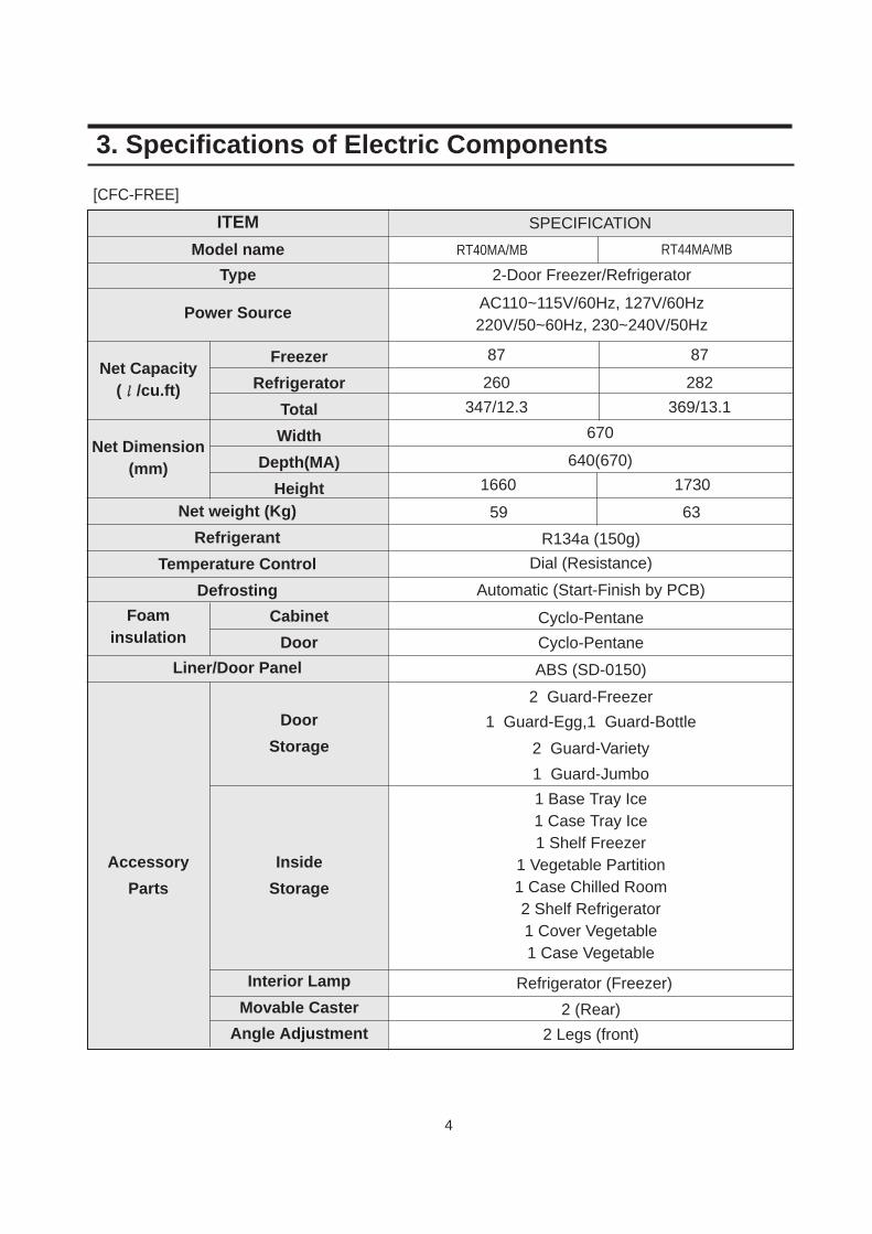
1 Base Tray Ice1 Case Tray Ice1 Shelf Freezer
1 Vegetable Partition1 Case Chilled Room2 Shelf Refrigerator1 Cover Vegetable1 Case Vegetable
ITEM
Model name
Type
Power Source
SPECIFICATION
Freezer
Refrigerator
Total
Width
Depth(MA)
HeightNet weight (Kg)
Refrigerant
Temperature Control
Defrosting
Cabinet
Door
Door
Storage
Accessory
Parts
Inside
Storage
Angle Adjustment
Movable Caster
Interior Lamp
Liner/Door Panel
RT40MA/MB RT44MA/MB
87 87
260 282
347/12.3 369/13.1
670
640(670)
17301660
59 63
R134a (150g)
Dial (Resistance)
Automatic (Start-Finish by PCB)
Cyclo-Pentane
Cyclo-Pentane
ABS (SD-0150)
2 Guard-Freezer
1 Guard-Egg,1 Guard-Bottle
2 Guard-Variety
1 Guard-Jumbo
Refrigerator (Freezer)
2 (Rear)
2 Legs (front)
2-Door Freezer/Refrigerator
AC110~115V/60Hz, 127V/60Hz220V/50~60Hz, 230~240V/50Hz
3. Specifications of Electric Components
Net Capacity(ℓℓ/cu.ft)
Net Dimension(mm)
Foaminsulation
[CFC-FREE]
5
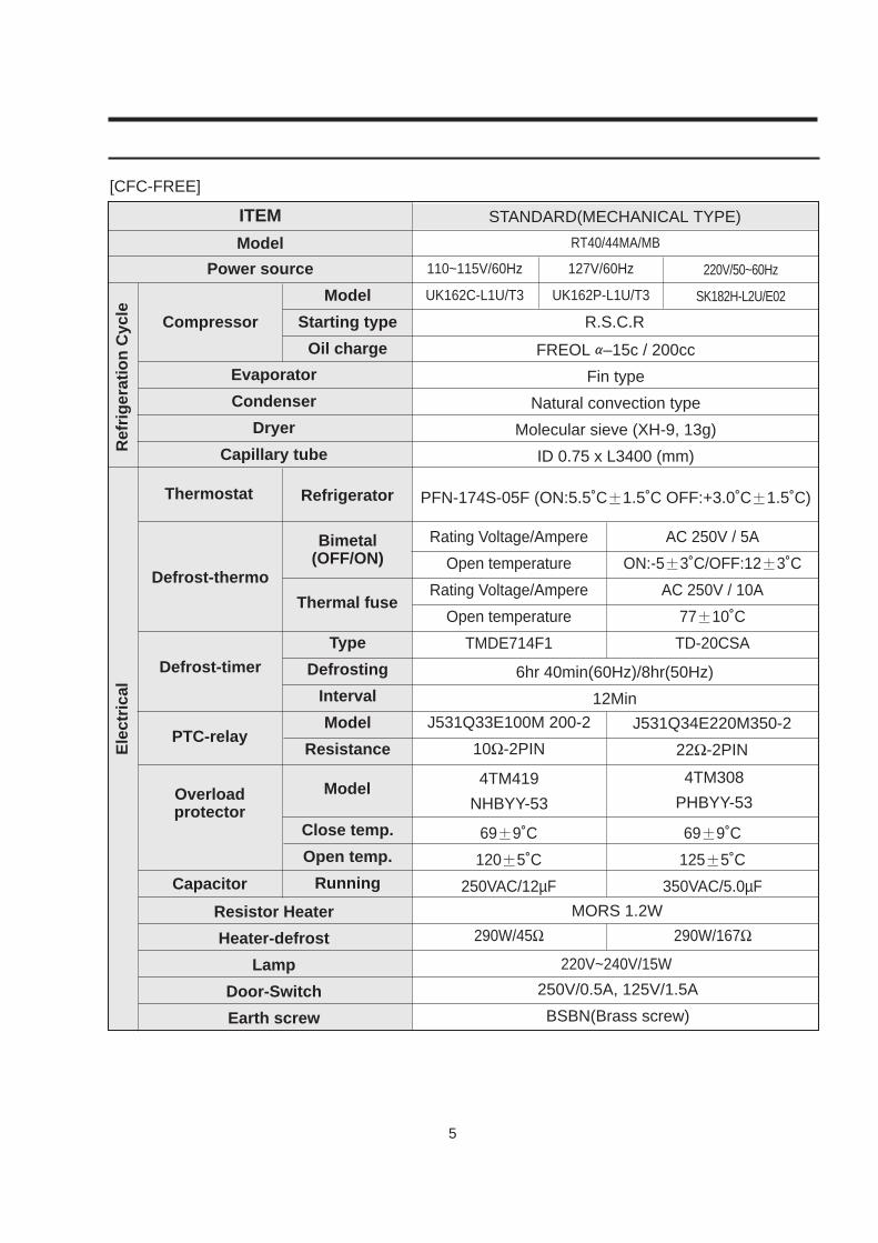
[CFC-FREE]
ITEM
Model
Power source
STANDARD(MECHANICAL TYPE)
Evaporator
Condenser
Dryer
Capillary tube
Resistor Heater
Heater-defrost
Lamp
Door-Switch
Earth screw
Model
Starting type
Oil charge
Compressor
Refrigerator
Thermal fuse
Model
Thermostat
Bimetal(OFF/ON)
Defrost-thermo
PTC-relay
Capacitor
Overloadprotector
Type
Defrosting
Interval
Model
Resistance
Close temp.
Open temp.
Running
Defrost-timer
Ref
rig
erat
ion
Cyc
leE
lect
rica
l
R.S.C.R
110~115V/60Hz
UK162C-L1U/T3
127V/60Hz
UK162P-L1U/T3
220V/50~60Hz
SK182H-L2U/E02
FREOL α–15c / 200cc
Fin type
Natural convection type
Molecular sieve (XH-9, 13g)
ID 0.75 x L3400 (mm)
PFN-174S-05F (ON:5.5˚C±1.5˚C OFF:+3.0˚C±1.5˚C)
250V/0.5A, 125V/1.5A
BSBN(Brass screw)
Rating Voltage/Ampere
Open temperature
Rating Voltage/Ampere
Open temperature
TMDE714F1
AC 250V / 5A
ON:-5±3˚C/OFF:12±3˚C
AC 250V / 10A
77±10˚C
TD-20CSA
69±9˚C
120±5˚C
250VAC/12µF
69±9˚C
125±5˚C
350VAC/5.0µF
J531Q33E100M 200-2
10Ω-2PIN
6hr 40min(60Hz)/8hr(50Hz)
12Min
J531Q34E220M350-2
22Ω-2PIN
4TM419
NHBYY-53
4TM308
PHBYY-53
MORS 1.2W
290W/45Ω 290W/167Ω
220V~240V/15W
RT40/44MA/MB
6
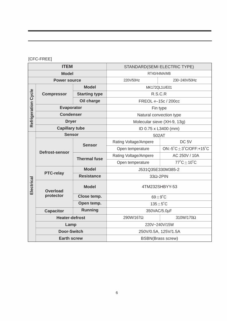
[CFC-FREE]
ITEM
Model
Power source
STANDARD(SEMI ELECTRIC TYPE)
Evaporator
Condenser
Dryer
Capillary tube
Heater-defrost
Lamp
Door-Switch
Earth screw
Model
Starting type
Oil charge
Compressor
Sensor
Thermal fuse
Model
Sensor
Defrost-sensor
PTC-relay
Capacitor
Overloadprotector
Model
Resistance
Close temp.
Open temp.
Running
Ref
rig
erat
ion
Cyc
leE
lect
rica
l
R.S.C.R
220V/50Hz 230~240V/50Hz
MK172QL1U/E01
FREOL α–15c / 200cc
Fin type
Natural convection type
Molecular sieve (XH-9, 13g)
ID 0.75 x L3400 (mm)
502AT
Rating Voltage/Ampere
Open temperature
Rating Voltage/Ampere
Open temperature
DC 5V
ON:-5˚C±3˚C/OFF:+15˚C
AC 250V / 10A
77˚C±10˚C
J531Q35E330M385-2
33Ω-2PIN
69±9˚C
135±5˚C
350VAC/5.0µF
4TM232SHBYY-53
290W/167Ω 310W/170Ω
220V~240V/15W
250V/0.5A, 125V/1.5A
BSBN(Brass screw)
RT40/44MA/MB
7
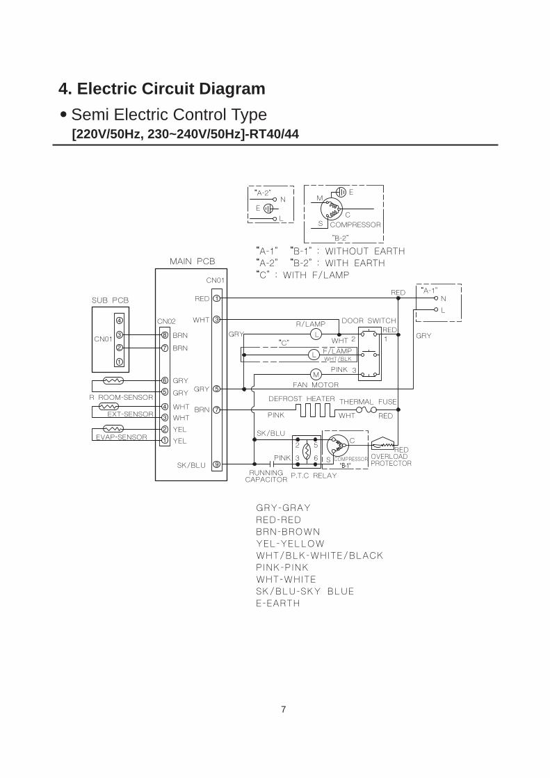
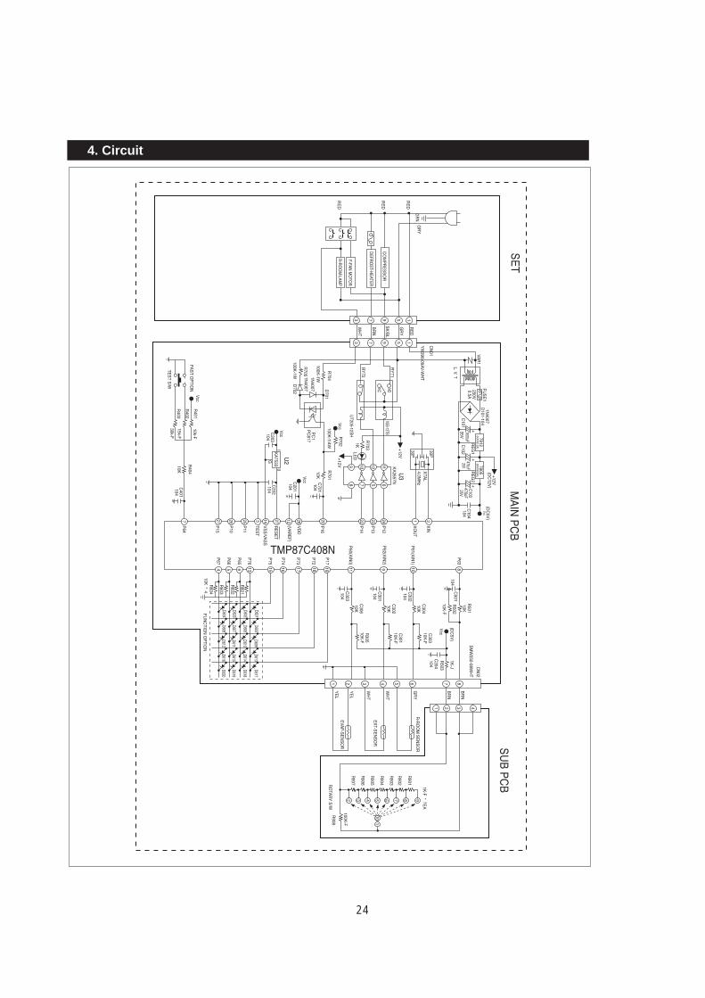
4. Electric Circuit Diagram Semi Electric Control Type
SUB PCB
MAIN PCB
CN01
R ROOM-SENSOR
EXT-SENSOR
EVAP-SENSOR
SK/BLURUNNING
CAPACITOR P.T.C RELAY
PINK
SK/BLU
PINK
2 5
S
C
COMPRESSOR
RED
WHT
THERMAL FUSEDEFROST HEATER
FAN MOTOR
PINK 3
12WHT
R/LAMPGRY
DOOR SWITCHRED
REDN
L
NE
L
EM
SC
COMPRESSOR
"B-2"
“A-2"
“A-1"
GRY
F/LAMPL
L
WHT/BLK
M
RED
OVERLOADPROTECTOR
3 6
YEL
YEL
WHTWHT
GRY
GRY
BRN
BRN
RED
WHT
GRY
BRN
CN02
CN01
“A-1" “B-1" : WITHOUT EARTH“A-2" “B-2" : WITH EARTH“C" : WITH F/LAMP
GRY-GRAYRED-REDBRN-BROWNYEL-YELLOWWHT/BLK-WHITE/BLACKPINK-PINKWHT-WHITESK/BLU-SKY BLUEE-EARTH
“C"
[220V/50Hz, 230~240V/50Hz]-RT40/44
8
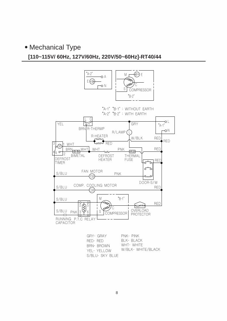
Mechanical Type
YEL
WHTMBRN
BIMETALDEFROSTTIMER
RUNNINGCAPACITOR
P.T.C RELAYCOMPRESSOR
COMPRESSOR
OVERLOADPROTECTOR
WHT
BRN R-THERMP
R-HEATERR/LAMP
GRYL
N
EA
N
M
SC
E
W/BLK RED
RED
RED
RED
PNKS/BLU
S/BLU
S/BLU PNK
2
3
5
M
SC
RED
GRY- GRAY RED- REDBRN- BROWNYEL- YELLOWS/BLU- SKY BLUE
PNK- PINKBLK- BLACKWHT- WHITEW/BLK- WHITE/BLACK
6
FAN MOTOR
COMP. COOLING MOTORDOOR-S/W
F.M
S/BLUC.M
RED
“A-1"
“A-2"
“B-2"
“A-1" “B-1" : WITHOUT EARTH“A-2" “B-2" : WITH EARTH
“B-1"
L
RED
L CH
WHT PNK
THERMALFUSE
DEFROSTHEATER
13
4 2
[110~115V/ 60Hz, 127V/60Hz, 220V/50~60Hz]-RT40/44
9
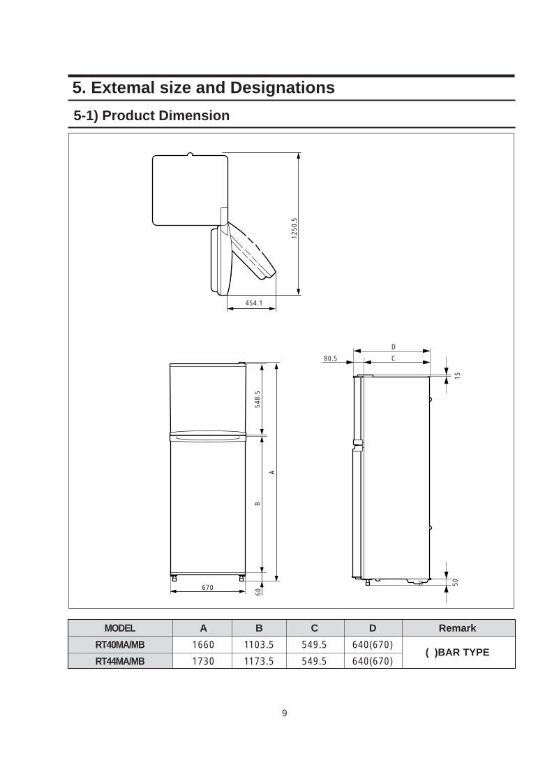
5-1) Product Dimension
670
60
9
B
A
548.
5
5015
C
D
80.5
1250
.5454.1
MODEL
RT40MA/MB
RT44MA/MB
A
1660
1730
B
1103.5
1173.5
C
549.5
549.5
D
640(670)
640(670)
Remark
( )BAR TYPE
5. Extemal size and Designations
10
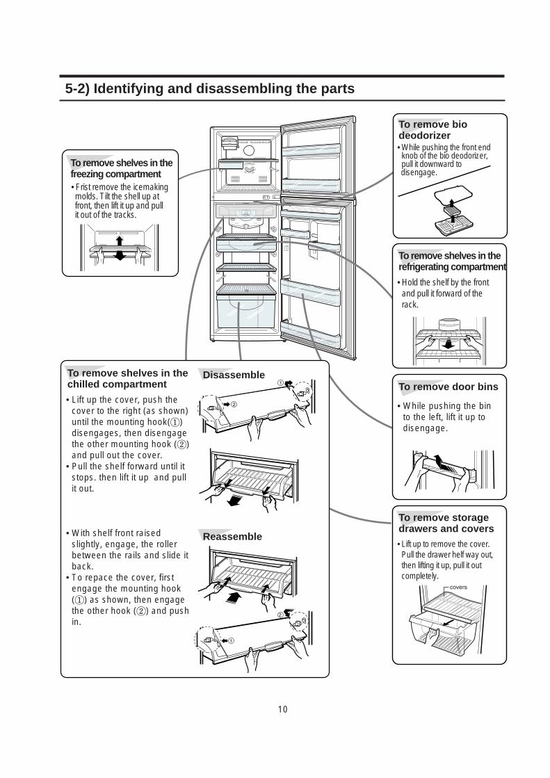
To remove shelves in thefreezing compartment• Frist remove the icemaking molds. Tilt the shell up at front, then lift it up and pull it out of the tracks.
To remove biodeodorizer• While pushing the front endknob of the bio deodorizer,pull it downward to disengage.
To remove shelves in therefrigerating compartment
• Hold the shelf by the frontand pull it forward of therack.
To remove shelves in thechilled compartment
Disassemble
Reassemble
• Lift up the cover, push thecover to the right (as shown)until the mounting hook(①)disengages, then disengagethe other mounting hook (②)and pull out the cover.
• Pull the shelf forward until itstops. then lift it up and pullit out.
• With shelf front raisedslightly, engage, the rollerbetween the rails and slide itback.
• To repace the cover, firstengage the mounting hook(①) as shown, then engagethe other hook (②) and pushin.
To remove door bins
• While pushing the binto the left, lift it up todisengage.
To remove storagedrawers and covers• Lift up to remove the cover.Pull the drawer helf way out,then lifting it up, pull it outcompletely.
5-2) Identifying and disassembling the parts
11
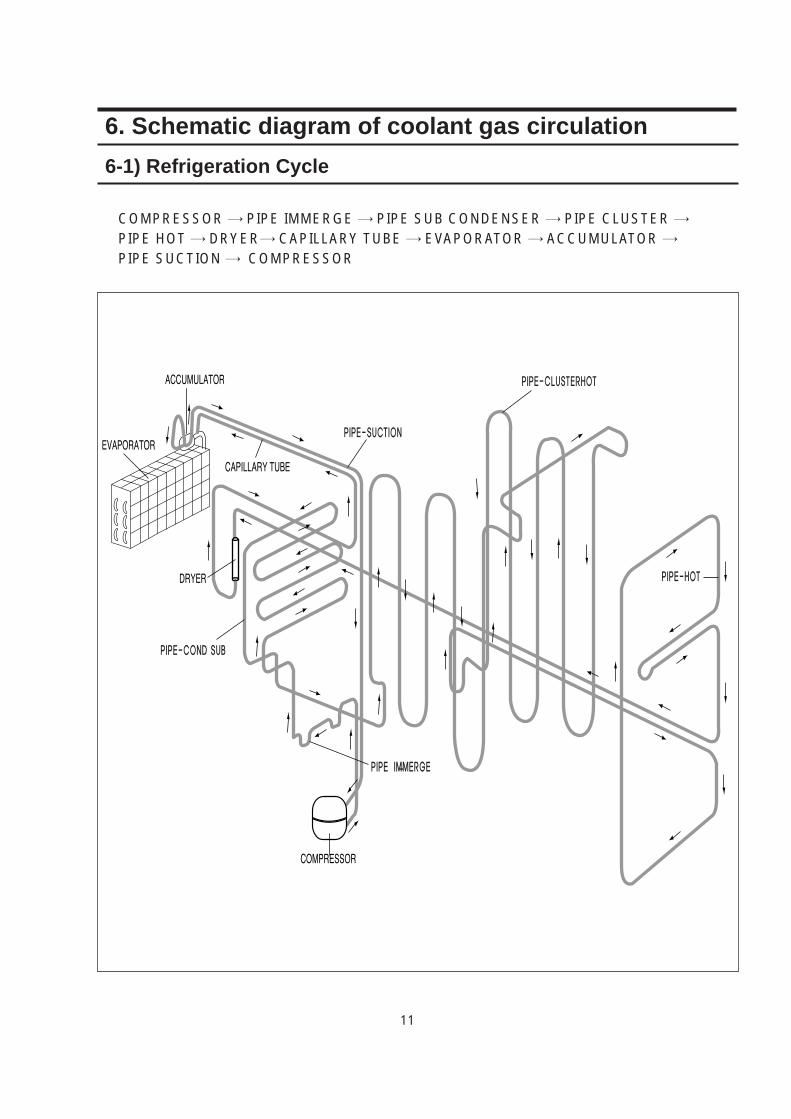
6. Schematic diagram of coolant gas circulation
COMPRESSOR → PIPE IMMERGE → PIPE SUB CONDENSER → PIPE CLUSTER →PIPE HOT → DRYER→ CAPILLARY TUBE → EVAPORATOR → ACCUMULATOR →PIPE SUCTION → COMPRESSOR
6-1) Refrigeration Cycle
12
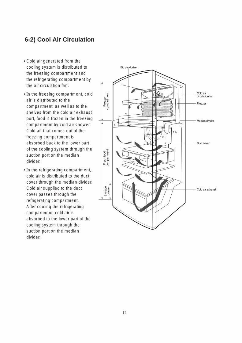
6-2) Cool Air Circulation
• Cold air generated from thecooling system is distributed tothe freezing compartment andthe refrigerating compartment bythe air circulation fan.
• In the freezing compartment, coldair is distributed to thecompartment as well as to theshelves from the cold air exhaustport, food is frozen in the freezingcompartment by cold air shower.
• Cold air that comes out of thefreezing compartment isabsorbed back to the lower partof the cooling system through thesuction port on the mediandivider.
• In the refrigerating compartment,cold air is distributed to the ductcover through the median divider.Cold air supplied to the ductcover passes through therefrigerating compartment.
• After cooling the refrigeratingcompartment, cold air isabsorbed to the lower part of thecooling system through thesuction port on the mediandivider.
Rotating blade
13
7. Circuit operation theory1. Temperature Control and Operational Description of Other Functions
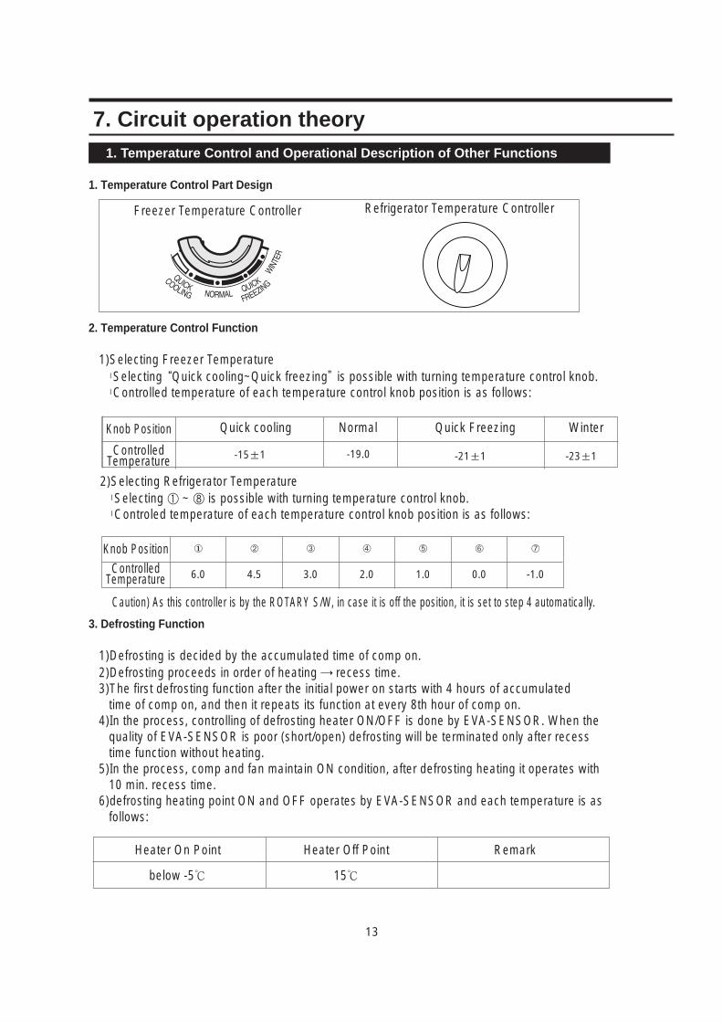
1. Temperature Control Part Design
2. Temperature Control Function
1)Selecting Freezer Temperaturel Selecting “Quick cooling~Quick freezing”is possible with turning temperature control knob. l Controlled temperature of each temperature control knob position is as follows:
Knob Position
Controlled Temperature -15±1
Normal
-19.0 -21±1 -23±1
2)Selecting Refrigerator Temperaturel Selecting ① ~ ⑧ is possible with turning temperature control knob.l Controled temperature of each temperature control knob position is as follows:
3. Defrosting Function
1)Defrosting is decided by the accumulated time of comp on.2)Defrosting proceeds in order of heating → recess time.3)The first defrosting function after the initial power on starts with 4 hours of accumulated
time of comp on, and then it repeats its function at every 8th hour of comp on.4)In the process, controlling of defrosting heater ON/OFF is done by EVA-SENSOR. When the
quality of EVA-SENSOR is poor (short/open) defrosting will be terminated only after recess time function without heating.
5)In the process, comp and fan maintain ON condition, after defrosting heating it operates with 10 min. recess time.
6)defrosting heating point ON and OFF operates by EVA-SENSOR and each temperature is as follows:
Caution) As this controller is by the ROTARY S/W, in case it is off the position, it is set to step 4 automatically.
Knob Position
Controlled Temperature
6.0
➁
4.5
➂
3.0
➃
2.0
➄
1.0
➅
0.0
➆
-1.0
Freezer Temperature Controller Refrigerator Temperature Controller
Heater On Point
below -5
Heater Off Point
15
Remark
Quick cooling Quick Freezing Winter
14
4. Testing Functionl This function is for PCB and test of products, work process test, and SVC.l After checking the product's function by selecting TEST S/W, let the self-diagnosis function
start with the POWER OFF and ON.
1)Forced Starting Functionl COMP and FAN starts immediately after the TEST S/W on the Main PCB is pressed once. So when the forced staring function is done right at the COMP OFF point, Over Load in the COMP may be caused. Extra caution is necessary.
l When forced starting function is selected, COMP and FAN run for 24 hours regardless of the freezer/refrigerator temperature and knob selection. Indicating Lamp on main PCB shows that it is a forced starting function by 0.5sec interval ON/OFF.
l When a selected forced starting function is selected and maintains for 24 hours, defrosting function starts its operation, and when defrosting is completed normal operation is carried out according to the temperature selection knob position.
l To release it's operation during forced starting, power should be turned off and turned on again or test release mode on 3) below should be selected.
2)Forced Defrosting Functionl If test switch is pressed once more during forced starting function, it is released immediately and forced defrosting function starts, and the Lamp on main PCB shows that it's forced defrosting by 1.0 sec. interval ON/OFF.l When forced defrosting is selected COMP and FAN is turned off immediately, and defrosting heater is turned on at the same time. At this moment if the sensed temperature of EVA-SENSOR is higher than -5.0, defrosting heater is not turned ON and operates only for recess time and returns to normal operation.
l When Heating is completed it recesses for 10 mints. and after that indicating Lamp remains ON and returns to normal operation.
3)Test Function Release ModeIf TEST S/W is pressed once more when forced defrosting function is carried out, forced defrosting is released and stops for 10 mints. and after that it returns to normal operation.
15
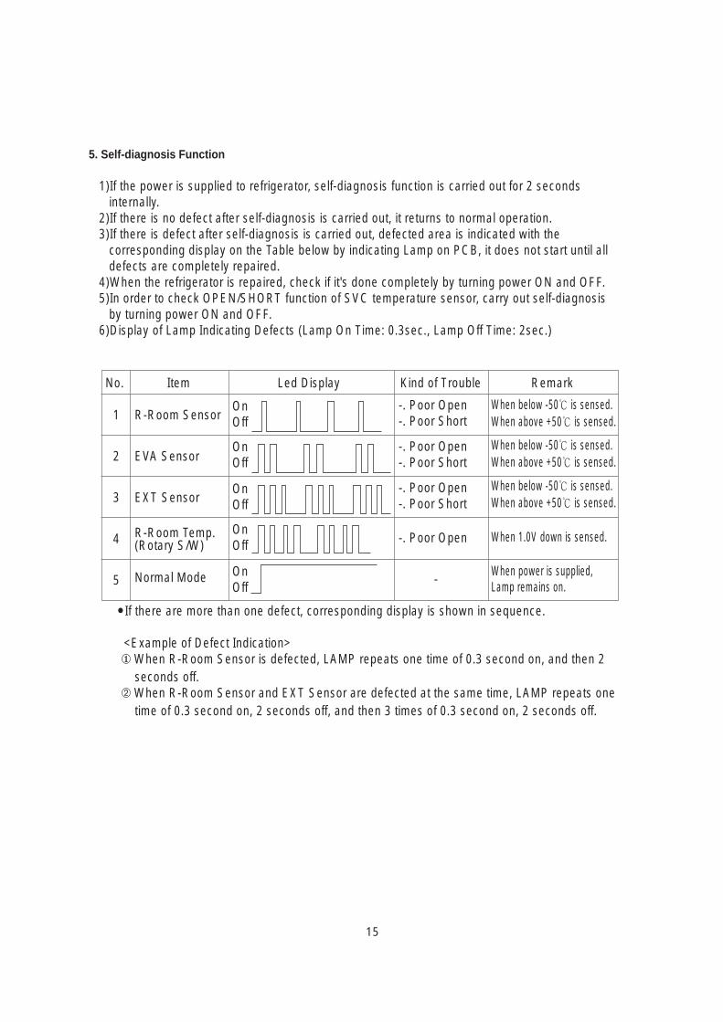
5. Self-diagnosis Function
1)If the power is supplied to refrigerator, self-diagnosis function is carried out for 2 seconds internally.
2)If there is no defect after self-diagnosis is carried out, it returns to normal operation.3)If there is defect after self-diagnosis is carried out, defected area is indicated with the
corresponding display on the Table below by indicating Lamp on PCB, it does not start until all defects are completely repaired.
4)When the refrigerator is repaired, check if it's done completely by turning power ON and OFF.5)In order to check OPEN/SHORT function of SVC temperature sensor, carry out self-diagnosis
by turning power ON and OFF. 6)Display of Lamp Indicating Defects (Lamp On Time: 0.3sec., Lamp Off Time: 2sec.)
If there are more than one defect, corresponding display is shown in sequence.
<Example of Defect Indication> When R-Room Sensor is defected, LAMP repeats one time of 0.3 second on, and then 2
seconds off.➁ When R-Room Sensor and EXT Sensor are defected at the same time, LAMP repeats one
time of 0.3 second on, 2 seconds off, and then 3 times of 0.3 second on, 2 seconds off.
1
2
3
4
5
R-Room Sensor
EVA Sensor
EXT Sensor
R-Room Temp.(Rotary S/W)
Normal Mode
OnOff
OnOff
OnOff
OnOff
OnOff
-. Poor Open-. Poor Short
-. Poor Open-. Poor Short
-. Poor Open-. Poor Short
-. Poor Open
-
When below -50 is sensed.When above +50 is sensed.
When below -50 is sensed.When above +50 is sensed.
When below -50 is sensed.When above +50 is sensed.
When 1.0V down is sensed.
When power is supplied, Lamp remains on.
No. Item Led Display RemarkKind of Trouble
16
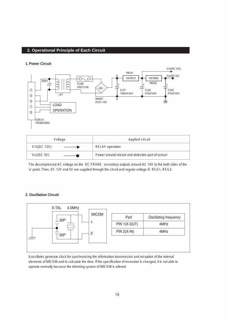
1. Power Circuit
2. Operational Principle of Each Circuit
Voltage
V12(DC 12V)
Vcc(DC 5V)
RELAY operation
Power around micom and detection part of sensor
Applied circuit
The decompressed AC voltage on the DC-TRANS secondary outputs around AC 16V to the both sides of the‘a’ point. Then, DC 12V and 5V are supplied through the circuit and regular voltage IC REG1, REG2.
It oscillates generate clock for synchronizing the information transmission and reception of the internalelements of MICOM and to calculate the time. If the specification of resonator is changed, it is not able tooperate normally because the trimming system of MICOM is altered.
2. Oscillation Circuit
17
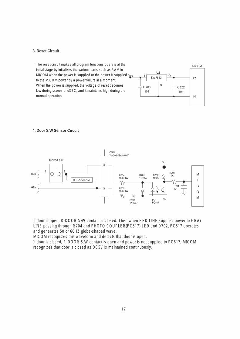
The reset circuit makes all program functions operate at theinitial stage by initializes the various parts such as RAM inMICOM when the power is supplied or the power is suppliedto the MICOM power by a power failure in a moment.When the power is supplied, the voltage of reset becomeslow during scores of uSEC, and it maintains high during thenormal operation.
If door is open, R-DOOR S/W contact is closed. Then when RED LINE supplies power to GRAYLINE passing through R704 and PHOTO COUPLER(PC817) LED and D702, PC817 operatesand generates 50 or 60HZ globe-shaped wave.MICOM recognizes this waveform and detects that door is open.If door is closed, R-DOOR S/W contact is open and power is not supplied to PC817, MICOMrecognizes that door is closed as DC5V is maintained continuously.
3. Reset Circuit
4. Door S/W Sensor Circuit
18
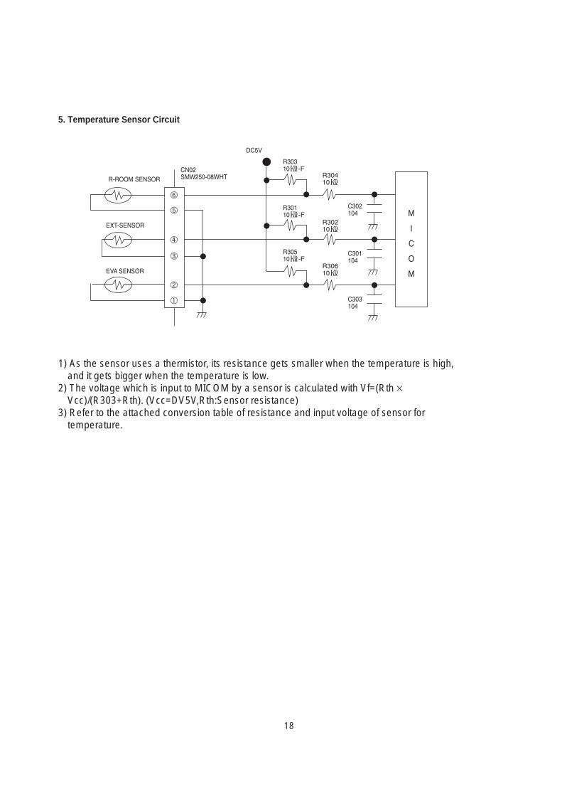
5. Temperature Sensor Circuit
1) As the sensor uses a thermistor, its resistance gets smaller when the temperature is high,and it gets bigger when the temperature is low.
2) The voltage which is input to MICOM by a sensor is calculated with Vf=(Rth×Vcc)/(R303+Rth). (Vcc=DV5V,Rth:Sensor resistance)
3) Refer to the attached conversion table of resistance and input voltage of sensor fortemperature.
19
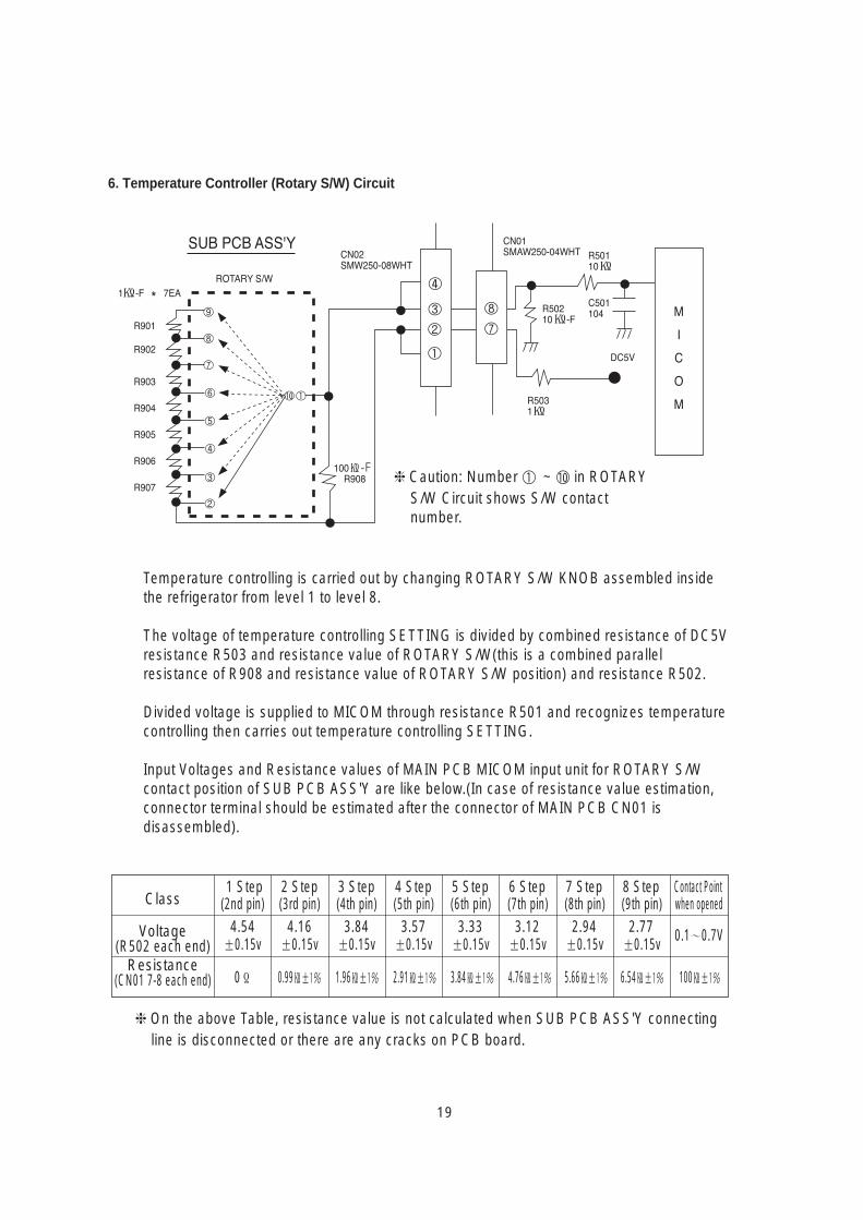
6. Temperature Controller (Rotary S/W) Circuit
Temperature controlling is carried out by changing ROTARY S/W KNOB assembled insidethe refrigerator from level 1 to level 8.
The voltage of temperature controlling SETTING is divided by combined resistance of DC5Vresistance R503 and resistance value of ROTARY S/W(this is a combined parallelresistance of R908 and resistance value of ROTARY S/W position) and resistance R502.
Divided voltage is supplied to MICOM through resistance R501 and recognizes temperaturecontrolling then carries out temperature controlling SETTING.
Input Voltages and Resistance values of MAIN PCB MICOM input unit for ROTARY S/Wcontact position of SUB PCB ASS'Y are like below.(In case of resistance value estimation,connector terminal should be estimated after the connector of MAIN PCB CN01 isdisassembled).
On the above Table, resistance value is not calculated when SUB PCB ASS'Y connecting line is disconnected or there are any cracks on PCB board.
Class
Voltage(R502 each end)
Resistance(CN01 7-8 each end)
1 Step 2 Step 3 Step 4 Step 5 Step 6 Step 7 Step 8 Step Contact Point(2nd pin) (3rd pin) (4th pin) (5th pin) (6th pin) (7th pin) (8th pin) (9th pin) when opened
4.54 4.16 3.84 3.57 3.33 3.12 2.94 2.77±0.15v ±0.15v ±0.15v ±0.15v ±0.15v ±0.15v ±0.15v ±0.15v 0.1∼0.7V
Caution: Number ① ~ ⑩ in ROTARYS/W Circuit shows S/W contactnumber.
0Ω 0.99±1% 1.96±1% 2.91±1% 3.84±1% 4.76±1% 5.66±1% 6.54±1% 100±1%
20
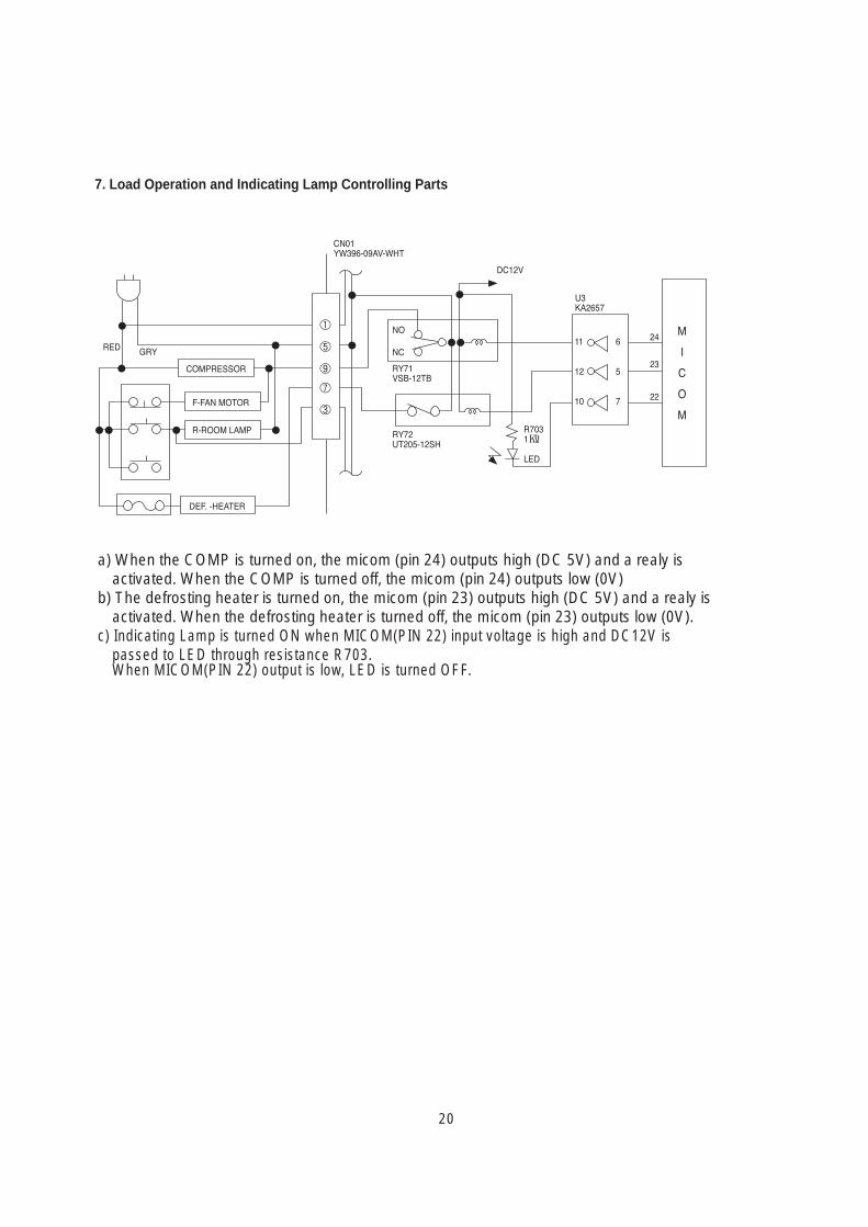
a) When the COMP is turned on, the micom (pin 24) outputs high (DC 5V) and a realy isactivated. When the COMP is turned off, the micom (pin 24) outputs low (0V)
b) The defrosting heater is turned on, the micom (pin 23) outputs high (DC 5V) and a realy isactivated. When the defrosting heater is turned off, the micom (pin 23) outputs low (0V).
c) Indicating Lamp is turned ON when MICOM(PIN 22) input voltage is high and DC12V ispassed to LED through resistance R703.When MICOM(PIN 22) output is low, LED is turned OFF.
7. Load Operation and Indicating Lamp Controlling Parts
21
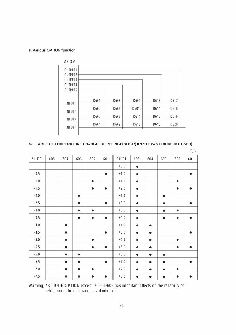
8. Various OPTION function
8-1. TABLE OF TEMPERATURE CHANGE OF REFRIGERATOR(:RELEVANT DIODE NO. USED)
()
D601
D602
D603
D604
D605
D606
D607
D608
D609
D6010
D611
D612
D613
D614
D615
D616
D617
D618
D619
D620
MICOM
OUTPUT1
INPUT1
INPUT2
INPUT3
INPUT4
OUTPUT2OUTPUT3OUTPUT4OUTPUT5
-0.5
-1.0
-1.5
-2.0
-2.5
-3.0
-3.5
-4.0
-4.5
-5.0
-5.5
-6.0
-6.5
-7.0
-7.5
+0.5
+1.0
+1.5
+2.0
+2.5
+3.0
+3.5
+4.0
+4.5
+5.0
+5.5
+6.0
+6.5
+7.0
+7.5
+8.0
605 604 603 602 601 605 604 603 602 601SHIFT SHIFT
Warning) As DIODE OPTION except D601-D605 has important effects on the reliability ofrefrigerator, do not change it voluntarily!!!
22
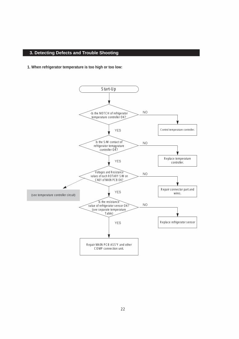
1. When refrigerator temperature is too high or too low:
3. Detecting Defects and Trouble Shooting
Start-Up
-Is the NOTCH of refrigerator temperature controller OK?
Is the S/W contact of refrigerator temperature
controller OK?
Voltages and Resistance values of each ROTARY S/W on
CN01 of MAIN PCB OK?
Is the resistance value of refrigerator sensor OK?
(see separate temperature Table)
Control temperature controller.
(see temperature controller circuit)
Repair MAIN PCB ASS'Y and other COMP connection unit.
NO
Replace temperaturecontroller.
NO
Repair connector part andwires.
NO
Replace refrigerator sensor
NO
YES
YES
YES
YES
Y
23
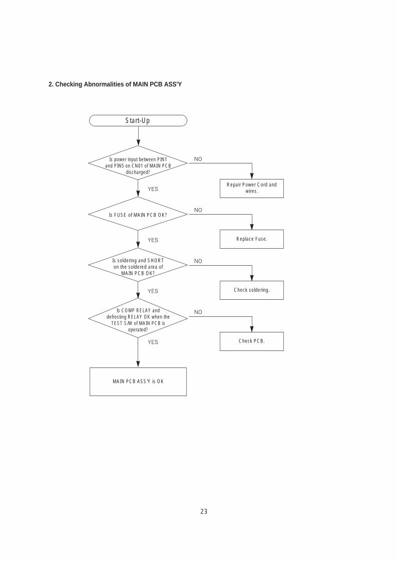
2. Checking Abnormalities of MAIN PCB ASS'Y
Start-Up
Is power input between PIN1 and PIN5 on CN01 of MAIN PCB
discharged?
Is FUSE of MAIN PCB OK?
Is soldering and SHORT on the soldered area of
MAIN PCB OK?
Is COMP RELAY and defrosting RELAY OK when the
TEST S/W of MAIN PCB is operated?
Repair Power Cord andwires.
MAIN PCB ASS'Y is OK
NO
Replace Fuse.
NO
Check soldering.
NO
Check PCB.
NO
YES
YES
YES
YES
24
4. Circuit
25
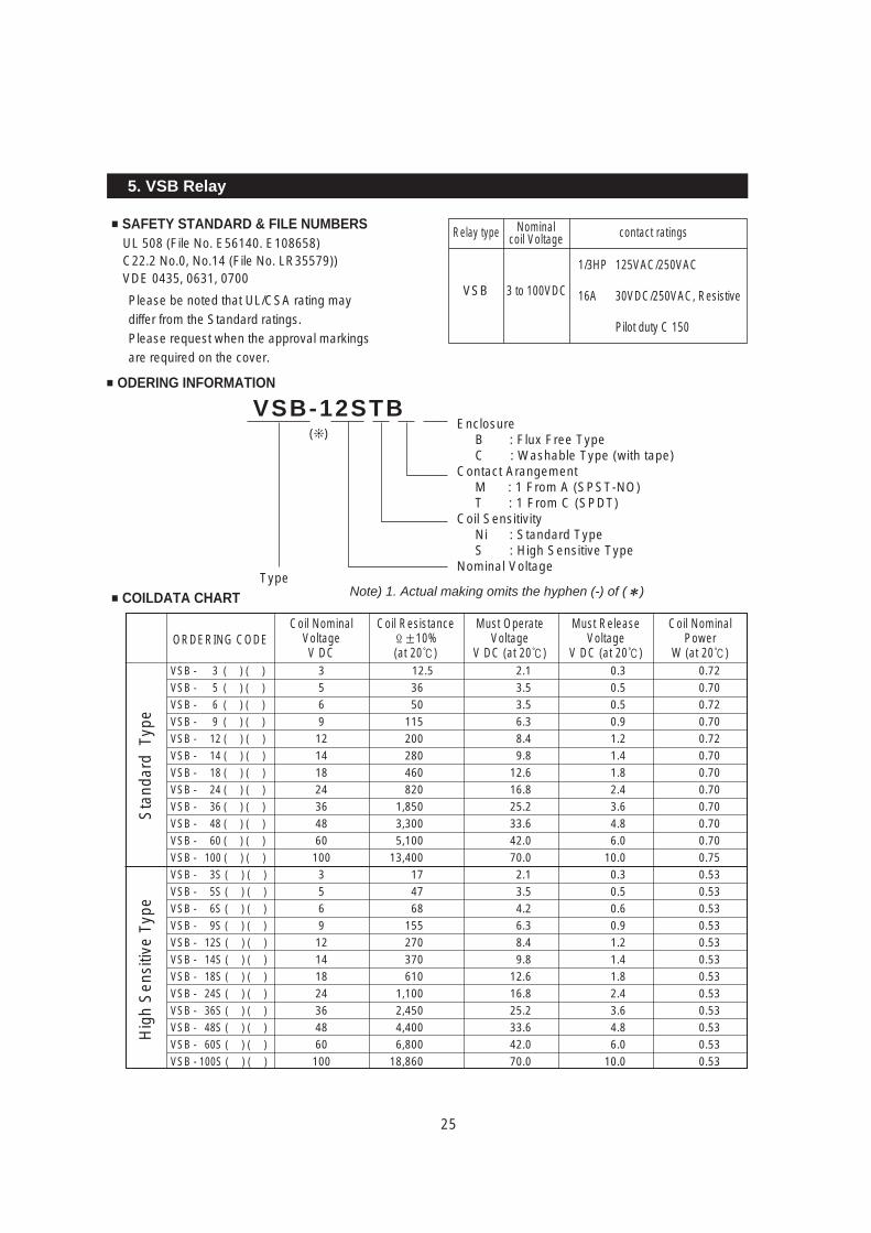
SAFETY STANDARD & FILE NUMBERSUL 508 (File No. E56140. E108658)C22.2 No.0, No.14 (File No. LR35579))VDE 0435, 0631, 0700
Please be noted that UL/CSA rating may differ from the Standard ratings.Please request when the approval markings are required on the cover.
ODERING INFORMATION
COILDATA CHART
VSB-12STB
Type
EnclosureB : Flux Free TypeC : Washable Type (with tape)
Contact ArangementM : 1 From A (SPST-NO)T : 1 From C (SPDT)
Coil SensitivityNi : Standard TypeS : High Sensitive Type
Nominal Voltage
Note) 1. Actual making omits the hyphen (-) of ( )
5. VSB Relay
Relay type contact ratingsNominalcoil Voltage
VSB 3 to 100VDC
1/3HP
16A
125VAC/250VAC
30VDC/250VAC, Resistive
Pilot duty C 150
VSB - 3 ( ) ( )
VSB - 5 ( ) ( )
VSB - 6 ( ) ( )
VSB - 9 ( ) ( )
VSB - 12 ( ) ( )
VSB - 14 ( ) ( )
VSB - 18 ( ) ( )
VSB - 24 ( ) ( )
VSB - 36 ( ) ( )
VSB - 48 ( ) ( )
VSB - 60 ( ) ( )
VSB - 100 ( ) ( )
VSB - 3S ( ) ( )
VSB - 5S ( ) ( )
VSB - 6S ( ) ( )
VSB - 9S ( ) ( )
VSB - 12S ( ) ( )
VSB - 14S ( ) ( )
VSB - 18S ( ) ( )
VSB - 24S ( ) ( )
VSB - 36S ( ) ( )
VSB - 48S ( ) ( )
VSB - 60S ( ) ( )
VSB - 100S ( ) ( )
3
5
6
9
12
14
18
24
36
48
60
100
3
5
6
9
12
14
18
24
36
48
60
100
36
50
115
200
280
460
820
1,850
3,300
5,100
13,400
17
47
68
155
270
370
610
1,100
2,450
4,400
6,800
18,860
2.1
3.5
3.5
6.3
8.4
9.8
12.6
16.8
25.2
33.6
42.0
70.0
2.1
3.5
4.2
6.3
8.4
9.8
12.6
16.8
25.2
33.6
42.0
70.0
0.3
0.5
0.5
0.9
1.2
1.4
1.8
2.4
3.6
4.8
6.0
10.0
0.3
0.5
0.6
0.9
1.2
1.4
1.8
2.4
3.6
4.8
6.0
10.0
0.72
0.70
0.72
0.70
0.72
0.70
0.70
0.70
0.70
0.70
0.70
0.75
0.53
0.53
0.53
0.53
0.53
0.53
0.53
0.53
0.53
0.53
0.53
0.53
12.5
Sta
ndar
d T
ype
Hig
h S
ensi
tive
Type
ORDERING CODECoil Nominal
VoltageV DC
Coil ResistanceΩ±10%(at 20)
Must OperateVoltage
V DC (at 20)
Must ReleaseVoltage
V DC (at 20)
Coil NominalPower
W (at 20)
()
26
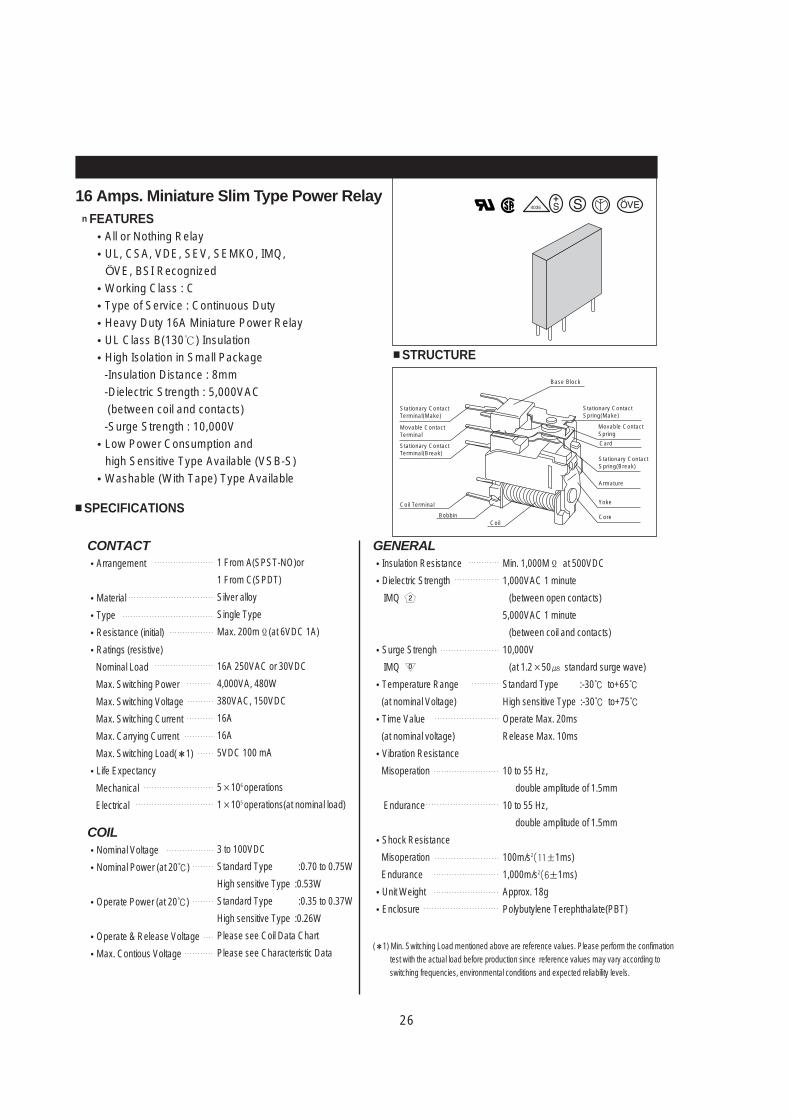
n FEATURESAll or Nothing RelayUL, CSA, VDE, SEV, SEMKO, IMQ, ÖVE, BSI RecognizedWorking Class : CType of Service : Continuous DutyHeavy Duty 16A Miniature Power RelayUL Class B(130) InsulationHigh Isolation in Small Package -Insulation Distance : 8mm-Dielectric Strength : 5,000VAC(between coil and contacts)-Surge Strength : 10,000VLow Power Consumption and high Sensitive Type Available (VSB-S)Washable (With Tape) Type Available
SPECIFICATIONS
CONTACTArrangement
Material
Type
Resistance (initial)
Ratings (resistive)
Nominal Load
Max. Switching Power
Max. Switching Voltage
Max. Switching Current
Max. Carrying Current
Max. Switching Load( 1)
Life Expectancy
Mechanical
Electrical
1 From A(SPST-NO)or
1 From C(SPDT)
Silver alloy
Single Type
Max. 200mΩ(at 6VDC 1A)
16A 250VAC or 30VDC
4,000VA, 480W
380VAC, 150VDC
16A
16A
5VDC 100 mA
5×10⁶ operations
1×10⁵ operations(at nominal load)
COILNominal Voltage
Nominal Power (at 20)
Operate Power (at 20)
Operate & Release Voltage
Max. Contious Voltage
3 to 100VDC
Standard Type :0.70 to 0.75W
High sensitive Type :0.53W
Standard Type :0.35 to 0.37W
High sensitive Type :0.26W
Please see Coil Data Chart
Please see Characteristic Data
STRUCTURE
16 Amps. Miniature Slim Type Power Relay
Stationary ContactTerminal(Make)
Stationary ContactSpring(Make)
Stationary ContactSpring(Break)
Armature
Yoke
Core
Movable ContactSpring
Card
Base Block
Stationary ContactTerminal(Break)
Coil Terminal
BobbinCoil
Movable ContactTerminal
GENERALInsulation Resistance
Dielectric Strength
IMQ
Surge Strengh
IMQ
Temperature Range
(at nominal Voltage)
Time Value
(at nominal voltage)
Vibration Resistance
Misoperation
Endurance
Shock Resistance
Misoperation
Endurance
Unit Weight
Enclosure
( 1) Min. Switching Load mentioned above are reference values. Please perform the confimationtest with the actual load before production since reference values may vary according toswitching frequencies, environmental conditions and expected reliability levels.
Min. 1,000MΩ at 500VDC
1,000VAC 1 minute
(between open contacts)
5,000VAC 1 minute
(between coil and contacts)
10,000V
(at 1.2×50 standard surge wave)
Standard Type :-30 to+65
High sensitive Type :-30 to+75
Operate Max. 20ms
Release Max. 10ms
10 to 55 Hz,
double amplitude of 1.5mm
10 to 55 Hz,
double amplitude of 1.5mm
100m/s2(11±1ms)
1,000m/s2(6±1ms)
Approx. 18g
Polybutylene Terephthalate(PBT)
27
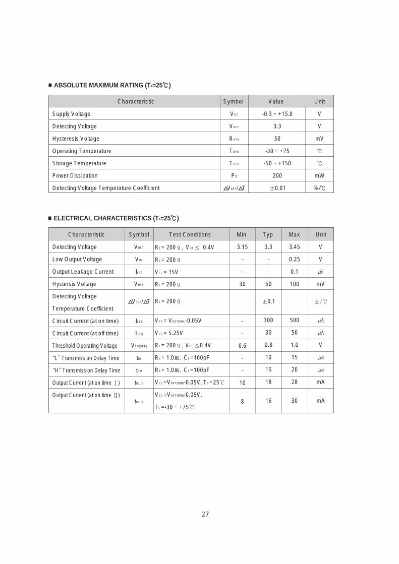
ABSOLUTE MAXIMUM RATING (TA=25)
VCC
VDET
RHYS
TOPR
TSTG
PD
VDET/ T
V
V
mV
mW
%/
-0.3 ~ +15.0
3.3
50
-30 ~ +75
-50 ~ +150
200
±0.01
ELECTRICAL CHARACTERISTICS (TA=25)
Detecting Voltage
Low Output Voltage
Output Leakage Current
Hystersis Voltage
Detecting Voltage
Temperature Coefficient
Circuit Current (at on time)
Circuit Current (at off time)
Threshold Operating Voltage
“L”Transmission Delay Time
“H”Transmission Delay Time
Output Current (at on time Ⅰ)
Output Current (at on time Ⅱ)
VDET
VOL
ILKG
VHYS
VDET/ T
ICCL
ICCH
VTH(OPR)
tDL
tDM
tOL Ⅰ
tOL Ⅱ
3.15
-
-
30
-
-
0.6
-
-
10
8
3.3
-
-
50
±0.1
300
30
0.8
10
15
18
16
3.45
0.25
0.1
100
500
50
1.0
15
20
28
30
V
V
mV
±/
V
mA
mA
RL = 200Ω, VOL ≤ 0.4V
RL = 200Ω
VCC = 15V
RL = 200Ω
RL = 200Ω
VCC = VDET(MIN)-0.05V
VCC = 5.25V
RL = 200Ω, VOL ≤0.4V
RL = 1.0, CL =100pF
RL = 1.0, CL =100pF
VCC =VDET(MIN)-0.05V, TC =25
VCC =VDET(MIN)-0.05V,
TC =-30 ~ +75
Symbol Test Conditions
Characteristic Symbol Value Unit
Characteristic
Supply Voltage
Detecting Voltage
Hysteresis Voltage
Operating Temperature
Storage Temperature
Power Dissipation
Detecting Voltage Temperature Coefficient
Min Typ Max Unit
28
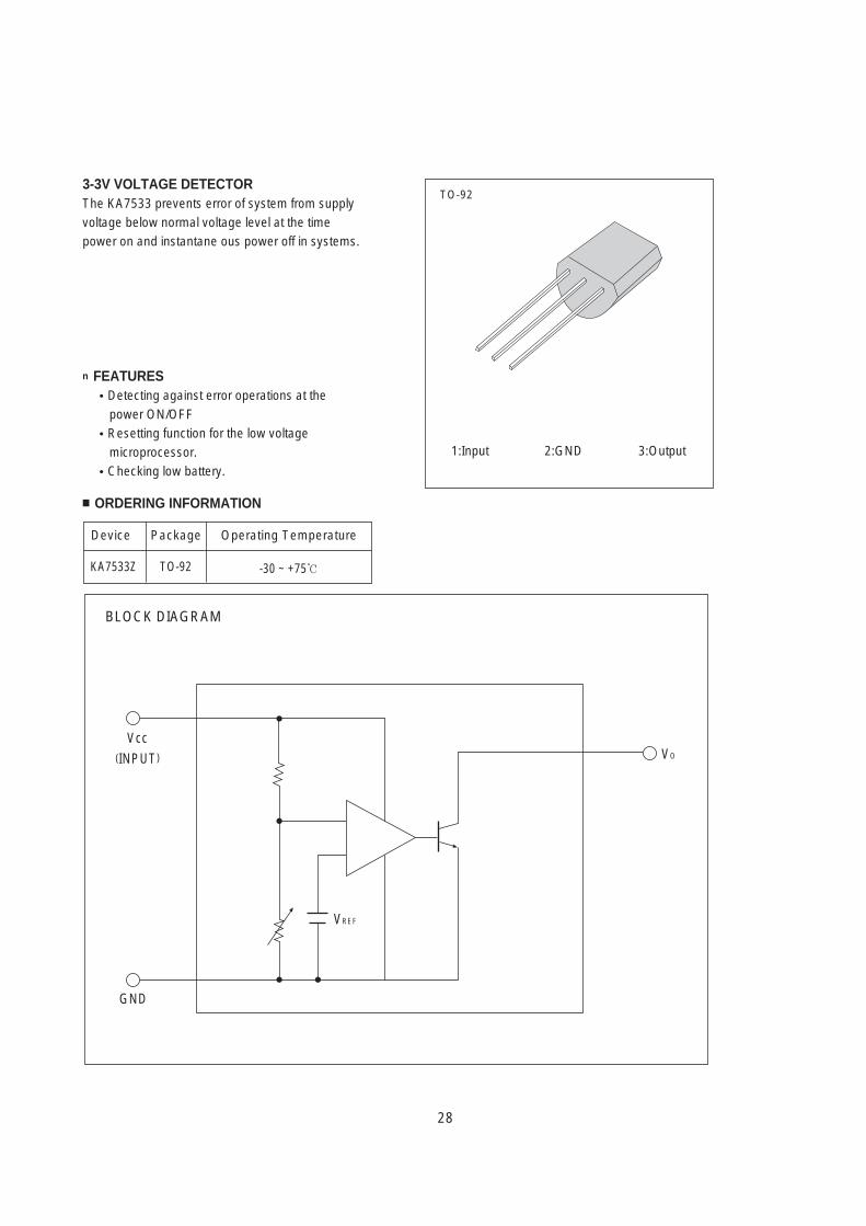
3-3V VOLTAGE DETECTORThe KA7533 prevents error of system from supplyvoltage below normal voltage level at the timepower on and instantane ous power off in systems.
n FEATURESDetecting against error operations at thepower ON/OFFResetting function for the low voltagemicroprocessor.Checking low battery.
ORDERING INFORMATION
BLOCK DIAGRAM
Vcc(INPUT)
GND
VREF
VO
TO-92
1:Input 2:GND 3:Output
Device Package Operating Temperature
KA7533Z TO-92 -30 ~ +75
29
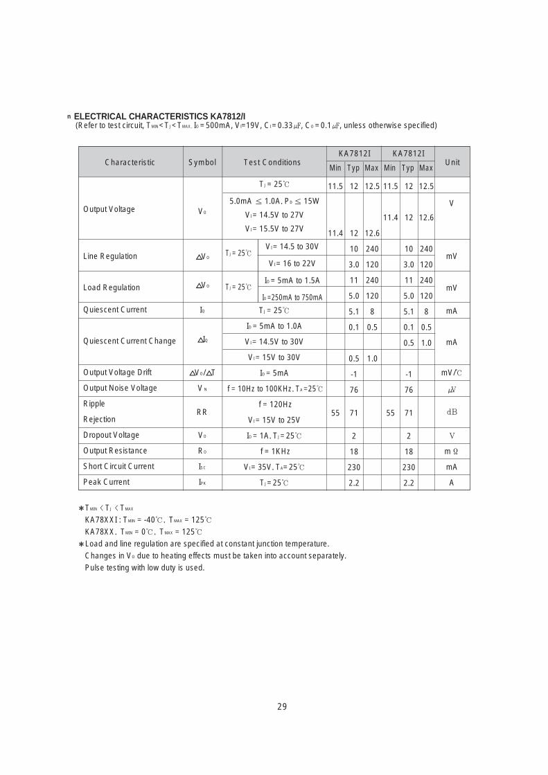
n ELECTRICAL CHARACTERISTICS KA7812/I(Refer to test circuit, TMIN<TJ<TMAX, IO =500mA, VI=19V, CI =0.33, CO =0.1, unless otherwise specified)
VO
VO
VO
IQ
IQ
VO/ T
VN
RR
VO
RO
ISC
IPK
TJ = 25
5.0mA ≤ 1.0A, PD ≤ 15W
VI = 14.5V to 27V
VI = 15.5V to 27V
11.5
11.4
55
12
12
10
3.0
11
5.0
5.1
0.1
0.5
-1
76
71
2
18
230
2.2
12.5
12.6
240
120
240
120
8
0.5
1.0
11.5
11.4
55
12
12
10
3.0
11
5.0
5.1
0.1
0.5
-1
76
71
2
18
230
2.2
12.5
12.6
240
120
240
120
8
0.5
1.0
V
mV
mV
mA
mA
mV/
dB
V
mΩ
mA
A
TJ = 25
IO = 5mA to 1.0A
VI = 14.5V to 30V
VI = 15V to 30V
IO = 5mA
f = 10Hz to 100KHz, TA =25
f = 120Hz
VI = 15V to 25V
IO = 1A, TJ=25
f = 1KHz
VI = 35V, TA=25
TJ=25
TJ = 25
TJ = 25
VI = 14.5 to 30V
VI = 16 to 22V
IO = 5mA to 1.5A
IO =250mA to 750mA
Characteristic Symbol Test ConditionsKA7812I KA7812I
Unit
Output Voltage
Line Regulation
Load Regulation
Quiescent Current
Quiescent Current Change
Output Voltage Drift
Output Noise Voltage
Ripple
Rejection
Dropout Voltage
Output Resistance
Short Circuit Current
Peak Current
TMIN TJ TMAX
KA78XXI : TMIN = -40, TMAX = 125KA78XX, TMIN = 0, TMAX = 125Load and line regulation are specified at constant junction temperature. Changes in VO due to heating effects must be taken into account separately.Pulse testing with low duty is used.
Min Typ Max Min Typ Max
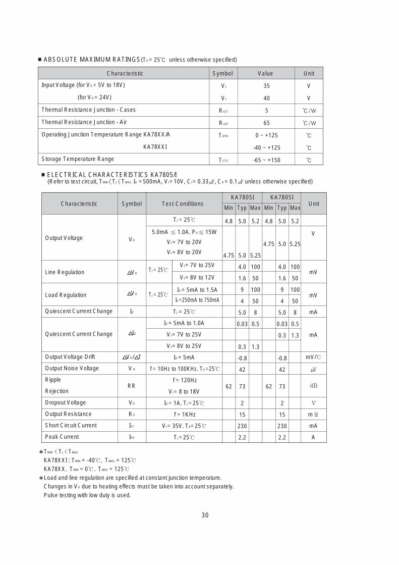
ELECTRICAL CHARACTERISTICS KA7805/I(Refer to test circuit, TMIN<TJ<TMAX, IO =500mA, VI =10V, CI = 0.33, CO = 0.1 unless otherwise specified)
VO
VO
VO
IQ
IQ
VO/ T
VN
RR
VO
RO
ISC
IPK
V
mV
mV
mA
mA
mV/
dB
V
mΩ
mA
A
TJ = 25
TJ = 25
Characteristic Symbol Test ConditionsKA7805I KA7805I
UnitMin Typ Max Min Typ Max
Output Voltage
Line Regulation
Load Regulation
Quiescent Current Change
Quiescent Current Change
Output Voltage Drift
Output Noise Voltage
Ripple
Rejection
Dropout Voltage
Output Resistance
Short Circuit Current
Peak Current
TMIN TJ TMAX
KA78XXI : TMIN = -40, TMAX = 125KA78XX, TMIN = 0, TMAX = 125Load and line regulation are specified at constant junction temperature. Changes in VO due to heating effects must be taken into account separately.Pulse testing with low duty is used.
ABSOLUTE MAXIMUM RATINGS(TA = 25 unless otherwise specified)
VI
VI
ReJC
ReJA
TOPR
TSTG
V
V
/W
/W
35
40
5
65
0 ~ +125
-40 ~ +125
-65 ~ +150
Characteristic Symbol Value Unit
Input Voltage (for VO = 5V to 18V)
(for VO = 24V)
Thermal Resistance Junction - Cases
Thermal Resistance Junction - Air
Operating Junction Temperature Range KA78XX/A
KA78XXI
Storage Temperature Range
TJ = 25
5.0mA ≤ 1.0A, PO≤ 15W
VI = 7V to 20V
VI = 8V to 20V
VI = 7V to 25V
VI = 8V to 12V
IO = 5mA to 1.5A
IO =250mA to 750mA
TJ = 25
IO = 5mA to 1.0A
VI = 7V to 25V
VI = 8V to 25V
IO = 5mA
f = 10Hz to 100KHz, TA =25
f = 120Hz
VI = 8 to 18V
IO = 1A, TJ=25
f = 1KHz
VI = 35V, TA=25
TJ=25
4.8
4.75
62
5.0
5.0
4.0
1.6
9
4
5.0
0.03
0.3
-0.8
42
73
2
15
230
2.2
5.2
5.25
100
50
100
50
8
0.5
1.3
4.8
4.75
62
5.0
5.0
4.0
1.6
9
4
5.0
0.03
0.3
-0.8
42
73
2
15
230
2.2
5.2
5.25
100
50
100
50
8
0.5
1.3
30
31
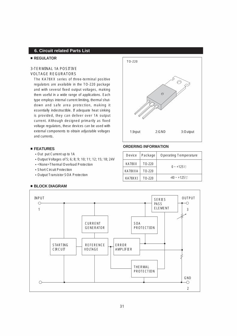
6. Circuit related Parts List
3-TERMINAL 1A POSITIVE VOLTAGE REGURATORS
The KA78XX series of three-terminal positiveregulators are available in the TO-220 packageand with several fixed output voltages, makingthem useful in a wide range of applications. Eachtype employs internal current limiting, thermal shut-down and safe area protection, making itessentially indestructible. If adequate heat sinkingis provided, they can deliver over 1A outputcurrent. Although designed primarily as fixedvoltage regulators, these devices can be used withexternal components to obtain adjustable voltagesand currents.
FEATURESOut put Current up to 1AOutput Voltages of 5; 6; 8; 9; 10; 11; 12; 15; 18; 24V<None>Thermal Overload ProtectionShort Circuit ProtectionOutput Transistor SOA Protection
BLOCK DIAGRAM
REGULATOR
ORDERING INFORMATION
1
INPUT OUTPUT
3
GND
2
CURRENTGENERATOR
SOAPROTECTION
SERIESPASSELEMENT
REFERENCEVOLTAGE
STARTINGCIRCUIT
ERRORAMPLIFIER
THERMALPROTECTION
TO-220
1:Input 2:GND 3:Output
Device Package Operating Temperature
KA78XX
KA78XXA
KA78XXI
TO-220
TO-220
TO-220
0 ~ +125
-40 ~ +125
32
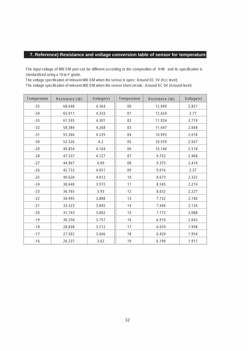
The input voltage of MICOM port can be different according to the composition of H/W and its specification isstandardized using a 10-F grade.The voltage specification of relevant MICOM when the sensor is open : Around DC 5V (Vcc level)The voltage specification of relevant MICOM when the sensor short circuits : Around DC 0V (Ground level)
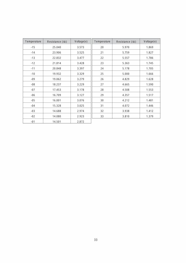
7. Reference) Resistance and voltage conversion table of sensor for temperature
-35
-34
-33
-32
-31
-30
-29
-28
-27
-26
-25
-24
-23
-22
-21
-20
-19
-18
-17
-16
68.648
65.011
61.595
58.384
55.366
52.526
49.854
47.337
44.967
42.733
40.626
38.640
36.765
34.995
33.323
31.743
30.250
28.838
27.502
26.237
4.364
4.333
4.301
4.268
4.235
4.2
4.164
4.127
4.09
4.051
4.012
3.972
3.93
3.888
3.845
3.802
3.757
3.712
3.666
3.62
Temperature Resistance () Voltage(v)
00
01
02
03
04
05
06
07
08
09
10
11
12
13
14
15
16
17
18
19
12.949
12.424
11.924
11.447
10.993
10.559
10.146
9.752
9.375
9.016
8.673
8.345
8.032
7.732
7.446
7.172
6.910
6.659
6.420
6.190
2.821
2.77
2.719
2.668
2.618
2.567
2.518
2.468
2.419
2.37
2.322
2.274
2.227
2.180
2.134
2.088
2.043
1.998
1.954
1.911
Temperature Resistance () Voltage(v)
33
-15
-14
-13
-12
-11
-10
-09
-08
-07
-06
-05
-04
-03
-02
-01
25.040
23.906
22.832
21.814
20.848
19.932
19.062
18.237
17.453
16.709
16.001
15.328
14.688
14.080
14.501
3.573
3.525
3.477
3.428
3.397
3.329
3.279
3.229
3.178
3.127
3.076
3.025
2.974
2.923
2.872
Temperature Resistance () Voltage(v)
20
21
22
23
24
25
26
27
28
29
30
31
32
33
5.970
5.759
5.557
5.363
5.178
5.000
4.829
4.665
4.508
4.357
4.212
4.072
3.938
3.810
1.869
1.827
1.786
1.745
1.705
1.666
1.628
1.590
1.553
1.517
1.481
1.446
1.412
1.379
Temperature Resistance () Voltage(v)
34
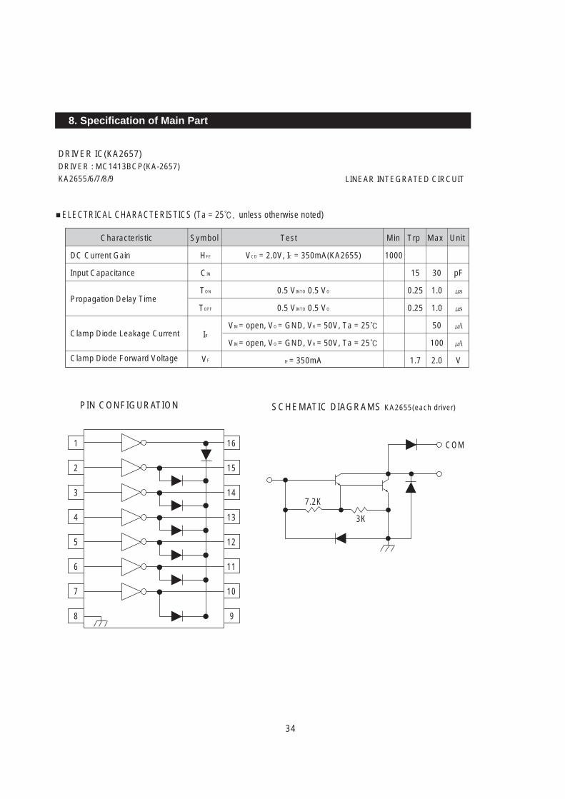
DRIVER IC(KA2657)DRIVER : MC1413BCP(KA-2657)KA2655/6/7/8/9 LINEAR INTEGRATED CIRCUIT
8. Specification of Main Part
ELECTRICAL CHARACTERISTICS (Ta = 25, unless otherwise noted)
HFE
CIN
TON
TOFF
IR
VF
pF
V
VCD = 2.0V, IC = 350mA(KA2655)
0.5 VINTO 0.5 VO
0.5 VINTO 0.5 VO
VIN = open, VO = GND, VR = 50V, Ta = 25
VIN = open, VO = GND, VR = 50V, Ta = 25
IF = 350mA
1000
15
0.25
0.25
1.7
30
1.0
1.0
50
100
2.0
Characteristic Symbol Test
DC Current Gain
Input Capacitance
Propagation Delay Time
Clamp Diode Leakage Current
Clamp Diode Forward Voltage
1
2
3
4
5
6
7
8
16
PIN CONFIGURATION
15
14
13
12
11
10
9
SCHEMATIC DIAGRAMS KA2655(each driver)
7.2K
3K
COM
Min Trp Max Unit
35
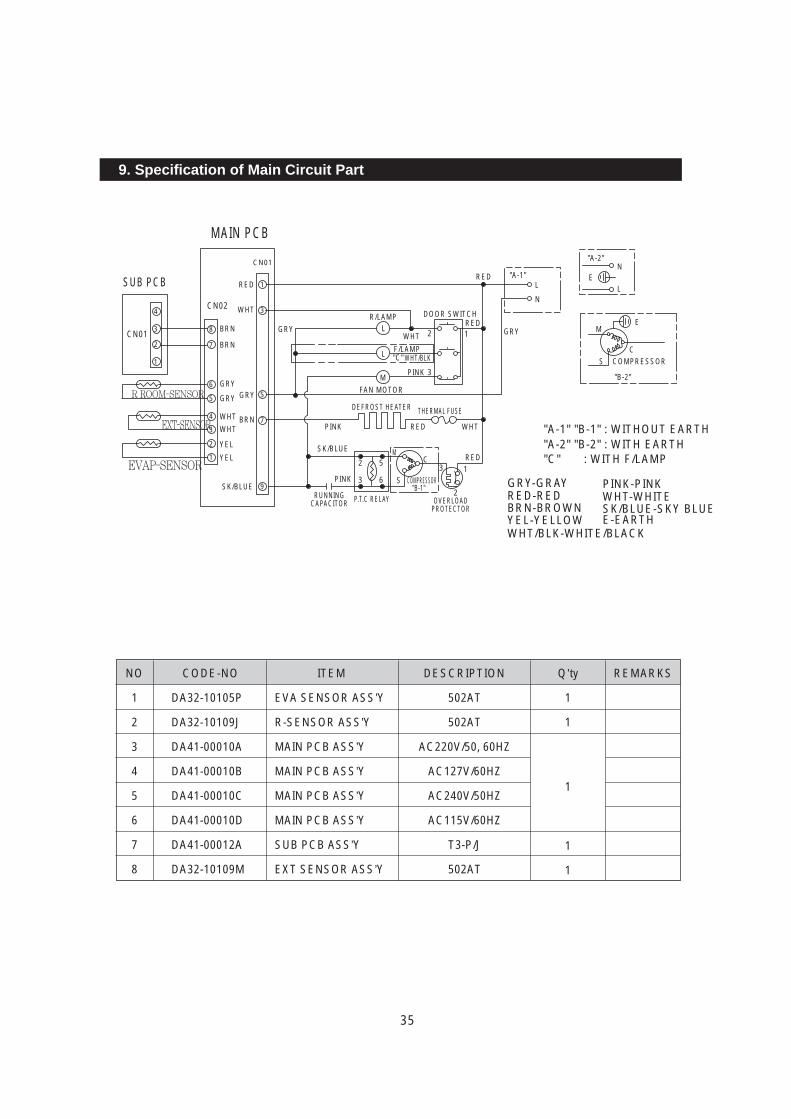
9. Specification of Main Circuit Part
4
8
1
3
7
6
5
4
3
2
1
3
2
1
CN01
CN02
CN01
RED
BRN
BRN
GRY
GRY
YEL
YEL
WHT
RED
RED
WHTREDPINK
REDC
S
M
M
SC
E
N
L
NL
E
"A-2"
"A-1"
COMPRESSOR GRY-GRAYRED-REDBRN-BROWNYEL-YELLOWWHT/BLK-WHITE/BLACK
PINK-PINK
COMPRESSOR
"B-2"
"A-2" "B-2" : WITH EARTH"A-1" "B-1" : WITHOUT EARTH
"C" : WITH F/LAMP
WHT-WHITESK/BLUE-SKY BLUEE-EARTH
GRYWHT
F/LAMPWHT/BLK
PINK
FAN MOTOR
DEFROST HEATER THERMAL FUSE
SK/BLUE
PINK
2
3
1
1
2
2 5
3 6
"C"
"B-1"
3
GRY
R/LAMP DOOR SWITCH
GRY
BRN
SK/BLUE
SUB PCB
R ROOM-SENSOR
EVAP-SENSOR
MAIN PCB
WHT
WHTEXT-SENSOR
L
L
M
RUNNINGCAPACITOR OVERLOAD
PROTECTORP.T.C RELAY
5
9
7
NO CODE-NO ITEM DESCRIPTION Q’ty
DA32-10105P
DA32-10109J
DA41-00010A
DA41-00010B
DA41-00010C
DA41-00010D
DA41-00012A
DA32-10109M
EVA SENSOR ASS’Y
R-SENSOR ASS’Y
MAIN PCB ASS’Y
MAIN PCB ASS’Y
MAIN PCB ASS’Y
MAIN PCB ASS’Y
SUB PCB ASS’Y
EXT SENSOR ASS’Y
502AT
502AT
AC220V/50, 60HZ
AC127V/60HZ
AC240V/50HZ
AC115V/60HZ
T3-P/J
502AT
1
1
1
1
1
1
2
3
4
5
6
7
8
REMARKS
36
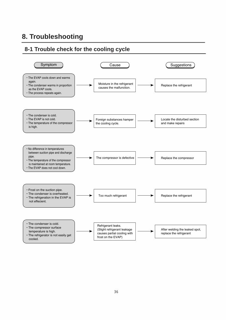
8-1 Trouble check for the cooling cycle
8. Troubleshooting
37
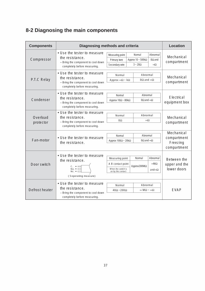
8-2 Diagnosing the main components
Components
Compressor
• Use the tester to measurethe resistance.– Bring the component to cool down
completely before measuring.
P.T.C Relay
Condenser
Overloadprotector
Fan-motor
Door switch
Defrost heater
Diagnosing methods and criteria Location
Measuring point
Primary iwre
Secondary wire
Normal
Approx 10 ~ 500kΩ
3 ~ 20Ω
Abnormal
0Ω and
∞Ω
• Use the tester to measurethe resistance.– Bring the component to cool down
completely before measuring.
Normal
Approx ∞Ω ~ kΩ
Abnormal
0Ω and ∞Ω
Normal
Approx 10Ω ~ 80kΩ
Abnormal
0Ω and ∞Ω
Normal
0Ω
Abnormal
∞Ω
Normal
Approx 100Ω ~ 20kΩ
Abnormal
0Ω and ∞Ω
• Use the tester to measurethe resistance.– Bring the component to cool down
completely before measuring.
• Use the tester to measurethe resistance.– Bring the component to cool down
completely before measuring.
• Use the tester to measurethe resistance.
• Use the tester to measurethe resistance.
Measuring point
A B contact point
When the switch ison by the contact
and∞Ω
Normal
Approx200MΩ
Abnormal
∞MΩ
• Use the tester to measurethe resistance.– Bring the component to cool down
completely before measuring.
Mechanicalcompartment
Mechanicalcompartment
Electricalequipment box
Mechanicalcompartment
Mechanicalcompartment
Freezingcompartment
Between theupper and thelower doors
EVAPNormal
40Ω ~200Ω
Abnormal
∞ MΩ ~ ∞Ω
C.No.Nc.
( Seperating measure)
38
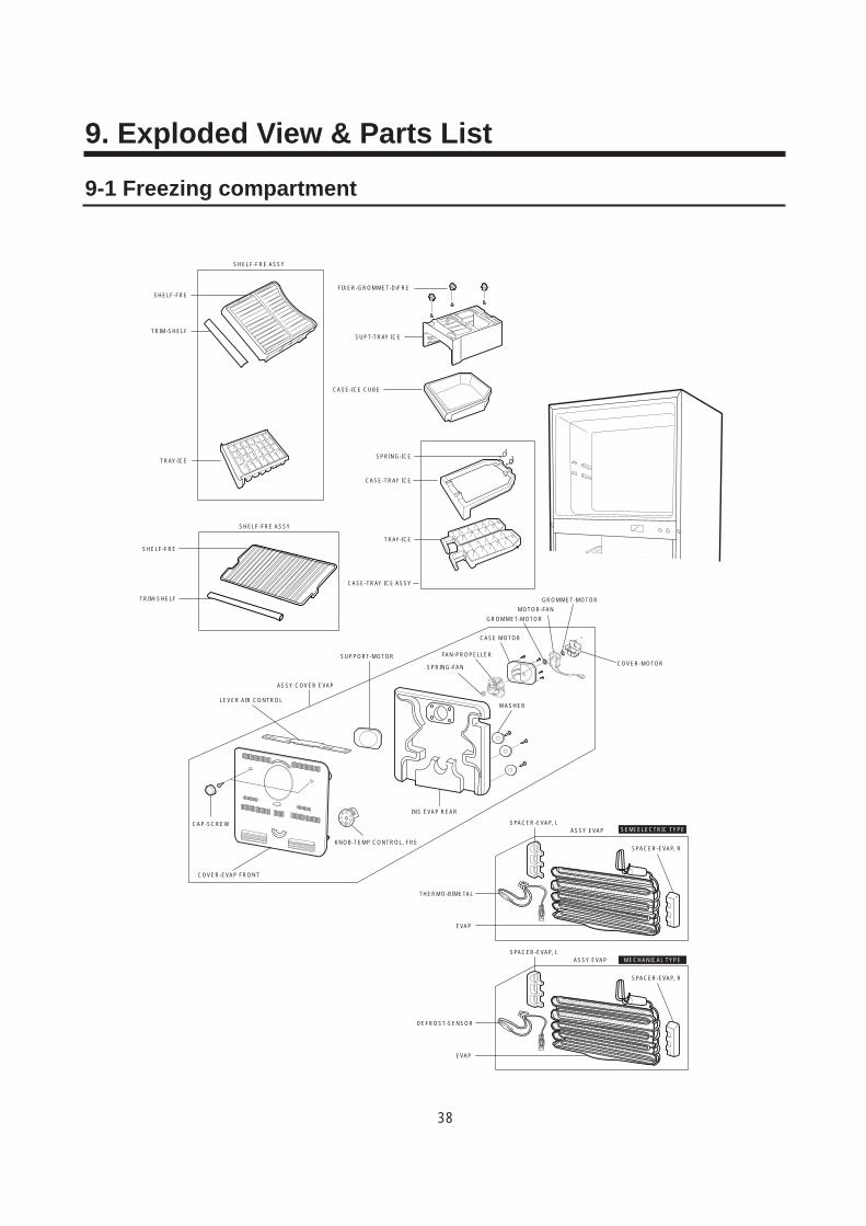
9-1 Freezing compartment
9. Exploded View & Parts List
SHELF-FRE ASSY
SHELF-FREFIXER-GROMMET-D/FRE
SUPT-TRAY ICE
CASE-ICE CUBE
SPRING-ICE
CASE-TRAY ICE
SHELF-FRE ASSY
SHELF-FRE
TRIM-SHELF
TRAY-ICE
CASE-TRAY ICE ASSY
CAP-SCREW
COVER-EVAP FRONT
KNOB-TEMP CONTROL, FRE
WASHER
THERMO-BIMETAL
EVAP
ASSY EVAPSPACER-EVAP, L
SPRING-FAN
INS EVAP REAR
FAN-PROPELLER
MOTOR-FAN
GROMMET-MOTOR
CASE MOTOR
COVER-MOTOR
GROMMET-MOTOR
ASSY COVER EVAP
SUPPORT-MOTOR
LEVER AIR CONTROL
TRIM-SHELF
TRAY-ICE
SPACER-EVAP, R
DEFROST-SENSOR
EVAP
ASSY EVAPSPACER-EVAP, L
SPACER-EVAP, R
SEMI ELECTRIC TYPE
MECHANICAL TYPE
39
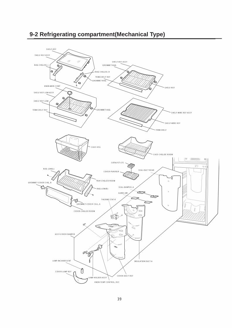
SHELF-REF
SHELF-REF ASSY
RAIL-CHILLED, L
KNOB-MOIS CONT
SHELF-REF LOW ASSY
SHELF-REF LOW
TRIM-SHELF REF
CASE-VEG
RAIL-LOW(L)
GROMMET-COVER CHIL, B
GROMMET-COVER CHLL, A
TRAY-CHILLED ROOM
SEAL-DAMPER, A
SEAL-DUCT REAR
GUIDE-AIR
THERMO STAT-R
COVER-PURIFIER
CATALYST-LTC
CASE-CHILLDE ROOM
TRIM-SHELF
SHELF-WIRE REF
SHELF-WIRE REF ASSY
SHELF-REF
GROMMET-RAIL
GROMMET-RAIL
GROMMET-RAIL
SHELF-REF ASSY
TRIM-SHELF REF
RAIL-CHILLED, R
RAIL-LOW(R)
COVER-CHILLED ROOM
ASSY-COVER DAMPER
LAMP-INCANDESENT
COVER-LAMP REF
LAMP-HOLDER ASSY
KNOB-TEMP CONTROL, REF
COVER-DUCT REF
INSULATION DUCT-A
9-2 Refrigerating compartment(Mechanical Type)

40
SHELF-REF
SHELF-REF ASSY
RAIL-CHILLED, L
KNOB-MOIS CONT
SHELF-REF LOW ASSY
SHELF-REF LOW
TRIM-SHELF REF
CASE-VEG
RAIL-LOW(L)
GROMMET-COVER CHIL, B
GROMMET-COVER CHLL, A
TRAY-CHILLED ROOM
COVER-PURIFIER
CATALYST-LTC
SEAL-DAMPER, A
CASE-CHILLDE ROOM
TRIM-SHELF
SHELF-WIRE REF
SHELF-WIRE REF ASSY
SHELF-REF
GROMMET-RAIL
GROMMET-RAIL
GROMMET-RAIL
SHELF-REF ASSY
TRIM-SHELF REF
RAIL-CHILLED, R
RAIL-LOW(R)
COVER-CHILLED ROOM
ASSY-COVER DAMPER
LAMP-INCANDESENT
COVER-LAMP REF
LAMP-HOLDER ASSY
KNOB-TEMP CONTROL, REF
COVER-DUCT REF
INSULATION DUCT-A
GUIDE-AIR
SEAL DUCT REAR
PBA-PANEL
9-3 Refrigerating compartment(Semi Electric Type)
41
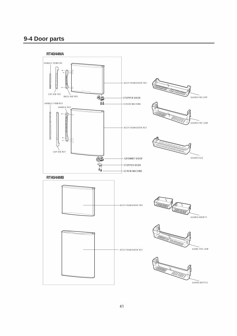
9-4 Door parts
RT40/44MA
RT40/44MB
ASSY-FOAM DOOR FRE
BASE-H/D PRE
HANDLE-REF
CAP-H/D REF
CAP-H/D FRE
HANDLE-TRIM REF
HANDLE-TRIM FRE
SCREW-MACHINE
ASSY-FOAM DOOR REF
ASSY-FOAM DOOR FRE
ASSY-FOAM DOOR REF
GUARD-BOTTLE
GUIDE-FRE LOW
GUARD-VARIETY
GUARD-EGG
GUARD-FRE LOW
GUARD-FRE UPP
GROMMET-DOOR
STOPPER-DOOR
STOPPER-DOOR
SCREW-MACHINE
42
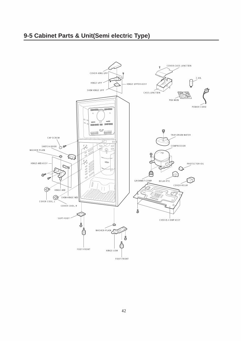
9-5 Cabinet Parts & Unit(Semi electric Type)
COVER-HING UPP
HINGE UPP HINGE UPPER ASSY
SHIM HINGE UPP
SWITCH-DOOR
CAP SCREW
WASHER PLAIN
HINGE-MID ASSY
HINGE-MID
COVER COOL, L
COVER COOL, R
SHIM-HINGE MID
SUPT-FOOT
FOOT-FRONTHINGE-LOW
CHISSIS-COMP ASSY
COVER-RELAY
RELAY-PTCGROMMET-COMP
PROTECTOR-O/L
COMPRESSOR
TRAY-DRAIN WATER
POWER CORD
C-OIL
CASE-JUNCTION
COVER-CASE JUNCTION
PBA MAIN
WASHER-PLAIN
FOOT-FRONT
43
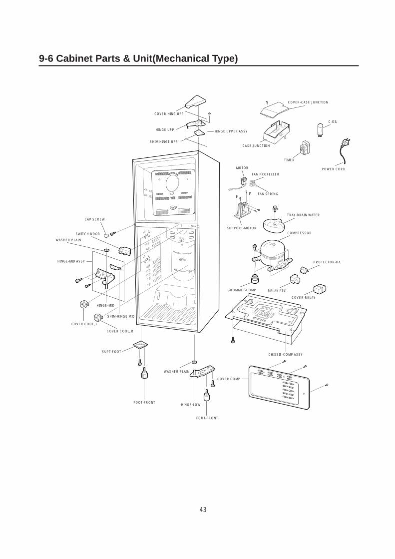
9-6 Cabinet Parts & Unit(Mechanical Type)
COVER-HING UPP
HINGE UPP
SHIM HINGE UPP
SWITCH-DOOR
WASHER PLAIN
HINGE-MID
COVER COOL, L
COVER COOL, R
SHIM-HINGE MID
SUPT-FOOT
FOOT-FRONTHINGE-LOW
CHISSIS-COMP ASSY
COVER-RELAY
RELAY-PTCGROMMET-COMP
PROTECTOR-O/L
COMPRESSOR
TRAY-DRAIN WATER
SUPPORT-MOTOR
MOTOR
FAN PROFELLER
FAN SPRING
POWER CORD
C-OIL
CASE-JUNCTION
COVER-CASE JUNCTION
TIMER
WASHER-PLAIN
FOOT-FRONT
HINGE UPPER ASSY
CAP SCREW
HINGE-MID ASSY
COVER COMP
44
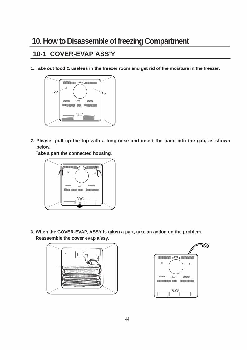
10-1 COVER-EVAP ASS’Y
10. How to Disassemble of freezing Compartment
1. Take out food & useless in the freezer room and get rid of the moisture in the freezer.
2. Please pull up the top with a long-nose and insert the hand into the gab, as shownbelow.Take a part the connected housing.
3. When the COVER-EVAP, ASSY is taken a part, take an action on the problem.Reassemble the cover evap a’ssy.
45
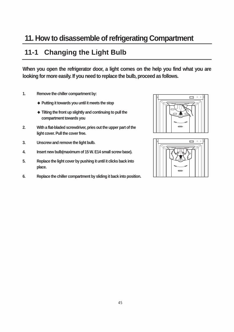
11-1 Changing the Light Bulb
11. How to disassemble of refrigerating Compartment
When you open the refrigerator door, a light comes on the help you find what you arelooking for more easily. If you need to replace the bulb, proceed as follows.
1. Remove the chiller compartment by:
Putting it towards you until it meets the stop
Tilting the front up slightly and continuing to pull thecompartment towards you
2. With a flat-bladed screwdriver, pries out the upper part of thelight cover. Pull the cover free.
3. Unscrew and remove the light bulb.
4. Insert new bulb(maximum of 15 W. E14 small screw base).
5. Replace the light cover by pushing it until it clicks back intoplace.
6. Replace the chiller compartment by sliding it back into position.
ELECTRONICS
Samsung Electronics Co,LtdRefrigerator Division 2003.04Printed in KoreaDA82-00004A
272,Oseon-Dong,Kwangsan-Gu,Kwangju-City,Korea,506-253TEL:(062)950-6811,6812FAX:(062)950-6829