model rl2000 - atm manufacturer · to help ensure proper operation of the atm, ensure the...
TRANSCRIPT

MODEL RL2000AUTOMATED TELLER MACHINE
INSTALLATION MANUAL
TDN 07103-00155 Jan 8, 2013
COPYRIGHT NOTICE© 2013 Triton. All Rights Reserved. TRITON logo is aregistered trademark of Triton Systems of Delaware, LLC.
CORPORATE HEADQUARTERS21405 B St.
Long Beach, MS 39560Phone: (800) 259-6672
Fax: (228) 868-9445

2
MODEL RL2000 INSTALLATION MANUAL
WHAT’S IN THIS INSTALLATION GUIDE
This Installation Guide provides information for the physical installation of the RL2000 ATM. It containsrequirements for site preparation, electrical specifications, and cabinet accessibility that comply with allrelevant codes, laws and regulations. The Installation Guide is divided into the following sections:
� SITE COMPLIANCE. States the customers responsibilities for ensuring all relevant regulations are adheredto for installing ATMs.
� ATM ENVIRONMENTAL PRECAUTIONS CHECKLIST. Describes the general environmental precautionsconsidered when installing the ATM. To help ensure proper operation of the ATM, ensure theenvironmental criteria listed in this checklist are met.
� APPENDIX A. Software License Agreement / Compliance/Emissions statements
� APPENDIX B. ATM Installation for Accessibility guidelines.
� POWER AND COMMUNICATION. Shows cable access area, power requirements, and powering-up the unit.
INTRODUCTION
The Triton RL2000 is a lobby terminal designed for indoor use only. The following sections provide therequirements for installing the RL2000 for your particular site location. To assist you in preparing your site,a check list is provided of various steps that should be carried out prior to the arrival of the ATM.
� TCP/IP OR VSAT CONNECTIVITY. Shows unit cable connectivity for communication protocols TCP/IPand VSAT.
Note: Previously, two (2) cabinet designs were offered - shallow and deep. Only one style cabinet(deep) is now available.
� DIMENSIONS. Describes physical dimensions for the cabinet, control panel components, and signage.
� Physical dimensions.
� Service area dimensions.
� Customer access dimensions
� INSTALLATION. Describes anchoring the cabinet using standard (steel) or the optional chemical anchors.
* NOTICE *
The Model RL2000 ATM supports most models of TDM mechanisms, but starting Apr, 08’, Triton willonly ship the TDM-250 in production units. The SDD, Minimech, and NMD-50 dispensers will continueto be offered. All dispensing mechanisms are shipped installed in the cabinet.

3
MODEL RL2000 INSTALLATION MANUAL
CONTENTS
SITE COMPLIANCE ......................................................................................................... 4
ENVIRONMENTAL PRECAUTIONS ...................................................................................... 5TEMPERATURE / POWER / RF INTERFERENCE REQUIREMENTS ........................................................................ 6
DIMENSIONS ................................................................................................................. 7FRONT VIEW / CUSTOMER ACCESS DIMENSIONS ........................................................................................... 8SERVICE AREA DIMENSIONS ....................................................................................................................... 9DEEP CABINET (BUSINESS HOURS)SIDE VIEWS ............................................................................................................................................. 10MID / HIGH TOPPERS ............................................................................................................................... 11DEEP CABINET (VAULT)SIDE VIEW ......................................................................................................................................... ......12CABINETS ANCHOR “FOOTPRINTS” ....................................................................................................................... 12
CABINET INSTALLATION ................................................................................................. 13TOOLS REQUIRED .................................................................................................................................... 14UNPACKING THE UNIT .............................................................................................................................. 14MARK / DRILL MOUNTING HOLES ............................................................................................................ 16INSTALLING STANDARD ANCHORS / BOLT ATM .......................................................................................... 17INSTALL CHEMICAL ANCHORS / BOLT ATM ............................................................................................... 18
ROUTE POWER / COMMUNICATION CABLES .................................................................. 21ROUTE / CONNECT CABLES ...................................................................................................................... 22TCP/IP CONNECTIVITY ............................................................................................................................. 24VSAT CONNECTIVITY ............................................................................................................................... 25
APPENDIX A - SOFTWARE LICENSE AGREEMENT / COMPLIANCE/EMISSIONS STATEMENTS
APPENDIX B - ATM INSTALLATION FOR ACCESSIBILITY

4
MODEL RL2000 INSTALLATION MANUAL
This document contains the information necessary for the preparation and installation of an RL2000 TritonATM. It’s important that the site complies with the requirements specified in this document. In addition,electrical wiring and mechanical systems must also comply with all relevant laws and regulations.
The site must be prepared by the customer or his agent who is fully conversant with the requirements ofinstalling ATM equipment. The responsibility for ensuring that the site is prepared in compliance with thisdocument remains with the customer.
For information and guidance only, a list is provided in general terms of those matters for which thecustomer is responsible. The list is not intended to be comprehensive and in no way modifies, alters, orlimits the responsibility of the customer for all aspects of adequate site preparation.
1. Location of the equipment and site preparation.2. Site wiring (power, communication).3. Location of other equipment that may cause electrical, electromagnetic or heat induced interfer-
ence.4. Make building alterations to meet wiring and other site requirements.5. Install all communication cables, wall jacks, and associated hardware.6. Provide and install necessary power distribution boxes, conduits, and grounds.7. Ensure all applicable codes, regulations, and laws (electrical, building, safety) are adhered to.8. Ensure the environmental requirements of this unit are met.9. Install the unit at a height which meets the ADA/DDA/CSA accessibility regulations for the state/
country installed.
SITE COMPLIANCE
TSILKCEHCNOITARAPERPETIS
nalproolfangiseddnaetistceleS
temsnoitidnoclatnemnorivneerusnE
seludehcsrodnevdnarotcartnochsilbatsE
stnemeriuqerenilnoitacinummockcehC
sdeenyrosseccanoitallatsninalP
yrassecenekamdnanalproolfkcehCsnoitaretla
stnemeriuqerlacirtcelellatsnI
sdeennoitacinummocrofetiseraperP
)lanoitpo(gniniartrotareponalP
tsetdnasenilnoitacinummocllatsnI
elbaliavaeraseirosseccanoitallatsnierusnE

5
MODEL RL2000 INSTALLATION MANUAL
ENVIRONMENTAL PRECAUTION CHECKLIST

6
MODEL RL2000 INSTALLATION MANUAL
When installing an ATM, some general environmental and power precau-tions need to be considered. Evaluate the location where the ATM will beinstalled. To help ensure proper operation of the ATM, ensure the environ-mental criteria listed in this checklist are met.
TEMPERATURE / HUMIDITY
1. The ATM will operate over a range of tem-peratures and humidity. Generally, these pa-rameters must fall within the followingranges:
� Temperature• 10°C to 40°C• 50°F to 104°F
� Relative Humidity• 20% to 80%• (Non-Condensing)
AC POWER REQUIREMENTS
2. Ensure the following AC power requirementsare met:Current (Max)
• 2.2A @ 115 VRMS at 60 Hz• 1.1A @ 230 VRMS at 50 HzVoltage
��• 90 - 136VRMS @ 50/60 Hz• 198 - 257VRMS @ 50/60 Hz
Power Consumption (Idle)• 0.6A @ 115 VAC at 60 Hz• 0.3A @ 230 VAC at 50 Hz
Power Consumption (Max Load)• 250 Watts @ 120VAC• 250 Watts @ 240VAC
DEDICATED TELEPHONE
3. Ensure the following telephone-line require-ments are met:
Dedicated line. The telephone line servicing the ATMwill not be a “party” line or any other shared typeconnection.Proximity to Interference Sources. Thetelephoneline must not be in close proximity to “noisy” de-vices that could induce interference into the ATMcommunications channel. See the next section foradditional information on “interference sources.”
RF INTERFERENCE
4. Ensure there are no devices near the terminalthat may cause RF interference, such as:� TVs� Coolers� Security devices� Neon signs� Devices with compressors
* IMPORTANT *AC power for the terminal should come from adedicated source with an isolated ground.
Dedicated source. The ATM AC power feed will bea dedicated line, to which no other electrical devicesare connected. The ATM power line will be wired fora single “duplex”-style outlet and connected directlyto the AC service panel.
Isolated Ground. An equipment grounding conduc-tor that is insulated from the conduit or raceway andall other grounding points throughout its entirelength. The only points of electrical connection willbe at the duplex outlet and service panel ends of theline.
Surge ~50A @ 230V

7
MODEL RL2000 INSTALLATION MANUAL
DIMENSIONS
Dimensions listed comply with US Federal ADAGuidelines. For USA installations, check foradditional guidance. For non-USA installations,check regulations relating to the country ofinstall.
Note:Dimensions shown in inches and [millimeters]

8
MODEL RL2000 INSTALLATION MANUAL
PHYSICAL DIMENSIONS
Front View
snoisnemiDsseccAremotsuC
erutaeF thgieH
1 yeKnoitcnuFpoT "54]mm4411[
2 yeK5#)dapyeKniaM(
"63]mm419[
3 redaeRdraC "61/51-83]mm889[
4 retnirPtpieceR "8/5-83)mm289[
5 yarTlliB "61/3-52]mm046[
9
MODEL RL2000 INSTALLATION MANUAL
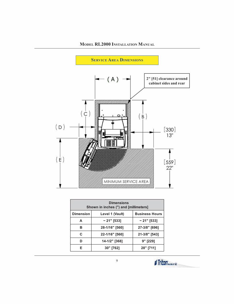
SERVICE AREA DIMENSIONS
snoisnemiD]sretemillim[dna)"(sehcnininwohS
noisnemiD )tluaV(1leveL sruoHssenisuB
A ]335["12~ ]335["12~
B ]065["61/1-82 ]696["8/3-72
C ]065["61/1-22 ]345["8/3-12
D ]863["2/1-41 ]922["9
E ]267["03 ]117["82
2" [51] clearance aroundcabinet sides and rear

10
MODEL RL2000 INSTALLATION MANUAL
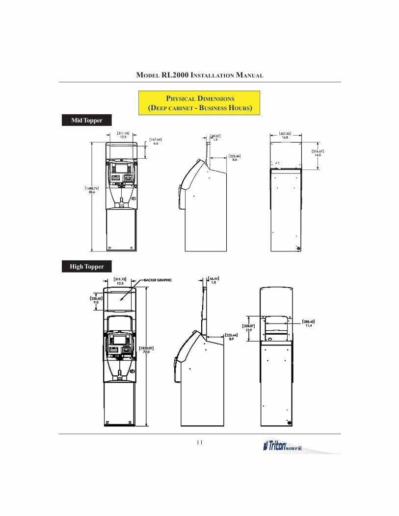
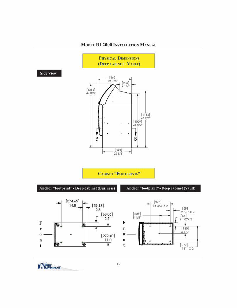
PHYSICAL DIMENSIONS
(DEEP CABINET - BUSINESS HOURS)Side Views
11
MODEL RL2000 INSTALLATION MANUAL
PHYSICAL DIMENSIONS
(DEEP CABINET - BUSINESS HOURS)Mid Topper
High Topper
12
MODEL RL2000 INSTALLATION MANUAL
Anchor “footprint” - Deep cabinet (Business)
CABINET “FOOTPRINTS”
Anchor “footprint” - Deep cabinet (Vault)
Front
Front
PHYSICAL DIMENSIONS
(DEEP CABINET - VAULT)
Side View
13
MODEL RL2000 INSTALLATION MANUAL
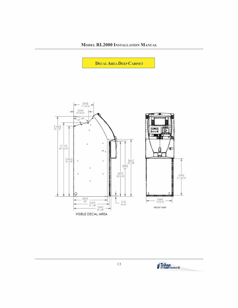
DECAL AREA DEEP CABINET

14
MODEL RL2000 INSTALLATION MANUAL

15
MODEL RL2000 INSTALLATION MANUAL
DECAL AREA VAULT CABINET

16
MODEL RL2000 INSTALLATION MANUAL

17
MODEL RL2000 INSTALLATION MANUAL
CABINET INSTALLATION

18
MODEL RL2000 INSTALLATION MANUAL
CABINET INSTALLATION
The following procedure applies to installing the cabinet assembly using either standard (P/N 06200-00066)or chemical (06200-00060) anchor kits. The anchor kits are not supplied with the unit.
deriuqeRslooT
,sdnuoptoof06tsaeltaotelbatsujda,hcnerweuqroThcnerwtehctarro,hcnerwtnecsercelbatsujda
stniopllirdgnikramrof)tnelaviuqero(hcnupretneC
remmaH tekcos)mm91("4/3 revirdwercstalfegraL
levelelbbuB hcnerwxob/tekcos"61/7 selggogytefaS
noitcetorpgniraeH
,)mm21("2/1,)mm6("4/1-edibrac)mm51("61/9dnata-stibllirdyrnosamdeppit
gnol"6tsael
cirtceleytud-yvaeh"4/3)remmah/yrator(llird
tlebtroppuskcaB renaelcmuucavelbatroP hsurberiW
tiKrohcnAdradnatS
srehsawtalf"2/1epyt-eveels"4/1-4x"2/1
stlobrohcnastun"2/1
tiKrohcnAlacimehC
dnastunxeHsrehsaw
seluspacrohcnalacimehCtniop-lesihcdedaerhT
sdor
1. Carefully inspect the shipping container for any damage and report any damage immediately to theshipping company. Refer to the warranty information in the User or Service manual (as applicable) forinformation about reporting shipping damage.
2. Remove the ATM cabinet from the carton by cutting the straps and removing the top of the box.
3. Remove the packing material from inside of the box.
4. Remove the silver key from the white plastic bag attached to the ATM wrapping.
* IMPORTANT *Model RL2000 ATM is designed for indoor use only!
UNPACK ATM

19
MODEL RL2000 INSTALLATION MANUAL
5. Stand the unit up and walk it out of the shipping carton.
6. Remove the wrapping from the ATM.
7. Use the silver key to unlock both the control panel and thefascia door (which conceals the locking mechanism) on thefront of the cabinet. Open the fascia door.
8. Lift the handle under the bill chute to open the front enclosuredoor. If the door is locked, see the sidebar on this page for helpin unlocking the electronic or mechanical lock, if applicable..
9. Remove the packing material from inside the vault enclosure.
10. The accessory box is shipped inside the cabinet enclosure.Open and inspect the contents. Check the contents against theenclosed packing list and report any missing parts to Triton.
UNLOCKINGCOMBINATION LOCKS
Mechanical Lock. There are twomarks on the dial ring. The indexmark at the top of the dial is usedfor opening the lock. A revolutionis counted each time the selectednumber is aligned with the open-ing index.Locks are shipped on a factory set-ting of ‘50’. To unlock, turn thedial to the left (counterclockwise)FOUR (4) turns, stopping on ‘50’.Then turn the dial to the right(clockwise) until the bolt is re-tracted.
Electronic Lock. The combinationof the lock is preset to 1-2-3-4-5-6. To unlock, enter the preset com-bination and check for proper op-eration. After each keypress, thelock will ‘beep’. After the final digithas been entered, the lock will beeptwice, and the open period begins.When a valid combination hasbeen entered, the operator will haveapproximately 3 seconds to openthe lock. To open the lock, turnthe outer ring of the dial clockwise.After the lock is opened, the vaultdoor may be opened.
**WARNING**DO NOT APPLY POWER TO THIS TER-MINAL UNTIL THE INSTALLATION ISCOMPLETE!!

20
MODEL RL2000 INSTALLATION MANUAL
CONCRETE STRENGTHThe floor at the installation loca-tion should consist of commer-cial-grade concrete measuring atleast 2000 psi in compressionstrength. The full effectiveness ofthe mounting anchors dependsupon meeting this specification!Check with the contractor/builderor owner of the installation toverify that this requirement canbe satisfied.
SELECTING THEINSTALLATION LOCATION
Choosing the right location for yourATM is very important. Securityconcerns suggest a location that isaway from any door or external ac-cess point. Ideally, the terminalshould be mounted as close to aback wall as possible. For market-ing reasons, however, it may be de-sirable to locate the terminal nearthe front where your customers caneasily locate it. Wherever you de-cide to locate the terminal, be sureto follow the recommended proce-dures for both mounting the termi-nal and for removing cash whenthe unit will be unattended.
Mark the location of the cabinet mounting holes on the concretefloor. This is accomplished as described below:
1. Move the ATM to the location where it will be installed.Open the cabinet vault door at least 90° to improve access.Locate the five (5) anchor-bolt holes in the bottom of thecabinet (each corner and center). Use a felt-tip pen or othermarker to carefully mark the center of each of these four holeson the floor; these marks will serve as guides for the anchorbolt holes that will be drilled in the next step. Move the ATMaside to provide clear access to the mounting hole marks.Center punch each mark to help align the drill bit.
2. Use a 1/4" [6 mm] diameter carbide-tipped masonry bit to drillfour pilot holes at the drilling points marked in the previousstep. Drill the pilot holes approximately 1/2" [12 mm] deep intothe floor. These holes will help guide the masonry bit that willbe used to drill the anchor-bolt holes in the next step.
3. Standard anchors: Use a 1/2" [13mm] diameter carbide-tippedmasonry bit to drill four holes at least 2-3/4" [70mm] deepinto the floor. Be sure to take into account the depth of anyfloor covering, such as tile or vinyl when gauging the depthof the anchor holes. Make sure the holes are drilled at least2- 3/4" into the concrete floor.
3a. Chemical anchors: Use a 9/16" [15mm] diameter carbide-tipped masonry bit to drill four holes at least 4-1/2" [115mm]deep into the floor. Be sure to take into account the depth ofany floor covering, such as tile or vinyl when gauging thedepth of the anchor holes. Make sure the holes are drilled atleast 4- 1/2-inches [115mm] into the concrete floor.
TOOL USE/SAFETYObserve ALL safety precautions foroperating hand and power tools!Wear eye and ear protection whileoperating the electric drill!
Mark/Drill Mounting Holes

21
MODEL RL2000 INSTALLATION MANUAL
4. Use a portable vacuum cleaner to remove any dust or debris that may have fallen into the holes duringthe drilling process.
Drill anchor holes Blow out dust/debris.
Install Standard AnchorsBolt ATM to Floor
1. Ensure the leveling feet are flush with the bottom of the cabinet. If necessary, use a screwdriver toadjust the leveling bolts inside the cabinet (near the four corners) so that the leveling feet are flush withthe bottom of the cabinet.
2 Move the ATM into position for mounting by aligning the base over the four holes drilled in theprevious procedure.
3 Place an anchor bolt through the cabinet base and into one of the mounting holes. Use a ball peenhammer to tap the bolt completely into the hole.IMPORTANT: If the anchor bolt “falls” into the hole without needing to be tapped in, the hole is toolarge! The mounting-hole pattern will have to be moved and redrilled using smaller holes asnecessary to achieve a snug fit.
Place anchor bolts in mounting holes. Tap anchor bolts into mounting holes.

22
MODEL RL2000 INSTALLATION MANUAL
4. Place a flat washer on the anchor bolt followed by a 1/2” (13mm) nut.
5. Repeat Steps 2 and 3 for the remaining anchor bolts.
6. Ensure the cabinet is as level as possible given the floor conditions. Use a bubble level to verify this.If a bubble-level is not available, the cabinet can be “rocked” gently from front-to-back and side-to-side to check the need for leveling.
7. Use a torque wrench and 3/4” [19mm] socket to tighten each nut to a torque setting of 60 foot-pounds(required to establish the maximum pull-out strength of the anchors). If a torque wrench is notavailable, use a ratchet wrench and 3/4” [19mm] socket to tighten the nuts three full turns beyond handtight.
8. Once the nuts are tightened as specified in Step 7, install a second nut on each bolt and tighten downfirmly.
Install Chemical AnchorsBolt ATM to Floor
1. Move the ATM into position for mounting by aligning the base over the four holes drilled in theprevious procedure.
2. Begin by inserting a Chem Stud capsule into one of the mounting holes. Either end of the capsule maybe inserted first.
3. Place a washer and a nut (in that order) onto a chisel point rod. Thread the nut onto the rod, leaving 3to 4 threads exposed.
4. Thread the rod coupler onto the threaded rod until it is tight against the nut. The threaded rod usedshould be free of dirt, grease, oil or other foreign material.
5. Select the drive unit, insert it into a rotary hammer drill and engage the coupling to be used.
Insert Chem Stud capsule in mounting hole.Prepare chisel point anchor rod.
Add washer and nut.

23
MODEL RL2000 INSTALLATION MANUAL
6. Insert the chisel point of the rod into the hole to break the glass capsule. Spin it into the capsule at aspeed of 250 to 500 RPM, until it is fully embedded. IMPORTANT! Turn the rotary hammer drillOFF IMMEDIATELY when the rod is fully embedded!
7. Pull the driver out of the coupling while holding the rod. Hold the hex nut with a wrench to unthread thecoupler.
8. Repeat steps 1-7 for each of the remaining mounting holes.
9. Allow the adhesive to cure for the specified time (see chart and importantnot, which follow) prior to applying any load to the anchors. During thewinter, the hole temperature may be different than the room temperature!The hole temperature should be measured to determine the curing timerequired. DO NOT disturb or load the anchors until they are fullycured!
Allow seated anchorto cure.*erutarepmeTlairetaMesaB emiTgnitteS
revodnaCº02/Fº86 setunim02
Cº02/Fº86otCº01/Fº05 setunim03
Cº01/Fº05otCº0/Fº23 ruoh1
Cº0/Fº23otCº5-/Fº32 sruoh5
Cº5-/Fº32otCº01-/Fº41 sruoh01
10. Ensure the ATM is as level as possible given the floor conditions. Use a bubble level to verify this. Ifa bubble-level is not available, the cabinet can be “rocked” gently from front-to-back and side-to-sideto check the need for leveling.
11. Use an adjustable wrench or a ratchet wrench with 3/4" [19mm] socket to tighten the nuts down. Nominimum torque setting for the nuts is required. Simply ensure the nuts are tightened down firmlyenough to secure the plinth to the anchors. Tightening the nuts just beyond hand tight should proveadequate.
12. Once the ATM is square (level), install a second nut on each bolt and tighten down firmly.

24
MODEL RL2000 INSTALLATION MANUAL
THIS PAGE INTENTIONALLY LEFT BLANK

25
MODEL RL2000 INSTALLATION MANUAL
3. Secure/plug the unused access hole with the grommet or plug provided.
ROUTE POWER AND COMMUNICATION

26
MODEL RL2000 INSTALLATION MANUAL
Route AC Power andCommunication Cable
NOTE: Before you start, unlock and open the control panel. Verify that the power switch on the unit’spower supply is in the OFF (0) position. Close the control panel.
1. Obtain the AC power cord that is located in the accessory box. From the exterior of cabinet, feed thesmall end of cable through a cable access hole (lower part of cabinet).
NOTEThe Power Cord interface cable is located inside the vault area (Dispenser location) of the cabinet.To gain access and connect the power cord included in the accessory box, you may have toremove the dispenser.
Main cableaccess hole
2. Connect and route the power cord in the unit as shown in figure at right.

27
MODEL RL2000 INSTALLATION MANUAL
POWER SUPPLY CORD -SPECIFICATIONS
For European applications, the powersupply cord must conform to the fol-lowing specifications:
1. Two-conductor with PhysicalEarth (PE) ground.
2. IEC 320 molded connector onone end and molded plug on theother end.
3. Certified for country ofinstallation.
4. Rated minimum H05VV-F withminimum 0.75 mm2 (except wherespecific countries require 1.0mm2) conductors.
5. Maximum length: 3 meters.
Power Outlet Accessibility
Whether you are installing a new AC socket outlet or plan to use an existingoutlet to supply power to the ATM, make sure the following requirements aremet:
1. The outlet is located near the equipment.
2. AC power for the terminal should come from a dedicated source with anisolated ground. The ATM is designed to work on an IT (Isolated-Terra)type power system having a phase-to-phase voltage not exceeding 240volts.
3. The outlet is easily accessible and will not be blocked once the equip-ment is installed.

28
MODEL RL2000 INSTALLATION MANUAL
TCP/IP (ETHERNET)
The Ethernet option makes your RL2000 ATM LAN (Local Area Network) or WAN (Wide Area Network)capable. The ATM functions that are normally performed via the dial-up telephone system, such ascustomer transactions and remote monitoring, can now be performed using existing in-house communica-tions network. ATM transaction processing and hardware monitoring functions are performed across ashared network medium. Ethernet is popular because it strikes a good balance between speed, cost andease of installation. These benefits, combined with wide acceptance in the computer marketplace and theability to support virtually all popular network protocols, make the Ethernet option an ideal networkingsolution for your RL2000 ATM.
TCP/IP CABLE (CAT-5) CONNECTIVITY
1. If the unit is ON, enter MANAGEMENT FUNCTIONS > SYSTEM PARAMETERS > SHUT DOWN THE TERMINAL.When prompted on the screen, open the control panel hood and turn the power switch on the powersupply to the OFF (0) position.
2. Refer to the section on “Power and Communication”. Route the 10Base-T (CAT-5) cable through thecabinet base cable access hole. Secure cable inside vault area and continue up to the control panelaccess holes.
3. Connect the RJ-45 end of CAT-5 cable to the TCP/IP connector located on the X2 MAIN BOARD
assembly as shown in figure below.
4. Secure cable into existing cable harness runs. Refer to the Configuration manual for programmingEthernet options.
USB PORTS
RJ-45 (CAT-5)TCP/IP PORT

29
MODEL RL2000 INSTALLATION MANUAL
VSAT (SATELLITE)
VSAT stands for “Very Small Aperture Terminal” and refers to receive/transmit terminals installed at dispersedsites connecting to a central hub via satellite using small diameter antenna dishes (0.6 to 3.8 meter).
VSAT technology represents a cost effective solution for users seeking an independent communicationsnetwork connecting a large number of geographically dispersed sites. VSAT networks offer value-addedsatellite-based services capable of supporting the Internet, data, LAN, voice/fax communications, and canprovide powerful, dependable private and public network communications solutions.
INSTALLING THE VSAT CABLES (OPTIONAL KIT)
1. If the unit is ON, enter Management Functions>System Parameters>Shut Down the Terminal. Whenprompted, open the control panel hood and turn the power switch on the power supply to the OFF (0)position.
2. Refer to the section on “Power and Communication”. Route the Comms cable through the cabinetbase cable access hole. Secure cable inside vault area and continue up to the control panel accessholes.
3. Connect the RJ-45 connector end of the Comms cable to the AUXILLARY PORT on the Docking boardassembly.
4. Connect other end of Comm cable (RJ-45 connector) to the Sub-D adapter. Refer to the Configurationmanual for programming VSAT options.
Sub-D adapter.

30
MODEL RL2000 INSTALLATION MANUAL
THIS PAGE INTENTIONALLY LEFT BLANK

APPENDIX ASOFTWARE LICENSE AGREEMENT
COMPLIANCE / EMISSION STATEMENTS

A-2
APPENDIX A - SOFTWARE LICENSE AGREEMENT / COMPLIANCE/EMISSION STATEMENTS
AUTOMATED TELLER MACHINE (“ATM”) SOFTWARE
END-USER AGREEMENT
IMPORTANT: PLEASE READ CAREFULLY:
BY INSTALLING OR OTHERWISE USING THE ATM, YOU (AS THE OWNER OR LESSEE OF THE ATM).AGREE TO BE BOUND BY THE FOLLOWING TERMS AND CONDITIONS, INCLUDING, WITHOUTLIMITATION, THE WARRANTY DISCLAIMERS, LIMITATIONS OF LIABILITY AND TERMINATIONPROVISION WHICH APPLY TO YOUR USE OF THE ATM SOFTWARE CONTAINED IN THIS ATM ANDIS HEREBY LICENSED BY TRITON SYSTEMS OF DELAWARE, INC. (“Triton”) TO YOU PURSUANT TOTHIS AGREEMENT.
IF YOU DO NOT AGREE TO OR ARE NOT WILLING TO BE BOUND BY THE TERMS AND CONDITIONSOF THIS AGREEMENT, DO NOT INSTALL OR OTHERWISE USE THIS ATM AND PROMPTLY CON-TACT YOUR VENDOR. INSTALLING OR OTHERWISE USING THE ATM INDICATES THAT YOU AC-CEPT THESE TERMS.
This ATM is manufactured by, and utilizes proprietary software owned by Triton Systems of Delaware, Inc.and/or its suppliers. All right, title and interest in and to all component software installed or embedded inthe ATM (“ATM Software”) including all associated intellectual property rights, are and will remain theproperty of Triton and/or its suppliers.
LICENSE: Triton grants you a limited, nonexclusive license to use the ATM Software but only in connec-tion with the operation of this ATM subject to the terms and restrictions set forth in this License Agreement.You are not permitted to use the ATM Software in any manner not expressly authorized by this License. Youacknowledge and agree that ownership of the ATM Software and all subsequent copies thereof regardlessof the form or media are held by Triton or its suppliers.
The software is licensed for use on this specific Triton ATM product and may not be used on any otherproduct. Otherwise, the supporting documentation, if any, may be copied only as essential for backup orarchive purposes in support of your use of the ATM. You must reproduce and include all copyright noticesand any other proprietary rights notices appearing on any copies that you make.
ASSIGNMENT: NO REVERSE ENGINEERING: You may transfer the ATM Software to another party butonly in connection with a transfer of all your right, title and interest in and to this ATM and if such partyaccepts the terms and conditions of this License Agreement. If you transfer the ATM, you must at the sametime transfer the supporting documentation, if any, to the same party or destroy any such materials nottransferred. Modification, reverse engineering, reverse compiling, or disassembly of the ATM and/or theATM Software is expressly prohibited.

A-3
APPENDIX A - SOFTWARE LICENSE AGREEMENT / COMPLIANCE/EMISSION STATEMENTS
DISCLAIMER OF WARRANTIES AND LIMITATION OF DAMAGES
TO THE EXTENT PERMITTED BY LAW, THIS ATM SOFTWARE, INCLUDING ALL INCORPORATEDTHIRD PARTY SOFTWARE, AND DERIVATIVES IS PROVIDED, “AS IS”. TRITON MAKES NO REPRE-SENTATIONS WITH RESPECT TO, AND DOES NOT WARRANT THE PERFORMANCE OR RESULTSYOU OR YOUR CUSTOMERS MAY OBTAIN BY USING THE ATM. TRITON SPECIFICALLY DISCLAIMSANY AND ALL WARRANTIES, EXPRESS, IMPLIED OR STATUTORY, INCLUDING WITHOUT LIMITA-TION, WARRANTIES OF QUALITY, PERFORMANCE, NONINFRINGEMENT, AND MERCHANTABIL-ITY OR FITNESS FOR ANY PARTICULAR PURPOSE.
TRITON MAKES NO REPRESENTATIONS OR WARRANTIES AND ASSUMES NO OBLIGATIONS TOYOU OR YOUR CUSTOMERS WITH RESPECT TO ANY TRANSACTION OR SERVICES ACCESSEDAND/OR UTILIZED IN CONSUMER-INITIATED TRANSACTIONS MADE FROM THIS ATM. IN NOEVENT WILL TRITON, ITS AFFILIATES, DIRECTORS, OFFICERS, EMPLOYEES, AGENTS OR SUPPLI-ERS BE LIABLE TO YOU UNDER ANY THEORY OF TORT, CONTRACT, STRICT LIABILITY OR OTHERLEGAL OR EQUITABLE THEORY FOR ANY PUNITIVE, CONSEQUENTIAL, INCIDENTAL, SPECIAL ORSIMILAR DAMAGES, INCLUDING ANY LOSS PROFITS OR LOST SAVINGS, EVEN IF A TRITON AGENTOR REPRESENTATIVE HAS BEEN ADVISED OF THE POSSIBILITY OF SUCH DAMAGES, OR FOR ANYCLAIM BY ANY THIRD PARTY.
YOUR SOLE REMEDY AGAINST TRITON FOR DEFECTIVE PERFORMANCE OF THE ATM SOFTWAREWILL BE LIMITED EXCLUSIVELY TO REPAIR OR REPLACEMENT OF THE ATM AND/OR THE ATMSOFTWARE, AT TRITON’S SOLE DISCRETION.
Any warranty pertaining to the ATM, its mechanical components exclusive of the ATM software, shall begoverned and controlled by any warranty given to you by Triton in a separate document accompanyingthis ATM.
The foregoing limitation of liability and exclusion of certain damages will apply regardless of the success oreffectiveness of other remedies.
GOVERNING LAW: This License Agreement shall be governed by the laws of the State of Mississippi andby the laws of the United States, excluding their conflicts of laws principles.
SEVERABILITY: In the event any provision of this License Agreement is found to be invalid, illegal orunenforceable, the validity, legality and enforceability of any of the remaining provisions shall not in anyway be affected or impaired.
ENTIRE AGREEMENT: This License Agreement and the accompanying Limited Warranty set forth theentire agreement between you and Triton, supersedes all prior agreements, whether written or oral, withrespect to the ATM Software, and may be amended only in writing signed by both parties.

A-4
APPENDIX A - SOFTWARE LICENSE AGREEMENT / COMPLIANCE/EMISSION STATEMENTS
COMPLIANCE / EMISSION STATEMENTS
DISCLAIMERThe manufacturer of the Automated Teller Machine (ATM) product(s) described herein makes norepresentations or warranties, either expressed or implied, by or with respect to anything in this manual, andshall not be liable for any implied warranties of fitness for a particular purpose or for any indirect, special, orconsequential damages. Information in this document is subject to change without notice and does notrepresent a commitment on the part of the manufacturer.
EMISSIONS (EMI)(US Requirements)
This device complies with Part 15 of the FCC rules.Operation is subject to the following two (2)conditions:1) This device may not cause harmful interference.2) This device must accept any interference received,including interference that may cause undesiredoperation.
NOTE:This equipment has been tested and found to comply with the limits for a Class A digital device pursuant toPart 15 of FCC rules. These limits are designed to provide reasonable protection against harmful interferencewhen the equipment is operated in a commercial environment. This equipment generates, uses, and canradiate radio frequency energy and, if not installed and used in accordance with the instruction manual, maycause harmful interference to radio communications. Operation of this equipment in a residential area islikely to cause harmful interference in which case the user will be required to correct the interference at hisown expense. Changes or modifications to this unit not expressly approved by the party responsible forcompliance could void the user’s authority to operate the equipment.
CANADIAN REQUIREMENTS
This digital apparatus does not exceed the Class A limits for radio noise emissions from digital apparatus setin the Radio Interference Regulations of the Canadian Department of Communications. This Class A digitalapparatus complies with Canadian ICES-003.
UK / AUSTRALIA / SOUTH AFRICA REQUIREMENTSWarning:
This is a Class A product. In a domestic environment, this product may cause radio interference in whichcase the user may be required to take adequate measures.
Le present appareil numerique n’emet pas de bruits radioelectriques depassant les limites applicables auxappareils numeriques de la Class A prescrites dans le Reglement sur le brouillage radioelectrique edicte parle ministere des Communications du Canada. Cet appareil numerique de la classe A est conforme a la normeNMB-003 Canada.
** CAUTION **
Changes or modifications not expressly approvedby Triton Systems could void the regulatorycompliance approval and the warranty. Use of thisproduct in a manner other than those described inthis manual may result in personal injury!

APPENDIX BATM INSTALLATION FOR ACCESSIBILITY

B-2
APPENDIX B - ATM INSTALLATION FOR ACCESSIBILITY
A Guide to the New ADA-ABA Accessibility GuidelinesOn July 23, 2004, the U.S. Access Board, an independent Federal agency, issued updated accessibilityguidelines for new or altered facilities covered by Americans with Disabilities Act and the ArchitecturalBarriers Act. These guidelines address a wide range of facilities in the private and public sectors. Pre-sented here is an overview of the new guidelines that also highlights significant changes.The followingguidelines (305 and 308) pertain to floor/ground space and reach ranges.
When will the new guidelines take effect?
The Board’s guidelines are not mandatory on the public, but instead serve as the baseline for enforceablestandards (which are) maintained by other Federal agencies. In this respect, they are similar to a modelbuilding code in that they are not required to be followed except as adopted by an enforcing authority.Under the ADA, the Department of Justice (and in the case of transit facilities, the Department of Transpor-tation) are responsible for enforceable standards based on the Board’s guidelines. These agencies willupdate their ADA standards based on the new guidelines. In doing so, they will indicate when the newstandards are to be followed. Several other agencies (the General Services Administration, Department ofDefense, Department of Housing and Urban Development, and the U.S. Postal Service) hold a similarresponsibility for standards used to enforce the ABA.
Existing Facilities
The ADA and ABA guidelines cover new construction and planned alterations and generally do not applyto existing facilities except where altered. Facilities built or altered according to earlier versions of the ADAor ABA standards will not necessarily have to meet the updated version except where they are subse-quently altered or renovated. The Department of Justice, which regulates requirements for existing facili-ties under the ADA, intends to address coverage of facilities built or altered according to the original ADAstandards in its rulemaking to update the standards. It will also address facilities retrofitted under ADAprovisions for existing facilities, such as the requirement for barrier removal in places of public accommo-dation. With respect to ABA facilities, the Board has clarified in the guidelines that facilities built to earlierABA standards are subject to the new requirements only in relation to planned alterations.
305. Clear Floor or Ground Space
305.1 General. Clear floor or ground space shall comply with305.
305.2 Floor or Ground Surfaces. Floor or ground surfaces of aclear floor or ground space shall comply with 302. Changes in levelare not permitted.
EXCEPTION: Slopes not steeper than 1:48 shall be permitted.
305.3 Size. The clear floor or ground space shall be 30 inches(760 mm) minimum by 48 inches (1220 mm) minimum.
Figure 305.3 Clear Floor orGround Space

B-3
APPENDIX B - ATM INSTALLATION FOR ACCESSIBILITY
305.4 Knee and Toe Clearance. Unless otherwise specified, clear floor or ground space shall be permit-ted to include knee and toe clearance complying with 306.
305.5 Position. Unless otherwise specified, clear floor or ground space shall be positioned for eitherforward or parallel approach to an element.
Figure 305.5 Position of Clear Floor or Ground Space
305.6 Approach. One full unobstructed side of the clear floor or ground space shall adjoin an accessibleroute or adjoin another clear floor or ground space.
305.7 Maneuvering Clearance. Where a clear floor or ground space is located in an alcove or otherwiseconfined on all or part of three sides, additional maneuvering clearance shall be provided in accordance with305.7.1 and 305.7.2.
305.7.1 Forward Approach. Alcoves shall be 36 inches (915 mm) wide minimum where the depth exceeds24 inches (610 mm).
Figure 305.7.1 Maneuvering Clearance in anAlcove, Forward Approach
305.7.2 Parallel Approach. Alcoves shall be 60 inches (1525 mm) wide minimum where the depth exceeds15 inches (380 mm).
Figure 305.7.2 Maneuvering Clearance in anAlcove, Parallel Approach

B-4
APPENDIX B - ATM INSTALLATION FOR ACCESSIBILITY
308. Reach Ranges
308.1 General. Reach ranges shall comply with 308.
308.2 Forward Reach.
308.2.1 Unobstructed. Where a forward reach is unobstructed, the high forward reach shall be 48 inches(1220 mm) maximum and the low forward reach shall be 15 inches (380 mm) minimum above the finish flooror ground.
Figure 308.2.1 Unobstructed Forward Reach
308.2.2 Obstructed High Reach. Where a high forward reach is over an obstruction, the clear floor spaceshall extend beneath the element for a distance not less than the required reach depth over the obstruction.The high forward reach shall be 48 inches (1220 mm) maximum where the reach depth is 20 inches (510 mm)maximum. Where the reach depth exceeds 20 inches (510 mm), the high forward reach shall be 44 inches(1120 mm) maximum and the reach depth shall be 25 inches (635 mm) maximum.
Figure 308.2.2 Obstructed High Forward Reach

B-5
APPENDIX B - ATM INSTALLATION FOR ACCESSIBILITY
308.3 Side Reach.
308.3.1 Unobstructed. Where a clear floor or ground space allows a parallel approach to an element andthe side reach is unobstructed, the high sidereach shall be 48 inches (1220 mm) maximum and the low sidereach shall be 15 inches (380 mm) minimum above the finish floor or ground.
Figure 308.3.1 Unobstructed Side Reach
308.3.2 Obstructed High Reach. Where a clear floor or ground space allows a parallel approach to anelement and the high side reach is over an obstruction, the height of the obstruction shall be 34 inches (865mm) maximum and the depth of the obstruction shall be 24 inches (610 mm) maximum. The high side reachshall be 48 inches (1220 mm) maximum for a reach depth of 10 inches (255 mm) maximum. Where the reachdepth exceeds 10 inches (255 mm), the high side reach shall be 46 inches (1170 mm) maximum for a reachdepth of 24 inches (610 mm) maximum.
EXCEPTIONS:
1. The top of washing machines and clothes dryers shall be permitted to be 36 inches (915 mm) maximumabove the finish floor.
2. Operable parts of fuel dispensers shall be permitted to be 54 inches (1370 mm) maximum measured fromthe surface of the vehicular way where fuel dispensers are installed on existing curbs.
EXCEPTIONS:
1. An obstruction shall be permitted between the clearfloor or ground space and the element where the depthof the obstruction is 10 inches (255 mm) maximum.
2. Operable parts of fuel dispensers shall be permit-ted to be 54 inches (1370 mm) maximum measured fromthe surface of the vehicular way where fuel dispens-ers are installed on existing curbs.
Figure 308.3.2 Obstructed High Side Reach

B-6
APPENDIX B - ATM INSTALLATION FOR ACCESSIBILITY
ATM INSTALLATION FOR ACCESSIBILITY
1. This document supersedes all other information provided by Triton for ATM installation for accessibil-ity.
2. Information provided in this manual is based on federal guidelines (ADA Accessibility Guidelines forBuildings and Facilities – ADAAG) as amended through January 1998. You should verify it has notbeen amended. States may also have accessibility codes. These codes may be more restrictive than thefederal guidelines. Please verify this with the state where the ATM is to be installed prior to installation.For state contact information, you may call the ADA information line at 1-800-514-0301.
3. For countries other than the US, please use the guidelines for accessibility for that country.
4. A complete copy of the ADAAG referred to here can be found at http://www.access-board.gov. In-cluded in this document is the section of the ADAAG specifically for ATMs. For additional informationon floor surfaces and other ADAAG requirements, please see the complete specification.
4.34 Automated Teller Machines.
4.34.1 General. Each automated teller machine machine required to be accessible by 4.1.3 (AccessibleBuildings: New Construction) shall be on an accessible route and shall comply with 4.34 (AutomatedTeller Machines).
4.34.2 Clear Floor Space. The automated teller machine shall be located so that clear floor space comply-ing with 4.2.4 (Clear Floor or Ground Space for Wheelchairs) is provided to allow a person using awheelchair to make a forward approach, a parallel approach, or both to the machine.
4.34.3 Reach Ranges.
(1) Forward Approach Only. If only a forward approach is possible, operable parts of all controls shall beplaced within the forward reach range specified in 4.2.5 (Forward Reach).
(2) Parallel Approach Only. If only a parallel approach is possible, operable parts of controls shall beplaced as follows:
(a) Reach Depth Not More Than 10 inches (255 mm). Where the reach depth to the operable parts of allcontrols as measured from the vertical plane perpendicular to the edge of the unobstructed clear floor space atthe farthest protrusion of the automated teller machine or surround is not more than 10 inches (255 mm), themaximum height above the finished floor or grade shall be 54 inches (1370 mm).
(b) Reach Depth More Than 10 inches (255 mm). Where the reach depth to the operable parts of any controlas measured from the vertical plane perpendicular to the edge of the unobstructed clear floor space at the farthestprotrusion of the automated teller machine or surround is more than 10 inches (255 mm), the maximum heightabove the finished floor or grade shall be as follows:

B-7
APPENDIX B - ATM INSTALLATION FOR ACCESSIBILITY
SNOITACIFICEPSYTILIBISSECCA
HTPEDHCAER THGIEHMUMIXAM
sehcnI sretemilliM sehcnI sretemilliM
01 552 45 0731
11 082 2/135 0631
21 503 35 5431
31 033 2/125 5331
41 553 2/115 0131
51 083 15 5921
61 504 2/105 5821
71 034 05 0721
81 554 2/194 5521
91 584 94 5421
02 015 2/184 0321
12 535 2/174 5021
22 065 74 5911
32 585 2/164 0811
42 016 64 0711
(3) Forward and Parallel Approach. If both a forward and parallel approach are possible, operable partsof controls shall be placed within at least one of the reach ranges in paragraphs (1) or (2) of this section.
(4) Bins. Where bins are provided for envelopes, waste paper, or other purposes, at least one of eachtype provided shall comply with the applicable reach ranges in paragraph (1), (2), or (3) of this section.
EXCEPTION: Where a function can be performed in a substantially equivalent manner by using analternate control, only one of the controls needed to perform that function is required to comply with thissection. If the controls are identified by tactile markings, such markings shall be provided on both controls.
4.34.4 Controls. Controls for user activation shall comply with 4.27.4 (Operation).
4.34.5 Equipment for Persons with Vision Impairments. Instructions and all information for use shallbe made accessible to and independently usable by persons with vision impairments.
(20) Where automated teller machines (ATMs) are provided, each ATM shall comply with the require-ments of 4.34 (Automated Teller Machines) except where two or more are provided at a location, then onlyone must comply.
EXCEPTION: Drive-up-only automated teller machines are not required to comply with 4.27 (Controlsand Operating Mechanisms) and 4.34.3 (Reach Ranges).

B-8
APPENDIX B - ATM INSTALLATION FOR ACCESSIBILITY
4.2.4 Clear Floor or Ground Space for Wheelchairs.
4.2.4.1 Size and Approach. The minimum clear floor or ground space required to accommodate a single,stationary wheelchair and occupant is 30 inches by 48 inches (760 mm by 1220 mm) (see Fig.4a). Theminimum clear floor or ground space for wheelchairs may be positioned for forward or parallel approach toan object (see Fig. 4b and 4c). Clear floor or ground space for wheelchairs may be part of the knee spacerequired under some objects.
4.2.4.2 Relationship of Maneuvering Clearance to Wheelchair Spaces. One full unobstructed side ofthe clear floor or ground space for a wheelchair shall adjoin or overlap an accessible route or adjoin anotherwheelchair clear floor space. If a clear floor space is located in an alcove or otherwise confined on all or partof three sides, additional maneuvering clearances shall be provided as shown in Fig. 4(d) and 4(e).
Figure 4a. Clear floor space.
Figure 4b. Forward approach.
Figure 4c. Parallel approach.
Figures 4d. Clear Floor Space in Alcoves. Figures 4e. Clear Floor Space in Alcove.
For a front approach, where the depth of the alcoveis equal to or less than 24 inches (610 mm), the requiredclear floor space is 30 inches by 48 inches (760 mmby 1220 mm).
For a front approach, if the depth of the alcove isgreater than 24 inches (610 mm), then in addition tothe 30-inch (760 mm) width, a maneuvering clearanceof 6 inches (150 mm) in width is required.

B-9
APPENDIX B - ATM INSTALLATION FOR ACCESSIBILITY
For a side approach, where the depth of the alcove isequal to or less than 15 inches (380 mm), the requiredclear floor space is 30 inches by 48 inches (760 mmby 1220 mm).
For a side approach, where the depth of the alcove isgreater than 15 inches (380 mm), then in addition tothe 48-inch (1220 mm) length, an additionalmaneuvering clearance of 12 inches (350 mm) isrequired.
Figures 4d. Clear Floor Space in Alcoves.
4.2.4.3 Surfaces for Wheelchair Spaces. Clear floor or ground spaces for wheelchairs shall comply with4.5 (Ground and Floor Surfaces).
4.2.5 Forward Reach. If the clear floor space only allows forward approach to an object, the maximumhigh forward reach allowed shall be 48 inches (1220 mm) (see Fig. 5(a)). The minimum low forward reach is15 inches (380 mm). If the high forward reach is over an obstruction, reach and clearances shall be as shownin Fig. 5(b).
Figures 4e. Clear Floor Space in Alcove.
Figure 5a. Forward reach, unobstructed.

B-10
APPENDIX B - ATM INSTALLATION FOR ACCESSIBILITY
Figure 5b. Forward reach, obstructed.
4.2.6 Side Reach. If the clear floor space allows parallel approach by a person in a wheelchair, themaximum high side reach allowed shall be 54 inches (1370 mm) and the low side reach shall be no less than9 inches (230 mm) above the floor (Fig. 6(a) and 6(b)). If the side reach is over an obstruction, the reach andclearances shall be as shown in Fig 6(c).
Figure 6a. Parallel approach - side reach. Figure 6b. Parallel approach - high/low side reach.
Figure 6c. Side reach, obstructed.

B-12
APPENDIX B - ATM INSTALLATION FOR ACCESSIBILITY
THIS PAGE INTENTIONALLY LEFT BLANK