model reference adaptive control for squirrel-cage …model reference adaptive control for...
TRANSCRIPT
Model Reference Adaptive Control forSquirrel-Cage Induction Generator-Based Wind
Energy Conversion SystemsIsmael. A. de Azevedo, Luciano. S. Barros, Caio. D. Cunha
Abstract—For maximum power point tracking of squirrel-cageinduction generator-based wind energy conversion systems,control strategies may face some difficulties such as: unmodeleddynamics, variable reference and disturbances. Adaptivecontrollers may offer good reliability and robustness againstthese issues, for these reasons, in this work a model referenceadaptive controller is applied. In order to test the proposedcontroller, simulation comparison in Matlab/Simulink with thetraditional PI control is carried out. The topology used is agenerator connected to the grid by a full power back-to-backconverter. Flux and torque are controlled by a vectorial strategy.The results suggest that the adaptive control is better than thePI in a parametric uncertainty scenery and can be applied inwind energy conversion systems.
Keywords—Model Reference Adaptive Controller, AdaptiveControl, Squirrel Cage Induction Generator, Wind Energy.
I. INTRODUCTION
THE last two decades has proven that wind energyconversion systems (WECS) are not only a promise of
a renewable energy source for the future, but it is a sourceof clean energy of today. The numbers of the annual installedcapacity by region suggest a tendency of continuous growing[1].
There are lots of topologies of WECS with differenttypes of generators: permanent magnet synchronous generator(PMSG), double fed induction generator (DFIG) and squirrelcage induction generator (SCIG). DFIG is popular due to itslow cost converter, high energy yields and compact size [2].PMSG is being used due to its flexibility in velocity control,reduced weight and low maintenance [3]. SCIG is the cheapestand it has good reliability and robustness [4].
In [4] it showed a control strategy based on an indirectfield oriented control (IFOC) scheme, using a SCIG withthe traditional PI and a back-to-back converter. The resultsproved a good transient response in the decoupled real andreactive powers. In [5] it showed a SCIG connected to the gridthrough a full power converter driven by vector control. Thecontrol scheme enables the system to control the stator-sideconverter without flux sensor inside the machine. The controlstrategy was satisfactory. The application of direct torquecontrol (DTC), presented in [6], with space vector modulationof two or three levels inverter, produced improved transient
I. A. de Azevedo ([email protected]), L. S. Barros([email protected]) and C. D. Cunha ([email protected]) arewith the Federal University of Rio Grande do Norte (UFRN), Natal, Brazil.
Paper submitted to the International Conference on Power SystemsTransients (IPST2019) in Perpignan, France June 17-20, 2019.
responses and reference tracking performance of the voltage inthe generator and grid sides as well the DC link. For simplicityand good performance, this paper presents a DTC strategy anda two levels full power inverter back-to-back scheme.
Adaptive control can offer good properties in WECSsuch as: good performance against unmodeled dynamics,insensitivity to parameter variations, external disturbancerejection and fast dynamic response [7]. These kinds of issueswere dealt in many studies [8], [9], [10], [11], [12], [13]. Thiswork seeks to solve the problem of uncertainty parameters inan other way.
This paper presents a simulation which uses a modelreference adaptive controller (MRAC) [7] applied in a WECSbased on a SCIG. The aerodynamic model and the control ofthe grid are similar to [14], [15]. The MRAC model is similarto [16].
It covers six sections. The second one describes the modelof the machine. The third presents the machine-side and thegrid-side controls and the PWM model. The fourth explainshow the MRAC was applied. The fifth section discusses theresults, followed by the conclusion in the sixth section.
II. MODEL
A. Machine Model
The squirrel cage induction generator can be described bythree windings in the stator and three in the rotor. There aresome assumptions that are made to simplify the model: thewindings are equals and shifted by 120 degrees among them,the air gap is considered constant, the magnetic circuit is idealand the flux density distribution in the gap is sinusoidal. Thefluxes, voltages and the electromagnetic torque are given by:
φs123 = Lssis123 + Lsrir123; (1)
φr123 = Lrsis123 + Lrrir123; (2)
vs123 = Rsis123 +dφs123
dt; (3)
vr123 = Rrir123 +dφr123dt
; (4)
Te = PiTs123dLsrdθ
ir123. (5)
Where:
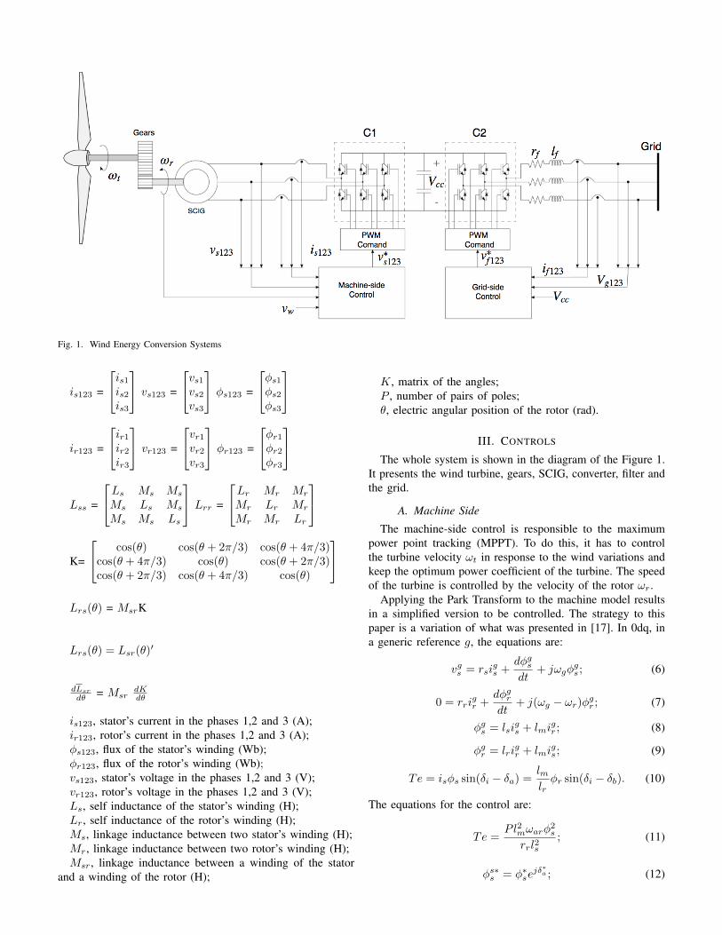
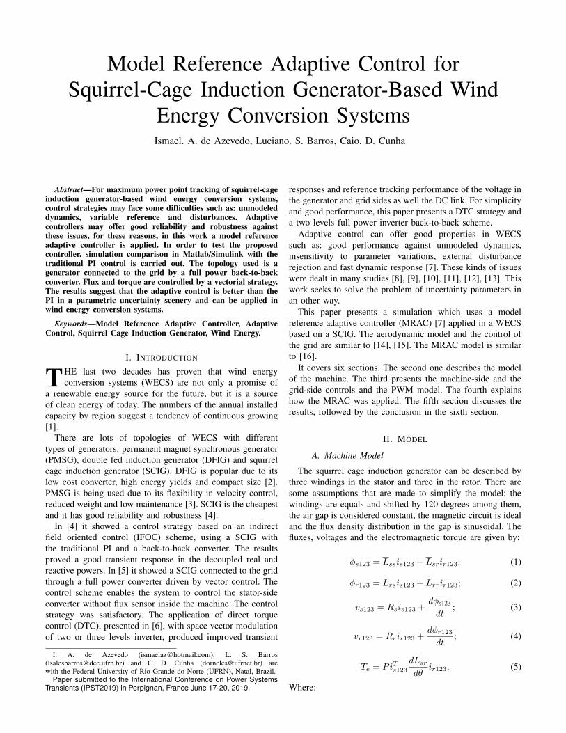
Fig. 1. Wind Energy Conversion Systems
is123 =
is1is2is3
vs123 =
vs1vs2vs3
φs123 =
φs1φs2φs3
ir123 =
ir1ir2ir3
vr123 =
vr1vr2vr3
φr123 =
φr1φr2φr3
Lss =
Ls Ms Ms
Ms Ls Ms
Ms Ms Ls
Lrr =
Lr Mr Mr
Mr Lr Mr
Mr Mr Lr
K=
cos(θ) cos(θ + 2π/3) cos(θ + 4π/3)cos(θ + 4π/3) cos(θ) cos(θ + 2π/3)cos(θ + 2π/3) cos(θ + 4π/3) cos(θ)
Lrs(θ) = MsrK
Lrs(θ) = Lsr(θ)′
dLsr
dθ = MsrdKdθ
is123, stator’s current in the phases 1,2 and 3 (A);ir123, rotor’s current in the phases 1,2 and 3 (A);φs123, flux of the stator’s winding (Wb);φr123, flux of the rotor’s winding (Wb);vs123, stator’s voltage in the phases 1,2 and 3 (V);vr123, rotor’s voltage in the phases 1,2 and 3 (V);Ls, self inductance of the stator’s winding (H);Lr, self inductance of the rotor’s winding (H);Ms, linkage inductance between two stator’s winding (H);Mr, linkage inductance between two rotor’s winding (H);Msr, linkage inductance between a winding of the stator
and a winding of the rotor (H);
K, matrix of the angles;P , number of pairs of poles;θ, electric angular position of the rotor (rad).
III. CONTROLS
The whole system is shown in the diagram of the Figure 1.It presents the wind turbine, gears, SCIG, converter, filter andthe grid.
A. Machine Side
The machine-side control is responsible to the maximumpower point tracking (MPPT). To do this, it has to controlthe turbine velocity ωt in response to the wind variations andkeep the optimum power coefficient of the turbine. The speedof the turbine is controlled by the velocity of the rotor ωr.
Applying the Park Transform to the machine model resultsin a simplified version to be controlled. The strategy to thispaper is a variation of what was presented in [17]. In 0dq, ina generic reference g, the equations are:
vgs = rsigs +
dφgsdt
+ jωgφgs ; (6)
0 = rrigr +
dφgrdt
+ j(ωg − ωr)φgr ; (7)
φgs = lsigs + lmi
gr ; (8)
φgr = lrigr + lmi
gs ; (9)
Te = isφs sin(δi − δa) =lmlrφr sin(δi − δb). (10)
The equations for the control are:
Te =Pl2mωarφ
2s
rrl2s; (11)
φs∗s = φ∗sejδ∗a ; (12)
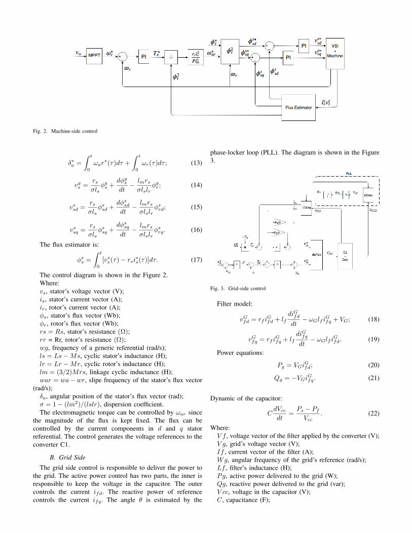
Fig. 2. Machine-side control
δ∗a =
∫ t
0
ωar∗(τ)dτ +
∫ t
0
ωr(τ)dτ ; (13)
vgs =rsσls
φgs +dφgsdt
− lmrsσlslr
φgr ; (14)
vssd =rsσls
φssd +dφssddt
− lmrsσlslr
φsrd; (15)
vssq =rsσls
φssq +dφssqdt
− lmrsσlslr
φsrq. (16)
The flux estimator is:
φss =
∫ t
0
[vss(τ) − rsiss(τ)]dτ. (17)
The control diagram is shown in the Figure 2.Where:vs, stator’s voltage vector (V);is, stator’s current vector (A);ir, rotor’s current vector (A);φs, stator’s flux vector (Wb);φr, rotor’s flux vector (Wb);rs = Rs, stator’s resistance (Ω);rr = Rr, rotor’s resistance (Ω);wg, frequency of a generic referential (rad/s);ls = Ls−Ms, cyclic stator’s inductance (H);lr = Lr −Mr, cyclic rotor’s inductance (H);lm = (3/2)Mrs, linkage cyclic inductance (H);war = wa−wr, slipe frequency of the stator’s flux vector
(rad/s);δa, angular position of the stator’s flux vector (rad);σ = 1 − (lm2)/(lslr), dispersion coefficient.The electromagnetic torque can be controlled by ωar since
the magnitude of the flux is kept fixed. The flux can becontrolled by the current components in d and q statorreferential. The control generates the voltage references to theconverter C1.
B. Grid Side
The grid side control is responsible to deliver the power tothe grid. The active power control has two parts, the inner isresponsible to keep the voltage in the capacitor. The outercontrols the current ifd. The reactive power of referencecontrols the current ifq . The angle θ is estimated by the
phase-locker loop (PLL). The diagram is shown in the Figure3.
Fig. 3. Grid-side control
Filter model:
vGfd = rf iGfd + lf
diGfddt
− ωGlf iGfq + VG; (18)
vGfq = rf iGfq + lf
diGfqdt
− ωGlf iGfd. (19)
Power equations:
Pg = VGiGfd; (20)
Qg = −VGiGfq. (21)
Dynamic of the capacitor:
CdVccdt
=Ps − PfVcc
. (22)
Where:V f , voltage vector of the filter applied by the converter (V);V g, grid’s voltage vector (V);If , current vector of the filter (A);Wg, angular frequency of the grid’s reference (rad/s);Lf , filter’s inductance (H);Pg, active power delivered to the grid (W);Qg, reactive power delivered to the grid (var);V cc, voltage in the capacitor (V);C, capacitance (F);
Pi, power provided by C1 (W);Pf , power provided by C2 (W).
C. PWM Model
The topology of the converters consists of six insulated gatebipolar transistor (IGBTs), two of them for each branch. TheIGBT’s of the same phase cannot conduct at the same time.
The Digital-Scalar Pulse Width Modulation (DS-PWM) isused for the switching control and it was presented in [18]. Itcalculates, for each phase, the interval τ of time that is neededthe switch to conduct.
For each period of PWM the command puts a polevoltage (va0, vb0, vc0) of mean value equals to the sinusoidalreference given by the controller. The pole mean voltage fora phase j is calculated by:
vjo = vref =1
τ[τjVcc2
− (τ − τj)Vcc2
]1
τ(23)
From 23:τj = (
vrefVcc
+1
2)τ (24)
From this equation, it is possible to determine the intervalτ .
IV. MRACA. MRAC description
The project of a controller is made by a transfer functionof a plant. The problem with this kind of approach is thatin some cases there are uncertainties, dynamic changes andunknown parameters. The development of an adaptive controlis a solution for these problems. The idea is to use theinput and the output so that the control can figure out thecharacteristics of the plant and adjust the controller.
There are two kinds of approaches: direct and indirect. Thispaper shows the direct way of adjustment. To achieve it, thereis the MRAC, which uses an ideal plant in comparison with thereal one. The MRAC method control has larger robustness incomparison to fixed parameters controllers. When the outputof the plant is equal to the output of the model reference, itis called matching condition:
limt→∞
e0(t) = 0. (25)
The MRAC strategy requires some assumptions:• The model reference plant must be Strictly Real Positive
(SRP);• The plant must be controllable and observable;• kp and Km must have the same signal.For plants with relative degree larger or equal to 2, in [19]
it showed that it is necessary to introduce an auxiliary signal,so that the augmented error is ruled by a SRP operator. But,for a first order plant model, the control signal u is given by:
u = [θc1θc2]
[yr
]= θTω. (26)
θT is the adaptive array and ω is the regressive array [20].In order to obtain θT , one must integrate the adaptive law, thatis given by:
θ = −γe0ω, γ > 0. (27)
In [21] it was shown that the original MRAC is unstablefor some unmodeled dynamics and external disturbs. In orderto increase robustness in the MRAC, an adaptation law withσ-modification was proposed [22]. It ensured, at least, thelocal stability in presence of unmodeled dynamics and externaldisturbs. Leading to:
θ = −σθ − γe0ω, σ > 0. (28)
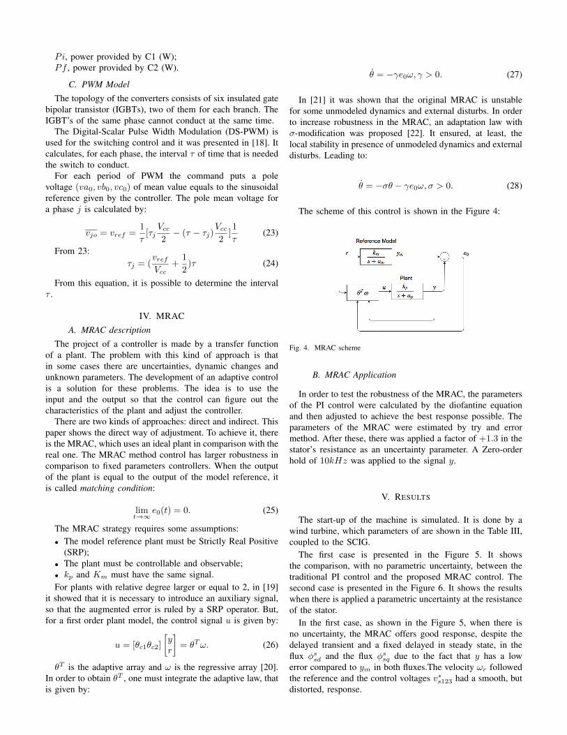
The scheme of this control is shown in the Figure 4:
Fig. 4. MRAC scheme
B. MRAC Application
In order to test the robustness of the MRAC, the parametersof the PI control were calculated by the diofantine equationand then adjusted to achieve the best response possible. Theparameters of the MRAC were estimated by try and errormethod. After these, there was applied a factor of +1.3 in thestator’s resistance as an uncertainty parameter. A Zero-orderhold of 10kHz was applied to the signal y.
V. RESULTS
The start-up of the machine is simulated. It is done by awind turbine, which parameters of are shown in the Table III,coupled to the SCIG.
The first case is presented in the Figure 5. It showsthe comparison, with no parametric uncertainty, between thetraditional PI control and the proposed MRAC control. Thesecond case is presented in the Figure 6. It shows the resultswhen there is applied a parametric uncertainty at the resistanceof the stator.
In the first case, as shown in the Figure 5, when there isno uncertainty, the MRAC offers good response, despite thedelayed transient and a fixed delayed in steady state, in theflux φssd and the flux φssq due to the fact that y has a lowerror compared to ym in both fluxes.The velocity ωr followedthe reference and the control voltages v∗s123 had a smooth, butdistorted, response.

A. Without parametric uncertainty
Fig. 5. PI vs MRAC
MRAC presented a good performance, despite the slowresponse in the transient and the fixed delayed response insteady state. PI presented a good result in the transient and inthe steady state.
B. With parametric uncertainty
In the second case, as shown in the Figure 6, when thereis an uncertainty in the resistance, the MRAC offers thesame quality of response compared to the first case. On theother hand, despite the PI followed the reference initially, iteventually looses the reference. Due to this, the machine does
not accelerate properly and the control voltages v∗s123 increasedbeyond the limit of the converter.
Fig. 6. PI vs MRAC - with uncertainty of 30% in resistance of the stator
VI. CONCLUSION
This paper presented a simulation comparison of PI andMRAC applied to a SCIG with a back-to-back converter basedWECS. As an adaptive controller, MRAC offers reliability androbustness against unmodeled dynamics, variable referenceand disturbances.
The results suggest that, if it is needed to project a controllerfor a plant with uncertainty, the MRAC technique is a goodchoice even though it has a slow response in the transient anda fixed delayed response in steady state. In order to solve these
problems, one may apply a variable state structure [23], butthis should increase complexity and result in high frequencycontrol signals.
Moreover, in this paper it shows that MRAC is robustagainst uncertainty parameters and applicable to wind energyconversion systems, producing good results.
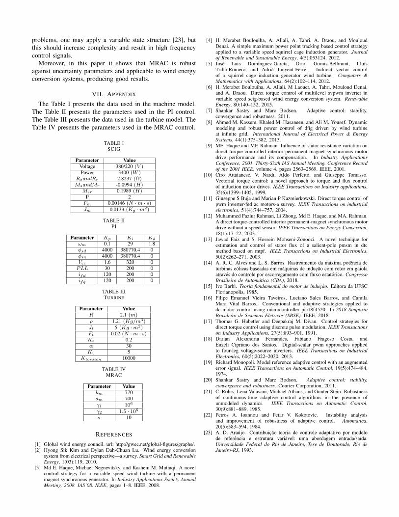
VII. APPENDIX
The Table I presents the data used in the machine model.The Table II presents the parameters used in the PI control.The Table III presents the data used in the turbine model. TheTable IV presents the parameters used in the MRAC control.
TABLE ISCIG
Parameter ValueVoltage 380/220 (V )Power 3400 (W )
RsandRr 2.8237 (Ω)MsandMr -0.0994 (H)
Msr 0.1989 (H)P 2Fm 0.00146 (N ·m · s)Jm 0.0133 (Kg ·m2)
TABLE IIPI
Parameter Kp Ki Kd
ωm 0.1 29 1.8φsd 4000 380770.4 0φsq 4000 380770.4 0Vcc 1.6 320 0PLL 30 200 0ifd 120 200 0ifq 120 200 0
TABLE IIITURBINE
Parameter ValueR 2.1 (m)ρ 1.21 (Kg/m3)Jt 5 (Kg ·m2)Ft 0.02 (N ·m · s)Ks 0.2α 30Kv 5
Ktorsion 10000
TABLE IVMRAC
Parameter Valuekm 770am 700γ1 106
γ2 1.5 · 106
σ 10
REFERENCES
[1] Global wind energy council. url: http://gwec.net/global-figures/graphs/.[2] Hyong Sik Kim and Dylan Dah-Chuan Lu. Wind energy conversion
system from electrical perspective—a survey. Smart Grid and RenewableEnergy, 1(03):119, 2010.
[3] Md E. Haque, Michael Negnevitsky, and Kashem M. Muttaqi. A novelcontrol strategy for a variable speed wind turbine with a permanentmagnet synchronous generator. In Industry Applications Society AnnualMeeting, 2008. IAS’08. IEEE, pages 1–8. IEEE, 2008.
[4] H. Merabet Boulouiha, A. Allali, A. Tahri, A. Draou, and MouloudDenai. A simple maximum power point tracking based control strategyapplied to a variable speed squirrel cage induction generator. Journalof Renewable and Sustainable Energy, 4(5):053124, 2012.
[5] José Luis Domínguez-García, Oriol Gomis-Bellmunt, LluísTrilla-Romero, and Adrià Junyent-Ferré. Indirect vector controlof a squirrel cage induction generator wind turbine. Computers &Mathematics with Applications, 64(2):102–114, 2012.
[6] H. Merabet Boulouiha, A. Allali, M Laouer, A. Tahri, Mouloud Denai,and A. Draou. Direct torque control of multilevel svpwm inverter invariable speed scig-based wind energy conversion system. RenewableEnergy, 80:140–152, 2015.
[7] Shankar Sastry and Marc Bodson. Adaptive control: stability,convergence and robustness. 2011.
[8] Ahmed M. Kassem, Khaled M. Hasaneen, and Ali M. Yousef. Dynamicmodeling and robust power control of dfig driven by wind turbineat infinite grid. International Journal of Electrical Power & EnergySystems, 44(1):375–382, 2013.
[9] ME. Haque and MF. Rahman. Influence of stator resistance variation ondirect torque controlled interior permanent magnet synchronous motordrive performance and its compensation. In Industry ApplicationsConference, 2001. Thirty-Sixth IAS Annual Meeting. Conference Recordof the 2001 IEEE, volume 4, pages 2563–2569. IEEE, 2001.
[10] Ciro Attaianese, V. Nardt, Aldo Perfetto, and Giuseppe Tomasso.Vectorial torque control: a novel approach to torque and flux controlof induction motor drives. IEEE Transactions on Industry applications,35(6):1399–1405, 1999.
[11] Giuseppe S Buja and Marian P Kazmierkowski. Direct torque control ofpwm inverter-fed ac motors-a survey. IEEE Transactions on industrialelectronics, 51(4):744–757, 2004.
[12] Muhammed Fazlur Rahman, Li Zhong, Md E. Haque, and MA. Rahman.A direct torque-controlled interior permanent-magnet synchronous motordrive without a speed sensor. IEEE Transactions on Energy Conversion,18(1):17–22, 2003.
[13] Jawad Faiz and S. Hossein Mohseni-Zonoozi. A novel technique forestimation and control of stator flux of a salient-pole pmsm in dtcmethod based on mtpf. IEEE Transactions on Industrial Electronics,50(2):262–271, 2003.
[14] A. R. C. Alves and L. S. Barros. Rastreamento da máxima potência deturbinas eólicas baseadas em máquinas de indução com rotor em gaiolaatravés do controle por escorregamento com fluxo estatórico. CongressoBrasileiro de Automática (CBA), 2018.
[15] Ivo Barbi. Teoria fundamental do motor de indução. Editora da UFSCFlorianopolis, 1985.
[16] Filipe Emanuel Vieira Taveiros, Luciano Sales Barros, and CamilaMara Vital Barros. Conventional and adaptive strategies applied todc motor control using microcontroller pic18f4520. In 2018 SimposioBrasileiro de Sistemas Eletricos (SBSE). IEEE, 2018.
[17] Thomas G. Habetler and Deepakraj M. Divan. Control strategies fordirect torque control using discrete pulse modulation. IEEE Transactionson Industry Applications, 27(5):893–901, 1991.
[18] Darlan Alexandria Fernandes, Fabiano Fragoso Costa, andEuzeli Cipriano dos Santos. Digital-scalar pwm approaches appliedto four-leg voltage-source inverters. IEEE Transactions on IndustrialElectronics, 60(5):2022–2030, 2013.
[19] Richard Monopoli. Model reference adaptive control with an augmentederror signal. IEEE Transactions on Automatic Control, 19(5):474–484,1974.
[20] Shankar Sastry and Marc Bodson. Adaptive control: stability,convergence and robustness. Courier Corporation, 2011.
[21] C. Rohrs, Lena Valavani, Michael Athans, and Gunter Stein. Robustnessof continuous-time adaptive control algorithms in the presence ofunmodeled dynamics. IEEE Transactions on Automatic Control,30(9):881–889, 1985.
[22] Petros A. Ioannou and Petar V. Kokotovic. Instability analysisand improvement of robustness of adaptive control. Automatica,20(5):583–594, 1984.
[23] A. D. Araújo. Contribuição teoria de controle adaptativo por modelode referência e estrutura variável: uma abordagem entrada/saıda.Universidade Federal do Rio de Janeiro, Tese de Doutorado, Rio deJaneiro-RJ, 1993.