model pro-9776 - voxx electronics · 128-7857 1 of 24 1 select able fea tures the selectable...
TRANSCRIPT

128-78571 of 24
1
SELE
CTAB
LE F
EATU
RES
The
sele
ctab
le fe
atur
es c
an b
e se
t man
ually
as
expl
aine
d be
low,
or w
ith th
e R
F fe
atur
e pr
ogra
mm
er.
To s
et fe
atur
es u
sing
the
RF
prog
ram
mer
, fol
low
the
inst
ruct
ions
pac
kage
d w
ith th
e pr
ogra
mm
er.
Fact
ory
defa
ult s
ettin
gs a
re in
dica
ted
by b
old
text
.N
ote
: The
met
hod
of m
anua
l ove
rride
can
eith
er b
e se
lect
ed to
ope
rate
from
the
vale
t sw
itch
or o
pera
te a
s cu
stom
cod
e.B
e ce
rtain
to p
lace
a c
heck
mar
k in
dica
ting
the
met
hod
used
in th
e bo
x lo
cate
d on
the
last
pag
e of
the
owne
r's m
anua
l.N
OTE
: Key
less
Ent
ry M
odel
s w
ith n
o ho
rn o
utpu
t will
Flas
h th
e P
arki
ng L
ight
s in
stea
d of
chi
rp w
here
chi
rp is
indi
cate
d.A
lso,
No
data
will
be in
dica
ted
if a
feat
ure
is n
ot a
vaila
ble
for a
par
ticul
ar m
odel
. Th
e un
it w
ill en
ter t
he fe
atur
e bu
t no
sele
ctio
n w
ill be
ava
ilabl
e.R
F Pr
ogra
mm
able
Fea
ture
Ban
k 1
Is F
or T
rans
mitt
er P
rogr
amm
ing
See
Tran
smitt
er P
rogr
amm
ing
Gui
de.
RF
Prog
ram
mab
le F
eatu
res
Ban
k 2
Is A
larm
Sel
ecta
ble
Feat
ures
:Fe
atur
e S
elec
tion
1 C
hirp
2 C
hirp
s3
Chi
rps
4 C
hirp
s5
Chi
rps
6 C
hirp
s1s
t Doo
rL/U
L1
Sec.
3.5
Sec
.1
Sec
L, D
bl. U
/LD
bl L
, 1 S
ec U
LD
bl L
, Dbl
UL
1 S
l/35
0mS
ul
2nd
Acc
y Lo
ckA
uto
Lock
On
Aut
o Lo
ck O
ff3r
d A
ccy.
UL
Aut
o U
L D
r.A
uto
UL
All
Aut
o U
L O
ff4t
h H
eadl
ight
sN
ot A
vaila
ble
5th
Pas
sive
Loc
ksP
assi
veA
ctiv
e6t
h P
ass/
Act
Arm
Pas
sive
Arm
Act
ive
Arm
7th
Sire
n/H
orn
Sir
en/H
orn
Sire
n O
nly
Hor
n O
nly
8th
Hor
n C
hirp
10m
S16
mS
30m
S40
mS
50m
S9t
h O
/R M
etho
dC
usto
m C
ode
Vale
t10
th 2
Ste
p U
/LO
nO
ff11
th C
hp D
el T
xO
nO
ff12
th V
olts
/HdW
ireN
ot A
vaila
ble
13th
Trig
ger C
ircui
tsN
ot A
vaila
ble
14th
L/U
L Po
llN
ot A
vaila
ble
15th
Aux
Cha
nnel
5 S
elec
tP
ulse
dP
ush
& H
old
10 S
econ
ds20
Sec
onds
Latc
h O
n/O
ffH
old
3.5
Sec
For
O/P
16th
Aux
Cha
nnel
6 S
elec
tP
ulse
dP
ush
& H
old
10 S
econ
ds20
Sec
onds
Latc
h O
n/O
ffH
old
3.5
Sec
For
O/P
17th
Aux
Cha
nnel
7 S
elec
tP
ulse
dP
ush
& H
old
10 S
econ
ds20
Sec
onds
Latc
h O
n/O
ffH
old
3.5
Sec
For
O/P
18th
Trig
ger D
elay
Not
Ava
ilabl
eW
hen
usin
g th
e R
F pr
ogra
mm
er,
ente
r th
e pr
ogra
m m
ode
as f
ollo
ws:
Turn
the
igni
tion
on.
Pre
ss a
nd r
elea
se v
alet
sw
itch
3 tim
es;
turn
igni
tion
off t
hen
on.
Pre
ss a
nd h
old
vale
t sw
itch
for
5 se
cond
s.S
iren
chirp
s 2
times
indi
catin
g ac
cess
to R
F fe
atur
e pr
ogra
m m
ode.
Mod
el
PRO
-977
6In
stal
latio
n M
anua
l
128-78572 of 24
2
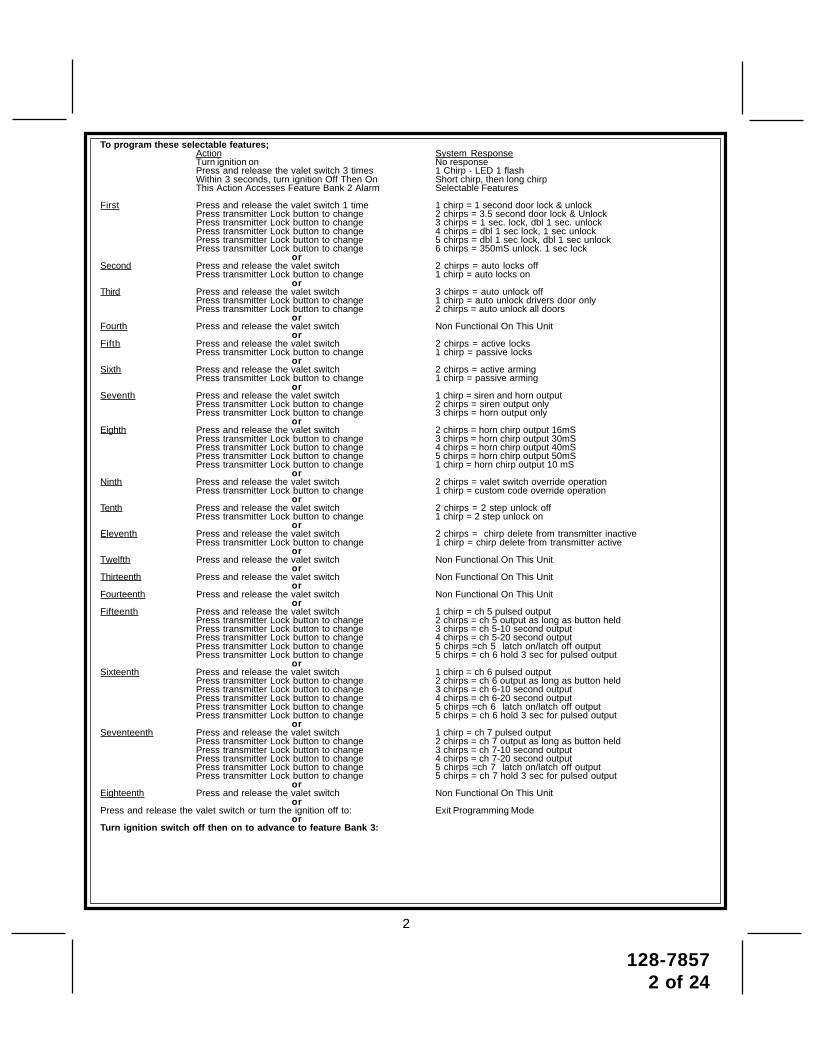
To program these selectable features;Action System ResponseTurn ignition on No responsePress and release the valet switch 3 times 1 Chirp - LED 1 flashWithin 3 seconds, turn ignition Off Then On Short chirp, then long chirpThis Action Accesses Feature Bank 2 Alarm Selectable Features
First Press and release the valet switch 1 time 1 chirp = 1 second door lock & unlockPress transmitter Lock button to change 2 chirps = 3.5 second door lock & UnlockPress transmitter Lock button to change 3 chirps = 1 sec. lock, dbl 1 sec. unlockPress transmitter Lock button to change 4 chirps = dbl 1 sec lock, 1 sec unlockPress transmitter Lock button to change 5 chirps = dbl 1 sec lock, dbl 1 sec unlockPress transmitter Lock button to change 6 chirps = 350mS unlock. 1 sec lock
orSecond Press and release the valet switch 2 chirps = auto locks off
Press transmitter Lock button to change 1 chirp = auto locks onor
Third Press and release the valet switch 3 chirps = auto unlock offPress transmitter Lock button to change 1 chirp = auto unlock drivers door onlyPress transmitter Lock button to change 2 chirps = auto unlock all doors
orFourth Press and release the valet switch Non Functional On This Unit
orFifth Press and release the valet switch 2 chirps = active locks
Press transmitter Lock button to change 1 chirp = passive locksor
Sixth Press and release the valet switch 2 chirps = active armingPress transmitter Lock button to change 1 chirp = passive arming
orSeventh Press and release the valet switch 1 chirp = siren and horn output
Press transmitter Lock button to change 2 chirps = siren output onlyPress transmitter Lock button to change 3 chirps = horn output only
orEighth Press and release the valet switch 2 chirps = horn chirp output 16mS
Press transmitter Lock button to change 3 chirps = horn chirp output 30mSPress transmitter Lock button to change 4 chirps = horn chirp output 40mSPress transmitter Lock button to change 5 chirps = horn chirp output 50mSPress transmitter Lock button to change 1 chirp = horn chirp output 10 mS
orNinth Press and release the valet switch 2 chirps = valet switch override operation
Press transmitter Lock button to change 1 chirp = custom code override operationor
Tenth Press and release the valet switch 2 chirps = 2 step unlock offPress transmitter Lock button to change 1 chirp = 2 step unlock on
orEleventh Press and release the valet switch 2 chirps = chirp delete from transmitter inactive
Press transmitter Lock button to change 1 chirp = chirp delete from transmitter activeor
Twelfth Press and release the valet switch Non Functional On This Unitor
Thirteenth Press and release the valet switch Non Functional On This Unitor
Fourteenth Press and release the valet switch Non Functional On This Unitor
Fifteenth Press and release the valet switch 1 chirp = ch 5 pulsed outputPress transmitter Lock button to change 2 chirps = ch 5 output as long as button heldPress transmitter Lock button to change 3 chirps = ch 5-10 second outputPress transmitter Lock button to change 4 chirps = ch 5-20 second outputPress transmitter Lock button to change 5 chirps =ch 5 latch on/latch off outputPress transmitter Lock button to change 5 chirps = ch 6 hold 3 sec for pulsed output
orSixteenth Press and release the valet switch 1 chirp = ch 6 pulsed output
Press transmitter Lock button to change 2 chirps = ch 6 output as long as button heldPress transmitter Lock button to change 3 chirps = ch 6-10 second outputPress transmitter Lock button to change 4 chirps = ch 6-20 second outputPress transmitter Lock button to change 5 chirps =ch 6 latch on/latch off outputPress transmitter Lock button to change 5 chirps = ch 6 hold 3 sec for pulsed output
orSeventeenth Press and release the valet switch 1 chirp = ch 7 pulsed output
Press transmitter Lock button to change 2 chirps = ch 7 output as long as button heldPress transmitter Lock button to change 3 chirps = ch 7-10 second outputPress transmitter Lock button to change 4 chirps = ch 7-20 second outputPress transmitter Lock button to change 5 chirps =ch 7 latch on/latch off outputPress transmitter Lock button to change 5 chirps = ch 7 hold 3 sec for pulsed output
orEighteenth Press and release the valet switch Non Functional On This Unit
orPress and release the valet switch or turn the ignition off to: Exit Programming Mode
orTurn ignition switch off then on to advance to feature Bank 3:

128-78573 of 24
3
To e
xit p
rogr
am m
ode,
turn
igni
tion
off,
or p
ress
and
rel
ease
val
et s
witc
h.
RF
Prog
ram
mab
le F
eatu
res
Ban
k 3
Is R
emot
e St
art S
elec
tabl
e Fe
atur
es:
Feat
ure
Sel
ectio
n1
Chi
rp2
Chi
rps
3 C
hirp
s4
Chi
rps
5 C
hirp
s6
Chi
rps
1st
Def
rost
Out
put
Pul
sed
10 M
ins
2nd
RF
Star
t Chi
rpO
ffO
nO
n &
Car
finde
r
3rd
Run
Tim
e5
Min
s10
Min
s15
Min
s20
Min
s
4th
Par
king
Lig
hts
On
Stea
dyFl
ashi
ng
5th
Inpu
t Che
ckVo
ltage
Tach
DBI
Tac
h
6th
Volta
ge L
evel
>0.5
V B
4 St
art
< 0.
5V B
4 St
art
7th
Ign.
2 S
elec
tO
ff D
urin
g C
rank
On
Dur
ing
Cra
nkS
ame
As
Acc
y.
8th
Ign.
3 S
elec
tO
ff D
urin
g C
rank
On
Dur
ing
Cra
nkS
ame
As
Acc
yS
Am
e A
s St
arte
r
9th
Dia
gnos
tics
Off
On
10th
Cra
nk T
ime
0.8
Sec
1.0
Sec
1.5
Sec
2.0
Sec
11th
Gas
/Die
sel
Gas
Die
sel 1
0D
iese
l 15
Die
sel 2
0
12th
Tra
nspo
nder
O/P
Whi
le R
/S O
nD
urin
g St
art
Unt
il Ig
n. O
ff
13th
Tem
p St
art
Not
Ava
ilabl
e
14th
Cra
nk A
vera
ging
Ave
ragi
ngPr
eset
Tim
e
Not
e: W
hen
aver
agin
g, th
e en
gine
mus
t be
star
ted
4 tim
es w
ith th
e ke
y to
be
effe
ctiv
e.
15th
R/S
Sho
ckSh
unt
Unt
il C
lear
Shu
nt R
/S C
ycle
Shu
nt F
rom
Tx
16th
Tur
bo S
elec
tO
ff3
Min
s5
Min
s10
Min
s
17th
Bla
ck/B
lue
(Aux
O/P
)S
ingl
e P
ulse
As
Feat
#1
Ban
k 2
Whe
n us
ing
the
RF
prog
ram
mer
, en
ter
the
prog
ram
mod
e as
fol
low
s:
Turn
the
igni
tion
on.
Pre
ss a
nd r
elea
se v
alet
sw
itch
3 tim
es
turn
igni
tion
off t
hen
on;
Pre
ss a
nd h
old
vale
t sw
itch
for
5 se
cond
s.
Sire
n ch
irps
2 tim
es in
dica
ting
acce
ss to
RF
feat
ure
prog
ram
mod
e.
To e
xit p
rogr
am m
ode,
turn
igni
tion
off,
or p
ress
and
rel
ease
val
et s
witc
h.

128-78574 of 24
4
This Remote Start/Alarm System is designed to be used with Automatic Transmission Vehicles Only!The unit provides a selectable ignition control that allows a number of selectable timed outputs for glow plug pre-heat which may be required for certain diesel vehicles, (see selectable feature #9). If the diesel engine has ainstant fire, (no glow plug pre-heat system), feature #9 should remain in the default Gasoline mode setting.For diesel applications, consult your dealer for the type of ignition system used in your particular vehicle.Regardless of the vehicle, Gasoline or Diesel, for every installation, the vehicle MUST HAVE a Tach SignalInput, and an Automatic Transmission.INSTALLATION OF THE MAJOR COMPONENTS:CONTROL MODULE:Select a mounting location inside the passenger compartment (up behind the dashboard). The mountinglocation selected must be within 24" of the ignition switch wiring harness to allow connection of the 6 pin mainwiring harness.Be certain that the chosen location will not interfere with proper operation of the vehicle. Avoid mounting themodule to or routing the wiring around the steering shaft/column, as the module or wiring may wrap around orblock the steering wheel preventing proper control of the vehicle. Secure the module in the chosen locationusing cable ties or screws as necessary.Do Not Mount The Module In The Engine Compartment, as it is not waterproof.SIREN:Select a location in the engine compartment that is not accessible from below the vehicle. The selectedlocation must be clear of hot or moving parts within the engine compartment The siren must be pointeddownward to prevent water retention and the flared end must be pointed away from and out of the enginecompartment for maximum sound distribution. Before securing the siren, check behind your chosen locationto assure that the mounting screws will not penetrate any factory wiring or fluid lines. Secure the sirenmounting bracket using #8 self taping screws or by first using the mounting bracket as a template, scribe ormark the mounting holes. Drill the marked holes using a 1/8" drill bit, then mount the siren using #8 sheetmetal screws.HOOD AND TRUNK PIN SWITCHES:The pin switches included in this package are intended for protecting the hood and trunk areas of the vehicle.In all cases, the switch must be mounted to a grounded metal surface. When the pin switch is activated,(hood/trunk open), it will supply a ground to the input wire activating the alarm. In addition, the hood switchis required for the safety shut down of the remote start unit. If the vehicle is being worked on, this hood switchprevents the remote start activation even if the RF command to start is issued. This switch must be installedin all applications Failure to do so may result in personal injury or property damage. Mount the switches inthe hood and trunk locations away from water drain paths. If necessary, the included brackets may be usedto move the switch away from rain gutters or allow mounting to the firewall behind the hood seal. In bothcases the switch must be set up to allow the hood or trunk door to depress the switch at least 1/4 inch whenthe hood or trunk is closed and fully extended when the hood or trunk is opened. For direct mounting, a 1/4inch hole must be drilled. Carefully check behind the chosen location to insure the drill will not penetrate anyexisting factory wiring or fluid lines. Drill a 1/4" hole in the desired location and thread the pin switch into itusing a 7/16" nut driver or deep well socket. If using the mounting bracket, first secure the bracket to thedesired location and secure the pin switch in the pre-threaded mounting bracket hole.PUSHBUTTON LED SWITCHSelect a mounting location known and accessible to the operator of the vehicle. A dash knockout plug orfront dash panel is desirable as the now Push-Button LED assembly needs the LED to be visible from theoutside of the vehicle and will be used for valet modes, programming features, programming transmitters, andfor overriding the remote start unit when the vehicle is being serviced. Inspect behind the chosen location toinsure that adequate clearance is allowed for the body of the switch, and also that the drill will not penetrateany existing factory wiring or fluid lines. Drill a 5/16" or 8mm hole in the desired location and mount the switchby passing the connectors, one at a time, through the panel from the front side and pressing on the bezel untilthe switch is fully seated.

128-78575 of 24
5
THE RECEIVER/ANTENNA ASSEMBLY:The Superheterodyne Receiver Antenna Assembly provided with this unit allows routing from below the dashboard for maximum operating range. Choose a location above the belt line (dashboard) of the vehicle for bestreception. Special considerations must be made for windshield glass as some newer vehicles utilize ametallic shielded window glass that will inhibit or restrict RF reception. In these vehicles, route the antennatoward a rear window location for best reception. Secure the antenna with double stick tape provided. Aftersecuring the antenna with tape, we advise also securing a section of the antenna cable to a fixed support.This will prevent the antenna from dropping down in case the double stick tape is exposed to extreme heatwhich may loosen it's gummed surface. Route the 3 pin connector toward the control module using cautionnot to pinch the cable as this will cause poor or no RF reception to the control module.SHOCK SENSOR:Select a centrally located, solid mounting surface for the shock sensor that will allow consistent operationfrom all areas of the vehicle. The selected location must be within 18" of the control module to allow routingand connecting of the 4 pin harness. Secure the shock sensor to the chosen location using two #8 self tapingsheet metal screws. The sensor can also be secured to an existing dash brace using cable tie straps.Whichever mounting method is used be sure to allow access to the sensitivity adjustment potentiometer foruse later in the installation.STARTER INHIBIT RELAY:Select a mounting location within 12" of the ignition switch's low current start solenoid wire. Secure the relayto an existing harness in the chosen location using a cable tie around the relay's wiring harness. Caution! Donot wire tie the metal bracket to an existing wiring harness as vibration may cause chaffing and shortingdamaging the factory wiring. If an existing harness is not available then secure the relay's metal mounting tabto an under dash metal brace with a #8 self taping sheet metal screw. Wire the relay as per the diagram foundlater in this manual.This system is to be used in vehicles with AUTOMATIC TRANSMISSIONS only! Although this combinationAlarm/Remote Start unit is a sophisticated system with many advanced features, IT MUST NOT be installedinto a vehicle with a manually operated transmission. Doing so may result in serious personal injury andproperty damage.
I M P O R T A N T !DO NOT PLUG THE SIX PIN MAIN POWER HARNESS OR THE MULTI PIN INPUT / OUTPUT HARNESSINTO THE CONTROL MODULE UNTIL ALL CONNECTIONS TO THE VEHICLE HAVE BEEN MADE. AFTERSELECTING YOUR TARGET WIRES AS DEFINED BELOW, DISCONNECT THE NEGATIVE BATTERY CABLEFROM THE VEHICLE BATTERY PRIOR TO MAKING ANY CONNECTIONS.WIRING THE 6 PIN MAIN POWER HARNESS:Note: Do not remove the fuse holders from this wire harness. Fuses must be used and located asclose as possible to the power source for adequate protection of the vehicle.
Fused RED w/ WHITE TRACE WIRE: + 12 volt Battery 1 SourceLocate the vehicle battery wire(s) at the ignition switch. Verification: These wires will register voltage in allpositions of the ignition switch. Connect the Red w/White wire to the vehicle's battery wire. This wire providespower for the control circuit as well as the ignition 1 and ignition 2 relays.
Fused RED WIRE: + 12 Volt Battery 2 SourceLocate the vehicle battery wire(s) at the ignition switch. Verification: These wires will register voltage in allpositions of the ignition switch. Connect the Red wire to the vehicle's battery wire. This wire provides powerfor the start relay and the accessory relay.
I M P O R T A N T !IT IS THE RESPONSIBILITY OF THE INSTALLING TECHNICIAN TO DETERMINE THE LOAD FACTOR OFTHE VEHICLES ELECTRICAL CIRCUITS WHEN THE VEHICLE IS RUNNING AND TO ADEQUATELY FUSETHE TWO POWER WIRES BASED ON THAT LOAD. IF THE VEHICLE, RUNNING UNDER LOAD WITHTHE AIR CONDITIONER, HEATER BLOWER MOTOR, AND ACCESSORIES EXCEEDS 24 AMPS CON-TINUOUS, WE RECOMMEND THAT TWO FUSES BE USED IN COMBINATION ON EACH POWER WIRE ASSHOWN BELOW. FOR ADDITIONAL INFORMATION SEE TECH UPDATE ISSUED 9/30/96.

128-78576 of 24
6
YELLOW WIRE: Starter OutputCareful consideration for the connection of this wire must be made to prevent the vehicle fromstarting while in gear. Understanding the difference between a mechanical and an electrical Neu-tral Start Switch will allow you to properly identify the circuit and select the correct installationmethod. In addition you will realize why the connection of the safety wire is required for allmechanical switch configurations.Failure to make this connection properly can result in personal injury and property damage. In all installationsit is the responsibility of the installing technician to test the remote start unit and assure that the vehiclecannot start via RF control in any gear selection other than park or neutral.In both mechanical and electrical neutral start switch configurations, the connection of the Yellow wire will bemade to the low current start solenoid wire of the ignition switch harness. This wire will have +12 volts whenthe ignition switch is turned to the start (crank) position only. This wire will have 0 volts in all other ignitionswitch positions.
NOTE: This wire must be connected to the vehicle side of the starter cut relay (when used). For the electricalneutral switch configuration, this connection must be made between the starter inhibit relay, (when used) and
the neutral safety switch as shown in the following diagram.Failure to connect this wire to the ignition switch side of the neutral safety switch can result in personal injuryand property damage.SEE NEUTRAL START SAFETY TEST FOR FURTHER DETAILS.
YELLOW START WIRE DETAIL
BLUE Wire: Ignition 1 OutputConnect this wire to the ignition 1 wire from the ignition switch. This wire will show +12 volts when the ignitionkey is turned to the "ON" or "RUN" and the "START" or CRANK" positions, and will have 0 volts when the keyis turned to the "OFF" and "ACCESSORY" positions.For Diesel Applications, this wire must be connected to the ignition circuit that powers the glow plugs if thevehicle requires glow plug pre-heating. (See selectable feature #9)GREEN Wire: Ignition 2 OutputConnect this wire to the ignition 2 wire from the ignition switch. This wire will show + 12 volts when the ignitionkey is turned to the "ON" or "RUN" position and is some cases the "START" or CRANK" position. This wirewill show 0 volts when the key is turned to the "OFF" and "ACCESSORY" positions.
128-78577 of 24
7
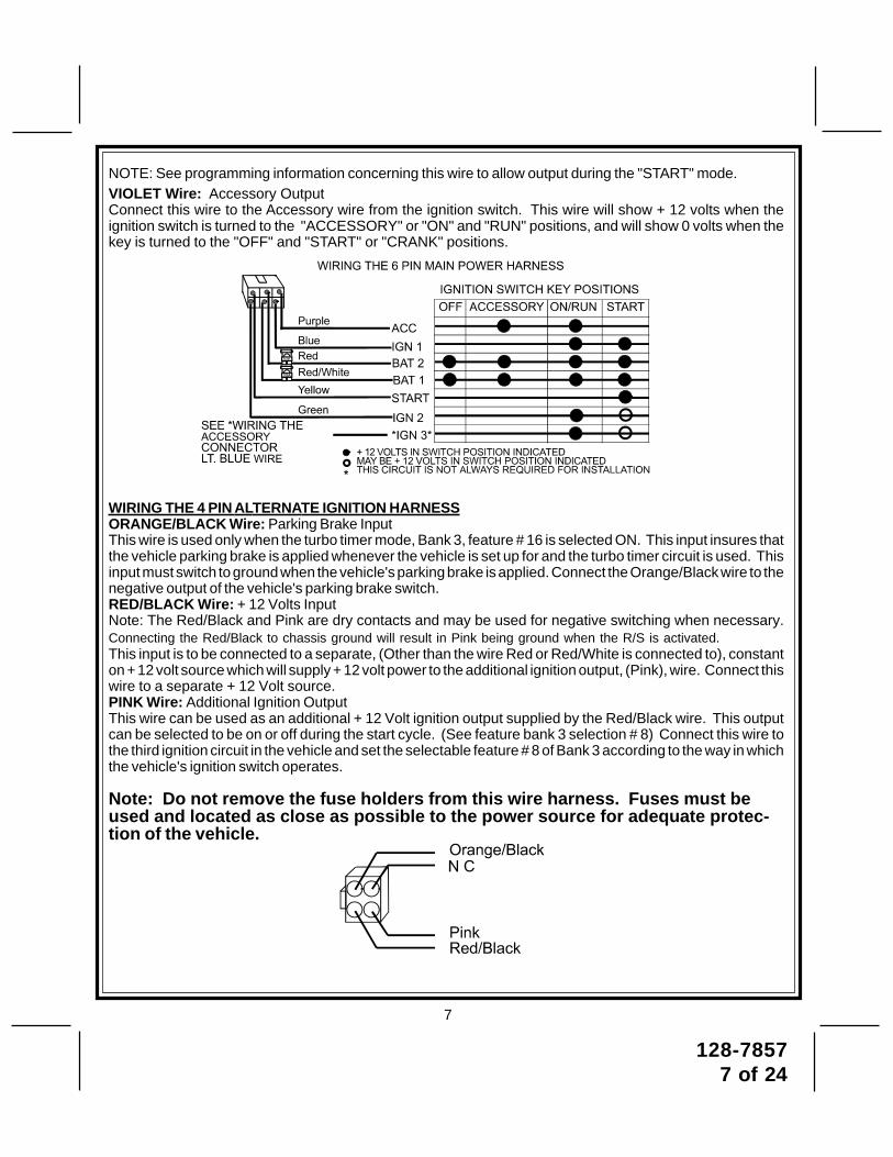
NOTE: See programming information concerning this wire to allow output during the "START" mode.VIOLET Wire: Accessory OutputConnect this wire to the Accessory wire from the ignition switch. This wire will show + 12 volts when theignition switch is turned to the "ACCESSORY" or "ON" and "RUN" positions, and will show 0 volts when thekey is turned to the "OFF" and "START" or "CRANK" positions.
WIRING THE 4 PIN ALTERNATE IGNITION HARNESSORANGE/BLACK Wire: Parking Brake InputThis wire is used only when the turbo timer mode, Bank 3, feature # 16 is selected ON. This input insures thatthe vehicle parking brake is applied whenever the vehicle is set up for and the turbo timer circuit is used. Thisinput must switch to ground when the vehicle's parking brake is applied. Connect the Orange/Black wire to thenegative output of the vehicle's parking brake switch.RED/BLACK Wire: + 12 Volts InputNote: The Red/Black and Pink are dry contacts and may be used for negative switching when necessary.Connecting the Red/Black to chassis ground will result in Pink being ground when the R/S is activated.This input is to be connected to a separate, (Other than the wire Red or Red/White is connected to), constanton + 12 volt source which will supply + 12 volt power to the additional ignition output, (Pink), wire. Connect thiswire to a separate + 12 Volt source.PINK Wire: Additional Ignition OutputThis wire can be used as an additional + 12 Volt ignition output supplied by the Red/Black wire. This outputcan be selected to be on or off during the start cycle. (See feature bank 3 selection # 8) Connect this wire tothe third ignition circuit in the vehicle and set the selectable feature # 8 of Bank 3 according to the way in whichthe vehicle's ignition switch operates.
Note: Do not remove the fuse holders from this wire harness. Fuses must beused and located as close as possible to the power source for adequate protec-tion of the vehicle.

128-78578 of 24
8
WIRING CONNECTIONS: Multi Pin Accessory Input/Output HarnessWhite w/ Red Trace Wire: Parking Light Flasher FeedThis wire is the common contact of the on board parking light flasher relay. If the vehicle you are workingon has +12 volt switched parking lights, connect this wire to a fused + 12 volt source. (Max. 15 Amps)NOTE: If the vehicle's parking lights are ground switched, connect this wire to chassis ground.White Wire: Parking Light Flasher OutputThis wire is the normally open contact of the on board parking light flasher relay. Connect this wire to thevehicle parking light feed wire. See diagram below for details on wiring positive switched parking lightcircuits.
White w/ Black Trace Wire: (+) Siren OutputThis is the positive siren feed wire. Route this wire through a grommet in the firewall to the sirenlocation. Connect the White w/ Black Trace wire to the Red wire of the Siren. Secure the Black wireof the Siren to a known chassis ground or solid clean metal surface.
Parking Light Wiring Detail
Siren Wiring DetailSIREN
BLACK(-) TO VEHICLE'S CHASSIS GROUND
TO WHITE w/BLACK WIRE OF MODULE
RED

128-78579 of 24
9
Purple Wire: (+) Door Trigger InputIf the vehicle's door courtesy light switches + 12 volts when the door is opened, (Some Fords and someImports), you must connect this wire to the positive output from one of the vehicle's door pin switches. Inmost cases, the Purple wire will need to be connected to only one door switch no matter how many doorsthe vehicle has as most door lighting circuits are wired in parallel.Note: For vehicles with interior delay lighting see programming under title "Completing The Installation".
Positive Door Switch Wiring Detail
Hood Pin Switch Detail
Dark Green Wire: (-) Instant Trigger InputThis is the instant on ground trigger input wire. This wire must be connected to the hood and trunk pinswitches previously installed.Note: This wire will be shunted when remote control channel 3 is accessed, (trunk release). This wire willremain shunted all the while there is ground present and for 5 seconds after the ground is removed. Thisallows the operator to open the trunk via the remote transmitter without having to first disarm the alarmsystem. See below for wiring detail.

128-785710 of 24
10
General Motors VATS By-Pass Diagram
Light Blue Wire: Ignition 3 OutputThis wire provides a 300mA ground output that becomes active 3 seconds before the Remote Start Unitinitializes, and remains grounded while running plus an additional 4 seconds after the Remote Start Unitturns off. In all of the applications described below, a relay will be required.The Light Blue wire can be used to accommodate the following situations:A. Shock Sensor By Pass:
If there is a Non Plug in Shock Sensor used with the alarm system and it is not shunted during theRemote Start activation period, then vibration from the running vehicle can cause the alarm to trigger. Inthis case, connect the Light Blue Wire to terminal #86 of a external relay. Connect terminal # 85 of therelay to a fused + 12 volt battery source. Cut the shock sensor trigger wire and connect one end of thecut wire to terminal #30 and the other end of the cut wire to terminal #87a. Just before the Remote Startunit is activated, the relay contacts will open, preventing the shock sensor's operation until the RemoteStart unit shuts off.
B. Ignition 3 Output:Some newer vehicles use a third ignition wire which is required to start and keep the vehicle's enginerunning. If this is the case, connect the Light Blue wire to terminal #86 of an external relay. Connectterminal # 30 & # 85 to a fused + 12 volt battery source rated for a minimum of 25 Amp. Connectterminal # 87 to the third ignition wire in the vehicle.
C. GM VATS Key Override:If the vehicle has the General Motors VATS system installed, you will need to bypass the system whilethe vehicle is operating under the control of the Remote Start Unit. To Do This;1. Measure the resistance of the resistor pellet on the ignition key then select a resistor within 5% of the
key's value from the resistor pack supplied.2. Locate the pair of VATS wires in the vehicle, usually a pair of thin gauge wires running from the
ignition switch to the VATS control module.NOTE: These wires are typically White w/ Black trace and Violet w/ Yellow trace, however in later modelCadillacs, they are run through an orange sleeve, and are either both Black, both Yellow, or both Whitewires. Consult the factory service manual for additional information.
3. Connect the Light Blue Wire from the Remote Start Unit to terminal #86 of an external relay. Connectterminal #85 of the relay to a fused + 12 volt battery source.
4. Cut (#1) wire (as shown), and connect the ignition switch side of the cut wire to terminal #87a of therelay. Connect the other side of the (#1) wire to terminal #30.
5. Connect the previously selected resistor from terminal #87 to the second (#2) wire (as shown).NOTE: The above information and following diagram is for the GM VATS system only. For GM PASSLOCK System you will require the Audiovox AS-PASS II Module.

128-785711 of 24
11
Green w/ White trace Wire: Entry Illumination Ground OutputThis wire provides a 30 second ground output (300 mA Max.) whenever the remote is used to disarm thealarm or to unlock the doors and provides a continuous pulsed output whenever the alarm is triggered. Thiswire should be connected to an external relay, and wired to the vehicles interior entry lighting whenever theoptional Interior Illumination circuit is desired. See below for relay wiring details.
Entry Illumination Detail
Grey w/ Black Trace Wire: Negative Inhibit InputThe Grey w/ Black Trace wire provides an instant shutdown for the Remote Start Control Module wheneverit is grounded. Connect the Grey w/ Black trace wire to the hood pin switch previously installed. This wiremust be routed through a grommet in the firewall and connected to the hood pin switch. If the pin switchis to be used with an alarm system, connect this wire using the diode assembly provided.IMPORTANT! This connection is a safety wire and must be connected as shown and tested as specified.Failure to do so may result in personal injury or property damage. See detail of wiring in the followingdiagram. This wire may also be used if the vehicle brake light circuit switches ground to the brake lights.An isolation diode must be used for ground switched brake light circuits and must be connected to theoutput of the brake switch.
Grey w/ Black Trace Negative Inhibit Safety Shut Down Detail

128-785712 of 24
12
Orange Wire: Ground When Armed OutputThis wire provides a 300 mA ground output when the alarm circuit is armed to control the starter inhibitrelay. Connect the Orange wire to terminal #86 (orange wire) of the relay provided. Connect terminal #85(red wire) of the relay to an ignition wire in the vehicle that is +12 volts when the ignition switch is turned tothe on and start positions and off when the key is off. Locate and cut the low current start solenoid wirefound at the vehicles ignition switch harness. This wire will have + 12 volts when the ignition key is movedto the start (crank) position and will have 0 volts in all other key positions. Connect one side of the cut wireto terminal #87a ( Black wire) of the relay. Connect the other side of the cut wire to terminal #30 (White/Black wire) of the relay. See below for detail of wiring, also see Yellow Start wire detail for connection tovehicle considerations.
Brown w/ Black Trace Wire: Positive Inhibit InputThe Brown w/ Black Trace wire provides an instant shutdown for the Remote Start Control module when-ever it gets + 12 volts. If the Brake lights switch in the vehicle switches + 12 volts to the brake light circuit,connect the Brown w/ Black trace wire to the output side of the brake switch. This will allow the RemoteStart to shut down if an attempt is made to operate the vehicle without the key while running under thecontrol of the Remote Start. In most vehicles, in order to shift into gear, the brake pedal must be de-pressed. The brake input will in turn cause the remote start unit to shut off. See detail in the followingdiagram for wiring the brake light circuit.
Brake Switch Positive Shutdown Detail
Starter Inhibit Wiring Detail
BlackWhite/Black

128-785713 of 24
13
Black Wire: Chassis Ground SourceConnect the Black wire to a known vehicle ground source or to a solid clean metal part of the chassis. Becertain to remove any paint or grease and secure this wire with a self taping screw and ring terminal.
Chassis Ground Connection Detail
Green w/ Orange Trace Wire: Tachometer Input SignalThis wire will continually monitor the engine's tach rate while the unit is under power of the Remote Startmodule. This wire will be routed to the vehicle ECM tach input or through the firewall into the enginecompartment and connect to the negative side of the ignition coil. This Remote Start unit learns the tachrate of the vehicle and in most cases will operate properly from one multi coil pack regardless of the numberof cylinders. If the vehicle has a single coil unit for each cylinder, it may be necessary to connect this wireto more than one cylinder for proper tach reference. See multi coil wiring detail shown later in this manualfor additional information.
Tachometer Input Wiring Detail
Green/Yellow Wire: Diesel Wait To Start InputThe Green/Yellow wire will connect to a diesel vehicles glow plug wire. When the unit receives a start command,this wire must go to + 12 then to ground to allow the crank sequence to begin. When ignition #1 is activated by theremote start unit, the glow plug circuit gets energized, (+ 12 volts), when the glow plug circuit of the vehicle dropsthe + 12 volts, which effectively grounds the wait to start input, then 500mS later the starter will engage. This wirecan also be connected to the Glow Plug Bulb wire in the vehicle if this bulb wire gets + 12 volts when the ignitioncomes on and drops low when the glow plug circuits temperature is reached. Be sure to fuse the wire with a 1 AmpFuse when connecting to a high current circuit such as a factory glow plug wire. The fuse should be installed asclose to the high current wire as possible. If you are installing this unit in a Gasoline vehicle, this wire is not used.NOTE: If the Glow Plug sense wire, Green/Yellow is connected, this wire will have priority over the setting of feature
Bank 3 Feature #11.
Brown Wire: Negative Door TriggerIf the vehicle's door courtesy light switches ground when the door is opened, (Most GMs and Imports), youmust connect this wire to the negative output from one of the vehicle's door pin switches. In most cases theBrown wire will need to be connected to only one door switch no matter how many doors the vehicle has asmost door lighting circuits are wired in parallel.Note: For vehicles with interior delay lighting see programming under title "Completing The Installation".

128-785714 of 24
14
Negative Door Switch Wiring Detail
Dark Blue Wire: Delayed 300mA Pulsed Channel 3 OutputThe Dark Blue wire supplies a 300mA ground pulsed output whenever channel three of the receiver is accessed.Pressing the pre-programmed transmitter button for three seconds will access channel two. This is a lowcurrent output and must be connected to a relay to supply power to the trunk release or the circuit you wishto control. Connect the Dark Blue wire to terminal # 86 of a VF45F11 P&B relay or equivalent. Connectterminal # 85 of the relay to a fused + 12 volt source. Connect the common, normally open, and normallyclosed contacts of the relay to perform the selected function of channel 3. See below for relay wiring detail.Channel 3 Relay Wiring Detail
Green w/ Black Trace Wire: 300mA Latched Channel 4 OutputThe Green w/ Black Trace wire supplies a 300 mA switched output whenever channel four of the receiver isaccessed. Pressing the pre-programmed transmitter button(s) will access channel four and will remainactive, for up to 8 seconds, as long as the transmitter button(s) is held. This is a low current output and mustbe connected to a relay to supply power to the device you intend to control. Connect Green w/ Black Tracewire to terminal #86 of a VF45F11 P&B relay or equivalent. Connect terminal #85 of the relay to a fused + 12volt source. Connect the common, normally open, and normally closed contacts of the relay to perform theselected function of the channel 4 output.Dark Blue/Black Trace Wire: External Trigger InputThe Dark Blue/Black trace wire allows the remote start unit to be activated from an external source. Theintent of this wire is to allow the unit to be controlled from a "POSSE/CAR-LINK" paging system or similardevice. When this wire receives a ground pulse, the unit will start the vehicle. Connect this wire to a groundpulsed output from the controlling circuit.Black w/ White Trace Wire : 300 mA Horn OutputThe black w/ white trace wire is provided to beep the vehicle’s horn. This is a transistorized low current output,and should only be connected to the low current ground output from the vehicle’s horn switch.If the vehicle uses a + 12 VDC horn switch, then connect the black w/ white trace wire to terminal 86 of the AS9256 relay ( or an equivalent 30 Amp automotive relay ), and connect relay terminal 85 to a fused + 12 VDCbattery source. Connect relay terminal 87 to the vehicle’s horn switch output, and connect relay terminal 30to a fused + 12 VDC battery source.

128-785715 of 24
15
WIRING THE 4 PIN AUXILIARY OUTPUT HARNESSThe auxiliary 4 pin connector provides low current outputs to control various functions in the vehicle duringdifferent stages of the Remote Start unit's operation. Understanding these outputs and the time in which theyoccur will allow you to determine if they are needed for the particular vehicle you are working on as well as howto use them.Black w Blue Trace Wire: Pulsed Ground Output Before StartThe Black w/ Blue Trace wire will provide a 1 second 300 mA pulsed ground output 1.5 second before theremote start unit activates as well as when the transmitter is used to disarm the system. Typical use for thisoutput would be to disarm a factory theft deterrent system to prevent false triggering of the factory alarm whenthe remote start unit engages or when the 785 is used to unlock the doors.Black w/ Light Green Trace Wire: Pulsed Ground Output After StartThe Black w/ Light Green Trace wire will provide a 1 second mA pulsed ground output after the vehicle isstarted under control of the remote start unit. Typically this wire will be used to re-lock the vehicle doors if thedoors unlock automatically when the factory anti-theft system is disarmed.Black w/ Red Trace Wire: Pulsed Ground Output After ShutdownThe Black w/ Red Trace wire will provide a 1 second 300 mA pulsed ground output after the remote start unitshuts down. This output will occur regardless of whether the circuit times out or is manually terminated.Typically this output will be used to re-lock the vehicle doors if the doors unlock automatically when theignition circuit transitions to off.Black w/ Yellow Trace Wire: Ground Output During Start (Crank)The Black w/ Yellow Trace wire will provide a 300 mA ground output while the starter output of the remote startunit is active. This output can be used to activate the Crank Low/Bulb Test wire found in some GM vehicles.This wire is also referred to as the ECM wake up wire in some vehicles.NOTE: The outputs above are low current outputs and must be used with a relay if the circuit's requirement
is more than 300mA.3 Pin Auxiliary Outputs 5, 6, & 7Lt Blue/Green Wire : DELAYED 300 mA PULSED OUTPUT / CHANNEL 5The light blue/green wire pulses to ground via an independent RF channel from the keychain transmitter. Thisis a transistorized, low current output, and should only be used to drive an external relay coil.WARNING: Connecting the light blue/green to the high current switched output of trunk release circuits, some
remote start trigger inputs, will damage the control module.Connect the light blue/green to terminal 86 of the AS - 9256 relay (or equivalent 30 A automotive relay) and wirethe remaining relay contacts to perform the selected function of channel 5.Lt Blue/Black Wire : DELAYED 300 mA PULSED OUTPUT / CHANNEL 6The light blue/green wire pulses to ground via an independent RF channel from the keychain transmitter. Thisis a transistorized, low current output, and should only be used to drive an external relay coil.WARNING: Connecting the light blue/black to the high current circuits, will damage the control module.Connect the light blue/black to terminal 86 of the AS - 9256 relay (or equivalent 30 A automotive relay) and wirethe remaining relay contacts to perform the selected function of channel 6.Blue/Red Wire : DELAYED 300 mA PULSED OUTPUT / CHANNEL 7The light blue/red wire pulses to ground via an independent RF channel from the keychain transmitter. This isa transistorized, low current output, and should only be used to drive an external relay coil.WARNING: Connecting the light blue/red to the high current circuits, will damage the control module.Connect the light blue/red to terminal 86 of the AS - 9256 relay (or equivalent 30 A automotive relay) and wirethe remaining relay contacts to perform the selected function of channel 7.4 Pin Shock Sensor: (White Connector)The Red (+12 volt), Black (ground), Blue (pre-detect) and Green (full trigger when armed) wires loaded into thewhite connector shell are the inputs/outputs of the shock sensor. Route the 4 wire harness from the shocksensor to the remote start control unit and plug the 4 pin white connector into the mating 4 pin connector shellof the control module.Note: While operating under the control of the remote start unit the shock sensor will be shunted (bypassed).
Once the remote start shuts down, the shock sensor will be re-enabled.

128-785716 of 24
16
2 Pin Transponder Control Output: (Yellow Connector)This output is intended to allow the control of a transponder bypass interface module or transponderbypass relay. The system also allows software selections to control the way in which this output oper-ates, see remote start feature # 10 for setting this output.When the unit is selected for output during the start sequence, this output will be active at the same timeIgn. 3 becomes active, and will remain active until the vehicle has started. This will be used for one timeread transponder circuits.When the unit is selected for transponder on, this output will become active at the same time ign. 3becomes active, and will remain active all the time the unit is operational under the control of the remotestart. When the unit is selected for continuous and the vehicle is started via the Remote Start, this outputwill become active at the same time ign. 3 becomes active and will remain active until the ignition in thevehicle goes low. This will allow the unit to be used for continuous read transponders circuits.Push Button LED/Valet/Program/Override Switch: (Blue & White Connectors)The Black & Grey and the Red Blue twin lead wires loaded in the 2 two connector are the ground supply andprogram/valet/override input as well as anode & cathode of the PBLED switch for the remote start unit. Whenthe Grey wire is grounded, under certain conditions, the unit will enter the valet mode. When the Grey wire issequentially grounded under other conditions, the unit will enter the various program modes indicated on theintegral LED built into the switch. Route the twin lead Black and Grey and Red Blue wires from the PBLEDswitch to the remote start unit and plug both two pin connector into the mating blue and white connector shellof the control module. For valet, remote start override, and alarm override information, refer to the ownersmanual.3 Pin Antenna/Receiver Connector:Plug the previously routed three pin connector from the antenna receiver assemble into the mating connectorof the control module. This connector supplies 12 volts, ground and RF data from the antenna receiver to theremote start module. Be certain this connector is firmly seated making good contact to the control unit.3 Pin Door Lock/Unlock Harness: (White Connector)The Red and Green wires will provide either a pulsed ground output to the factory door lock control relay, or apulsed + 12 volt output to the factory door lock control relay. In either case, the maximum current drawthrough these outputs must not exceed 300mA. The Red w/Black trace wire will provide a pulsed groundonly, and will only provide an output when the unlock button of the transmitter is pressed a second time aftera first unlock command was issued. This is used for second step unlock or all doors unlock in a two stepcircuit. In this arrangement, Red is used to control the drivers door unlock relay, and the Red/Black will beused to control unlock of all other doors.3 Wire Ground Switched Door Lock Circuits:In this application, the Red wire of the door lock harness provides a ground pulse during the arming sequence,or pulsed ground lock output. Connect the Red wire to the low current ground signal wire from the factory doorlock switch to the factory door lock relay.The Green wire of the door lock harness provides a ground pulse during the disarming sequence, or pulsedground unlock output. Connect the Green wire to the low current ground signal wire from the factory doorunlock switch to the factory door unlock relay. See Below For Wiring Detail.
3 Wire Ground Switched Door Lock/Unlock Wiring Detail
128-785717 of 24
17
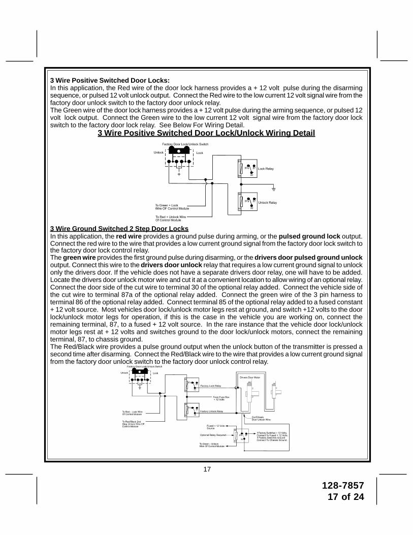
3 Wire Positive Switched Door Locks:In this application, the Red wire of the door lock harness provides a + 12 volt pulse during the disarmingsequence, or pulsed 12 volt unlock output. Connect the Red wire to the low current 12 volt signal wire from thefactory door unlock switch to the factory door unlock relay.The Green wire of the door lock harness provides a + 12 volt pulse during the arming sequence, or pulsed 12volt lock output. Connect the Green wire to the low current 12 volt signal wire from the factory door lockswitch to the factory door lock relay. See Below For Wiring Detail.
3 Wire Positive Switched Door Lock/Unlock Wiring Detail
3 Wire Ground Switched 2 Step Door LocksIn this application, the red wire provides a ground pulse during arming, or the pulsed ground lock output.Connect the red wire to the wire that provides a low current ground signal from the factory door lock switch tothe factory door lock control relay.The green wire provides the first ground pulse during disarming, or the drivers door pulsed ground unlockoutput. Connect this wire to the drivers door unlock relay that requires a low current ground signal to unlockonly the drivers door. If the vehicle does not have a separate drivers door relay, one will have to be added.Locate the drivers door unlock motor wire and cut it at a convenient location to allow wiring of an optional relay.Connect the door side of the cut wire to terminal 30 of the optional relay added. Connect the vehicle side ofthe cut wire to terminal 87a of the optional relay added. Connect the green wire of the 3 pin harness toterminal 86 of the optional relay added. Connect terminal 85 of the optional relay added to a fused constant+ 12 volt source. Most vehicles door lock/unlock motor legs rest at ground, and switch +12 volts to the doorlock/unlock motor legs for operation, if this is the case in the vehicle you are working on, connect theremaining terminal, 87, to a fused + 12 volt source. In the rare instance that the vehicle door lock/unlockmotor legs rest at + 12 volts and switches ground to the door lock/unlock motors, connect the remainingterminal, 87, to chassis ground.The Red/Black wire provides a pulse ground output when the unlock button of the transmitter is pressed asecond time after disarming. Connect the Red/Black wire to the wire that provides a low current ground signalfrom the factory door unlock switch to the factory door unlock control relay.

128-785718 of 24
18
3 Wire Positive Switched 2 Step Door LocksThe green wire provides a positive pulse during arming, or the pulsed + 12 volt lock output. Connect thegreen wire to the wire that provides a low current positive signal from the factory door lock switch to thefactory door lock control relay.The red wire provides a positive pulse during disarming, or the drivers door pulsed positive unlockoutput. Connect this wire to the drivers door unlock relay that requires a low current positive signal tounlock only the drivers door. If the vehicle does not have a separate drivers door relay, one will have to beadded. Locate the drivers door unlock motor wire and cut it at a convenient location to allow wiring of anoptional relay. Connect the door side of the cut wire to terminal 30 of the optional relay added. Connect thevehicle side of the cut wire to terminal 87a of the optional relay added. Connect the red wire of the 3 pinharness to terminal 86 of the optional relay added. Connect terminal 85 of the optional relay added tochassis ground. Most vehicles door lock/unlock motor legs rest at ground, and switch +12 volts to the doorlock/unlock motor legs for operation, if this is the case in the vehicle you are working on, connect theremaining terminal, 87, to a fused + 12 volt source. In the rare instance that the vehicle door lock/unlockmotor legs rest at + 12 volts and switches ground to the door lock/unlock motors, connect he remainingterminal, 87, to chassis ground.The Red/Black wire provides a pulse ground output when the unlock button of the transmitter is pressed asecond time after disarming. Because the vehicle you are working on requires a positive pulse from thefactory door lock switch to the factory door lock control relay, you will have to add a relay to invert the outputpolarity of this wire. Connect the Red/Black wire to terminal 86 of the optional added relay. Connectterminal 85 & 87 to a fuse + 12 volt source. Connect terminal 30 to the low current door unlock wire from thefactory door switch to the door unlock control relay.
Note: Resistive Circuits, As Well As 4 Wire Polarity Reversal and 5 Wire Alternating 12 VoltDoor Lock Control CircuitsThese applications require the use of additional components which may include relays, fixed resistors, orfor convenience, the AS 9159 Door Lock Interface. Refer to the AUDIOVOX Door Lock Wiring Supplementand or the Audiovox fax back service for information on your particular vehicle for properly connecting tothese types of circuits.

128-785719 of 24
19
TIMED START PROGRAM:The Remote Start unit has the ability to start the vehicle automatically at timed intervals. This feature isuseful in extremely cold climates where starting the engine is the only means to keep the battery chargedand fluids warm. The operator has the option to have the unit start every 2 or 4 hours for a maximum of 48hours. Factory preset is to start at 4 hour intervals. To select 2 or 4 hour automatic start timer:1. Start By Holding the Push Button Switch On.2. While Holding the Push Button Switch Turn The Ignition Switch On Then Off3a) Within 10 seconds of turning the ignition switch off, Release and then Push On and release thePush Button Switch 2 times holding it on the second time until the siren and or lights flash and chirp 2times indicating that the 2 Hour Start Interval has successfully been set. or3b) Within 10 seconds of turning the ignition switch off, (Step 2) Releaseand then Push On and release the Push Button Switch 4 times holding it on the fourth time until thesiren and or lights flash and chirp 4 times indicating that the 4 Hour Start Interval has successfully beenset.NOTE: Once selected, 2 or 4, this timer interval will remain in memory until it is manually changed. Tochange, the above sequence will have to be followed.TIMED START OPERATION:To begin the start timer, within 10 seconds of turning off the ignition switch, activate the RF command tostart 2 times. (Press the trunk/key button four times). The lights will flash and the siren will chirp 4 times.Indicating timed interval mode has been initiated. The vehicle will automatically start every 2 or 4 hours asprogrammed. To cancel the timed start mode start the vehicle either by RF or by the ignition key.Programming Tach Rate:NOTE: All applications require that tach be programmed.The unit will not operate unless tach is programmed. If an attempt is made to start the vehicle via the remotestart without first programming tach, the unit will flash the parking lights 7 times indicating tach has not beenlearned and stored. If the tach rate is not properly programmed to the specific vehicle, the unit may not realizethat the vehicle is running in certain instances reengage the starter motor.The Remote Start Unit will learn the tach rate of most vehicle's single coil, multiple coil packs, or singleinjector. To learn tach.1. Turn the ignition key to the On position.2. Press and release the valet/program push button switch 3 times.3. Immediately turn the ignition key Off.4. Press and hold the valet/program push button switch, then start the vehicle using the key.5. When the unit senses the tach signal, the parking lights will begin to flash.6. Release the valet/program pushbutton switch. The parking lights will turn on for three seconds toindicate that the learned tach signal is stored and the unit is out of the tach learn mode.NOTE: If the unit fails to learn tach rate due to an improper tachometer connection or a poor tach source,theparking lights will not flash.To correct this situation, locate and connect the Green/Orange wire to the proper tach signal, and thenrepeat the tach learn routine.Diagnostics:Enter selectable feature #7 and turn on as described above.NOTE: Diagnostic mode is a temporary mode. Once you have accessed the diagnostic mode, the unit will
pause for two seconds then begin to flash the last stored shut down code. This code will bedisplayed two times in succession, then the unit will automatically exit the diagnostic on mode.
The parking lights will flash a number of times indicating the reason for the last remote start shutdown. Thelight flash indications are as follows:
1 Flash 5, 10, 15, or 20, minute run timer expired.2 Flashes Low or No tach signal received.3 Flashes Positive input shut down.4 Flashes Control switch was moved to "Off" position.5 Flashes RF Shutdown command received.6 Flashes High RPM signal over speed shut down.7 Flashes Tach has NOT learned.8 Flashes Negative input shutdown 4 Flashes Control switch moved to the off position
Multi Coil Pack Adaptor: (Optional)The multi coil pack adaptor is designed for use with vehicles having multiple ignition coils where a singlepoint tach signal is unavailable, or non responsive. P/N 136B1400
128-785720 of 24
20
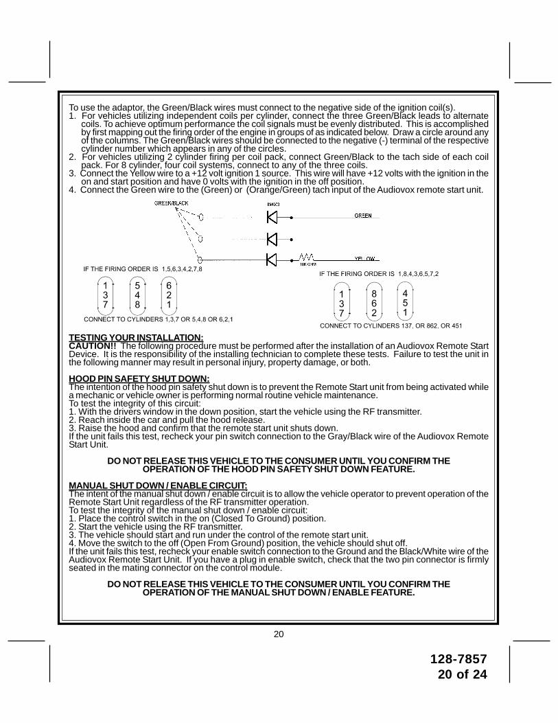
To use the adaptor, the Green/Black wires must connect to the negative side of the ignition coil(s).1. For vehicles utilizing independent coils per cylinder, connect the three Green/Black leads to alternate
coils. To achieve optimum performance the coil signals must be evenly distributed. This is accomplishedby first mapping out the firing order of the engine in groups of as indicated below. Draw a circle around anyof the columns. The Green/Black wires should be connected to the negative (-) terminal of the respectivecylinder number which appears in any of the circles.
2. For vehicles utilizing 2 cylinder firing per coil pack, connect Green/Black to the tach side of each coilpack. For 8 cylinder, four coil systems, connect to any of the three coils.
3. Connect the Yellow wire to a +12 volt ignition 1 source. This wire will have +12 volts with the ignition in theon and start position and have 0 volts with the ignition in the off position.
4. Connect the Green wire to the (Green) or (Orange/Green) tach input of the Audiovox remote start unit.
TESTING YOUR INSTALLATION:CAUTION!! The following procedure must be performed after the installation of an Audiovox Remote StartDevice. It is the responsibility of the installing technician to complete these tests. Failure to test the unit inthe following manner may result in personal injury, property damage, or both.
HOOD PIN SAFETY SHUT DOWN:The intention of the hood pin safety shut down is to prevent the Remote Start unit from being activated whilea mechanic or vehicle owner is performing normal routine vehicle maintenance.To test the integrity of this circuit:1. With the drivers window in the down position, start the vehicle using the RF transmitter.2. Reach inside the car and pull the hood release.3. Raise the hood and confirm that the remote start unit shuts down.If the unit fails this test, recheck your pin switch connection to the Gray/Black wire of the Audiovox RemoteStart Unit.
DO NOT RELEASE THIS VEHICLE TO THE CONSUMER UNTIL YOU CONFIRM THEOPERATION OF THE HOOD PIN SAFETY SHUT DOWN FEATURE.
MANUAL SHUT DOWN / ENABLE CIRCUIT:The intent of the manual shut down / enable circuit is to allow the vehicle operator to prevent operation of theRemote Start Unit regardless of the RF transmitter operation.To test the integrity of the manual shut down / enable circuit:1. Place the control switch in the on (Closed To Ground) position.2. Start the vehicle using the RF transmitter.3. The vehicle should start and run under the control of the remote start unit.4. Move the switch to the off (Open From Ground) position, the vehicle should shut off.If the unit fails this test, recheck your enable switch connection to the Ground and the Black/White wire of theAudiovox Remote Start Unit. If you have a plug in enable switch, check that the two pin connector is firmlyseated in the mating connector on the control module.
DO NOT RELEASE THIS VEHICLE TO THE CONSUMER UNTIL YOU CONFIRM THEOPERATION OF THE MANUAL SHUT DOWN / ENABLE FEATURE.

128-785721 of 24
21
NEUTRAL START SAFETY TEST:The intent of the neutral start switch is to prevent the vehicle from starting while the gear selector is in anyposition other than Park, or Neutral. When installing a Remote Start Device, it is imperative that the YellowStarter wire be connected to the ignition switch side of the Neutral Start Switch. Consideration for the place-ment of a starter inhibit relay is important as well, and should be connected to the ignition switch side of theYellow Start Wire.To test the integrity of the Neutral Start Safety Circuit:1. Set the vehicle parking brake.2. Block the drive wheels to prevent vehicle movement.3. Temporarily disconnect the Brown/Black positive shut down wire from the vehicle's brake switch.4. Sitting in the vehicle, start the engine using the vehicle's ignition key.5. Step on the brake pedal and shift the gear selector into reverse.6. Allow the transmission to shift. When you feel the engine pull, do not move the gear selector just turn the
ignition switch off. DO NOT attempt to remove the key.7. Keeping the brake pedal depressed, activate the RF transmitter in an attempt to start the vehicle. The
car should not start.8. Repeat the above test this time move the gear selector to the drive position. If the unit attempts to start,
failing this test, recheck your Yellow Wire's connection. This wire must be connected to the ignition switchside of the Neutral Start Switch. If the vehicle you are working on does not have an Electrical Neutral SafetySwitch, it will be necessary to reconfigure the Remote Starts Wiring to accommodate this vehicle. Theinformation concerning the Mechanical Neutral Safety Switch provided below will help you to determine ifthe vehicle you are working on has this type of safety switch and will provide alternate wiring methods toaccommodate this situation.
MECHANICAL NEUTRAL SAFETY SWITCH CONSIDERATIONS:Mechanical neutral safety switch configurations differ slightly in that they do not offer the same level of safetywhen installing a remote start device. Often when the ignition switch is turned off while the gear selector is inany position other than park or neutral, the mechanical function will not allow the key to be turned to the startposition or be removed from the ignition cylinder. This configuration prevents mechanical operation while thevehicle is in gear but offers no consideration for electrical operation. Because of this potential problem, thisinstallation requires the additional connection of a safety wire from the remote start device to the vehicle Park/Neutral ECM Input or the vehicle key in sensor. This connection will prevent remote start operation if the keyis left in the ignition switch regardless of the gear selectors position.
PARK / NEUTRAL ECM INPUT:The Park/Neutral ECM input is the preferred method of installation. This not only maintains the integrity of thefactory circuit, it is also the easiest to install, providing the vehicle you are working on has this ECM input.The installation required for this application (shown below), indicates the slight reconfiguration of the controlswitch wiring and the addition of a 4000 series diode. Shown is a typical GM Park/Neutral ECM input circuit.To connect the Audiovox remote start unit to the GM Park / Neutral ECM input:1. Locate the Orange / Black reference wire in the "C2" connector found at the ECM in GM B Body vehicles
or, locate the equivalent reference wire in the vehicle you are installing the Audiovox Remote Start Unit in.2. Connect the Cathode, (Striped) end, of a 4000 series diode to this reference wire.3. Connect the Anode, (Non Striped) end, of the diode to one side of the Remote Start j enable switch.4. Connect the other side of the enable switch to the Black/White enable input wire of the Remote Start unit.The reference diagram below shows a typical GM B Body ECM reference wire and how it is to be connectedto the Remote Start Unit.
128-785722 of 24
22
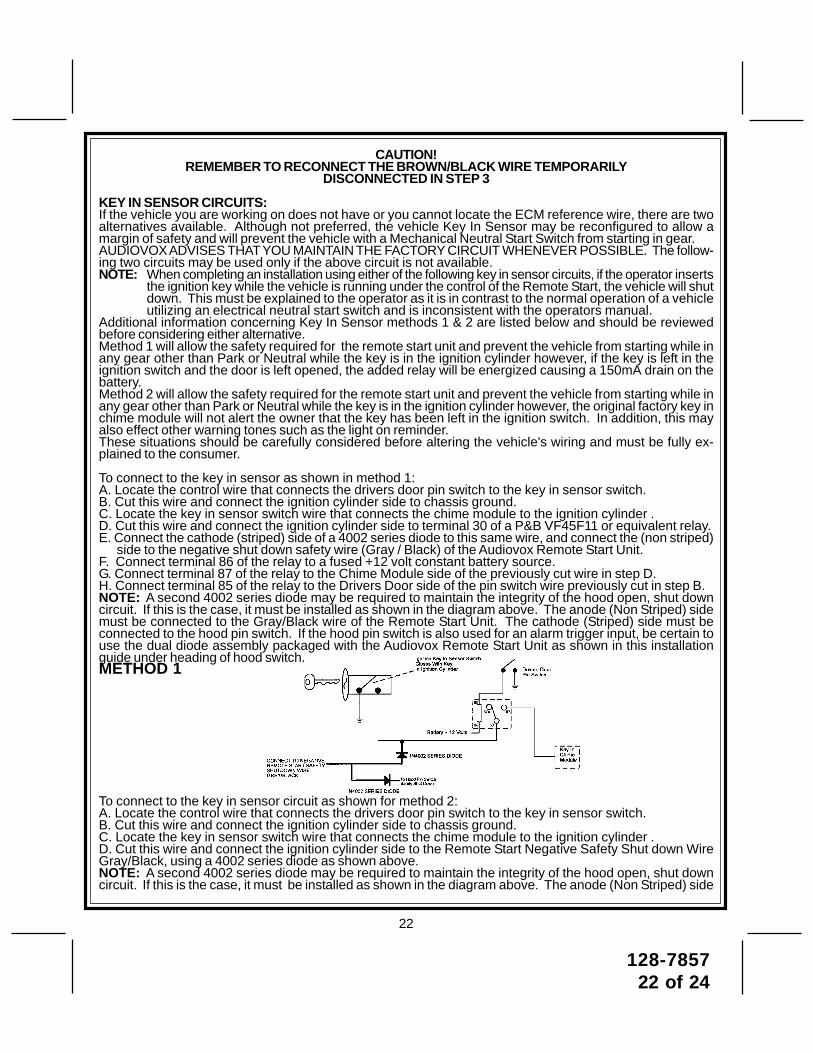
CAUTION!REMEMBER TO RECONNECT THE BROWN/BLACK WIRE TEMPORARILY
DISCONNECTED IN STEP 3
KEY IN SENSOR CIRCUITS:If the vehicle you are working on does not have or you cannot locate the ECM reference wire, there are twoalternatives available. Although not preferred, the vehicle Key In Sensor may be reconfigured to allow amargin of safety and will prevent the vehicle with a Mechanical Neutral Start Switch from starting in gear.AUDIOVOX ADVISES THAT YOU MAINTAIN THE FACTORY CIRCUIT WHENEVER POSSIBLE. The follow-ing two circuits may be used only if the above circuit is not available.NOTE: When completing an installation using either of the following key in sensor circuits, if the operator inserts
the ignition key while the vehicle is running under the control of the Remote Start, the vehicle will shutdown. This must be explained to the operator as it is in contrast to the normal operation of a vehicleutilizing an electrical neutral start switch and is inconsistent with the operators manual.
Additional information concerning Key In Sensor methods 1 & 2 are listed below and should be reviewedbefore considering either alternative.Method 1 will allow the safety required for the remote start unit and prevent the vehicle from starting while inany gear other than Park or Neutral while the key is in the ignition cylinder however, if the key is left in theignition switch and the door is left opened, the added relay will be energized causing a 150mA drain on thebattery.Method 2 will allow the safety required for the remote start unit and prevent the vehicle from starting while inany gear other than Park or Neutral while the key is in the ignition cylinder however, the original factory key inchime module will not alert the owner that the key has been left in the ignition switch. In addition, this mayalso effect other warning tones such as the light on reminder.These situations should be carefully considered before altering the vehicle's wiring and must be fully ex-plained to the consumer.
To connect to the key in sensor as shown in method 1:A. Locate the control wire that connects the drivers door pin switch to the key in sensor switch.B. Cut this wire and connect the ignition cylinder side to chassis ground.C. Locate the key in sensor switch wire that connects the chime module to the ignition cylinder .D. Cut this wire and connect the ignition cylinder side to terminal 30 of a P&B VF45F11 or equivalent relay.E. Connect the cathode (striped) side of a 4002 series diode to this same wire, and connect the (non striped)
side to the negative shut down safety wire (Gray / Black) of the Audiovox Remote Start Unit.F. Connect terminal 86 of the relay to a fused +12 volt constant battery source.G. Connect terminal 87 of the relay to the Chime Module side of the previously cut wire in step D.H. Connect terminal 85 of the relay to the Drivers Door side of the pin switch wire previously cut in step B.NOTE: A second 4002 series diode may be required to maintain the integrity of the hood open, shut downcircuit. If this is the case, it must be installed as shown in the diagram above. The anode (Non Striped) sidemust be connected to the Gray/Black wire of the Remote Start Unit. The cathode (Striped) side must beconnected to the hood pin switch. If the hood pin switch is also used for an alarm trigger input, be certain touse the dual diode assembly packaged with the Audiovox Remote Start Unit as shown in this installationguide under heading of hood switch.METHOD 1
To connect to the key in sensor circuit as shown for method 2:A. Locate the control wire that connects the drivers door pin switch to the key in sensor switch.B. Cut this wire and connect the ignition cylinder side to chassis ground.C. Locate the key in sensor switch wire that connects the chime module to the ignition cylinder .D. Cut this wire and connect the ignition cylinder side to the Remote Start Negative Safety Shut down WireGray/Black, using a 4002 series diode as shown above.NOTE: A second 4002 series diode may be required to maintain the integrity of the hood open, shut downcircuit. If this is the case, it must be installed as shown in the diagram above. The anode (Non Striped) side

128-785723 of 24
23
must be connected to the Gray/Black wire of the Remote Start Unit. The cathode (Striped) side must beconnected to the hood pin switch. If the hood pin switch is also used for an alarm trigger input, be certain touse the dual diode assembly packaged with the Audiovox Remote Start Unit as shown in this installationguide under heading of hood switch.
METHOD 2
AFTER THE CONNECTION OF THE NEUTRAL START SAFETY WIRE AS INDICATED IN ANY OF THEPREVIOUS ALTERNATE CONFIGURATIONS, THIS CIRCUIT MUST BE TESTED FOR OPERATION.Retest by following the steps outlined in the NEUTRAL START SAFETY TEST shown in this manual.4 Pin Upgrade Telematic Module:Red = + 5 Volts, Black = Ground, White = Data TX, Yellow = Data RXIf used, connect the 4 pin harness from the Telematic one way module kit to the mating port on the controlling circuit.NOTE: If using the TWO WAY Telematic module, only Ground, TX, and RX are used on this port, the + 12 volt supplyfor the two way module must be sourced separately or the unit will not operate.4 Pin Upgrade Data Bus/Flash Logic Module:If you are using an Audiovox Flash Logic module, it can be connected directly to the Alarm/Remote Start'scontrol module. Using the Blue 4 pin blue, red, black, & white harness and connect to the mating connectoron the Alarm/Remote Start control module. Wire the Flash Logic/Data Bus module to the vehicle as pre-scribed in it's installation guide.NOTE: This unit has the ability to learn the dome light delay time, up to 60 seconds. If the vehicle has delay interior lights, and youwish to avoid three chirp, defect zone, indication normally associated with this type of interior light, we suggest you learn theinterior light delay.To learn the light delay, start with all doors closed:(1) Use the transmitter to Lock / Unlock / Lock / Unlock / Lock / Unlock / Lock, the system.The LED turns on solid to confirm the system entered the learn mode.(2) Immediately open and close the door of the vehicle to initiate the dome delay.The unit will monitor the door trigger input Positive, (Purple), and Negative, (Brown) when active.When the dome light turns off, the unit will add 2 seconds then exit the learn mode.(3) The LED will begin flashing the Armed indication indicating the unit has exited the learn mode and is armed.1. If you have not done so already, place the red rubber handle cover over the handle of the control switch for ease of identification.
This will allow your customer to distinguish the Remote Start control switch from the program switch.2. Mount the control module up and behind the dash securing it in place with cable ties or screws. Be certain that the chosen
mounting location will not inhibit any of the controls of the vehicle.3. Securely harness and tie all wiring up and away from all hot and moving parts that they may come in contact with under the dash
board or in the engine compartment areas.COMPLETING THE INSTALLATION:After you have confirmed the operation of the Audiovox Remote Start unit and tested all the safety features of the system:1. Mount the control module up and behind the dash securing it in place with cable ties or screws. Be certain that the chosen
mounting location will not inhibit any of the controls of the vehicle.2. Securely harness and tie all wiring up and away from all hot and moving parts that they may come in contact withunder the dash board or in the engine compartment areas.CAUTION: Particularly avoid the area around the steering shaft and column, as wires can wrap around these mecha-
nisms and impair the safe operation of the vehicle.3. Apply the Caution Labels supplied with this kit to a conspicuous area in the engine compartment. Make sure to clean the surface
before affixing the label.4. Check the vehicle's wipers, lights, horn, etc.... to insure proper operation.5. Replace all panels that were removed during installation, and retest the system.6. Explain all activated features and safety systems associated with Remote Start Unit installed to the customer.
DO NOT RELEASE THIS VEHICLE TO THE CONSUMER UNTIL YOU CONFIRM THEOPERATION OF THE NEUTRAL SAFETY START FEATURE.

128-785724 of 24
24
© 2006 Audiovox Electronics Corp., Hauppauge, N.Y. 11788 128-7857