model om-25 bridgesensor - load cell centralmodel om-25 bridgesensor description: the unit is a din...
TRANSCRIPT
�
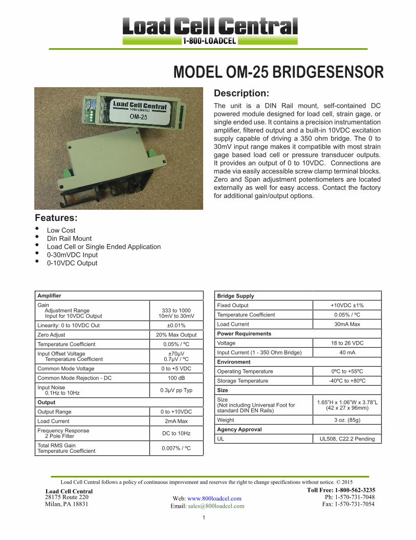
MODEL OM-25 BRIDGESENSORDescription:The unit is a DIN Rail mount, self-contained DC powered module designed for load cell, strain gage, or single ended use. It contains a precision instrumentation amplifier, filtered output and a built-in 10VDC excitation supply capable of driving a 350 ohm bridge. The 0 to 30mV input range makes it compatible with most strain gage based load cell or pressure transducer outputs. It provides an output of 0 to 10VDC. Connections are made via easily accessible screw clamp terminal blocks. Zero and Span adjustment potentiometers are located externally as well for easy access. Contact the factory for additional gain/output options.
Features:Low CostDin Rail MountLoad Cell or Single Ended Application0-30mVDC Input0-10VDC Output
•••••
AmplifierGain Adjustment Range Input for 10VDC Output
333 to �00010mV to 30mV
Linearity: 0 to 10VDC Out ±0.0�%
Zero Adjust 20% Max Output
Temperature Coefficient 0.05% / ºC
Input Offset Voltage Temperature Coefficient
±70µV0.7µV / ºC
Common Mode Voltage 0 to +5 VDC
Common Mode Rejection - DC �00 dB
Input Noise 0.�Hz to �0Hz 0.3µV pp Typ
OutputOutput Range 0 to +10VDC
Load Current 2mA Max
Frequency Response 2 Pole Filter DC to �0Hz
Total RMS GainTemperature Coefficient 0.007% / ºC
Bridge SupplyFixed Output +10VDC ±1%
Temperature Coefficient 0.05% / ºC
Load Current 30mA Max
Power RequirementsVoltage 18 to 26 VDC
Input Current (1 - 350 Ohm Bridge) 40 mA
EnvironmentOperating Temperature 0ºC to +55ºC
Storage Temperature -40ºC to +80ºC
SizeSize(Not including Universal Foot for standard DIN EN Rails)
�.65”H x �.06”W x 3.78”L(42 x 27 x 96mm)
Weight 3 oz. (85g)
Agency ApprovalUL UL508, C22.2 Pending
Toll Free: 1-800-562-323528175 Route 220 Ph: 1-570-731-7048Milan, PA 18831 Fax: 1-570-731-7054
Load Cell Central follows a policy of continuous improvement and reserves the right to change specifications without notice. © 2015
Load Cell Central Web: www.800loadcel.com
Email: [email protected]

2
MODEL OM-25 BRIDGESENSOR
Load Cell Central Å 28175 Route 220 Å Milan, PA 18831Toll Free: 1-800-562-3235 Å Fax: .1-570-731-7054
FULL BRIDGE CONNECTION
SINGLE ENDED
1. Hook Up Procedure A. Connect the +out of the load cell to the +INPUT, pin 4. B. Connect the -out of the load cell to the -INPUT, pin 3. C. Connect the +excitation of the load cell to +EXCITATION, pin �. D. Connect the -excitation of the load cell to -EXCITATION, pin 2. E. Connect the +24 VDC power supply to +24V, pin 8 and COM, pin 7.
2. Turn on Procedure A. Verify that the hook up procedure is complete. B. Turn on the +24 VDC power source connected to the 47�0.
3. Calibration Procedure A. Jumper the +INPUT and the -INPUT terminals, pins 3 and 4, together. B. Check the Gain Switch Table, and set SW1-1 and SW1-2 to the expected full scale output of the load cell.
Getting Started
SW1-1 SW1-2 FULL SCALE LOAD CELL INPUT
OFF OFF 30 mV
ON OFF 20 mV
ON ON 10 mV
C. Connect a voltmeter across the output, pins 5 and 6. D. Adjust the Zero Adjustment potentiometer for the desired output. E. Remove the jumper from the +INPUT and -INPUT terminals. F. With no load on the load cell, readjust the zero output. G. Apply a known load to the load cell; in most cases it would be 100% of full scale. H. Adjust the SPAN ADJUSTMENT potentiometer for the desired full scale output. I. Repeat steps F thru H until the desired settings are obtained.

3
MODEL OM-25 BRIDGESENSOR
Load Cell Central • 28175 Route 220 Å Milan, PA 18831Toll Free: 1-800-562-3235 Å Fax: 1-570-731-7054
TERMINAL FUNCTION
SW�-�, SW�-2 GAIN SWITCHES
SPAN SPAN ADJUSTMENT
� +EXCITATION
2 - EXCITATION
3 -INPUT
4 + INPUT
TERMINAL FUNCTION
5 + OUTPUT
6 COM
7 COM
8 +24V
ZERO ZERO ADJUSTMENT
Mechanical tolerances unless otherwise noted:
X.XX dimensions ±0.020 inchesX.XXX dimensions ±0.005 inches