model of low-thrust pulse detonation device with valveless ... · pdf filepulsed/continuous...
TRANSCRIPT
MODEL OF LOW-THRUST PULSE DETONATIONDEVICE WITH VALVELESS FUEL FEED
D. I. Baklanov, S. V. Golovastov, V.V. Golub,N.V. Semin, and V.V. Volodin
A model pulse detonation engine of low thrust is designed. A valvelessfuel and oxidant feed was used to ¦ll a combustion chamber. The deto-nation was formed in the §ow of mixed fuel and oxidant. The in§uenceof oxidant on the engine operation mode, the in§uence of ring obsta-cles and prechambers on de§agration-to-detonation transition (DDT),and the in§uence of fuel on engine output parameters were investigated.Air�hydrogen and air�hydrocarbon mixtures were used.
1 INTRODUCTION
Early attempts to utilize the power obtained from explosions for propulsion ap-plications date back to the late 17th � early 18th centuries, and the contributionsof Huygens and Allen are noteworthy. In 1729, Allen proposed a jet propelledship [1] ¤whose operation is owing to the explosion of gunpowder¥ in a properengine placed within a ship. Modern concepts of gaseous and heterogeneous det-onation applications for propulsion are described in the review of Roy et al. [2].In [3], multivalve pulse detonation device (PDD) with separate feeding of fuel
and oxidizer is suggested.At present, only laboratory PDDs operating on gaseous and liquid fuel with
air are developed [2, 4�6]. There are no reliable data on §ight tests whichis explained with a number of unsolved problems such as imperfect mixing offuel with air, nonuniform ¦lling of detonation chamber with detonable mixture,low detonability of fuel�air mixture, and high energy expenses on detonationignition.These disadvantages can be eliminated by the following ways: preliminary
fuel processing aimed at the increase of its detonability [7]; using of forecham-bers [4, 8]; cumulation of shock waves (SW) generated by ring discharge [9]or supersonic jets [10]; acceleration of initiating SW by successive electric dis-charges [11]; and installation of obstacles in detonation chamber [12�14].The most promising are the valveless PDDs [15]. Fuel and oxidizer supply
in such PDDs intermits with necessary frequency due to wave processes in feed
Progress in Propulsion Physics 1 (2009) 341-352 DOI: 10.1051/eucass/200901341 © Owned by the authors, published by EDP Sciences, 2009
This is an Open Access article distributed under the terms of the Creative Commons Attribution-Noncommercial License 3.0, which permits unrestricted use, distribution, and reproduction in any noncommercial medium, pro- vided the original work is properly cited.
Article available at http://www.eucass-proceedings.eu or http://dx.doi.org/10.1051/eucass/200901341
PROGRESS IN PROPULSION PHYSICS
manifolds. In general, the operation frequency depends on the length of det-onation chamber, its diameter, length of feed manifolds, their diameters, feedpressures, types of fuel and oxidizer, and equivalence ratio. A speci¦c feature ofa valveless PDD is the fact that ignition and detonation formation occur in theturbulent §ow of detonable mixture [16].
In the work of Smirnov et al. [17], a PDD for drilling purposes was presented.The device was fed with a carburated gasoline�air mixture from an automotiveengine. The mixture was ignited with an automotive spark plug.
In the paper of Frolov et al. [18], an air-breathing pulse detonation enginedemonstrator utilizing liquid fuel was described. It consists of two contours:The ¦rst contour serves for periodic detonation initiation in a fuel�air mixtureand detonation wave transitioning to the second contour. The detonation wavepassing the tube of the second contour is exhausted to the atmosphere throughthe nozzle, thus producing thrust. Air and fuel mass §ow rates in both con-tours; discharge current in spark plugs, and wave process dynamics were reg-istered during demonstrator operation. A powerful electric discharger, utilizedpreviously for generating primary SW, was replaced by a primary SW gener-ator comprising a relatively low-energy (50�60 J) electric discharger, Schelkinspiral, and tube coil. A second discharger was mounted at the exit of thetube coil and was activated in phase with the primary SW arrival at its po-sition during the cold start. Due to interactions between various wave sys-tems in the tube coil, formed at expansive and compressive surfaces, the to-tal critical energy of the detonation initiation, with two successively triggereddischargers, was decreased to about 100 J, i.e., by an order of magnitude, ascompared with the energy (∼ 1 kJ) required for the direct initiation of the n-hexane spray detonation in the straight 28-millimeter diameter smooth-walledtube, by a single electric discharger. The authors obtained periodic propagationof detonation waves in the combustion chambers of the engine demonstratorwith the frequency up to 8 Hz. It should be noted that the authors of Ref. [8]solved the fundamental task of detonating air suspensions of liquid hydrocarbondrops.
The aim of this investigation is design and testing of low-thrust PDD oper-ating on hydrogen or on the mixture of propane�butane with acetylene as thefuel and air as the oxidizer. The PDD does not contain valves for cutting-o¨ fueland oxidizer supply, and low-power ignition (automotive spark).
2 EXPERIMENTAL SETUPS
Valveless fuel and oxidant feed was used to ¦ll a cylindrical combustion chamber(CC) 2500 mm long and 22 mm in internal diameter (Fig. 1). The internaldiameter was twice larger than the detonation cell size in the stoichiometric
342

PULSED/CONTINUOUS DETONATION PROPULSION
Figure 1 Schematic of pulse detonation engine: 1, 5 ¡ fuel and oxidant feed man-ifolds; 2 ¡ spark plug; 3 ¡ combustion chamber; 4 ¡ detonation wave; 6 ¡ ringobstacle; 7 ¡ prechamber; and 8 ¡ nozzle
hydrogen�air mixture (λ ∼ 10 mm) and a factor of 3.5 larger than the detonationcell size in the stoichiometric acetylene�air mixture (λ ∼ 6 mm). The §owvelocity in the combustion chamber was 3�6 m/s at fuel consumption of 0.5�1 l/s. An electric discharge is used for detonation initiation. The detonation wasformed in the §ow of mixed fuel and oxidant.
The in§uence of oxidant on the operating mode of devices, the in§uence ofring obstacles and prechambers on DDT, and the in§uence of fuel on outputparameters of the devices were investigated.
At §ow velocity of 2 m/s, the predetonation distance in the stoichiometrichydrogen�air mixture was less than 14 tube diameters. The presence of ring ob-stacles (blockage ratio, BR = Aobstacle/Achannel = 0.75�0.94) and prechambers(expansion ratio, ER = Achamber/Achannel = 2.56) in the combustion chamberled to reduction of the predetonation distance in the stoichiometric hydrogen�air mixture more than by a factor of 2 (from more than 90 tube diametersto 45). The use of inhibited acetylene (90%C2H2 + 10%propane�butane) asfuel allowed reducing the predetonation distance to 30 tube diameters. The op-eration frequency of detonation devices was 1 Hz (for hydrogen) and 5 Hz (foracetylene).
Acetylene is known to be capable of decomposing with the formation of hy-drogen and carbon or methane accompanied with energy release and possibledetonation formation. So, acetylene containing fuel should be tested in terms ofexplosion safety. Acetylene decomposition is a complex chain-branching reaction.A lot of chemical mechanisms were suggested in the literature, e.g., [19�21]. Allof them include reactions with H (atomic hydrogen) radicals. The presence of Hradicals causes glow that may be detected with camera or photodetector. Thus,one can detect acetylene decomposition based on the presence of glow in themeasuring section. Test experiments with measuring glow intensity soot yieldindicated that the approach applied was su©ciently accurate for the purposes ofthe study.
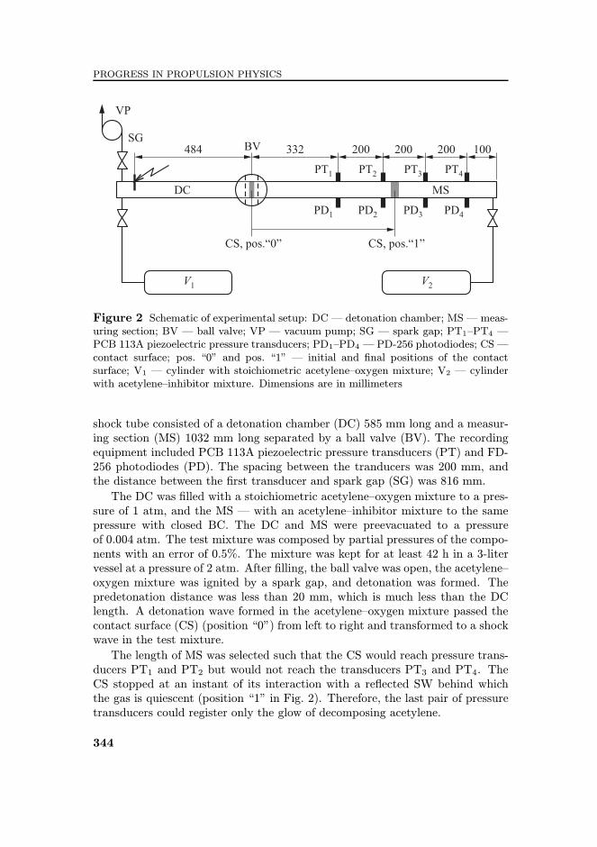
The experimental investigations were performed in a cylindrical shock tubeof an overall length of 1617 mm and inner diameter of 22 mm (Fig. 2). The
343
PROGRESS IN PROPULSION PHYSICS
Figure 2 Schematic of experimental setup: DC ¡ detonation chamber; MS ¡ meas-uring section; BV ¡ ball valve; VP ¡ vacuum pump; SG ¡ spark gap; PT1�PT4 ¡PCB 113A piezoelectric pressure transducers; PD1�PD4 ¡ PD-256 photodiodes; CS ¡contact surface; pos. ¤0¥ and pos. ¤1¥ ¡ initial and ¦nal positions of the contactsurface; V1 ¡ cylinder with stoichiometric acetylene�oxygen mixture; V2 ¡ cylinderwith acetylene�inhibitor mixture. Dimensions are in millimeters
shock tube consisted of a detonation chamber (DC) 585 mm long and a measur-ing section (MS) 1032 mm long separated by a ball valve (BV). The recordingequipment included PCB 113A piezoelectric pressure transducers (PT) and FD-256 photodiodes (PD). The spacing between the tranducers was 200 mm, andthe distance between the ¦rst transducer and spark gap (SG) was 816 mm.
The DC was ¦lled with a stoichiometric acetylene�oxygen mixture to a pres-sure of 1 atm, and the MS ¡ with an acetylene�inhibitor mixture to the samepressure with closed BC. The DC and MS were preevacuated to a pressureof 0.004 atm. The test mixture was composed by partial pressures of the compo-nents with an error of 0.5%. The mixture was kept for at least 42 h in a 3-litervessel at a pressure of 2 atm. After ¦lling, the ball valve was open, the acetylene�oxygen mixture was ignited by a spark gap, and detonation was formed. Thepredetonation distance was less than 20 mm, which is much less than the DClength. A detonation wave formed in the acetylene�oxygen mixture passed thecontact surface (CS) (position ¤0¥) from left to right and transformed to a shockwave in the test mixture.
The length of MS was selected such that the CS would reach pressure trans-ducers PT1 and PT2 but would not reach the transducers PT3 and PT4. TheCS stopped at an instant of its interaction with a re§ected SW behind whichthe gas is quiescent (position ¤1¥ in Fig. 2). Therefore, the last pair of pressuretransducers could register only the glow of decomposing acetylene.
344
PULSED/CONTINUOUS DETONATION PROPULSION
3 RESULTS
3.1 Acetylene Phlegmatization
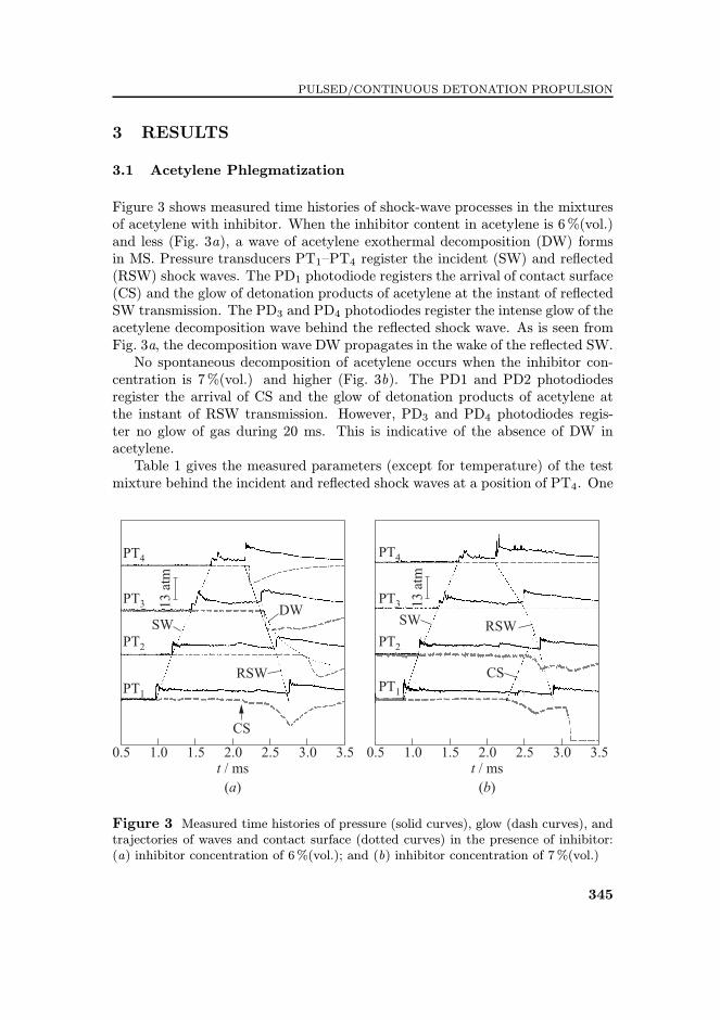
Figure 3 shows measured time histories of shock-wave processes in the mixturesof acetylene with inhibitor. When the inhibitor content in acetylene is 6%(vol.)and less (Fig. 3a), a wave of acetylene exothermal decomposition (DW) formsin MS. Pressure transducers PT1�PT4 register the incident (SW) and re§ected(RSW) shock waves. The PD1 photodiode registers the arrival of contact surface(CS) and the glow of detonation products of acetylene at the instant of re§ectedSW transmission. The PD3 and PD4 photodiodes register the intense glow of theacetylene decomposition wave behind the re§ected shock wave. As is seen fromFig. 3a, the decomposition wave DW propagates in the wake of the re§ected SW.No spontaneous decomposition of acetylene occurs when the inhibitor con-
centration is 7%(vol.) and higher (Fig. 3b). The PD1 and PD2 photodiodesregister the arrival of CS and the glow of detonation products of acetylene atthe instant of RSW transmission. However, PD3 and PD4 photodiodes regis-ter no glow of gas during 20 ms. This is indicative of the absence of DW inacetylene.Table 1 gives the measured parameters (except for temperature) of the test
mixture behind the incident and re§ected shock waves at a position of PT4. One
Figure 3 Measured time histories of pressure (solid curves), glow (dash curves), andtrajectories of waves and contact surface (dotted curves) in the presence of inhibitor:(a) inhibitor concentration of 6%(vol.); and (b) inhibitor concentration of 7%(vol.)
345

PROGRESS IN PROPULSION PHYSICS
Table 1 Parameters of unreacted gas behind the incident and re§ected shock wavesat the position of PT4: Cinh ¡ concentration of inhibitor in acetylene; MSW ¡ Machnumber of incident SW; PSW ¡ pressure at the SW front; TSW ¡ temperature at theSW front; PRSW ¡ pressure in the RSW front; and TRSW ¡ temperature in the RSWfront
Cinh,%
MSW PSW, atm TSW, KPRSW,atm
TRSW, K
0 2.18± 0.12 5.4 ± 0.6 530 ± 29 11.8 ± 3.2 819 ± 662.5 2.44± 0.05 6.8 ± 0.3 598 ± 18 16.1 ± 4.5 973 ± 295 2.34± 0.09 6.2 ± 0.5 570 ± 23 14.2 ± 2.2 911 ± 51 Decomposition
6 2.14± 0.07 5.2 ± 0.4 551 ± 18 10.7 ± 2.3 796 ± 53
7 2.06± 0.06 4.8 ± 0.3 532 ± 21 9.5± 1.9 752 ± 4810 2.24± 0.09 5.7 ± 0.4 540 ± 19 12.2 ± 0.7 842 ± 52 No decomposition25 2.02 4.6 481 8.1 709
can see that the pressure behind the RSW increases as high as 13 to 20 atm,and the temperature attains the values as high as 800 to 1000 K. In all cases,except for the case of inhibitor concentration of 25%(vol.), the conditions of theacetylene�inhibitor mixture behind the re§ected and incident SWs were identical.Therefore, one can belive that the obtained results are correct.
3.2 Testing of Valveless Pulse Detonation Device
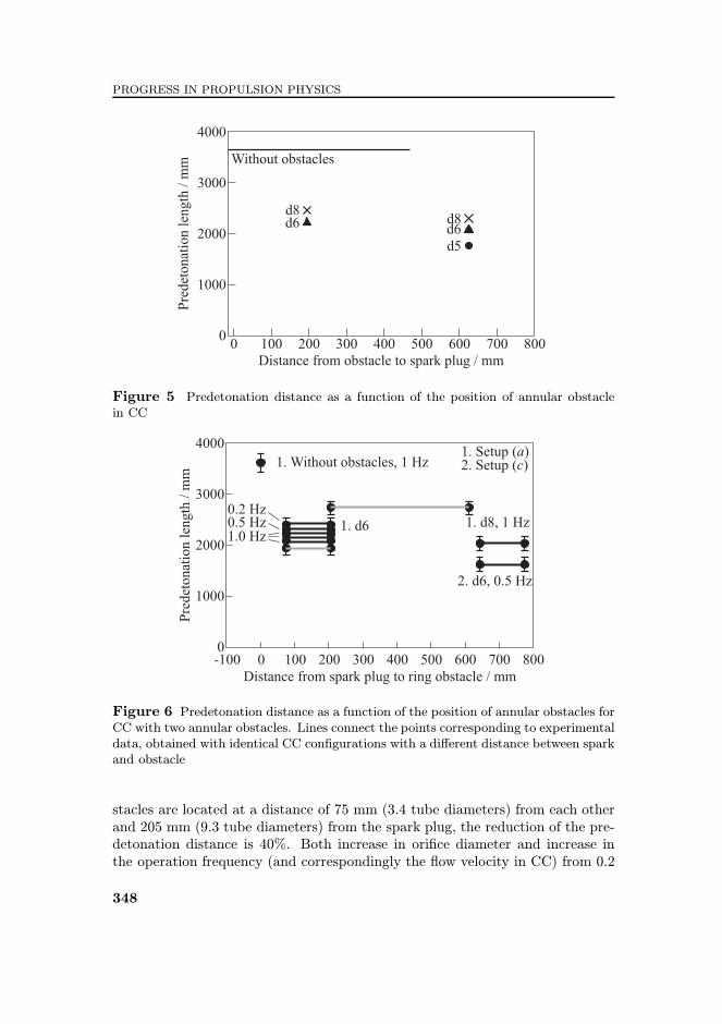
Three di¨erent con¦gurations of the CC shown in Fig. 4 were used to studythe in§uence of the CC shape on detonation parameters. In di¨erent experi-ments, one or two annular ring obstacles with ori¦ce diameter ranging from 5to 10 mm (blockage ratio 0.75�0.94) and/or precombustion chamber (tube sec-tion 620 mm long, Fig. 4b) were installed in the CC. A series of experiments inthe CC of variable diameter (Fig. 4c) was also carried out. The arrangementof annular obstacles along the tube was varied to ¦nd the most advantageousarrangement.The use of annular obstacles and precombustion chambers made it possible
to reduce the predetonation distance to less than hundred tube diameters. It isevident from Fig. 5 that the presence of a single annular obstacle in the tube ofconstant diameter causes re§ection of SW, formation of hot jet of combustionproducts, and detonation initiation. The classical initiation mechanism of det-onation with SW re§ection followed by di¨raction of the formed detonation inthe opening is not applied in this case because of the small chamber diameter(∼ 2 detonation cells) and very small ori¦ce diameter in the obstacle (∼ 1/3 ofdetonation cell). This process reduces the predetonation distance by a factor
346

PULSED/CONTINUOUS DETONATION PROPULSION
Figure 4 Combustion chambers tested in the experiments: (a) with annular obstacles(AO); (b) with precombustion chamber and AO; and (c) with variable cross-sectionarea. Dimensions are in millimeters
of 1.5. Decreasing ori¦ce diameter and increasing the distance between the ob-stacle and the spark lead to further reduction of the predetonation distance thatcon¦rms the jet mechanism of detonation initiation.
In Fig. 6, the predetonation distances in the CC with two annular obstaclesare presented. In the tube of constant cross section, a strong dependence ofthe predetonation distance on the position of obstacles is observed: two annularobstacles with ori¦ce diameter 8 mm, located at a distance of 205 mm (9.3 tubediameters) and 610 mm (27.7 tube diameters) from the spark plug reduce thepredetonation distance by 20% as compared with the smooth tube. If the ob-
347
PROGRESS IN PROPULSION PHYSICS
Figure 5 Predetonation distance as a function of the position of annular obstaclein CC
Figure 6 Predetonation distance as a function of the position of annular obstacles forCC with two annular obstacles. Lines connect the points corresponding to experimentaldata, obtained with identical CC con¦gurations with a di¨erent distance between sparkand obstacle
stacles are located at a distance of 75 mm (3.4 tube diameters) from each otherand 205 mm (9.3 tube diameters) from the spark plug, the reduction of the pre-detonation distance is 40%. Both increase in ori¦ce diameter and increase inthe operation frequency (and correspondingly the §ow velocity in CC) from 0.2
348
PULSED/CONTINUOUS DETONATION PROPULSION
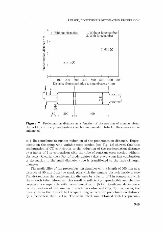
Figure 7 Predetonation distance as a function of the position of annular obsta-cles in CC with the precombustion chamber and annular obstacle. Dimensions are inmillimeters
to 1 Hz contribute to further reduction of the predetonation distance. Exper-iments on the setup with variable cross section (see Fig. 4c) showed that thiscon¦guration of CC contributes to the reduction of the predetonation distanceby a factor of 2 in comparison with the tube of constant cross section withoutobstacles. Clearly, the e¨ect of predetonator takes place when fast combustionor detonation in the small-diameter tube is transitioned to the tube of largerdiameter.The availability of the precombustion chamber with a length of 600 mm at a
distance of 80 mm from the spark plug with the annular obstacle inside it (seeFig. 4b) reduces the predetonation distance by a factor of 3 in comparison withthe smooth tube. Moreover, this result is su©ciently reproducible and the dis-crepancy is comparable with measurement error (5%). Signi¦cant dependenceon the position of the annular obstacle was observed (Fig. 7): increasing thedistance from the obstacle to the spark plug reduces the predetonation distanceby a factor less than ∼ 1.5. The same e¨ect was obtained with the precom-
349

PROGRESS IN PROPULSION PHYSICS
bustion chamber of smaller length with the ori¦ce of smaller diameter. Whencomparing these results with the data of other researchers obtained for the in-itially quiescent mixture, one comes to a conclusion that they agree with eachother qualitatively.
In the experiments, acetylene inhibited by propane�butane mixture(90%C2H2 + 10%propane�butane) was also used as fuel. This led to the de-crease of the predetonation distance to 30 tube diameters which can be explainedby higher detonability of acetylene�air mixture.
In pulse detonation mode, the setup was operated with two oxidizers, oxy-gen and air. At frequencies above 0.5 Hz, the use of oxygen as the oxidizer wasprohibited due to excessive heating of CC resulting in transition of cyclic detona-tion mode to the intermittent combustion mode of setup operation. Therefore,at frequencies above 0.5 Hz, air was used as an oxidizer.
Thrust measurements were also made for estimating the propulsive e©ciencyof the detonation process. Thrust measurements were conducted using the in-stallation of Fig. 4c with hydrogen and inhibited acetylene as fuels. For bothtypes of fuel, the maximum measured thrust value was identical and equal to 50 gat a frequency of 1 Hz.
4 CONCLUDING REMARKS
Three PDD combustion chamber designs were investigated, all operating on astoichiometric hydrogen�air mixture. The use of precombustion chamber withannular obstacles was shown to reduce the DDT length.
Acetylene-containing mixtures were also considered as a possible PDD fuel.Acetylene was inhibited by a gas (propane�butane) that is a fuel per se. Theminimal concentration of inhibitor has been experimentally determined, at whichno spontaneous decomposition of acetylene occurred behind RSW. This minimalconcentration was 7%(vol.). The data obtained can be employed for storage andtransportation of acetylene in undissolved state.
The regimes of cyclic detonation initiation in acetylene and hydrogen mix-tures with oxygen and air were obtained experimentally. The thrust created bydetonations was measured. The in§uence of tube geometry on the formation ofdetonation was evaluated.
ACKNOWLEDGMENTS
This work was supported ¦nancially by the Russian Academy of Sciences Pre-sidium Programs (P-9 and DE-1) and performed under the contract to the In-ternational Science and Technology Center (ISTC), Moscow.
350

PULSED/CONTINUOUS DETONATION PROPULSION
REFERENCES
1. Lyle Cummins JrC. 1976. Internal ¦re. Lake Oswego, Oregon: Carnot Press.
2. Roy, G.D., S.M. Frolov, A.A. Borisov, and D.W. Netzer. 2004. Pulse detona-tion propulsion: Challenges, current status, and future perspective. Prog. EnergyCombust. Sci. 30(6):545�672.
3. Hunter. L.G., G. Louis, and D.D. Winfree. 1996. U.S. Patent No. 5,557,926. Pri-ority 24.09.96.
4. Brophy, C.M., D.W. Netzer, J. Sinibaldi, and R. Johnson. 2001. Detonation ofJP-10 aerosol for pulse detonation applications. In: High-speed de§agration anddetonation: Fundamentals and control. Eds. G. Roy, S. Frolov, D. Netzer, andA. Borisov. Moscow: ELEX-KM Publ. 207�22.
5. Baklanov, D. I., L.G. Gvozdeva, and N.B. Sherbak. 2001. Pulsed detonation com-bustion chamber for PDE. In: High-speed de§agration and detonation: Funda-mentals and control. Eds. G. Roy, S. Frolov, D. Netzer, and A. Borisov. Moscow:ELEX-KM Publ. 239�50.
6. Shauer, F., J. Stutrud, R. Bradley, V. Katta, and J. Hoke. 2003. Detonation stud-ies and performance results for a research pulse detonation engine. In: Con¦neddetonations and pulse detonation engines. Eds. G. Roy, S. Frolov, R. Santoro, andS. Tsyganov. Moscow: TORUS PRESS. 287�302.
7. Levin, V.A., J.N. Nechaev, and A. I. Tarasov. 2001. A new approach to organ-izing operation cycles in pulsed detonation engines. In: High-speed de§agrationand detonation: Fundamentals and control. Eds. G. Roy, S. Frolov, D. Netzer, andA. Borisov. Moscow: ELEX-KM Publ. 223�38.
8. Murray, S. B., P.A. Thibault, F. Zhang, D. Bjerketvedt, A. Sulmistras,G.O. Thomas, A. Jenssen, and I.O. Moen. 2001. The role of energy distribution onthe transmissiun of detonation. In: High-speed de§agration and detonation: Fun-damentals and control. Eds. G. Roy, S. Frolov, D. Netzer, and A. Borisov. Moscow:ELEX-KM Publ 139�62.
9. Korobeinikov, V.P., V.V. Markov, I. V. Semenov, P.D. Pedrow, and S. Wojcicki.2001. Electrochemical pulse detonation engine. In: High-speed de§agration anddetonation: Fundamentals and control. Eds. G. Roy, S. Frolov, D. Netzer, andA. Borisov. Moscow: ELEX-KM Publ. 289�302.
10. Achasov, O.V., and O.G. Penyazkov. 2001. Some gasdynamic methods for controlof detonation initiation and propagation. In: High-speed de§agration and detona-tion: Fundamentals and control. Eds. G. Roy, S. Frolov, D. Netzer, and A. Borisov.Moscow: ELEX-KM Publ. 31�44.
11. Frolov, S.M., V.Ya. Basevich, V. S. Aksenov, and S.A. Polichov. 2002. Initiationof spray detonation by successive triggering of electric discharges. In: Advancesof con¦ned detonations. Eds. G. Roy, S. Frolov, R. Santoro, and S. Tsyganov.Moscow: TORUS PRESS. 150�57.
12. Smirnov, N.N., V. F. Nikitin, M.V. Tyurnikov, A.P. Boichenko, J. C. Legros,and V.M. Shevtsova. 2001. Control of detonation onset in combustible gases. In:High-speed de§agration and detonation: Fundamentals and control. Eds. G. Roy,S. Frolov, D. Netzer, and A. Borisov. Moscow: ELEX-KM Publ. 3�30.
351

PROGRESS IN PROPULSION PHYSICS
13. Higgins, A. J., P. Pinard, A.C. Yoshinaka, and J.H. S. Lee. 2001. Sensitizationof fuel-air mixtures for de§agration-to-detonation transition. In: High-speed defla-gration and detonation: Fundamentals and control. Eds. G. Roy, S. Frolov, D. Net-zer, and A. Borisov. Moscow: ELEX-KM Publ. 45�62.
14. Semenov, I., S. Frolov, V. Markov, and P. Utkin. 2006. Shock-to-detonation tran-sition in tubes with shaped obstacles. In: Pulsed and continuous detonations. Eds.G. Roy, S. Frolov, and J. Sinibaldi. Moscow: TORUS PRESS. 159�69.
15. Baklanov, D. I., D.G. Zhimerin, Ju. N. Kiselev, E. L. Mironov, and V.A. Popov.1976. On some technical aspects of detonation regime of combustiom using. Com-bust. Explosion Shock Waves 12(1):47�52.
16. Baklanov, D. I., S.V. Golovastov, V.V. Golub, and V.V. Volodin. 2004. Detona-tion formation in moving detonable mixture §ow. In: Application of detonation topropulsion. Eds. G. Roy, S. Frolov, and J. Shepherd. Moscow: TORUS PRESS.225�31.
17. Smirnov, N.N., V.F. Nikitin, A.P. Boichenko, M.V. Tyurnikov, and V.V. Baska-kov. 1999. Control of de§agration to detonation transition in gases and its appli-cation to pulsed detonation devices. In: Gaseous and heterogeneous detonations:Science to applications. Eds. G. Roy, S. Frolov, K. Kailasanath, and N. Smirnov.Moscow: ENAS Publ. 65�94.
18. Frolov, S.M., V. S. Aksenov, and V.Ya. Basevich. 2005. Air-breathing liquid-fueled pulse detonation engine demonstrator. Doklady Physical Chemistry402(part 4):93�95.
19. Tanzawa, T., and W.C. Gardiner. 1980. Reaction mechanism of the homogeneousthermal decomposition of acetylene. J. Phys. Chem. 84(3):236�39.
20. Clary, D., M. Frenklach, W. Gardiner, and St. Stein. 1984. Detailed kinetic mod-eling of soot formation in shock-tube pyrolysis of acetylene. 20th Symposium (In-ternational) on Combustion Proceedings. The Combustion Institute. 887�901.
21. Krestinin, A.V. 1994. About mechanism of soot-formation from acetylene. Chem.Phys. Rep. 13(1):121�31.
352