model-driven user interface generation and adaptation in...
TRANSCRIPT
Model-Driven User InterfaceGeneration and Adaptation in
Process-Aware Information Systems
Jens Kolb, Paul Hubner and Manfred Reichert
Institute of Databases and Information SystemsUlm University, Germany
{jens.kolb,paul.huebner,manfred.reichert}@uni-ulm.de
http://www.uni-ulm.de/dbis
Abstract. The increasing adoption of process-aware information sys-tems (PAISs) has resulted in a large number of implemented business pro-cesses. To react on changing needs, companies should be able to quicklyadapt these process implementations if required. Current PAISs, how-ever, only provide mechanisms to evolve the schema of a process model,but do not allow for the automated creation and adaptation of their userinterfaces (UIs). The latter may have a complex logic and comprise, forexample, conditional elements or database queries. Creating and evolv-ing the UI components of a PAIS manually is a tedious and error-pronetask. This technical report introduces a set of patterns for transformingfragments of a business process model, whose activities are performedby the same user role, to UI components of the PAIS. In particular, UIlogic can be expressed using the same notation as for process modeling.Furthermore, a transformation method is introduced, which applies thesepatterns to automatically derive UI components from a process modelby establishing a bidirectional mapping between process model and UI.This mapping allows propagating UI changes to the process model andvice versa. Overall, our approach enables process designers to rapidlydevelop and update complex UI components in PAISs.
1 Introduction
Process-aware information systems (PAISs) separate process execution from ap-plication code, i.e., the implementation of process activities. Hence, separationof concerns, which is a well-established principle in computer science is realizedbased on explicit process models. When initially capturing business processes inprocess models, focus is put on business aspects, while technical aspects concern-ing later process execution are excluded. Usually, the resulting business processmodels cover the users’ activities at a fine-grained level (cf. Figure 1a). Hence,before deploying such a business process model in the PAIS, therefore, it mustbe revised and customized. For example, several human tasks, forming a pro-cess fragment in the business process model, may have to be combined into oneactivity in the executable process model (cf. Figure 1b). This activity is then

2 Jens Kolb, Paul Hubner and Manfred Reichert
implemented by a respective user interface (UI) component in the PAIS, e.g.,a user form whose corresponds to the one of the initial process fragment (cf.Figure 1c). Based on such a logic, for example, form elements may be disabledwhen selecting a certain check box, or database queries or web services may berun in the background to fetch or save data. Overall, both the implementationand maintenance of the UI components in a PAIS is a cumbersome and costlytask. In particular, this hinders quick adaptations of process implementations[1].
Select
Customer
Choose
Contact
Type
Edit
AddressReview
Account
Accept
Message
Decline
Message
Create
Customer
Clerk
Clerk
Clerk
Clerk
Manager
Manager
Manager Approve
Account Clerk Manager
Edit
Customer
CustId:int
Approve Account: Man...
Edit Customer: Clerk UI
Choose Contact Type
Edit Address
Street
City
E-MailContact
a) Initial (Business) Process Model b) Executable Process Model c) User Interface Components
Activity
XOR
AND
Data Element SESE block
(Single Entry Single Exit)
Fig. 1. Deriving UI Components from a Business Process Model
The proper evolution of the processes implemented in a PAIS is a criticalsuccess factor for any company [2]. It not only requires changes of the processmodels, but of the associated UI components and their internal logic as well(e.g., adding new input fields). Process model evolution is a well-understood fea-ture in modern PAIS [3,4]. There exist editors for defining and changing simpleUI components of the PAISs (e.g., moving or renaming input fields in a userform). However, complex changes of the internal logic of user forms can not beaccomplished by users, but require process implementers to intervene. Moreover,the automatic propagation of changes made in the UI components to businessprocess model and vice versa is not supported.This paper addresses these issues through the automatic generation of com-plex UI components out of process model fragments. In this context, we firstpresent common patterns for transforming process fragments to UI components.Thereby, we distinguish between elementary and complex transformations. Whileelementary transformation patterns (ETP) transform single activities of a pro-cess model to simple UI elements, complex transformation patterns (CTP) enablethe mapping of entire process fragments and their logic to UI components, show-ing the same behaviour as the original process fragment does. Additionally, weprovide an advanced transformation method for business process models thatallows generating sophisticated UI components out of these models based on theuser roles assigned to process activities. This method further allows propagatingchanges of UI components to the corresponding process model and vice versa.Especially, for human-centric processes, our transformation method decreasesthe effort for evolving PAIS to accommodate to changing needs.The paper is structured as follows: Section 2 introduces basic notions. Section3 describes common patterns for transforming process model fragments to UIcomponents. Section 4 then presents a method for transforming process models
Automatic User Interface Generation 3
to a set of UI components. This method is based on transformation patternsand role-based process views. Section 5 sketches our proof-of-concept prototype.Section 6 discusses related work and Section 7 summarizes the paper.
2 Basic Notions
A process model is described in terms of a directed graph whose node set com-prises activities, gateways, and data elements. An activity either corresponds toa human task and thus requires user interactions, or to a service representingan automated task. In turn, gateways can be categorized into AND, XOR andLoop and are used for modeling parallel/conditional branchings and loop struc-tures. Edges between activities and/or gateways represent precedence relations,i.e., the control flow of the process model (cf. Figure 1a). Furthermore, dataelements comprise primitive data elements and complex ones. Primitive dataelements cover elementary data values of the process model and have one of thefollowing types: integer, float, boolean, string, date, or URI. In turn, complexdata elements compose primitive and/or complex data elements. Based on this,the data flow is defined by a set of directed edges connecting data elements andactivities. Writing a data element is expressed through an edge pointing from anactivity to the data element. In turn, reading a data element is expressed throughan edge from this data element to the activity. We presume that process modelsare well-structured [5,6], i.e., sequences, branchings (of different semantics), andloops are specified as blocks with well-defined start and end nodes having thesame gateway type. These blocks, also known as SESE (single-entry-single-exit)blocks, may be nested, but are not allowed to overlap (cf. Figure 1a).
3 User Interface Transformation Patterns
This section introduces a set of well-elaborated patterns for transforming a pro-cess fragment to a corresponding UI component. Section 3.1 discusses how weidentified these UI transformation patterns. Section 3.2 then introduces Elemen-tary Transformation Patterns (ETP), which constitute the basis for the ComplexTransformation Patterns (CTP) presented in Section 3.3.
3.1 Pattern Identification
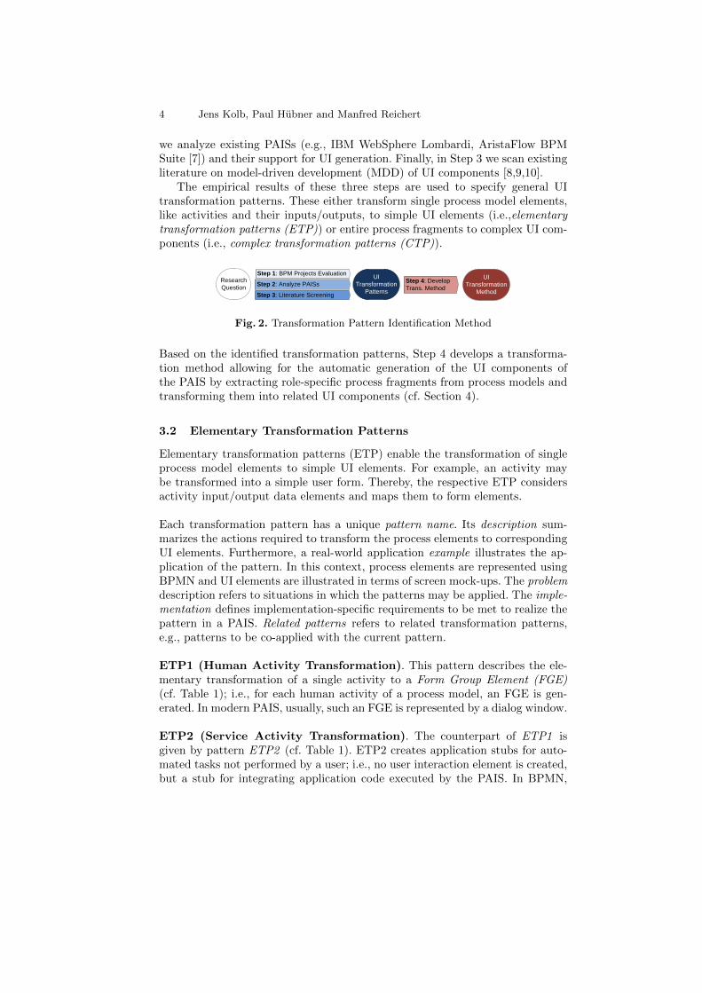
The goal of our research is to identify and apply a general set of UI transfor-mation patterns, which allow mapping process fragments to UI components. Toachieve this goal, we first describe a three-step method, which we apply for iden-tifying relevant UI transformation patterns (cf. Figure 2). In Step 1, we analyzeand evaluate PAIS engineering projects in which we were involved in the past.More precisely, we analyze the business process models from these projects aswell as their technical implementation and related UI components. In Step 2,
4 Jens Kolb, Paul Hubner and Manfred Reichert
we analyze existing PAISs (e.g., IBM WebSphere Lombardi, AristaFlow BPMSuite [7]) and their support for UI generation. Finally, in Step 3 we scan existingliterature on model-driven development (MDD) of UI components [8,9,10].
The empirical results of these three steps are used to specify general UItransformation patterns. These either transform single process model elements,like activities and their inputs/outputs, to simple UI elements (i.e.,elementarytransformation patterns (ETP)) or entire process fragments to complex UI com-ponents (i.e., complex transformation patterns (CTP)).
UI
Transformation
Patterns
Research
Question
UI
Transformation
Method
Step 2: Analyze PAISs
Step 1: BPM Projects Evaluation
Step 3: Literature Screening
Step 4: Develop
Trans. Method
Fig. 2. Transformation Pattern Identification Method
Based on the identified transformation patterns, Step 4 develops a transforma-tion method allowing for the automatic generation of the UI components ofthe PAIS by extracting role-specific process fragments from process models andtransforming them into related UI components (cf. Section 4).
3.2 Elementary Transformation Patterns
Elementary transformation patterns (ETP) enable the transformation of singleprocess model elements to simple UI elements. For example, an activity maybe transformed into a simple user form. Thereby, the respective ETP considersactivity input/output data elements and maps them to form elements.
Each transformation pattern has a unique pattern name. Its description sum-marizes the actions required to transform the process elements to correspondingUI elements. Furthermore, a real-world application example illustrates the ap-plication of the pattern. In this context, process elements are represented usingBPMN and UI elements are illustrated in terms of screen mock-ups. The problemdescription refers to situations in which the patterns may be applied. The imple-mentation defines implementation-specific requirements to be met to realize thepattern in a PAIS. Related patterns refers to related transformation patterns,e.g., patterns to be co-applied with the current pattern.
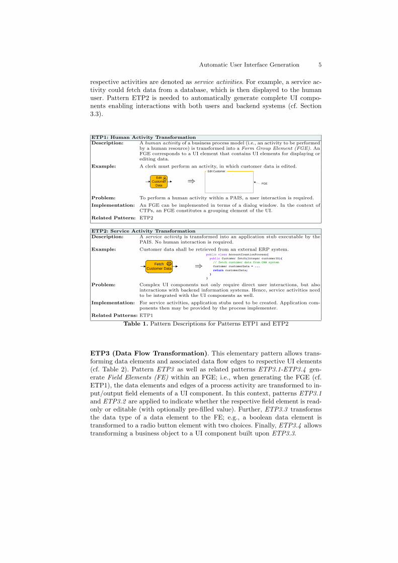
ETP1 (Human Activity Transformation). This pattern describes the ele-mentary transformation of a single activity to a Form Group Element (FGE)(cf. Table 1); i.e., for each human activity of a process model, an FGE is gen-erated. In modern PAIS, usually, such an FGE is represented by a dialog window.
ETP2 (Service Activity Transformation). The counterpart of ETP1 isgiven by pattern ETP2 (cf. Table 1). ETP2 creates application stubs for auto-mated tasks not performed by a user; i.e., no user interaction element is created,but a stub for integrating application code executed by the PAIS. In BPMN,
Automatic User Interface Generation 5
respective activities are denoted as service activities. For example, a service ac-tivity could fetch data from a database, which is then displayed to the humanuser. Pattern ETP2 is needed to automatically generate complete UI compo-nents enabling interactions with both users and backend systems (cf. Section3.3).
ETP1: Human Activity TransformationDescription: A human activity of a business process model (i.e., an activity to be performed
by a human resource) is transformed into a Form Group Element (FGE). AnFGE corresponds to a UI element that contains UI elements for displaying orediting data.
Example: A clerk must perform an activity, in which customer data is edited.
Edit
Customer
Data⇒
Edit Customer
FGE
Problem: To perform a human activity within a PAIS, a user interaction is required.
Implementation: An FGE can be implemented in terms of a dialog window. In the context ofCTPs, an FGE constitutes a grouping element of the UI.
Related Pattern: ETP2
ETP2: Service Activity TransformationDescription: A service activity is transformed into an application stub executable by the
PAIS. No human interaction is required.
Example: Customer data shall be retrieved from an external ERP system.
Fetch
Customer Data ⇒public class AccountCreationProcess{
public Customer fetch(Integer customerID){
// fetch customer data from CRM system
Customer customerData = ...
return customerData;
}
}
Problem: Complex UI components not only require direct user interactions, but alsointeractions with backend information systems. Hence, service activities needto be integrated with the UI components as well.
Implementation: For service activities, application stubs need to be created. Application com-ponents then may be provided by the process implementer.
Related Patterns: ETP1
Table 1. Pattern Descriptions for Patterns ETP1 and ETP2
ETP3 (Data Flow Transformation). This elementary pattern allows trans-forming data elements and associated data flow edges to respective UI elements(cf. Table 2). Pattern ETP3 as well as related patterns ETP3.1-ETP3.4 gen-erate Field Elements (FE) within an FGE; i.e., when generating the FGE (cf.ETP1), the data elements and edges of a process activity are transformed to in-put/output field elements of a UI component. In this context, patterns ETP3.1and ETP3.2 are applied to indicate whether the respective field element is read-only or editable (with optionally pre-filled value). Further, ETP3.3 transformsthe data type of a data element to the FE; e.g., a boolean data element istransformed to a radio button element with two choices. Finally, ETP3.4 allowstransforming a business object to a UI component built upon ETP3.3.
6 Jens Kolb, Paul Hubner and Manfred Reichert
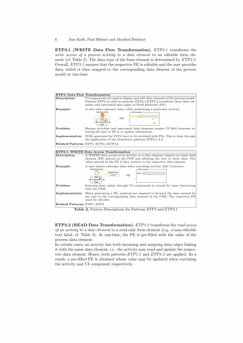
ETP3.1 (WRITE Data Flow Transformation). ETP3.1 transforms thewrite access of a process activity to a data element to an editable form ele-ment (cf. Table 2). The data type of the form element is determined by ETP3.3.Overall, ETP3.1 ensures that the respective FE is editable and the user providesdata, which is then mapped to the corresponding data element of the processmodel at run-time.
ETP3: Data Flow TransformationDescription: UI components are used to display and edit data elements of the process model.
Pattern ETP3 as well as patterns ETP3.1-ETP3.4 transform these data ele-ments and associated data edges to Field Elements (FE).
Example: A user edits customer data, while performing a particular activity.
Edit
Customer
Data
DataType:Name
⇒Edit Customer
Name: DataType-specific Field Elem.
FE
Problem: Human activities and associated data elements require UI field elements al-lowing the user to fill in or update information.
Implementation: FGEs generated by ETP1 have to be enriched with FEs. This is done throughthe application of the elementary patterns ETP3.1-3.4.
Related Patterns: ETP1, ETP3.1-ETP3.4
ETP3.1: WRITE Data Access TransformationDescription: A WRITE data access of an activity to a data element requires an input field
element (FE) placed on the FGE and allowing the user to enter data. Thevalue entered in the FE is then written to the respective data element.
Example: A user inserts customer data when executing activity Edit Customer.
Edit
Customer
Data
DataType:Name
WRITE Data
Access ⇒Edit Customer
Name: DataType-specific Input Field
Problem: Inserting data values through UI components is crucial for users interactingwith the PAIS.
Implementation: When generating a FE, methods are required to forward the data entered bythe user to the corresponding data element in the PAIS. The respective FEmust be editable.
Related Patterns: ETP1, ETP3
Table 2. Pattern Descriptions for Patterns ETP3 and ETP3.1
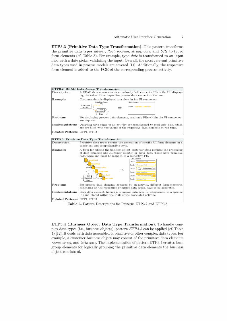
ETP3.2 (READ Data Transformation). ETP3.2 transforms the read accessof an activity to a data element to a read-only form element (e.g., a non-editabletext label, cf. Table 3). At run-time, the FE is pre-filled with the value of theprocess data element.In certain cases, an activity has both incoming and outgoing data edges linkingit with the same data element; i.e., the activity may read and update the respec-tive data element. Hence, both patterns ETP3.1 and ETP3.2 are applied. As aresult, a pre-filled FE is obtained whose value may be updated when executingthe activity and UI component respectively.
Automatic User Interface Generation 7
ETP3.3 (Primitive Data Type Transformation). This pattern transformsthe primitive data types integer, float, boolean, string, date, and URI to typedform elements (cf. Table 3). For example, type date is transformed to an inputfield with a date picker validating the input. Overall, the most relevant primitivedata types used in process models are covered [11]. Additionally, the respectiveform element is added to the FGE of the corresponding process activity.
ETP3.2: READ Data Access TransformationDescription: A READ data access creates a read-only field element (FE) in the UI, display-
ing the value of the respective process data element to the user.
Example: Customer data is displayed to a clerk in his UI component.
Edit
Customer
Data
DataType:Name
READ Data
Access ⇒Edit Customer
Name: Read-only Label Field
Problem: For displaying process data elements, read-only FEs within the UI componentare required.
Implementation: Outgoing data edges of an activity are transformed to read-only FEs, whichare pre-filled with the values of the respective data elements at run-time.
Related Patterns: ETP1, ETP3
ETP3.3: Primitive Data Type TransformationDescription: Primitive data types require the generation of specific UI form elements in a
consistent and comprehensible style.
Example: A form for editing the business object customer data requires the processingof data elements like customer number or birth date. These have primitivedata types and must be mapped to a respective FE.
URI:Data6
Date:Data5
Float:Data2
Integer:Data1
Boolean:Data3
String:Data4
Edit
Customer
Data
⇒
Edit Customer
Integer Input FieldData1:
Float Input FieldData2:
false
trueData3:
String Input FieldData4:
M
May 12
T W T F S S
1 2 3 4 5 6
7 8 910
11
12
131
415
16
17
18
19
202
122
23
24
25
26
272
829
30
31
Date-Time Input FieldData5:
URI Input FieldData6:
Boolean Input Field
Problem: For process data elements accessed by an activity, different form elements,depending on the respective primitive data types, have to be generated.
Implementation: Each data element, having a primitive data type, is transformed to a specificFE and placed within the FGE of the associated activity.
Related Patterns: ETP1, ETP3
Table 3. Pattern Descriptions for Patterns ETP3.2 and ETP3.3
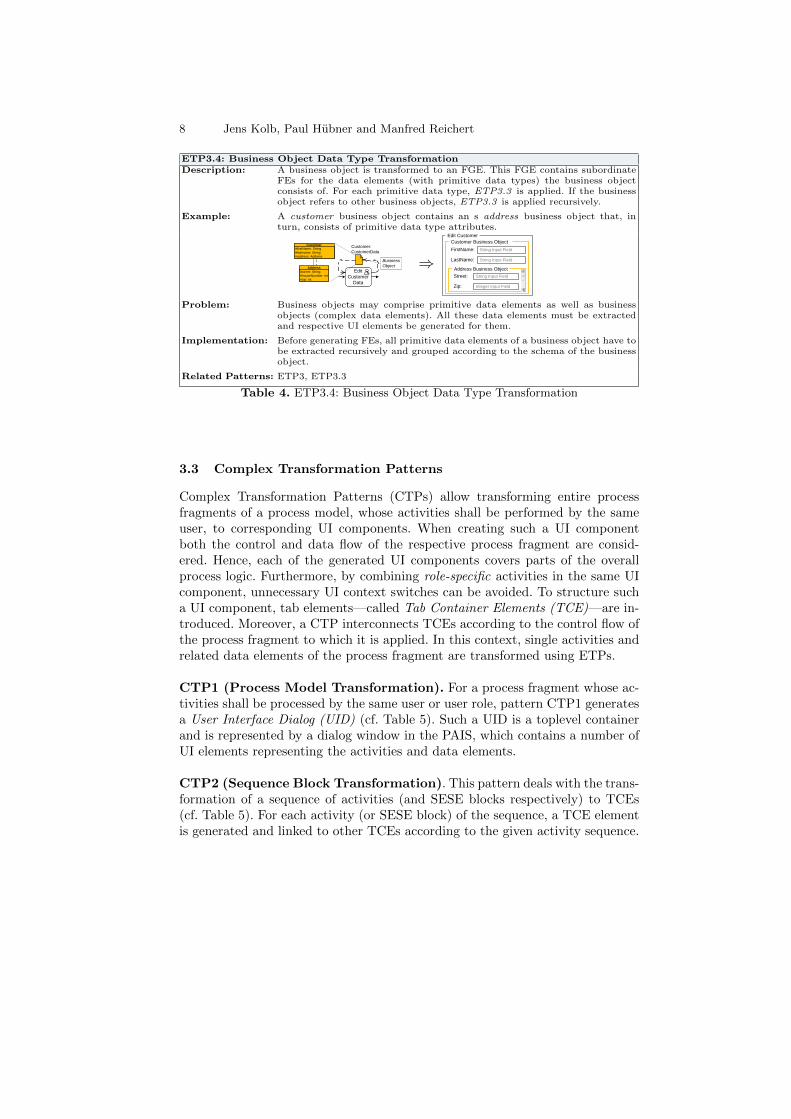
ETP3.4 (Business Object Data Type Transformation). To handle com-plex data types (i.e., business objects), pattern ETP3.4 can be applied (cf. Table4) [12]. It deals with data assembled of primitive or other complex data types. Forexample, a customer business object may consist of the primitive data elementsname, street, and birth date. The implementation of pattern ETP3.4 creates formgroup elements for logically grouping the primitive data elements the businessobject consists of.
8 Jens Kolb, Paul Hubner and Manfred Reichert
ETP3.4: Business Object Data Type TransformationDescription: A business object is transformed to an FGE. This FGE contains subordinate
FEs for the data elements (with primitive data types) the business objectconsists of. For each primitive data type, ETP3.3 is applied. If the businessobject refers to other business objects, ETP3.3 is applied recursively.
Example: A customer business object contains an s address business object that, inturn, consists of primitive data type attributes.
Edit
Customer
Data
Customer:
CustomerData
Customer#firstName: String
#lastname: String
#address: Address
Address
#street: String
#houseNumber: int
#zip: int
Business
Object
1
* ⇒
Edit Customer
Customer Business Object
String Input FieldFirstName:
String Input FieldLastName:
Address Business Object
String Input FieldStreet:
Integer Input FieldZip:
Problem: Business objects may comprise primitive data elements as well as businessobjects (complex data elements). All these data elements must be extractedand respective UI elements be generated for them.
Implementation: Before generating FEs, all primitive data elements of a business object have tobe extracted recursively and grouped according to the schema of the businessobject.
Related Patterns: ETP3, ETP3.3
Table 4. ETP3.4: Business Object Data Type Transformation
3.3 Complex Transformation Patterns
Complex Transformation Patterns (CTPs) allow transforming entire processfragments of a process model, whose activities shall be performed by the sameuser, to corresponding UI components. When creating such a UI componentboth the control and data flow of the respective process fragment are consid-ered. Hence, each of the generated UI components covers parts of the overallprocess logic. Furthermore, by combining role-specific activities in the same UIcomponent, unnecessary UI context switches can be avoided. To structure sucha UI component, tab elements—called Tab Container Elements (TCE)—are in-troduced. Moreover, a CTP interconnects TCEs according to the control flow ofthe process fragment to which it is applied. In this context, single activities andrelated data elements of the process fragment are transformed using ETPs.
CTP1 (Process Model Transformation). For a process fragment whose ac-tivities shall be processed by the same user or user role, pattern CTP1 generatesa User Interface Dialog (UID) (cf. Table 5). Such a UID is a toplevel containerand is represented by a dialog window in the PAIS, which contains a number ofUI elements representing the activities and data elements.
CTP2 (Sequence Block Transformation). This pattern deals with the trans-formation of a sequence of activities (and SESE blocks respectively) to TCEs(cf. Table 5). For each activity (or SESE block) of the sequence, a TCE elementis generated and linked to other TCEs according to the given activity sequence.

Automatic User Interface Generation 9
CTP1: Process Model TransformationDescription: For a particular process fragment, a surrounding User Interface Dialog (UID),
i.e., a toplevel container window, is generated. Following this, all other UIelements related to activities of this fragment are generated based on ETPsand CTPs, and are then embedded in the UID.
Example: All interactions with a clerk shall be done using the same UI component.
Process
FragmentSelect
Customer
Choose
Contact
Type
Edit
Address
Create
Customer
Send
Decision ⇒Account Creation: Clerk UI
UID
Problem: The UI elements related to the activities and data elements of a particularprocess fragment need to be mapped to a toplevel container window. TheUI flow logic (e.g., the ordering in which field elements may be displayed orwritten) corresponds to the control flow of the given process fragment.
Implementation: For each process fragment, a UID element (dialog window) is generated.
Related Patterns: None
CTP2: Sequence Block TransformationDescription: A sequence of activities (and SESE blocks respectively) is transformed into
a sequence of Tab Container Elements (TCE) to be processed in the samesequential order.
Example: A clerk first edits the customer data. Afterwards, he edits the correspondingcontact data.
Edit
Customer
Edit
Contact
Sequence Block
⇒Account Creation: Clerk UI
Edit Customer
Edit Contact
Edit Customer
TCE
Problem: Human activities, performed in sequence by the same user (role), shall be ac-complished using the same UI component, instead of using separate UI com-ponents (e.g., dialog windows) for each activity.
Implementation: For each activity (or SESE block), a TCE element is created. The order inwhich these TCEs may be processed, corresponds to the one of the respectiveactivities.
Related Patterns: ETP1, ETP2, ETP3, CTP3
Table 5. Pattern Descriptions for Patterns CTP1 and CTP2
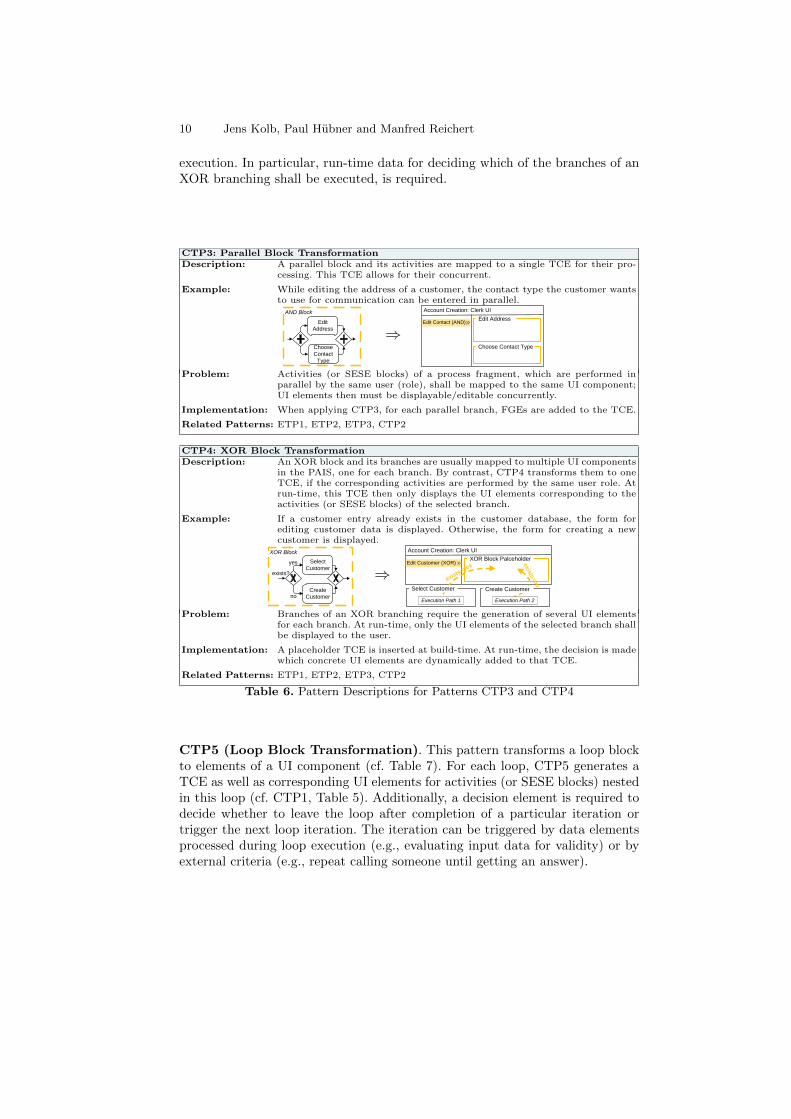
CTP3 (Parallel Block Transformation). This pattern transforms parallelactivities (or SESE blocks) of a process fragment to respective UI elements withinthe same UID. The UI elements may then be accessed concurrently (cf. Table 6).The resulting UI component is similar to the one of a single activity (cf. ETP1,Table 1). However, pattern CTP3 not only covers the transformation of activitiesor SESE blocks arranged in parallel. It also enables the concurrent processing ofarbitrary SESE blocks arranged in parallel to the respective UI elements.
CTP4 (XOR Block Transformation). This pattern is applied for trans-forming an XOR branching of a given process fragment to the UI component(cf. Table 6). CTP4 generates independent TCEs for each branch of the XORbranching. The decision, which branch and hence which TCE shall be selected,is made during run-time based on process data; e.g., whether the TCE elementfor creating a new customer or the one for editing an existing customer shall bedisplayed, depends on decision data that only becomes available during process
10 Jens Kolb, Paul Hubner and Manfred Reichert
execution. In particular, run-time data for deciding which of the branches of anXOR branching shall be executed, is required.
CTP3: Parallel Block TransformationDescription: A parallel block and its activities are mapped to a single TCE for their pro-
cessing. This TCE allows for their concurrent.
Example: While editing the address of a customer, the contact type the customer wantsto use for communication can be entered in parallel.
Choose
Contact
Type
Edit
Address
AND Block
⇒Account Creation: Clerk UI
Edit Contact (AND)
Choose Contact Type
Edit Address
Problem: Activities (or SESE blocks) of a process fragment, which are performed inparallel by the same user (role), shall be mapped to the same UI component;UI elements then must be displayable/editable concurrently.
Implementation: When applying CTP3, for each parallel branch, FGEs are added to the TCE.
Related Patterns: ETP1, ETP2, ETP3, CTP2
CTP4: XOR Block TransformationDescription: An XOR block and its branches are usually mapped to multiple UI components
in the PAIS, one for each branch. By contrast, CTP4 transforms them to oneTCE, if the corresponding activities are performed by the same user role. Atrun-time, this TCE then only displays the UI elements corresponding to theactivities (or SESE blocks) of the selected branch.
Example: If a customer entry already exists in the customer database, the form forediting customer data is displayed. Otherwise, the form for creating a newcustomer is displayed.
Select
Customer
Create
Customer
XOR Block
exists?
yes
no
⇒Account Creation: Clerk UI
XOR Block Palceholder
Select Customer
Execution Path 1
Create Customer
Execution Path 2
Edit Customer (XOR)
exists=yes
exis
ts=no
Problem: Branches of an XOR branching require the generation of several UI elementsfor each branch. At run-time, only the UI elements of the selected branch shallbe displayed to the user.
Implementation: A placeholder TCE is inserted at build-time. At run-time, the decision is madewhich concrete UI elements are dynamically added to that TCE.
Related Patterns: ETP1, ETP2, ETP3, CTP2
Table 6. Pattern Descriptions for Patterns CTP3 and CTP4
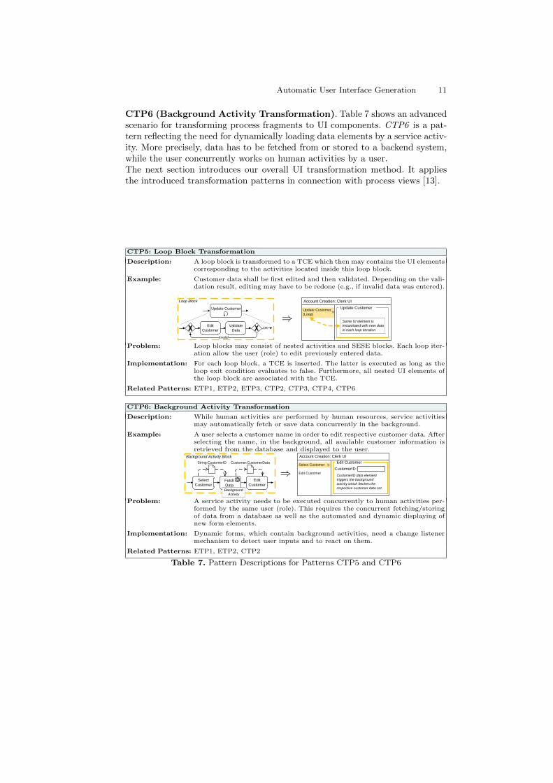
CTP5 (Loop Block Transformation). This pattern transforms a loop blockto elements of a UI component (cf. Table 7). For each loop, CTP5 generates aTCE as well as corresponding UI elements for activities (or SESE blocks) nestedin this loop (cf. CTP1, Table 5). Additionally, a decision element is required todecide whether to leave the loop after completion of a particular iteration ortrigger the next loop iteration. The iteration can be triggered by data elementsprocessed during loop execution (e.g., evaluating input data for validity) or byexternal criteria (e.g., repeat calling someone until getting an answer).
Automatic User Interface Generation 11
CTP6 (Background Activity Transformation). Table 7 shows an advancedscenario for transforming process fragments to UI components. CTP6 is a pat-tern reflecting the need for dynamically loading data elements by a service activ-ity. More precisely, data has to be fetched from or stored to a backend system,while the user concurrently works on human activities by a user.The next section introduces our overall UI transformation method. It appliesthe introduced transformation patterns in connection with process views [13].
CTP5: Loop Block Transformation
Description: A loop block is transformed to a TCE which then may contains the UI elementscorresponding to the activities located inside this loop block.
Example: Customer data shall be first edited and then validated. Depending on the vali-dation result, editing may have to be redone (e.g., if invalid data was entered).
Validate
DataOK
Invalid
Edit
Customer
Loop Block
Update Customer
⇒Account Creation: Clerk UI
Update Customer
(Loop)
Update Customer
Same UI element is
instantiated with new data
in each loop iteration
Problem: Loop blocks may consist of nested activities and SESE blocks. Each loop iter-ation allow the user (role) to edit previously entered data.
Implementation: For each loop block, a TCE is inserted. The latter is executed as long as theloop exit condition evaluates to false. Furthermore, all nested UI elements ofthe loop block are associated with the TCE.
Related Patterns: ETP1, ETP2, ETP3, CTP2, CTP3, CTP4, CTP6
CTP6: Background Activity Transformation
Description: While human activities are performed by human resources, service activitiesmay automatically fetch or save data concurrently in the background.
Example: A user selects a customer name in order to edit respective customer data. Afterselecting the name, in the background, all available customer information isretrieved from the database and displayed to the user.
Background Activity Block
Fetch
Data
Select
Customer
Edit
Customer
String:CustomerID Customer:CustomerData
Background
Activity
⇒Account Creation: Clerk UI
Select Customer
Edit Customer
Edit Customer
CustomerID:
CustomerID data element
triggers the background
activity which fetches the
respective customer data set
Problem: A service activity needs to be executed concurrently to human activities per-formed by the same user (role). This requires the concurrent fetching/storingof data from a database as well as the automated and dynamic displaying ofnew form elements.
Implementation: Dynamic forms, which contain background activities, need a change listenermechanism to detect user inputs and to react on them.
Related Patterns: ETP1, ETP2, CTP2
Table 7. Pattern Descriptions for Patterns CTP5 and CTP6
12 Jens Kolb, Paul Hubner and Manfred Reichert
4 Transforming Process Models to User Interfaces
Section 4 shows how the presented patterns can be used to transform processfragments into sophisticated UI components of the PAIS. In particular, we in-troduce a transformation method (cf. Section 4.1) and discuss how process frag-ments can be adapted through changes of the UI components (cf. Section 4.2).
4.1 User Interface Transformation Method
To transform a complete business process model, consisting of several processfragments, to multiple UI components, we introduced five steps (cf. Figure 3).Thereby, the number of generated UI components depends on the number ofdifferent users and user roles involved in the process.
Step 1. Role-specific process views [14,13,15] are created for the given processmodel. To be more precise, a process view abstracts from certain aspects of theprocess model. For example, it may only represent the activities of a particularuser role or organisational unit. In our context, a role-specific process view con-stitutes the basis for creating a role-specific UI component.
Step 2. For each process view, a User Interface Dialog (UID) is created. Asaforementioned, a UID acts as a toplevel container that includes all UI elementsrequired for processing the activities of a specific process view. For this purpose,pattern CTP1 is applied (cf. Table 5).
Step 3. In order to transform complete process fragments to UI elements, com-plex transformation patterns CTP2-6 are applied. For each CTP applied, a TabContainer Element (TCE) is generated. Each TCE is represented in the tab bararea (cf. Figure 3, Step 3). When clicking on an item in this area, the corre-sponding UI elements are displayed. If there are nested SESE blocks, they aredisplayed in a hierarchical tree in the tab bar area.
Step 4. Single activities (ETP1+2) are transformed into Form Group Elements(FGE). Basically, each FGE represents one activity in the process model. In caseof a parallel branching, multiple activities are displayed on a TCE element inthe UI (cf. Figure 3, Step 4).
Step 5. All data elements of the process view are transformed to Field Elements(FE). These are layouted and positioned within an FGE. In this context, thereexist different kinds of FEs depending on the data type of the respective dataelement (cf. ETP3.3, Table 3).
The structure of the resulting UI component is represented through a User Inter-face Model (UIM). Figure 4b shows an example of such a UIM. This tree-based

Automatic User Interface Generation 13
schema describes the hierarchical structure of the UI as generated by our trans-formation method. Section 4.2 shows that this UIM can be also used to propagatechanges of the UI component to the process model and vice versa.
4.2 Synchronizing Process Model and UI Changes
After generating complex UI components for a process model through processviews and deploying them in the PAIS, users may want to modify the UI. Forexample, they might add a new FE or re-position elements within the UI.
Select
Customer
Choose
Contact
Type
Edit
Address
Review
Account
Accept
Message
Decline
MessageCreate
Customer
Send
Decision
Process View
TCE
XOR
Edit
Customer
User Interface Dialog (UID)
Tab Container Element (TCE)Control Flow Block
Activity Form Group Element (FGE)
Data Element Field Element (FE)
CT
P A
pp
lic
ati
on
ET
P A
pp
lic
ati
on
Initial Process Model
Process Model User Interface
Account Creation: Clerk UI
Edit Customer (XOR)
Edit Contact (AND)
Send Decision
Choose Contact Type
Edit Address
Street
City
E-MailContact
Account Creation: Clerk UI
Edit Customer (XOR)
Edit Contact (AND)
Send Decision
Choose Contact Type
Edit Address
Account Creation: Clerk UI
Edit Customer (XOR)
Edit Contact (AND)
Send Decision
Account Creation: Clerk UI
Step 1: Role-Specific View Creation
Step 2: User Interface Creation
Step 3: Block Transformation
Step 4: Activity Transformation
Step 5: Data Transformation
TCE
SEQ
TCE
AND
Edit
Contact
FGE
Edit
Address
FGE
Choose
Contact
Type
FE
Contact
FE
City
FGE
Create
Customer
TCE
Send
Decision
...
FE
Street
UID
Create Account
FE
Address
...
User Interface Model
Clerk
Clerk
Clerk
Clerk
ClerkManager
Manager
Manager
User Roles
Select
Customer
Choose
Contact
Type
Edit
Address
Create
Customer
Send
Decision
Select
Customer
Choose
Contact
Type
Edit
Address
Create
Customer
Send
Decision
Select
Customer
Choose
Contact
Type
Edit
Address
Create
Customer
Send
Decision
FGE
Select
Customer
Select
Customer
Choose
Contact
Type
Edit
Address
Create
Customer
Send
Decision
ContactAddress
Fig. 3. Transformation Method
Basically, two categories of UI changes can be distinguished. Local changesare changes not affecting the associated process view. For example, assume thata user re-positions the FGE Edit Address within the TCE Edit Contact (AND)in Figure 4a. Such change would not affect the execution order of the activities
14 Jens Kolb, Paul Hubner and Manfred Reichert
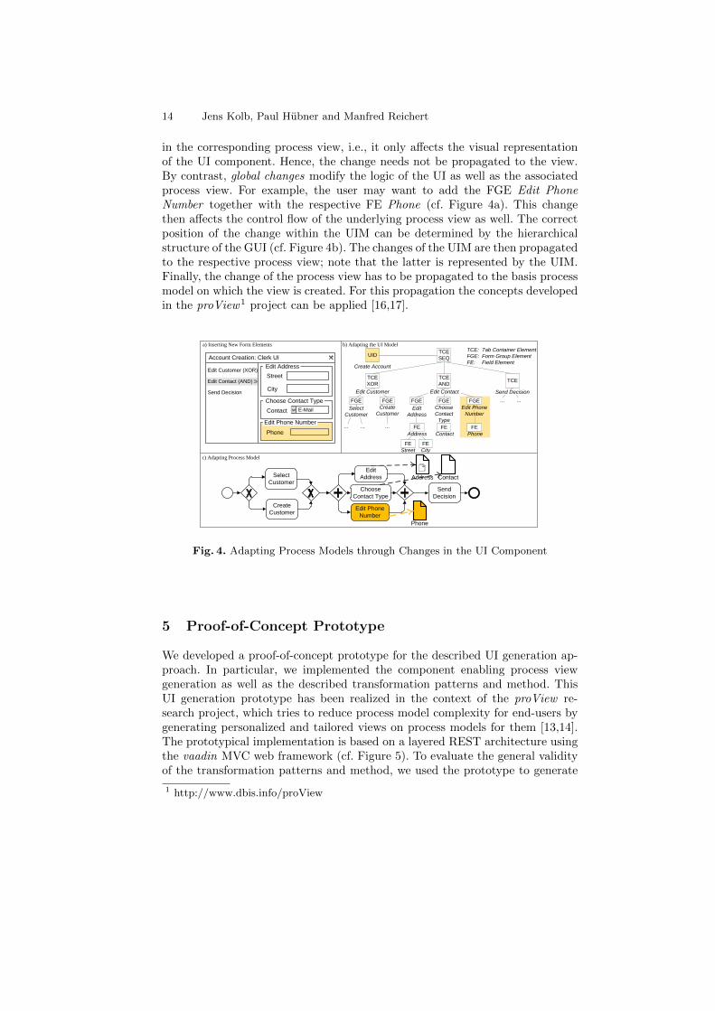
in the corresponding process view, i.e., it only affects the visual representationof the UI component. Hence, the change needs not be propagated to the view.By contrast, global changes modify the logic of the UI as well as the associatedprocess view. For example, the user may want to add the FGE Edit PhoneNumber together with the respective FE Phone (cf. Figure 4a). This changethen affects the control flow of the underlying process view as well. The correctposition of the change within the UIM can be determined by the hierarchicalstructure of the GUI (cf. Figure 4b). The changes of the UIM are then propagatedto the respective process view; note that the latter is represented by the UIM.Finally, the change of the process view has to be propagated to the basis processmodel on which the view is created. For this propagation the concepts developedin the proView1 project can be applied [16,17].
Account Creation: Clerk UI
Edit Customer (XOR)
Edit Contact (AND)
Send Decision
Edit Phone Number
Choose Contact Type
Edit Address
Street
City
E-MailContact
Phone
TCE
SEQ
TCE
XOR
Edit Customer
TCE
AND
Edit Contact
FGE
Choose
Contact
Type
FGE
Edit Phone
Number
FE
Contact
FE
City
FE
Phone
FGE
Select
Customer
FGE
Create
Customer
TCE
Send Decision
...... ...
... ...
TCE: Tab Container Element
FGE: Form Group Element
FE: Field Element
Edit Phone
Number
Select
CustomerChoose
Contact Type
Edit
Address
Create
Customer
Send
Decision
ContactAddress
Phone
a) Inserting New Form Elements b) Adapting the UI Model
FE
Street
c) Adapting Process Model
UID
Create Account
FE
Address
FGE
Edit
Address
Fig. 4. Adapting Process Models through Changes in the UI Component
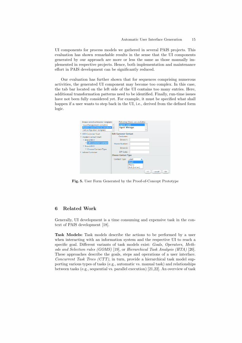
5 Proof-of-Concept Prototype
We developed a proof-of-concept prototype for the described UI generation ap-proach. In particular, we implemented the component enabling process viewgeneration as well as the described transformation patterns and method. ThisUI generation prototype has been realized in the context of the proView re-search project, which tries to reduce process model complexity for end-users bygenerating personalized and tailored views on process models for them [13,14].The prototypical implementation is based on a layered REST architecture usingthe vaadin MVC web framework (cf. Figure 5). To evaluate the general validityof the transformation patterns and method, we used the prototype to generate
1 http://www.dbis.info/proView
Automatic User Interface Generation 15
UI components for process models we gathered in several PAIS projects. Thisevaluation has shown remarkable results in the sense that the UI componentsgenerated by our approach are more or less the same as those manually im-plemented in respective projects. Hence, both implementation and maintenanceeffort in PAIS development can be significantly reduced.
Our evaluation has further shown that for sequences comprising numerousactivities, the generated UI component may become too complex. In this case,the tab bar located on the left side of the UI contains too many entries. Here,additional transformation patterns need to be identified. Finally, run-time issueshave not been fully considered yet. For example, it must be specified what shallhappen if a user wants to step back in the UI, i.e., derived from the defined formlogic.
Fig. 5. User Form Generated by the Proof-of-Concept Prototype
6 Related Work
Generally, UI development is a time consuming and expensive task in the con-text of PAIS development [18].
Task Models: Task models describe the actions to be performed by a userwhen interacting with an information system and the respective UI to reach aspecific goal. Different variants of task models exist: Goals, Operators, Meth-ods and Selection rules (GOMS) [19], or Hierarchical Task Analysis (HTA) [20].These approaches describe the goals, steps and operations of a user interface.Concurrent Task Trees (CTT), in turn, provide a hierarchical task model sup-porting various types of tasks (e.g., automatic vs. manual task) and relationshipsbetween tasks (e.g., sequential vs. parallel execution) [21,22]. An overview of task
16 Jens Kolb, Paul Hubner and Manfred Reichert
modeling approaches is provided in [23].
UI Description Language: As opposed to task models, UI description lan-guages describe the concrete elements a user interface consists of, instead of theirbehaviour. Nevertheless, some of these languages include basic task modelingconcepts as well [8]. Furthermore, respective languages are independent from aspecific programming language and enable software developers to describe a userinterface once, but deploy it on various devices (e.g., PC and tablets). Examplesof UI languages include: User Interface Markup Language (UIML) [24], AbstractUser Interface Markup Language (AUIML) [25], and User Interface ExtensibleMarkup Language (UsiXML) [26]. Based on these languages, UI descriptions canbe created at both built- and run-time.
Model-Driven UI Development: Model-driven UI development applies theprinciples of Model-Driven Development (MDD) to UI development. Althougha lot of competing approaches exist, an accepted standard for model-driven UIdevelopment is missing [8,27,28,29,30]. FlowiXML [8], for example, provides amethodology to develop UIs for business processes, taking the organizationalstructure as well as the process model into account. FlowiXML suggests aneight-step-approach based on various model types (e.g.: CTT, Petri Nets, andUsiXML). However, it does not allow for the automated generation of UIs. Basedon FlowiXML, [9] introduces the Business Alignment Framework. This four-step-approach provides task models (i.e., CTT) for user tasks with in the pro-cess model. Furthermore, a domain model supplements the task model. Basedon these models, an abstract UI description is generated and transformed intoa concrete UI component during process execution. This approach allows forchanges based on UIs and discuss how to manually align them with processmodels. However, automatic propagation is not supported.The approach provided in [31] transforms a process model into a human interac-tion perspective, which allows UI designers to specify data elements, user roles,tasks, and UI layout. This perspective enables detailed views on the processmodel. After manually refining them, corresponding UIs are generated duringrun-time. Furthermore, data-centered process management approaches offer adifferent (data-centered) view on business processes. Therefore, state transitionsof process-related data elements are described. Based on this information, UIscan be generated as well [10,32].
UI Generation in existing PAIS: Contemporary PAIS are able to createcertain UIs automatically (e.g., IBM WebSphere Lombardi [33]). To be moreprecise, single activities of a process model can be transformed into simple userforms, taking associated data elements into account similar to the ETPs. How-ever, more complex scenarios are not covered. None of the presented approachesallows for the automatic generation of complex user interfaces based on pro-cess models. Finally, the adaption of process models based on changes of thecorresponding UI is only considered rudimentarily.
Automatic User Interface Generation 17
7 Conclusion
In this paper, we showed how UI components can be automatically created fromentire process fragments and process models respectively. For this purpose, el-ementary and complex transformation patterns were identified and described.Furthermore, a transformation method, which applies these patterns to createcomplex UIs based on process views, were introduced. Our approach further en-ables the propagation of UI changes (e.g., adding new input fields) to the asso-ciated process model and vice versa. Finally, we implemented our UI generationapproach in a powerful proof-of-concept prototype. In summary, our approachwill contribute to reduce costs for PAIS development and maintenance.In future research, we will address the execution aspects of process models andassociated UIs as well. In this context, features such as jumping back to analready edited UI element will be supported by adapting the corresponding pro-cess instance to assure a valid history of its execution. Further, we started toimplement a UI editor which uses a set of predefined UI widgets and templatesfor creating sophisticated UI components for process models. In this editor, weuse our transformation method and change propagation features for derivingcomplete process models from the created complex UIs.
References
1. Pradeep, H.: Process-User Interface Alignment: New Value From a New Level ofAlignment. Align Journal (October 3, 2007)
2. Reichert, M., Weber, B.: Enabling Flexibility in Process-aware Information Sys-tems - Challenges, Methods, Technologies. Springer (2012)
3. Weber, B., Reichert, M., Mendling, J., Reijers, H.A.: Refactoring Large ProcessModel Repositories. Computers in Industry 62(5) (2011) 467–486
4. Reichert, M., Dadam, P.: ADEPTflex - Supporting Dynamic Changes of WorkflowsWithout Losing Control. Journal of Intelligent Inf. Sys. 10(2) (1998) 93–129
5. La Rosa, M., Wohed, P., Mendling, J., ter Hofstede, A.H.M., Reijers, H.A., van derAalst, W.M.P.: Managing Process Model Complexity Via Abstract Syntax Modi-fications. IEEE Transactions on Industrial Informatics 7(4) (2011) 614–629
6. Mendling, J., Strembeck, M.: Influence Factors of Understanding Business ProcessModels. In: Proc. BIS’08. (2008) 142–153
7. Dadam, P., Reichert, M.: The ADEPT Project: A Decade of Research and Devel-opment for Robust and Flexible Process Support. Computer Science - Researchand Development 23(2) (April 2009) 81–97
8. Garcia, J.G., Vanderdonckt, J., Calleros, J.M.G.: FlowiXML: A Step TowardsDesigning Workflow Management Systems. Int’l Journal of Web Engineering andTechnology 4(2) (2008) 163–182
9. Sousa, K., Mendonca, H., Vanderdonckt, J., Rogier, E., Vandermeulen, J.: UserInterface Derivation from Business Processes: A Model-Driven Approach for Or-ganizational Engineering. In: Proc. ACM SAC’08. (2008) 553–560
10. Kunzle, V., Reichert, M.: PHILharmonicFlows: Towards A Framework for Object-Aware Process Management. Journal Software Maintenance and Evolution: Re-search & Practice 23(4) (2011) 205–244

18 Jens Kolb, Paul Hubner and Manfred Reichert
11. Russell, N., ter Hofstede, A.H.M., Edmond, D., Aalst, W.M.P.V.D.: WorkflowData Patterns: Identification , Representation and Tool Support. In: Proc. ER2005. (2005) 353–368
12. Hongxin, A., Yusheng, X., Zhixin, M., Li, L.: Integrating User Interfaces by busi-ness Object States. In: Proc. ICISE’10. (2010) 2900–2903
13. Reichert, M., Kolb, J., Bobrik, R., Bauer, T.: Enabling Personalized Visualiza-tion of Large Business Processes through Parameterizable Views. In: Proc. ACMSAC’12, Riva del Garda (Trento), Italy (2012)
14. Kolb, J., Reichert, M.: Using Concurrent Task Trees for Stakeholder-centeredModeling and Visualization of Business Processes. In: Proc. S-BPM ONE 2012,CCIS 284. (2012) 237–251
15. Bobrik, R., Reichert, M., Bauer, T.: View-Based Process Visualization. In: Proc.5th Int’l Conf. on Business Process Management, Brisbane, Australia (2007) 88–95
16. Kolb, J., Kammerer, K., Reichert, M.: Updatable Process Views for User-centeredAdaption of Large Process Models. In: Proc. Intl. Conf. on Service Oriented Com-puting (ICSOC’12), Shanghai, China (2012) to appear
17. Kolb, J., Kammerer, K., Reichert, M.: Updatable Process Views for AdaptingLarge Process Models: The proView Demonstrator. In: Proc. of the BusinessProcess Management 2012 Demonstration Track, Tallinn, Estonia (2012) to appear
18. Hussmann, H., Meixner, G., Zuehlke, D.: Model-Driven Development of AdvancedUser Interfaces. Springer Berlin Heidelberg (2011)
19. Card, S., Moran, T., Newell, A.: The Psychology of Human-Computer Interaction.CRC (1983)
20. Annett, J.: Hierarchical Task Analysis. CRC (2003)21. Paterno, F., Mancini, C., Meniconi, S., Maria, V.S.: ConcurTaskTrees: A Diagram-
matic Notation for Specifying Task Models. In: Proc. IFIP TC13 Int’l Conf. onHuman-Computer Interaction. (1997) 362–369
22. Paterno, F.: ConcurTaskTrees : An Engineered Approach to Model-based Design ofInteractive Systems. The Handbook of Analysis for Human Computer Interaction(1999) 1–18
23. Limbourg, Q., Vanderdonckt, J.: Comparing Task Models for User Interface De-sign. The Handbook of Task Analysis for Human-Computer Interaction 6 (2004)
24. Abrams, M., Phanouriou, C., Batongbacal, A., Williams, S., Shuster, J.: UIML:An Appliance-Independent XML User Interface Language. Computer Networks31(11-16) (1999) 1695–1708
25. Azevedo, P., Merrick, R., Roberts, D.: OVID to AUIML-User-Oriented InterfaceModelling. In: Proc. 1st TUPIS’00. (2000)
26. Limbourg, Q., Vanderdonckt, J., Michotte, B., Bouillon, L.: USIXML: A LanguageSupporting Multi-path Development of User Interfaces. In: Engineering HumanComputer Interaction and Interactive Systems. (2005) 134–135
27. Puerta, A., Eriksson, H., Gennari, J.H., Musen, M.A.: Model-Based AutomatedGeneration of User Interfaces. In: Proc. 12th National Conference on ArtificialIntelligence. (1994) 471–477
28. Traetteberg, H., Molina, P.J.: Making Model-Based UI Design Practical: Usableand Open Methods and Tools. In: Proc. IUI’04. (2004) 376–377
29. Lu, X.: Model Driven Development of Complex User Interface. In: Proc. MoDELS2007, Workshop on Model Driven Development of Advanced User Interfaces. (2007)
30. Puerta, A., Maulsby, D.: MOBI-D: A Model-based Development Environment forUser-Centered Design. In: Proc. CHI’97. (1997) 4–5
31. Sukaviriya, N., Sinha, V.: User-Centered Design and Business Process Modeling:Cross Road in Rapid Prototyping Tools. In: Proc. INTERACT’07. (2007) 165–178

Automatic User Interface Generation 19
32. Kunzle, V., Reichert, M.: A Modeling Paradigm for Integrating Processes andData at the Micro Level. In: Proc. 12th Int’l Working Conference on BusinessProcess Modeling, Development and Support (BPMDS’11). (2011) 201–215
33. Yang, S., Sun, Y., Waterhouse, J., Lau, D., Al-Hamwy, T.: Modeling and Imple-menting a Business Process Using WebSphere Lombardi Edition 7.1. In: Proc.CASCON’10. (2010) 374–375