model: dl8 - xintop.com · model: dl8 dl8 specifications es-7691 rev.5 page 1/9 web data logger dl8...
TRANSCRIPT
MODEL: DL8
DL8 SPECIFICATIONS ES-7691 Rev.5 Page 1/9
Web Data Logger DL8
WEB-ENABLED REMOTE TERMINAL UNITFunctions and features• Remote monitoring of equipment and plants by usingmodern communication infrastructure• Monitoring and logging of a wide variety of signalsincluding temperature, pressure, voltage, discrete signalstatus• Flexible I/O types and scalable points by combining built-in R8 Series I/O modules• Type A has basic 'Browsing' function with web browser.• Type B is added with 'Reporting' function by e-mails.• Type C is added with 'Recording' function with SD card.• Type D is added with 'Advanced' functions of peer-to-peerconnection of I/O signals and customized web browser view.
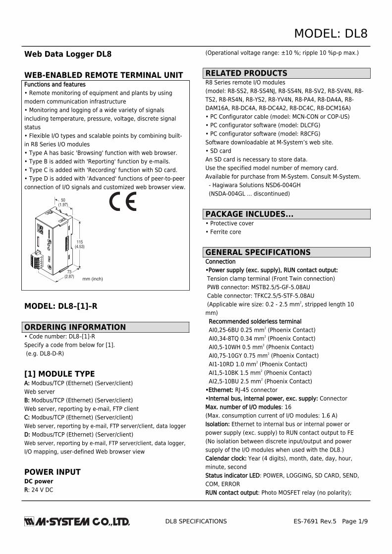
115(4.53)
mm (inch)
50(1.97)
73(2.87)
MODEL: DL8–[1]–R
ORDERING INFORMATION• Code number: DL8–[1]-RSpecify a code from below for [1]. (e.g. DL8-D-R)
[1] MODULE TYPEA: Modbus/TCP (Ethernet) (Server/client)Web serverB: Modbus/TCP (Ethernet) (Server/client)Web server, reporting by e-mail, FTP clientC: Modbus/TCP (Ethernet) (Server/client)Web server, reporting by e-mail, FTP server/client, data loggerD: Modbus/TCP (Ethernet) (Server/client)Web server, reporting by e-mail, FTP server/client, data logger,I/O mapping, user-defined Web browser view
POWER INPUTDC powerR: 24 V DC
(Operational voltage range: ±10 %; ripple 10 %p-p max.)
RELATED PRODUCTSR8 Series remote I/O modules(model: R8-SS2, R8-SS4NJ, R8-SS4N, R8-SV2, R8-SV4N, R8-TS2, R8-RS4N, R8-YS2, R8-YV4N, R8-PA4, R8-DA4A, R8-DAM16A, R8-DC4A, R8-DC4A2, R8-DC4C, R8-DCM16A)• PC Configurator cable (model: MCN-CON or COP-US)• PC configurator software (model: DLCFG)• PC configurator software (model: R8CFG)Software downloadable at M-System’s web site.• SD cardAn SD card is necessary to store data.Use the specified model number of memory card.Available for purchase from M-System. Consult M-System. - Hagiwara Solutions NSD6-004GH (NSDA-004GL ... discontinued)
PACKAGE INCLUDES...• Protective cover• Ferrite core
GENERAL SPECIFICATIONSConnection•Power supply (exc. supply), RUN contact output: Tension clamp terminal (Front Twin connection) PWB connector: MSTB2.5/5-GF-5.08AU Cable connector: TFKC2.5/5-STF-5.08AU (Applicable wire size: 0.2 - 2.5 mm2, stripped length 10mm) Recommended solderless terminal AI0,25-6BU 0.25 mm2 (Phoenix Contact) AI0,34-8TQ 0.34 mm2 (Phoenix Contact) AI0,5-10WH 0.5 mm2 (Phoenix Contact) AI0,75-10GY 0.75 mm2 (Phoenix Contact) AI1-10RD 1.0 mm2 (Phoenix Contact) AI1,5-10BK 1.5 mm2 (Phoenix Contact) AI2,5-10BU 2.5 mm2 (Phoenix Contact)•Ethernet: RJ-45 connector•Internal bus, internal power, exc. supply: ConnectorMax. number of I/O modules: 16(Max. consumption current of I/O modules: 1.6 A)Isolation: Ethernet to internal bus or internal power orpower supply (exc. supply) to RUN contact output to FE(No isolation between discrete input/output and powersupply of the I/O modules when used with the DL8.)Calendar clock: Year (4 digits), month, date, day, hour,minute, secondStatus indicator LED: POWER, LOGGING, SD CARD, SEND,COM, ERRORRUN contact output: Photo MOSFET relay (no polarity);
MODEL: DL8
DL8 SPECIFICATIONS ES-7691 Rev.5 Page 2/9
(OFF in error detected)•Peak load voltage: 50 V max.•Continuous load current: 50 mA max.•Peak load current: 300 mA max. (≤0.1 sec.)•Operation Power down: OFF Firmware operating: ON Error in EthernetLNK: OFF Internal bus controller error: OFF (Run contact output is applicable for Type C with the DL8firmware version 1.4.x or later.)
ETHERNET COMMUNICATIONCommunication Standard: IEEE 802.3uTransmission: 10BASE-T, 100BASE-TXBaud rate: 10/100 Mbps (Auto Negotiation function)Protocol: TCP/IP, Modbus/TCP, HTTP, FTP, SMTP, SNTPTransmission media: 10BASE-T (STP, Category 5), 100BASE-TX (STP, Category 5e)Max. length of fieldbus segment: 100 metersEthernet indicator LED: DPLX, LNKIP address: 192.168.0.1 (factory setting)
INSTALLATIONPower consumption•DC: Approx. 12 W 24 V DC (@ output current max. 1.6 A)Internal power•DC: 5 V DC•Operational current: 1.6 AExcitation supply output•DC: 24 V DC ±10 %•Operational current: 7 A (Power output current consumption must be under 7 A)Operating temperature: -10 to +55°C (14 to 131°F)Operating humidity: 30 to 90 %RH (non-condensing)Atmosphere: No corrosive gas or heavy dustMounting: DIN railWeight: 190 g (0.42 lb)
PERFORMANCEBattery: Vanadium-lithium secondary battery(undetachable)Calendar clock accuracy: Monthly deviation 2 minutes at25°CBattery backup: Approx. 2 monthsInsulation resistance: ≥ 100 MΩ with 500 V DCDielectric strength: 1500 V AC @ 1 minute (Ethernet tointernal bus or internal power or power supply (exc. supply)to RUN contact output to FE)
STANDARDS & APPROVALSEU conformity:EMC Directive EMI EN 61000-6-4 EMS EN 61000-6-2RoHS Directive EN 50581
MODEL: DL8
DL8 SPECIFICATIONS ES-7691 Rev.5 Page 3/9
COMPATIBLE BROWSING DEVICE■ Software requirementPC•OS: Windows Vista, Windows 7 (32bit/64bit), Windows 8.1 (32bit/64bit)•Browser: Internet Explorer 10, Internet Explorer 11 Firefox 13.0.1 or later Chrome 26.0.1410.43m or laterTablet•OS: iPad (iOS5 or later); Android terminal (Android4.0 or later)•Browser: iOS: Safari; Android: ChromeSmart phone•OS iPhone (iOS5 or later); Android terminal (Android4.0 or later)•Browser: iOS:Safari; Android: Chrome
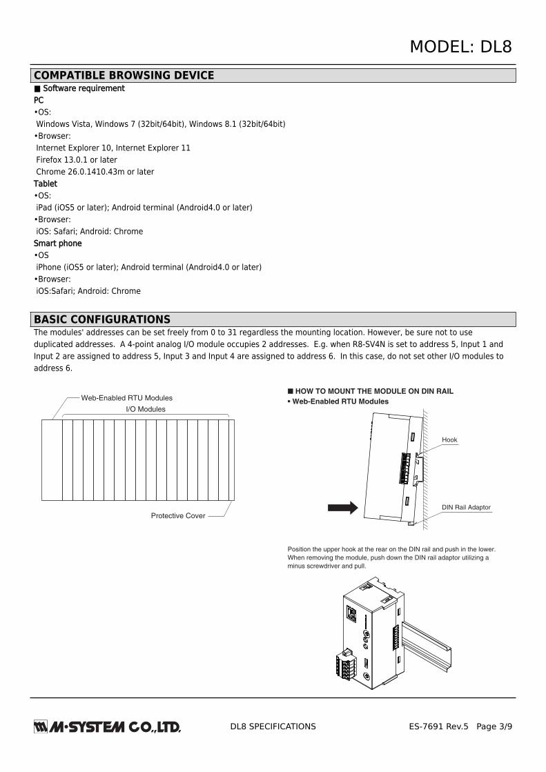
BASIC CONFIGURATIONSThe modules' addresses can be set freely from 0 to 31 regardless the mounting location. However, be sure not to useduplicated addresses. A 4-point analog I/O module occupies 2 addresses. E.g. when R8-SV4N is set to address 5, Input 1 andInput 2 are assigned to address 5, Input 3 and Input 4 are assigned to address 6. In this case, do not set other I/O modules toaddress 6.
I/O Modules
Web-Enabled RTU Modules
Protective Cover
Hook
DIN Rail Adaptor
■ HOW TO MOUNT THE MODULE ON DIN RAIL
• Web-Enabled RTU Modules
Position the upper hook at the rear on the DIN rail and push in the lower.
When removing the module, push down the DIN rail adaptor utilizing a
minus screwdriver and pull.

MODEL: DL8
DL8 SPECIFICATIONS ES-7691 Rev.5 Page 4/9
A
B
• I/O Module
Confirm that the locking clamps of the I/O module are set.
Insert the module in parallel to the next one while aligning the grooves of
both modules (A & B in the above figure).
Maintain it perpendicularly to the rail.
More I/O modules can be added in the same manner.

MODEL: DL8
DL8 SPECIFICATIONS ES-7691 Rev.5 Page 5/9
EXTERNAL VIEW
Status Indicator LED
Miniature Jack Connector for DLCFG
RJ-45 Connector for Ethernet
Logging Button (Type C & D)
SD Button (Type C & D)
SD Card Slot (Type C & D)
Miniature Jack Connector for R8CFG
Internal Bus Connector
DPLX
LNK
POWER
LOGGING
SD CARD
SEND
COM
ERROR
I/O
LOGGING
SD CARD
On
87
65
43
21
CFG
Function Setting DIP SW
87654321
On
Connector for Power Supply (Exc. supply),
RUN Contact Output
Ethernet Indicator LED
■ STATUS INDICATOR LED
LED Color Function
POWER Green
ON at device operating normally
Blinking at Ethernet LINK error
Blinking before obtaining DHCP address
LOGGING Green ON at logging (Type C & D)
SD CARD Green
ON during SD card mounted
Blinking at reading/writing SD card
(Type C & D)
SEND Green Blinking at e-mailing
COM GreenBlinking at communication
(except Modbus/TCP master)
ERROR Red ON at error
■ ETHERNET INDICATOR LED
LED Color Function
DPLX Amber ON at full duplex
LNK Green ON at link
CONNECTION DIAGRAMS■ POWER SUPPLY (EXC. SUPPLY), RUN CONTACT OUTPUT CONNECTOR TERMINAL ASSIGNMENT
Printed-circuit board connector (Phoenix Contact)
Header: MSTB2,5/5-GF-5,08AU
Plug component: TFKC2,5/5-STF-5,08AU
No. ID FUNCTION
1 24V Power supply (exc. supply) 24 V DC
2 0V Power supply (exc. supply) 0 V DC
3 RUN RUN contact output
4 RUN RUN contact output
5 FE Power supply (exc. supply) earth
12345
MODEL: DL8
DL8 SPECIFICATIONS ES-7691 Rev.5 Page 6/9
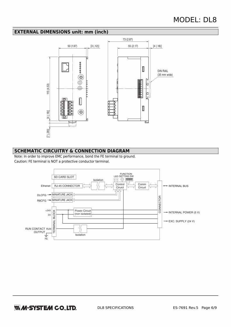
EXTERNAL DIMENSIONS unit: mm (inch)
50 (1.97) [3 (.12)]11
5 (4
.53)
[4 (
.18)
][7
(.2
8)]
55 (2.17)
73 (2.87)
DIN RAIL
(35 mm wide)
[4 (.18)]
SCHEMATIC CIRCUITRY & CONNECTION DIAGRAMNote: In order to improve EMC performance, bond the FE terminal to ground.Caution: FE terminal is NOT a protective conductor terminal.
CO
NN
EC
TO
R
INTERNAL POWER (5 V)
INTERNAL BUSCommCircuit
ControlCiruict
EXC. SUPPLY (24 V)
MINIATURE JACK
RJ-45 CONNECTOR
SD CARD SLOT
DLCFG
MINIATURE JACKR8CFG
Ethenet
LEDFUNCTION
SETTING SW
TE
RM
INA
L B
LO
CK+24V
0V
FE
Power Circuit(non isolated)
RUN CONTACT
OUTPUT
RUN
Isolation
Isolation

MODEL: DL8
DL8 SPECIFICATIONS ES-7691 Rev.5 Page 7/9
COMMUNICATIONIP:DHCP client is supported. Manual setting of IP address,subnet mask, default gateway and DNS server available too.Modbus/TCP slave:Remote observation system via SCADA etc.Modbus/TCP master:I/O expansion with remote I/O, e.g. R3 or R7 series, isavailable. Measuring points in multiple locations can behandled collectively.Web server function (Direct):This unit can be a Web server, and 'Data,' 'Trend' and 'EventLog' views are available from remote location.Web server function (Cloud):This unit can be an FTP client, and upload the Web files to acloud server.Users can browse the cloud server.Multiple users can access it at once without extra load atthe unit. (only browsing, operation not available.)Analog input: 32 pointsDiscrete input: 64 pointsPulse input: 32 pointsDiescrete output: 64 pointsAnalog output: 32 points (firmware version of the unit: 1.4.xor later)
ALARM OUTPUT (Type B, C & D)Event can trigger an alarm contact at a discrete outputmodule.•Transition of analog input zone•Transition of pulse input zone•Status change of discrete input•Count up of discrete input
EVENT REPORTING E-MAIL (Type B, C & D)Reporting e-mail function available at event or designatedtime.Encrypted communication is supported. (SMTP over SSL).The DL8 turns a designated Do ON after transmitting thereport.· Number of e-mail attention: 32· Number of event report text: 32· Number of regular report text: 1· Channel status: AI, DI, PI, DO, AO status attachable to e-mail(DO and AO are available with firmware version of the unit1.4.x or later)· Output at transmitting failure: 1 point
LOGGING (Type C & D)Log files in text format are stored into an SD card. Thenumber of logs depends on the free space of the SD card.Log file: System log, event log, e-mail report log, channellog
FTP CLIENT (Type B, C & D)The recorded data is uploaded to an FTP server in CSVformat in specified interval time.User can define the CSV file.•Number of channel: Max. 32 (Selectable within AI, DI, DI(counter), PI, DO, AO)(AO is selectable with firmware version of the unit 1.4.x orlater)•Sampling rate (Firmware version 1.6.x or later) 1 or 2 sec (Interval time: 1 or 10 min. or 1 hr.) 5, 10 or 30 sec. (Interval time: 10 min. or 1 hr.) 1, 2, 5, 10, 15, 20 or 30 min. (Interval time: 1 day)•Sampling rate (Firmware version 1.2.x or later) 1 or 2 sec (Interval time: 1 or 10 min. or 1 hr.) 5, 10 or 30 sec. (Interval time: 10 min. or 1 hr.) 1, 2, 5, 10 or 30 min. (Interval time: 1 day)•Sampling rate (Firmware version 1.1.x or earlier) 1, 2, 5, 10 or 30 sec. (Interval time: 1 hr.) 1, 2, 5, 10 or 30 min. (Interval time: 1 day)Note: To confirm the firmware version, use the configuratorsoftware, model: DLCFG.
TREND DATA STORING (Type C & D)The logged data is written into the SD card in CSV format.User can define the CSV file.•Number of channels: Max. 32 (Selectable within AI, DI, DI(counter), PI, DO, AO)(DO and AO are selectable with firmware version of the unit1.4.x or later)•AI sampling: Momentary, average, peak (max.), peak(min.)•Logging rate: Second: 1, 2, 5, 10, 20, 30 sec. Minute: 1, 2, 5, 10, 15, 20, 30 min. (15 min. is selectable with firmware version 1.5.x or later) On the hour: 0 to 23 o’clock (1 or more times available;specify time delay for each set time) Day start time and days to log are available.•Recordable up to the SD card size. Automatically deleted. (Auto delete is available with firmware version of the unit1.4.x or later)•Recording period (as a guide) Approx. 180 days (logging rate: 1 sec, 32 channels, only trend storing)
MODEL: DL8
DL8 SPECIFICATIONS ES-7691 Rev.5 Page 8/9
FTP SERVER (Type C & D)Reading and deleting files in the SD card by an FTP client isavailable.Compatible FTP client•Explorer•Web browser Internet Explorer version 10 and 11 Firefox version 13.0.1 or later
I/O MAPPING (Type D)Remote I/O connection is available by registering DI-to-DOor AI-to-AO mapping information.
USER DEFINED BROWSER VIEW (Type D)The browser view is user-definable.Development tools for HTML file are not available by M-System. Provide by customer.
OTHER FUNCTIONSConfiguration: Configurable with the dedicated softwaremodel: DLCFGTime zone: Selectable between –12:00 and +13:00(Time zone setting by minutes is not available for the DL8Ver.1.3 or earlier versions.)
MODEL: DL8
DL8 SPECIFICATIONS ES-7691 Rev.5 Page 9/9
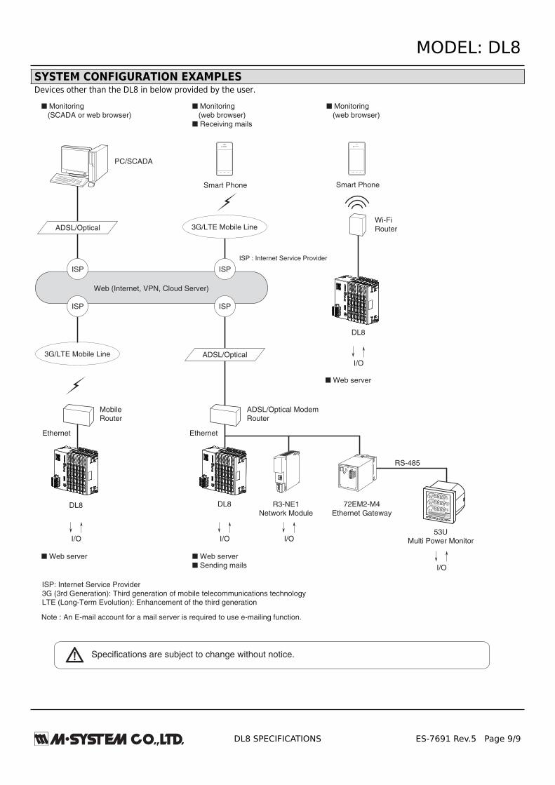
SYSTEM CONFIGURATION EXAMPLESDevices other than the DL8 in below provided by the user.
ISP : Internet Service Provider
■ Monitoring
(SCADA or web browser)
■ Monitoring
(web browser)
■ Receiving mails
■ Monitoring
(web browser)
■ Web server
Note : An E-mail account for a mail server is required to use e-mailing function.
PC/SCADA
3G/LTE Mobile Line
ADSL/Optical
Ethernet
MobileRouter
■ Web server
■ Sending mails
ADSL/Optical
Web (Internet, VPN, Cloud Server)
R3-NE1Network Module
Ethernet
RS-485
I/O I/O
I/O
ADSL/Optical ModemRouter
Wi-FiRouter
■ Web server
DL8
I/O
DL8
I/O
DL8
3G/LTE Mobile Line
Smart Phone Smart Phone
ISP
ISP
ISP
ISP
72EM2-M4
Ethernet Gateway
ETHERNET
RUNSENDFIELD
CNFG
RS-485
53UMulti Power Monitor
ISP: Internet Service Provider3G (3rd Generation): Third generation of mobile telecommunications technologyLTE (Long-Term Evolution): Enhancement of the third generation
AXIN
Specifications are subject to change without notice.