model based safety assessment (mbsa) in the space domain
TRANSCRIPT

HAL Id: hal-02064930https://hal.archives-ouvertes.fr/hal-02064930
Submitted on 12 Mar 2019
HAL is a multi-disciplinary open accessarchive for the deposit and dissemination of sci-entific research documents, whether they are pub-lished or not. The documents may come fromteaching and research institutions in France orabroad, or from public or private research centers.
L’archive ouverte pluridisciplinaire HAL, estdestinée au dépôt et à la diffusion de documentsscientifiques de niveau recherche, publiés ou non,émanant des établissements d’enseignement et derecherche français ou étrangers, des laboratoirespublics ou privés.
MODEL BASED SAFETY ASSESSMENT (MBSA) INTHE SPACE DOMAIN WITH CAPELLA
OPEN-SOURCE TOOLR. de Ferluc, F. Capogna, G. Garcia, O. Rigaud, D. Demarquilly, L. Bitetti
To cite this version:R. de Ferluc, F. Capogna, G. Garcia, O. Rigaud, D. Demarquilly, et al.. MODEL BASED SAFETYASSESSMENT (MBSA) IN THE SPACE DOMAIN WITH CAPELLA OPEN-SOURCE TOOL. Con-grès Lambda Mu 21, “ Maîtrise des risques et transformation numérique : opportunités et menaces ”,Oct 2018, Reims, France. �hal-02064930�
21e Congrès de Maîtrise des Risques et Sûreté de Fonctionnement λµ21 Reims 16-18 octobre 2018
MODEL BASED SAFETY ASSESSMENT (MBSA) DANS LE DOMAINE SPATIAL AVEC L’OUTIL OPEN-SOURCE CAPELLA
MODEL BASED SAFETY ASSESSMENT (MBSA) IN THE SPACE DOMAIN WITH CAPELLA OPEN-SOURCE TOOL
Bitetti L., Demarquilly D., Rigaud O., De Ferluc R., Garcia G. Capogna F. Thales Alenia Space European Space Agency 5 Allée des Gabians ESTEC Noordwijk, 2200 Cannes, 06150, France AG, The Netherlands
Résumé Ce papier présente les activités d’une étude en cours qui vise à challenger les redondances utilisées actuellement dans les satellites pour en optimiser la masse et le coût tout en gardant un niveau de fiabilité acceptable. Cela permettrait d’améliorer le design des futures missions spatiales et de déterminer quand et comment un changement entre une philosophie de tolérance aux pannes grâce à l’exploitation des redondances fonctionnelles plutôt que à des redondances à niveau équipement serait possible dans le domaine spatial. Une approche MBSA avec l’outil Capella et desalgorithmes d’optimisation masse-coût-fiabilité ont été développés pour supporter et améliorer les activités de co-ingénierie dès les phases amont du développement d’un satellite.
Summary This paper presents current activities aiming at deriving a generic approach for a satellite redundancy design alternative to the current full duplication of units. This approach will allow to improve the design of future missions and to derive when and how a change in the design philosophy from current fault tolerance thanks to the use of redundancies for each unit to a functional redundancy at satellite level could be possible in the space domain. A Model Based Safety Assessment approach with the Capella tool and a reliability-mass-cost optimization tool have been used to support these activities. These approaches and tools are expected to improve both the co-engineering activities and the product assurance process both required by the new space missions.
Introduction The in-orbit return over experience has shown that some satellite units have reliabilities higher than the computed ones and that several satellites remained in orbit for a period of time well beyond their expected lifetime. In addition they showed good performance and behavior even without ever using the redundant units. As a result, the redundant counterparts are often never used, which results in resources carried on-board that could have been retrospectively avoided. In addition, maintaining full functionality is not alwaysnecessary during all the mission phases and there have been some missions that have been partially or completely successful even after the occurrence of failures. Only some failures mainly related to already existing mechanical Single Point of Failure (SPF) have had major or critical consequences on the mission success. Finally, nowadays the usual strategy of adding redundancy to increase the reliability/availability of a satellite and its mission success is challenged by new missions, especially constellations, that have more and more stringent constraints in terms of mass budget, costs and time to market. Therefore a generic approach for a performance centered redundancy design alternative to the current full duplication avoiding non-operating redundancies is currently being investigated in the frame of an on-going project. This new approach will be used to identify, during the design phase of the satellite, the opportunities to remove full redundant systems when graceful degradation is possible and therefore to comply to restrictive requirements (e.g. mass, cost, complexity, reliability, safety, etc.). Note that graceful degradation is understood here as a degradation of performance that could be acceptable in case of failure in a no more fully redundant satellite but still guaranteeing the success of part of or ideally the totality of the mission.
This will allow to improve the design of future missions and to derive when and how a change in the design philosophy from current fault tolerance thanks to the use of redundancies for each satellite unit to a functional redundancy could be possible in the space domain.
Dependability process in the space domain The space domain is characterized by some specific needs and constraints which make the dependability process quite different compared to other engineering fields. Note that the rest of this paper is focused only on the satellite industry and not on launchers or crew missions. The satellite industry is characterized by:
• No or very limited series production (except for thenew mega-constellations) which makes eachsatellite quite unique and therefore requiring verylong development phases.
• No maintenance or repairing are possible operationsonce the satellite is in orbit (or at least with currenttechnologies even if on-orbit servicing mission arecurrently being studied).
• High reliability and availability are required and thisfor an extended period of time (e.g. 15 years ofcontinuous operation required for geostationarysatellites)
• Very aggressive external environment and operatingconditions (e.g. launch efforts, space radiations,extreme temperatures and thermal cycles, etc.).
• High autonomy of the satellite is required, especiallyin case of missions with limited ground visibility, andtherefore nominal and failure scenarios have to bemanaged by the satellite itself at the maximumextend.
In order to tackle all these needs and particularities, several activities are realized during a classical dependability process in the space domain :
Communication 2C /2 page 1/8

21e Congrès de Maîtrise des Risques et Sûreté de Fonctionnement λµ21 Reims 16-18 octobre 2018
• Feared Events Analysis (FEA) is performed atsatellite level at the beginning of the project, is afunctional top-down analysis. Its main objective is toidentify the feared events leading either to interruptthe mission or even to lose the spacecraft, and topropose recommendations to recover and ideallyavoid them.
• Failure Mode and Effect Analysis (FMEA) is abottom-up analysis which is started as soon as thephysical design of the satellite is known. The resultsof the FMEA are used as input to the design reviewsand for implementing corrective actions oroperational procedures to be followed in case offailures recovered by the ground.
• Fault Tree Analysis (FTA) is performed in order toensure that the design conforms to the failuretolerance requirement even in case of combinationsof failures. Note that this kind of analysis is rarelyrealized in the satellite industry, except for somespecific applications like those linked to safetyrequirements or the investigation of in-orbitanomalies.
• Failure Detection, Isolation and Recovery (FDIR)analysis. Fault management strategies andmechanisms are chosen in order to ensure thatavailability, autonomy and failure avoidance orrecovery requirements are fulfilled.
• Quantitative reliability analysis which are performedto demonstrate the compliance with the contractualrequirements. Starting from this high levelspecification, reliability figures are allocated to thedifferent systems and then specific redundancyschemes are chosen for each equipment in order toguarantee an overall good reliability and availabilityof the system. Reliability Block Diagrams (RBD) areusually used for this purpose.
While realizing the activities of this study it has been observed that there are some limits or at least some possible improvements in the dependability approach currently followed in the space domain. In fact it has been derived that :
• Graceful degradations are not, or not always, takeninto account during the requirements specificationand design phases. Redundancy schemes and faultmanagement strategies are therefore chosen inorder to guarantee a full success of the mission alsoin worst case scenario.This means that alternative and simplerarchitectures may probably exist in which somefailures could have a limited impact on the missionperformance and success even if the satellite is nolonger fully redundant and cross-strapped.
• The allocation at lower levels (subsystem andequipment) of the satellite reliability and availabilityrequirements is sometimes more linked to previouslyknown or expected designs rather than to a realneed at mission level. This can lead to a designwhere some functional chains may have a reliabilityhigher than the one really needed to guaranteeperformance and success of the mission.In addition, for some subsystems it may be more orless complex and costly to achieve a certainreliability figure. Therefore, the whole mass and costof the satellite could be optimized by taking intoaccount also this aspect during the allocation phase.
• Existing reliability tools are sometimes not designedor at least not optimized for the first phases of thesatellite development where multidisciplinaryactivities are realized iteratively in order to comparedifferent designs and to choose the best solution. Infact these tools are not always linked, or at least notdirectly, to the ones used by system engineers.
Therefore reliability aspects are taken into account only later, and sometime too late, or the coherence between these models is not always guaranteed, especially during these phases when the hypotheses and designs change very frequently.
• Fault management process usually starts late in thedevelopment process since not enough informationare available at the beginning. This could thereforelead to major design modifications and late changesthat are usually costly and with a great impact on theplanning.
• Finally main inputs for the dependability process atsystem level are the analyses realized at equipmentlevel and the documents describing the wholefunctions and architectures. However thesedocuments are not necessarily complete or not alldetailed diagrams are available. The missinginformation are therefore to be found in specificdocuments, if available at the time of the analysisare done, each describing the functions, thearchitecture or the interfaces of each unit. Thegathering of all the up-to-date information canbecome a time-consuming activity, especially incase of several re-issues of the documents or designmodifications. This is for instance the case of thefirst phases of the satellite development process orfor the classical intermediate reviews. Therefore thecoherence with the current design and thecorrectness of the dependability analyses could besometimes difficult to guarantee and especially toverify by a third party.
In order to address the future challenges in the space domain and to improve the co-engineering activities during the spacecraft design phase a MBSA approach based on the open source Capella tool and a mass-cost-reliability optimization tool have been considered as good potential candidates to solve some of these issues, or at least partially. The main goals and functionalities of these two tools are described in the rest of this paper.
MBSA approach with Capella tool The use of the Model Based System Engineering (MBSE) approach and in particular a Model Based Safety Assessment (MBSA) one has been envisaged in the frame of an on-going study. MBSE approaches have already been applied in different engineering domains and have demonstrated their interest and benefits. In fact, by enhancing the ability to capture, to analyze, to share and to manage the information associated with a whole product or system, MBSE approaches lead to :
• Improved communications among the developmentstakeholders (e.g. customer, managers, systemsengineers, hardware and software developers,testers, and specialty engineering disciplines).
• Increased ability to manage system complexity byenabling a system model to be viewed from multipleperspectives, and to analyze the impact of changes.
• Improved product quality by providing anunambiguous and precise model of the system thatcan be evaluated for consistency, correctness, andcompleteness.
• Enhanced knowledge capture and reuse of theinformation by capturing information in morestandardized ways and leveraging built inabstraction mechanisms inherent in model drivenapproaches.
The open source Capella tool [1], based on Arcadia method [2] has been used in the frame of an on-going project. Capella supports system engineering activities from requirements specification to the definition of the physical architecture, through the functional and logical analyses. In fact, different engineering steps and the
Communication 2C /2 page 2/8

21e Congrès de Maîtrise des Risques et Sûreté de Fonctionnement λµ21 Reims 16-18 octobre 2018
corresponding models and concepts are defined in Arcadia to cover all these aspects: Operational Analysis : focused on the analysis of the user needs and goals, the expected missions and the operational scenarios of the system. It allows to ensure the good adequacy of the system definition with regards to its real operational use; System Analysis : this level is used to model the system, viewed like a black box, by identifying its boundaries and external actors, and to clarify what the system is expected to do in the different phases of its whole mission to satisfy the former operational needs. At this stage the system actors, mission, capability and functions and the related functional exchanges are defined. Logical Analysis : used to develop the logical architecture of the system and to identify the components and their exchanges but excluding the physical implementation or technical issues. The system is seen here as a white box by defining how it will work as to fulfill expectations and by refining the previous system functions. In addition, the allocation of functions to components and the trade-offs between alternative architectures can be realized at this stage before defining a specific physical architecture in the next step. Physical Analysis : this final step of the Arcadia method aims at identifying the system physical components, their contents and relationships including the implementation or technical and technological aspects. It describes how the system will be developed and built, and makes the logical architecture evolve according to the final design.
For what concerns the MBSA approach with Capella, specific viewpoints or interfaces with external tool have already been developed or could be envisaged in order to support the main dependability activities realized in the space domain and presented before. To serve as an example, in [3] a link has been developed between Capella and the Safety Architect © tool [4]. This latter allows realizing risk analysis of complex systems using functional or physical architectures and provides support to the implementation of FMEA and automatically deducts the FTA corresponding to the identified feared events. However the existing Capella add-ons were not directly or not completely applicable to the on-going study mainly because of its specific goals but especially because of the particularities of the space domain compared to those for which the tools have been originally developed. In fact, as anticipated before, the Reliability Block Diagrams approach is preferred to the Fault Tree one in the satellite industry. This is why a new viewpoint specifically dedicated to the reliability allocation and assessment has been implemented in Capella. The rest of this section is mainly focused on this viewpoint whose main aim is to compute the reliability figures of a function or of the whole system starting from the Capella model realized by system engineers. The additional information that have to be filled by dependability engineers in the Capella model are the typical data needed to assess the reliability of a system (those highlighted in pink in the Figure 1) :
• The duty cycle (d.c.) : the ratio of functioning time over the total time for the identified element;
• The intrinsic failure rates of the units at full duty cycle (FIT ON), expressed in failure per 10^9 hours;
• The intrinsic failure rates of the units when not operating (FIT OFF). Note that multiplier factors of 1/10 and 1/100 are usually used for electrical and mechanical items, respectively;
• The quantity of units that are necessary to achieve a particular mission function (m);
• The quantity of units that are available (n) which should be higher or equal to m;
• The redundancy type : cold, hot, warm or no redundancy.
• Finally the user can also directly provide the reliability figure of one unit. This has been done especially for the mechanical items for which the reliability is assessed with the stress-strength method. In this case the probability is time independent and the failure rates are not defined.
Note that depending on the level of details and of the completeness of the system engineering models in Capella, it could be sometimes necessary to refine them because of the reliability assessment purpose. In fact, some information may be missing or, on the other hand, the models could be even simplified. Note that in the case of the Electrical Power Subsystem (EPS) of a generic satellite, shown hereafter as an example, there has been no need to further refine the Capella model since the same level of abstraction is found in the Reliability Bloc Diagrams (RBD) of the reliability model of this satellite subsystem. Figure 1 and Figure 2 show the reliability and the Capella models of this subsystem.
Figure 1. Reliability Block Diagram of the EPS subsystem
Figure 2. Capella Logical model of the EPS subsystem
It is recalled here that the three main functions of the EPS subsystem are to generate, store and deliver electrical power to all satellite units. The power is generated from the solar energy coming from the Sun thanks to the Solar Arrays (SA) whose orientation is changed by the Solar Array Drive Mechanism (SADM). The generated energy is then distributed to platform and payload users thanks to the Power Conditioning and Distribution Unit (PCDU). This equipment manages also the charge and discharge of the batteries which store the energy and represent an alternative source of power during the eclipse. In fact, in this portion of the orbit, the solar energy is not available and the electrical power needed to ensure the mission is provided by the battery. Finally the PCDU is also responsible of the communication with the on-board computer thanks to the TM/TC module. Once a Capella model is available, the previously mentioned reliability inputs have to be filled for all the
Communication 2C /2 page 3/8

21e Congrès de Maîtrise des Risques et Sûreté de Fonctionnement λµ21 Reims 16-18 octobre 2018
elements for which the reliability needs to be computed, as shown in Figure 3 for the EPS subsystem.
Figure 3. Capella model with reliability information
In addition the links between two Capella elements need to be defined in the reliability viewpoint. Some classical schemes can be selected :
• units in series, meaning for instance that the nominal and redundant modules of one equipment are linked only to the corresponding ones of another hardware;
• units fully cross-coupled, meaning that both the nominal and redundant modules of one equipment are linked to those of another hardware;
• units partially cross-coupled when not all the modules of one unit can be addressed by another unit
but the user has also the possibility to insert any desired mathematical formula that models any particular cross-strapping scheme between two units. To serve as an example, in the EPS subsystem presented before, the SA and the corresponding SADM are in series, whereas the PCDU TM/TC module and the on-board computer are cross-strapped. Once also this step is done, the Capella viewpoint provides as an output a table that gathers all the reliability parameters in a structured way and that can be then read and exploited by the already existing dependability tools based on Excel. To serve as an example, the output table for the previous example is shown in Figure 4.
Figure 4. Output of the Capella reliability viewpoint The reliability figures of a specific functional chain or of the whole system can therefore be computed with complex but well known mathematical formulae that are already implemented in the reliability software. Thanks to this reliability viewpoint, Capella could be used to easily and quickly compare different architectures proposed by system engineers during the early phases of the satellite development process and to choose the best one from the dependability and system engineering points of view. To serve as an example, Figure 5 shows four different solutions for the Telemetry, Tracking and Control (TT&C) subsystem of a generic satellite, and in particular for the ground telecommand reception. The main units in this
case are the TC omni antennas, the TC receivers and the TM/TC modules of the on-board computer. The first architecture corresponds to the one currently used in most of the satellites where all the units are cross-strapped, whereas in the last three configurations some or all of these cross-straps have been removed.
Figure 5. Capella viewpoint and reliability trade-offs
Thanks to the Capella viewpoint the reliability figures of these architectures have been computed and compared. It has been derived the second solution has a reliability similar to the one of the current architecture, whereas the last two lead to a much lower figures, which are well below the reliability value specified for this functional chain. Therefore, they have been considered as not acceptable from a dependability point of view. However, these two alternative solutions are very interesting from a system engineering point of view since the overall mass and costs of the subsystem can be significantly reduced, as shown in Figure 6 where the current solution is taken as the reference.
Figure 6. Multi-disciplinary trade-offs supported by Capella
Communication 2C /2 page 4/8
21e Congrès de Maîtrise des Risques et Sûreté de Fonctionnement λµ21 Reims 16-18 octobre 2018
It is therefore clear that all the different points of view need to be taken into account at the same time in order to choose a solution that could be interesting and accepted by all the stakeholders involved in the design of a satellite. In this sense, Capella could be used to support these multi-disciplinary trade-offs since:
• with the already existing Mass, Cost and Performance viewpoints [5] one can specify these values for each logical or physical component, and to compute the overall value for a specific functional chain up to the whole system,
•
• and with the Architecture Evaluation feature of Capella one can compare the quality of alternative architectures and verify that the client requirements are met thus facilitating system engineering decision-making since the early phases of the satellite design.
To conclude, Capella has been shown to be a promising tool for a MBSA approach supporting the dependability activities of the space domain. This MBSA approach is expected to improve the co-engineering activities between system engineers, equipment responsible and dependability experts, and to improve the product assurance process for the new space missions.
Reliability allocation and optimization tool At the same time, in order to more easily and quickly evaluate the feasibility and acceptability of these new architectures from a dependability point of view, some improvements have been identified also for the existing tools supporting reliability allocations and design choices. In this sense, an initial proof-of-concepts of a reliability-costs-mass optimization tool has been developed in addition to the MBSA approach with Capella that has been described before. It enables several applications that are of high interest during the early phases of the satellite development. To serve as an example, it allows to derive:
• How to achieve a given goal (e.g. the required satellite reliability) while optimizing the other parameters (e.g. limiting the whole mass and costs of the satellite)? This is the classical application in the space domain where redundancy schemes are selected in order to comply to both technical and product assurance requirements.
• How to reduce the cost or mass of the satellite while limiting the impact on the reliability? This could be for instance the case of an already existing platform whose design wants to be challenged in order to be optimized for a new mission, different from the one that has led to the current flight-proven design.
• How to achieve a given mass and/or cost objective while optimizing (maximizing) the whole spacecraft reliability? This corresponds for instance to the case of a constellation for which each satellite has very stringent requirements in terms of mass, costs and unit accommodation but for which the reliability and availability figures are less a concern. In fact, a lower satellite figure can be accepted since it can be compensated by the number of nominal and spare satellites available at constellation level.
Note that some examples of reliability allocation and optimization tools can be found in literature [6][7] but a different approach has been followed in the frame of the on-going study since these tools were not directly applicable or adapted to the aforementioned applications of the space domain. Two main reasons can be identified:
• First of all, the existing optimization tools allow deriving the best solution between a high number of possibilities thanks to genetic or nonlinear programming algorithms. However in our case there is only a limited number of options available for each
of the satellite subsystems. Other solutions could be interesting from a reliability point of view but it may be difficult to implement or accept them from other engineering points of view. To serve as an example, it could be difficult to have a given average temperature for one unit, or the number of units needed to achieve a given reliability could be not compatible with the satellite accommodation constraints or the required safety barriers.
• Secondly, the optimization algorithms usually require as an input the cost (and/or mass) evolution as a function of the component or system reliability. Most researchers adopt exponentially increasing function for the formulation of the optimal reliability allocation problem but from a satellite prime point of view it is easier to provide a cost (and/or mass) value for a specific architecture instead of deriving the precise mathematical expression of this curve.
Therefore, only the feasible solutions for the different satellite subsystems are taken as input of our optimization tool. For each of them, the corresponding mass, cost and reliability have to be computed before using the optimization algorithms. This approach has the minor drawback of requiring a pre-computation of these cost-mass-reliability discrete data sets. However this phase can be generalized at the maximum extend by considering that the possible design solutions are usually similar from a mission to another. In this way the optimization tool could be easily and quickly used also for different satellite missions. On the other hand, the main benefit of this approach is that once an optimal reliability allocation is found, one can directly derive what are the corresponding redundancy schemes required for the different satellite subsystems.
Note that in addition to the choice of particular redundancy schemes, other parameters contribute to the reliability result (e.g. the unit operating temperature, the quality of components, etc.) and therefore could be modified in order to optimize the overall system reliability. However that they are not taken into account in this first version of the optimization tool but they could be integrated in a future version. The main logic and steps beyond the optimization tool are briefly described hereafter and better presented with some figures in the rest of this section: 1. INPUTS
a. Retrieve the performance data (reliability, cost, mass) from the input table for each solution of the different satellite subsystems (see Figure 7)
b. Compute the delta of performance from one solution to another for each subsystem
c. Retrieve the user-selected initial solutions for each satellite subsystem (see Figure 9 and Figure 11)
d. Compute the initial system performance: reliability, cost, mass (see Figure 9 and Figure 11)
e. Retrieve the performance objective and the optimization type (see Figure 9 and Figure 11)
2. ITERATIONS: Do
a. Loop on all the satellite subsystems i. Evaluation of delta performance while moving to the
following solution ii. Evaluation of delta performance over delta optimization
parameter iii. Keep the subsystem solution leading to the best ratio
b. Update the previous subsystem solutions with the new one
While Performance objective is not reached
3. OUTPUTS (see Figure 10 and Figure 12) :
a. Final and optimized solutions for each subsystem b. Final and optimized system performance c. Table and plots showing the evolution of performance and
subsystems solutions at each iteration
Communication 2C /2 page 5/8

21e Congrès de Maîtrise des Risques et Sûreté de Fonctionnement λµ21 Reims 16-18 octobre 2018
Figure 7 shows the value that have been used to validate this proof-of-concept of the optimization tool. Note that even if they do not necessarily coincide with the real values of the main satellite subsystems, they allow anyway to demonstrate the validity and interest of such an optimization approach.
Figure 7. Cost-mass-reliability inputs data sets
By analyzing Figure 8, that shows the evolution of the costs as a function of the reliability, one can derive that the change from a solution to another (which corresponds to a specific change in the reliability) may lead to a limited or huge impact on the overall costs depending on the considered subsystem and initial solution.
Figure 8. Reliability-Cost penalty function
In fact, the increase of the reliability of a low reliability configuration requires “only” a limited Cost, while the improvement for an already reliable architecture leads to important extra costs. It is therefore clear that one will intuitively chose those design changes with the highest ratio Reliability over Cost among those subsystems that have the highest contribution to the satellite unreliability. This is the main logic beyond each step of the optimization process which reflects the approach that is already followed by system and dependability engineers during the satellite development process. The main advantage here is that, in addition of supporting the realization of these multidisciplinary activities with the same and shared tool, this optimization tool allows to take into account all the functional chains or subsystems at the same time. Having a global approach is very important since, as derived from the return of experience of previous missions, in some cases the optimizations have been realized for each subsystem at a time and some potential solutions have been discarded because of a too high impact on the satellite reliability or performance. However, these alternative solutions could have been probably accepted by considering that their drawbacks may have been
compensated by the benefits of another solution with an overall gain in terms of mass, costs and reliability. In the rest of this section the result of two applications of the optimization tool are shown. In the first case the goal is to derive the satellite configuration allowing to achieve a given (better) reliability while limiting the cost, the mass or both at the same time, starting from the simplest and cheapest architecture. In fact, the first solution of each subsystem is selected in this case, as shown in Figure 9, which leads to an overall reliability, cost and mass values of 0.321, 860 k€ and 95 kg respectively. The reliability goal has been arbitrarily chosen equal to 0.6 ± 0.01. Note that a cost optimization has been chosen here.
Figure 9. Optimization parameters for Case 1
Figure 10 shows what are the solutions chosen for each subsystem at each iteration realized by the optimization tool and the corresponding overall reliability, cost and mass of the system.
Figure 10. Iterations and optimization results for Case 1
One can derive that the reliability goal is reached (0.605 versus the 0.6 required) in only few iterations. With the optimum solutions found here for each subsystem, the overall cost and mass of the system are respectively of 2250 k€ and 210 kg. Note that, even if the detailed results
1 2 3 4 5 6 7EPS 1 1 1 1 1 2 2 2DHS 1 2 3 3 3 3 3 3
AOCS 1 1 1 2 2 2 2 2XPS 1 1 1 1 1 1 2 3
TT&C 1 1 1 2 3 4 4 4reliability 0,321 0,343 0,364 0,407 0,430 0,471 0,538 0,605
cost 860 900 950 1050 1100 1250 1750 2250mass 95 125 155 162 165 200 205 210
Iteration number
Communication 2C /2 page 6/8
21e Congrès de Maîtrise des Risques et Sûreté de Fonctionnement λµ21 Reims 16-18 octobre 2018
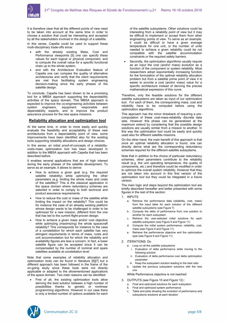
are not shown here, by choosing to optimize the mass instead of the cost, a different combination of subsystems’ architectures is found and the overall cost and mass are in this case equal to 3960 k€ and 185 kg. A solution leading to a lower mass is found here but, as expected, it is associated to a higher cost. Finally note that for some missions it could be interesting to optimize the two parameters at the same time. In this case the user has also the possibility to choose any desired factor in order to define the relative weight of the two parameters. In the second case the goal is to derive the satellite configuration allowing to achieve a given (lower) reliability while reducing at the maximum extend the cost, the mass or both. The initial solution here is the most complex and costly architecture since the last solution of each subsystem is selected in this case. As shown in Figure 11, this leads to an overall reliability, cost and mass values of 0.821, 5335 k€ and 429 kg respectively. The reliability goal has been chosen once again equal to 0.6 ± 0.01 in order to derive if the optimization tool provides the same solution of the previous case or not.
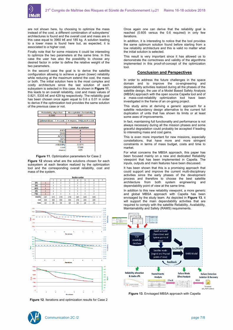
Figure 11. Optimization parameters for Case 2 Figure 12 shows what are the solutions chosen for each subsystem at each iteration realized by the optimization tool and the corresponding overall reliability, cost and mass of the system.
Figure 12. Iterations and optimization results for Case 2
Once again one can derive that the reliability goal is reached (0.605 versus the 0.6 required) in only few iterations. In addition, it is interesting to notice that the tool provides the same optimum solution found before starting from a low reliability architecture and this is valid no matter what the initial solution is selected. This result is very important since it has allowed us to demonstrate the correctness and validity of the algorithms implemented in this proof-of-concept of the optimization tool.
Conclusion and Perspectives
In order to address the future challenges in the space domain and to improve the co-engineering and dependability activities realized during all the phases of the satellite design, the use of a Model Based Safety Analysis (MBSA) approach with the open source Capella tool and of a mass-cost-reliability optimization tool have been investigated in the frame of an on-going project. This study aims at deriving a generic approach for a satellite redundancy design alternative to the current full duplication of units that has shown its limits or at least some axes of improvements. In fact, maintaining full functionality and performance is not always necessary during all the mission phases and some graceful degradation could probably be accepted if leading to interesting mass and cost gains. This is even more important for new missions, especially constellations, that have more and more stringent constraints in terms of mass budget, costs and time to market. For what concerns the MBSA approach, this paper has been focused mainly on a new and dedicated Reliability viewpoint that has been implemented in Capella. The inputs, outputs and main features have been discussed. It has been shown that this is a promising approach that could support and improve the current multi-disciplinary activities since the early phases of the development process and therefore to choose the best satellite architecture from both system engineering and dependability point of view at the same time. In addition to this new reliability viewpoint, a more generic and global MBSA approach with Capella has been envisaged by the study team. As depicted in Figure 13, it will support the main dependability activities that are required to comply with the satellite Reliability, Availability, Maintainability and Safety (RAMS) requirements.
Figure 13. Envisaged MBSA approach with Capella
1 2 3 4 5 6 7EPS 4 4 4 3 2 2 2DHS 4 4 4 4 4 3 3
AOCS 4 3 3 3 3 3 2XPS 4 4 3 3 3 3 3
TT&C 4 4 4 4 4 4 4reliability 0,821 0,813 0,739 0,700 0,661 0,625 0,605
cost 5300 5000 3500 3000 2700 2400 2250mass 425 365 350 320 300 240 210
Iteration number
Communication 2C /2 page 7/8

21e Congrès de Maîtrise des Risques et Sûreté de Fonctionnement λµ21 Reims 16-18 octobre 2018
Taking as inputs the failure time, feared events or failure modes of each component, a specific and dedicated viewpoint can be used to capture this information and to realize or at least initialize the main dependability analyses and artifacts. This MBSA approach is expected to improve the co-engineering activities between system engineers, equipment responsible and dependability experts, and to improve the current product assurance process which is indispensable for new space missions, especially for mega-constellations based on ‘low cost’ satellites.
In addition, an initial proof-of-concepts of a reliability-mass-cost optimization tool has been developed in order to more easily and quickly evaluate the feasibility and acceptability of new and disruptive solutions currently being evaluated in order to comply with stringent mass and cost requirements. This tool is thought to be very promising since it could support the co-engineering activities and enabling several applications that are of high interest during the early phases of the satellite development. Note that in addition to the applications already discussed in this paper :
• to achieve a given goal (e.g. the required satellite reliability) while optimizing the other parameters (e.g. limiting the whole mass and/or costs of the satellite).
• to reduce the cost and/or the mass of the satellite while limiting the impact on the reliability.
• to achieve a given mass and/or cost objective while optimizing (maximizing) the whole spacecraft reliability.
other possible applications of this tool have been anticipated and will have to be further evaluated in future dedicated studies:
• to evaluate the impact of a lower/higher reliability requirement specified by the customer in terms of delta cost or delta mass and therefore to propose and justify a lower requirement, for instance, during co-engineering activities;
• to allocate reliability requirements per subsystem taking into account its feasibility and impact on costs and mass;
• to take into account also the severity of the alternative redundancy architectures and their impact not only on the satellite reliability but also on the mission availability.
The correctness and validity of the algorithms of the optimization tool have already been demonstrated with arbitrarily chosen data sets but the next step will consist in evaluating and validating its results with real cost and mass. For this purpose, the optimization tools could be linked to the MBSA approach presented before : its input values could be directly derived from the multidisciplinary trade-offs of alternative solutions supported by the Capella system engineering and dependability viewpoints.
To conclude, the MBSA approach with the Capella open-source tool and the optimization tool investigated in the frame of the on-going study are expected to improve the design of future missions and to derive when and how a change in the design philosophy from current fault tolerance to fault acceptance could be possible in the space domain.
Reference
[1] CAPELLA : Model Based System Engineering (MBSE) tool: https://www.polarsys.org/capella/ index.html
[2] ARCADIA : Model Based System Engineering (MBSE) method: https://www.polarsys.org/capella/ arcadia.html
[3] Clarity project : http://www.clarity-se.org/ [4] Safety Architect © : www.all4tec.net/safety-architect [5] Capella Mass/Cost/Performance Viewpoints :
https://wiki.polarsys.org/Capella/Viewpoints/BasicView points
[6] Adamantios Mettas, ReliaSoft Corporation, “Reliability Allocation and Optimization for Complex Systems”.
[7] J. Faure, R. Laulheret, A. Cabarbaye, “Is Optimized Deign of Satellites Possible ?”, ESRL 2008 conference
Communication 2C /2 page 8/8