model-based quantity takeoff in...
TRANSCRIPT

Model-based Quantity Takeoff in Production
An experimental and interview-based approach on site to develop and implement new work methods
Master of Science Thesis in the Master’s Programme Design and Construction
Project Management
ADAM LINDSTRÖM Department of Civil and Environmental Engineering Division of Construction Management
CHALMERS UNIVERSITY OF TECHNOLOGY Göteborg, Sweden 2013 Master’s Thesis 2013:22


MASTER’S THESIS 2013:22
Model-based Quantity Takeoff in Production
An experimental and interview-based approach on site to develop and implement new work methods
Master of Science Thesis in the Master’s Programme Design and Construction
Project Management
ADAM LINDSTRÖM
Department of Civil and Environmental Engineering Division of Construction Management
CHALMERS UNIVERSITY OF TECHNOLOGY
Göteborg, Sweden 2013

Model-based Quantity Takeoff in Production
An experimental and interview-based approach on site to develop and implement new work methods
Master of Science Thesis in the Master’s Programme Design and Construction
Project Management
ADAM LINDSTRÖM
© ADAM LINDSTRÖM, 2013
Examensarbete / Institutionen för bygg- och miljöteknik, Chalmers tekniska högskola 2013:22
Department of Civil and Environmental Engineering
Division of Construction Management
Chalmers University of Technology
SE-412 96 Göteborg
Sweden Telephone: + 46 (0)31-772 1000
Cover: A viewpoint of building elements and spaces from the reference project´s building information model.
Chalmers Reproservice / Department of Civil and Environmental Engineering Göteborg, Sweden 2013


I
Model-based Quantity Takeoff in Production An experimental and interview-based approach on site to develop and implement new
work methods
Master of Science Thesis in the Master’s Programme Design and Construction
Project Management
ADAM LINDSTRÖM Department of Civil and Environmental Engineering Division of Construction Management Chalmers University of Technology
Effective information sharing between different parties involved in a project is important and BIM, Building Information Modelling, is often used in design but rarely in production. One aspect of BIM technology is easier quantity takeoff but lack of BIM competence, high initial costs, different procurement systems, and low interoperability between software have proven to be great barriers for the implementation of BIM technology in projects. The purpose of this master thesis is to investigate how model-based quantity takeoff should be implemented in production. Five weeks of field observations have been conducted on a reference project and production managers, BIM consultants, and other practitioners of interest have been interviewed. By trying alternative work methods doing quantity takeoffs from the reference project´s BIM current ways of quantifying have been iteratively improved. Primarily, this master thesis aims at production quantities in facilities and residential projects and focus has been on quantities needed for a general contractor and works related to core complements. Sweden has a lot to learn about BIM from our Scandinavian neighbours and this study shows that if all information in a project is organised in a rational and consistent way there is a lot to gain. In Sweden, quantifying of material in production is in many projects done by using scale bar and coloured pens. Model-based quantity takeoff saves time, reduces waste, and gives opportunity to control invoices more frequently. However, implementation of model-based quantity takeoff in production must be done in several steps, the first step being to get production personnel working digitally with drawings using PDF viewers. The second step is to achieve consistency in nomenclature and no more information than a correct littera is necessary in the model at this stage. Additional information may later on be connected to the model by XML documents enabling other parties than designers to add information as a project develops. Quantifying material is an important task of learning a project and keeping a high level of visualisation is important in order to control both input and output of the quantity takeoff. A plan view on the bottom and colour-coding of object types help production managers to visually control the quantity takeoff. Information in current room description documents may be connected to spaces in the project´s BIM which make construction parts as skirting boards and bath room mirrors easy to quantify. Moreover, to be successful new ways of working should be pulled into production by production personnel that wish to use them, not pushed out to production by support functions.
Key words: BIM, information management, quantity takeoff, quantify, production

II
Modellbaserad mängdavtagning i produktion
En experimentell och intervjubaserad metod på arbetsplatsen för att utveckla och
implementera nya arbetssätt
Examensarbete inom Design and Construction Project Management
ADAM LINDSTRÖM
Institutionen för bygg- och miljöteknik
Avdelningen för Construction Management
Chalmers tekniska högskola
SAMMANFATTNING
Effektivare informationsutbyte mellan olika parter involverade i ett projekt är viktigt och BIM, byggnadsinformationsmodellering, används ofta i projektering men sällan i produktion. En möjlighet med BIM är enklare mängdavtagning men bristen på BIM-kompetens, höga initiala kostnader, olika upphandlingssystem och låg interoperabilitet mellan olika programvaror har visat sig vara stora hinder för implementeringen av BIM i projekt. Syftet med detta examensarbete är att undersöka hur modellbaserad mängdavtagning bör implementeras i produktion. Fältobservationer har under fem veckor gjorts på ett referensprojekt och produktionsledare, BIM-konsulter och andra aktörer av intresse har intervjuats. Genom att pröva alternativa arbetsmetoder för mängdavtagning med referensprojektets BIM har nuvarande arbetssättsätt för mängdavtagning iterativt förbättrats. Detta examensarbete syftar främst på produktionsmängder i hus- och bostadsprojekt och fokus har legat på mängder gällande stomkomplettering som behövs för en huvudentreprenör. Sverige har mycket att lära om BIM från våra nordiska grannländer och denna studie visar att om all information i ett projekt organiseras på ett rationellt och konsekvent sätt finns det mycket att vinna. I Sverige används skalstock och färgpennor i många projekt för att ta fram produktionsmängder och modellbaserad mängdavtagning sparar tid, minskar svinn och ger möjlighet att kontrollera fakturor oftare. Implementeringen av modellbaserad mängdavtagning i produktion måste ske i flera steg, det första steget är att få produktionspersonal att arbeta digitalt med ritningar med hjälp av PDF-hanterare. Det andra steget är att uppnå en konsekvent nomenklatur och ingen mer information i modellen än ett korrekt littera är nödvändigt i detta skede. Ytterligare information kan senare anslutas till modellen genom XML-dokument vilket möjliggör andra parter än projektörer att lägga till information allt eftersom projektet utvecklas. Att mängda material är en viktig uppgift för att lära sig ett projekt och det är även viktigt att hålla en hög grad av visualisering för att kunna kontrollera både indata och utdata av mängdavtagningen. Genom att lägga en planritning på botten och färgkoda alla objekttyper kan produktionsledare visuellt kontrollera mängdavtagningen. Informationen i nuvarande rumsbeskrivningar kan anslutas till rumsvolymer i projektets BIM vilket gör att byggnadsdelar såsom golvlister och badrumsspeglar är lätta att mängda. Nya arbetssätt måste dessutom dras in i produktionen av produktionspersonalen som önskar använda dem, inte tryckas ut i produktionen av stödfunktioner.
Nyckelord: BIM, byggnadsinformationsmodellering, byggnadsinformationsmodeller, mängdavtagning, mängdning, produktion

CHALMERS Civil and Environmental Engineering, Master’s Thesis 2013:22 III
Contents
SAMMANFATTNING II
CONTENTS III
PREFACE VI
ABBREVIATIONS VII
1 INTRODUCTION 1
1.1 Background 1
1.2 Purpose and Problem Definition 1
1.3 Research Questions 2
2 THEORETICAL BACKGROUND 3
2.1 2D CAD 3
2.2 Bills of Quantities 3
2.3 Explaining the acronym BIM 3
2.4 The use of BIM 5
2.4.1 3D Visualisation 5
2.4.2 Clash Detection 6
2.4.3 4D BIM, 3D + time 7
2.4.4 5D BIM, 3D + time + cost 8
2.5 Interoperability between Different Software 8
2.6 Usage of BIM in Other Nordic Countries 9
2.6.1 A Brief Summary of Quantity Takeoff Guidelines in Finland 9
2.7 Two ways of using a BIM to estimate costs 9
3 METHOD 11
3.1 Methodology 11
3.2 Company Presentation of Skanska 12
3.2.1 Organisation 12
3.2.2 Skanska Teknik 12
3.3 Reference Project Tändstickan 12
3.3.1 Basic Information 13
3.3.2 BIM Design 13
3.4 Presentation of Interviewees 14
3.5 Limitations 14
3.6 Extensions beyond Limitations 14
4 COMPILATION OF INTERVIEWS 15
4.1 Different Kinds of Software Using BIM Technology 15

CHALMERS, Civil and Environmental Engineering, Master’s Thesis 2013:22 IV
4.1.1 Software for Modelling 15
4.1.2 Software for Collaboration Control 15
4.1.3 Model Viewers 15
4.1.4 Software for Quantity Takeoff 15
4.1.5 Integrated Systems 16
4.1.6 PDF viewers 16
4.2 BIM Implementation 16
4.3 Different Ways of Modelling 18
4.4 Interior Walls; the way production manage them today 19
4.5 Doors; how they are ordered in a project today 23
4.6 Areas of Ceilings and Slabs 25
4.7 Internal Purchaser and his Work with Quantities 25
4.8 Financial Status of a Project 26
4.9 Room Descriptions 26
4.10 Spaces in BIM 26
5 ANALYSIS OF RESULTS BASED ON MODEL EXPERIMENTING AND
INTERVIEWS 28
5.1 BIM Implementation 28
5.2 Way of Modelling 28
5.3 Visualisation of Quantities 29
5.4 Spaces in BIM 29
5.5 Interior Walls; comparing model-based quantity takeoff and manual
quantifying methods 29
5.6 Doors; information needed on site 32
5.7 Slabs; calculating areas 34
5.8 Weight 35
6 IMPLEMENTATION AND SOLUTIONS TO PROBLEMS 36
6.1 BIM Implementation 36
6.2 Way of Modelling 37
6.3 Controlling the BIM 38
6.4 Visualisation of Quantity Takeoff 41
6.5 Interior Walls; what to focus on 42
6.6 Doors; what to focus on 42
6.7 Spaces; a complement to room description documents 43
6.8 Long term goals with BIM 44

CHALMERS Civil and Environmental Engineering, Master’s Thesis 2013:22 V
7 ACADEMIC REFLECTION AND DISCUSSION 45
7.1 Evaluation and How the Problem is Dealt With. 45
7.2 Answers to Research Questions 46
7.3 Learning and Reflection 46
8 CONCLUDING REMARKS AND FUTURE RESEARCH 47
9 REFERENCES 49
10 FIGURES 51

CHALMERS, Civil and Environmental Engineering, Master’s Thesis 2013:22 VI
Preface
Firstly, I want to thank my two mentors, Börje Westerdahl at Chalmers University of
Technology, and Robert Velén at Skanska Teknik Göteborg. They have continuously
been reading this thesis as it has developed making suggestions of its possible
improvement.
Secondly, I would like to say that production management at project Tändstickan in
Göteborg has been very important for this thesis as I was stationed five weeks at the
project learning about production personnel’s work methods with quantities. A special
thanks are given to production manager Mikael Johansson and site manager Martin
Stridh.
Finally, I want to thank Ulf Thorell, BIM coordinator at Skanska for his support
during the whole period of which this thesis was conducted. Even though he formally
had nothing to do with the thesis he has always been an important support when
discussion was needed.
Göteborg May 2013
Adam Lindström

CHALMERS Civil and Environmental Engineering, Master’s Thesis 2013:22 VII
Abbreviations
3D - Three dimensional
4D - Four dimensional
5D - Five dimensional
AMA - Allmän material- och arbetsbeskrivning, Common Material and Works
Description
BIM - Building Information Model
BIM - Building Information Modelling
BIM - Building Information Management
CAD - Computer Aided Design
COBIM - Common BIM guidelines (in Finland)
IAI - International Alliance for Interoperability
IFC - Industry Foundation Classes
IT - Information Technology
ITO - Information Takeoff
LEED - Leadership in Energy and Environmental Design
META - Information about data
PDF - Portable Document Format
R3 - Length + width + height
SEK - Swedish crones

CHALMERS, Civil and Environmental Engineering, Master’s Thesis 2013:22 1
1 Introduction
In following chapter background, purpose, and research questions of this master thesis are presented.
1.1 Background
The construction industry is project-based and as projects are unique in nature standardization is difficult. This leads to the importance of effective information sharing between different parties involved in a project (Berard, 2012). BIM, often referred to as Building Information Modelling, is a hot subject and almost every magazine connected to construction has posted something about BIM at some time. Architects, consultants, construction engineers, suppliers, and maintenance firms all see benefits of implementing BIM technology into their businesses (Jongeling, 2008).
Nowadays BIM is often used in design but one problem is that BIM design often only results in 2D-drawings for the construction site. There are much more information in a BIM than on the exported 2D-drawings which means a lot of information is lost in between design and production (Viklund, 2010). Moreover; drawings, estimations, lists and schedules have a lot in common. Roughly said, it is merely different ways of looking at the same information. Cost estimators describe a building in terms of building parts and recipes, CAD-systems describe a building in terms of objects in a model sorted in layers, purchasers describe a building in terms of purchasing items, and quantity surveyors describe a building in terms of quantities with AMA-codes. Systems and standards have developed in order to exchange information between different parties. At the moment, work processes are in the middle of traditional methods and BIM but when BIM is fully implemented it will favour all parties (Man, 2007).
One aspect of BIM technology is easier quantity takeoff. Theory suggests that with an intelligent model desired quantities will be extracted faster and more efficiently than with current practices (Firat, et al., 2010). In reality however, getting wanted quantities from a BIM it is not that easy. The lack of BIM competence, high initial costs, different procurement systems, and low interoperability between software has proven to be great barriers for the implementation of BIM technology in projects (Azhar, 2012). Model-based quantity takeoff has started to develop in estimating but has not yet reached production. In production, managers and engineers still use methods where quantities are measured off a physical drawing to be put into an excel document (Firat, et al., 2010).
1.2 Purpose and Problem Definition
The purpose of this master thesis is to investigate how model-based quantity takeoff should be implemented in production. There are many people working with BIM in the reference company and all tools and support needed are available in the company. However, BIM is mostly used in design and as in many other companies the reference company has still not yet been able to get BIM useful in production. What demands and requirements have to be put on designers are examined and what need to change in current work processes highlighted. Possibilities and barriers with model-based quantity takeoff methods in production are investigated. Furthermore, doing the

CHALMERS, Civil and Environmental Engineering, Master’s Thesis 2013:22 2
master thesis on a production site hopefully initiate that production personnel start to require new technology for quantity takeoffs as they may see advantages with the alternative methods.
1.3 Research Questions
• How is quantity takeoff done today in production and estimating?
• Why is the BIM not used for quantity takeoff in production?
• Does anything in the design phase need to change in order to make production personnel being able to use the BIM for quantity takeoff?
• What are the major benefits of using model-based quantity takeoff in production?
• How should BIM be effectively implemented in production?

CHALMERS, Civil and Environmental Engineering, Master’s Thesis 2013:22 3
2 Theoretical Background
In following chapter a theoretical background based on literature studies are presented where acronyms and concepts are explained.
2.1 2D CAD
Computer Aided Design was introduced in the 1980:s and improved a lot of draftsmen´s daily work. A 2D CAD-model is built up by lines on a xy-plane, every line defined by a layer describing what building part is illustrated. For example, lines that describe supporting walls and interior doors are defined by different layers. The lines can either be solid, dotted, or semi-dotted depending on placement and visibility on drawing. To describe a certain detail with 2D drawings it is not uncommon that 6-8 different drawings are needed to gather all necessary information about a detail. Plans, sections, details and facades all show the same building part but from different angels (Jongeling, 2008).
One of the problems with 2D CAD is that drawings are not connected to each other. If a measurement on a drawing is changed then all other drawings of this part also need to be revised. Not only drawings are affected but also; lists of quantities, cost estimations, and production plans. Revision is time consuming and more than one party is often affected by a change in the drawings (Shamloo & Mobaraki, 2011).
2.2 Bills of Quantities
In order to determine the cost of a project all costs of material, machines, labour etcetera have to be summarized. This is an extremely time consuming task and has often been done by studying drawings and specifications made by architects and engineers. All quantities have been measured and written down in a standard document and connected to unit costs. Whole firms have been specializing on just making these documents called bills of quantities for several years. The profession of producing bills of quantities is called quantity surveyor and new technology, BIM included, has reduced the quantity surveyor’s work a lot during the last decades (Gee, 2010).
2.3 Explaining the acronym BIM
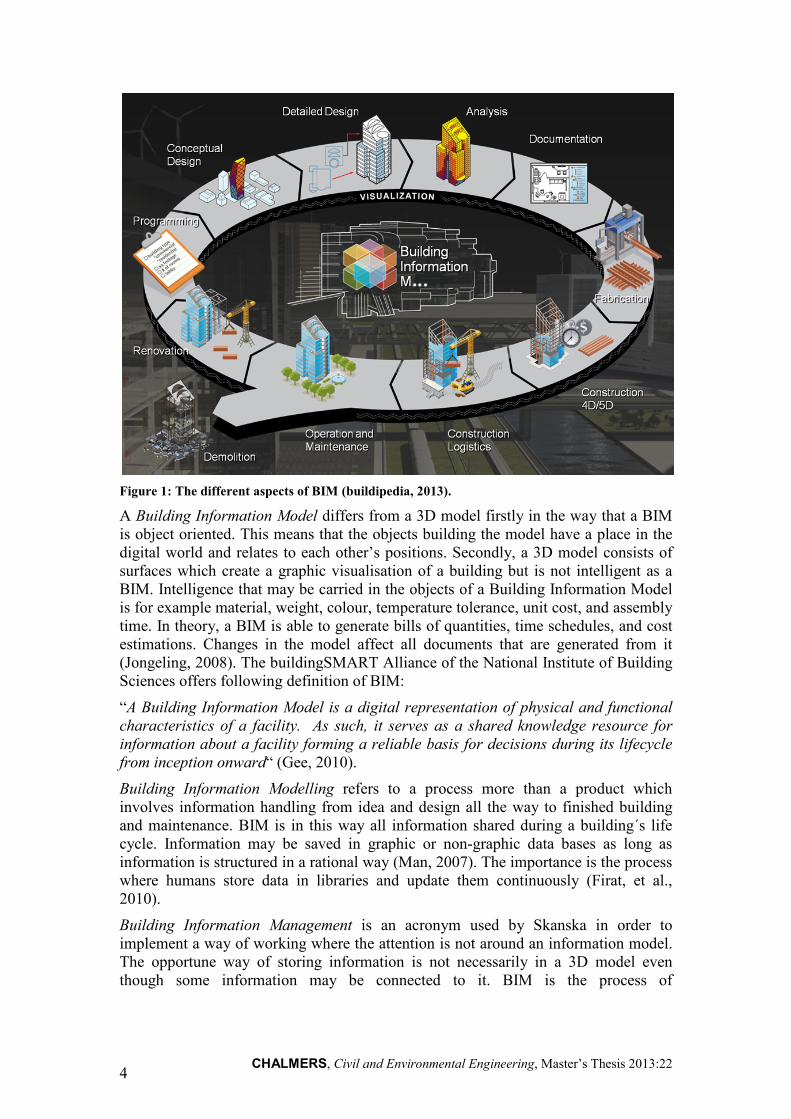
The meaning of the acronym BIM has been widely discussed since its introduction (see Figure 1). Three different translations are commonly used which are Building Information Model, Building Information Modelling, and Building Information Management.
CHALMERS, Civil and Environmental Engineering, Master’s Thesis 2013:22 4
Figure 1: The different aspects of BIM (buildipedia, 2013).
A Building Information Model differs from a 3D model firstly in the way that a BIM is object oriented. This means that the objects building the model have a place in the digital world and relates to each other’s positions. Secondly, a 3D model consists of surfaces which create a graphic visualisation of a building but is not intelligent as a BIM. Intelligence that may be carried in the objects of a Building Information Model is for example material, weight, colour, temperature tolerance, unit cost, and assembly time. In theory, a BIM is able to generate bills of quantities, time schedules, and cost estimations. Changes in the model affect all documents that are generated from it (Jongeling, 2008). The buildingSMART Alliance of the National Institute of Building Sciences offers following definition of BIM:
“A Building Information Model is a digital representation of physical and functional
characteristics of a facility. As such, it serves as a shared knowledge resource for
information about a facility forming a reliable basis for decisions during its lifecycle
from inception onward“ (Gee, 2010).
Building Information Modelling refers to a process more than a product which involves information handling from idea and design all the way to finished building and maintenance. BIM is in this way all information shared during a building´s life cycle. Information may be saved in graphic or non-graphic data bases as long as information is structured in a rational way (Man, 2007). The importance is the process where humans store data in libraries and update them continuously (Firat, et al., 2010).
Building Information Management is an acronym used by Skanska in order to implement a way of working where the attention is not around an information model. The opportune way of storing information is not necessarily in a 3D model even though some information may be connected to it. BIM is the process of

CHALMERS, Civil and Environmental Engineering, Master’s Thesis 2013:22 5
communication and information sharing within a project, including information not connected to the model (Velén, 2013).
Objects created in a building information model are described by the software in three different ways; structural description, functional description, and graphic description (Mikael Bengtsson & Frank Jauernig, 2008).
• Structural description – indicates what the object consists of, for example what materials are included in a wall or that a door has elements as doorframe, leaf, and hinges.
• Functional description – indicates how the object should function, a door for example makes a hole in the wall and is able to open.
• Graphic description – indicates what the object looks like, meaning the 3D visualisation that consists of surfaces (Mikael Bengtsson & Frank Jauernig, 2008).
The difference between a CAD-object and a BIM-object is that a CAD-object is only described by the graphic description. When the graphic description is connected to the structural and functional description the CAD-object becomes a BIM-object (see Figure 2) (Viklund, 2010).
Figure 2: Illustration of the difference between a CAD-object and a BIM-object
(Mikael Bengtsson & Frank Jauernig, 2008).
2.4 The use of BIM
BIM has several areas of use including 3D visualisation, clash detection, production planning, and cost estimation.
2.4.1 3D Visualisation
As mentioned, a 3D model is not automatically a BIM. However, producing a Building Information Model automatically results in a 3D visualisation of the building (see Figure 3). In other words, a 3D model is a by-product of BIM design which

CHALMERS, Civil and Environmental Engineering, Master’s Thesis 2013:22 6
means that in a BIM project no money has to be spent on 3D visualisation. BIM tools often include functions for 3D presentations as textures, lightning, and view ports. Technology is based on gaming software which makes the user able to walk around in the common model giving clients and designers opportunity to get to know the building even before production starts (Jongeling, 2008).
Figure 3: 3D visualisation from the inside of the reference project.
2.4.2 Clash Detection
Different parties design different parts of a building and it is important that all construction parts fit together. When designing in 2D it is difficult to get a picture of how different building parts and systems will work together. Working with BIM enables 3D visualisation for better coordination among designers (see Figure 4). There is a number of different software that includes tools for this purpose; most commonly used name of such a tool is clash detection meaning that a BIM coordinator will be notified if any construction parts overlap (Jongeling, 2008).

CHALMERS, Civil and Environmental Engineering, Master’s Thesis 2013:22 7
Figure 4: Collaboration control of installations in the reference project.
2.4.3 4D BIM, 3D + time
When talking about BIM the fourth dimension is often mentioned, 3D + time. By hiding and revealing objects at a certain point in time it is possible to make a simulation of a project to see what the production will look like. Using tools for 4D planning makes it easy to visualize schedules and the planned work (see Figure 5) (Man, 2007).
Figure 5: 4D simulation in Vico Software (Vicosoftware, 2013).

CHALMERS, Civil and Environmental Engineering, Master’s Thesis 2013:22 8
2.4.4 5D BIM, 3D + time + cost
The fifth dimension of BIM is often connected to cost control. Linking quantities in a model with a cost database makes it possible to generate a cost estimation of a project automatically. The cost estimation will then be dynamic which means that if something changes either in the model or the cost database the cost estimation will also change (Man, 2007). The easiness of BIM-based cost analysis gives opportunities to test different designs or material options to see which are most beneficial (Gee, 2010). Moreover, the connection to time enables real time cost control giving managers opportunity to follow costs as a project develops (Man, 2007).
2.5 Interoperability between Different Software
BIM is all about information and information has to be communicated. In construction communication often need to take place between different parties in a project. Different parties may work for different companies using different information systems and software which creates an interoperability problem as different software may define information differently (Man, 2007). It does not make sense to create a BIM if it is not possible to reuse the information in other software than where information was first created (Gee, 2010). IAI, the International Alliance for Interoperability has defined a standard file format for Building Information Models called IFC, Industry Foundation Classes. Using this standard makes it possible to move, change and exchange information between different software (see Figure 6) (Man, 2007).
Figure 6: Visual description of IFC (Kiviniemi, 2013).
The IFC format is built up by a modular scheme with a four class structure:
• Resource Layer
• Core Layer
• Interoperability Layer
• Domain Models Layer (Man, 2007)

CHALMERS, Civil and Environmental Engineering, Master’s Thesis 2013:22 9
This means models may be converted to IFC to be exchanged with other software without losing their intelligence. However, a standard format is built upon lowest common denominator which means some information will be lost in the conversion. The purpose of IAI is to work with IFC to continue its development (Man, 2007). IAI hope that with IFC different parties within a construction project will be integrated by building information rather than drawing data (Kiviniemi, 2013).
2.6 Usage of BIM in Other Nordic Countries
The development of BIM technology has been more and less successful in different Nordic countries and it is argued that Norway, Denmark and Finland are several years ahead of Sweden considering BIM implementation in the construction industry (Wong, et al., 2009). In Finland for example, common BIM guidelines have been developed by buildingSMART in order to unify ways of working throughout the country (buildingSmart, 2013).
2.6.1 A Brief Summary of Quantity Takeoff Guidelines in Finland
Most important when using the model for quantity takeoff is consistency and one of the key concepts is consistency in nomenclature. There are several different standards in naming objects in a BIM and which definition to use must be agreed upon when starting up a project. Furthermore, it must be agreed upon from what discipline certain building elements should be taken off from, one example being if slab area should be taken off from the construction model or the architectural model (buildingSmart, 2013).
Total quantities are calculated by adding measurements of single objects together. Because of this, it is important that every object in the BIM is individually identifiable. Most commonly used measurements are; number of pieces, length, height, perimeter, net surface area, gross surface area, net volume, gross volume, net weight, and gross weight (buildingSmart, 2013).
A lot of difficulties in quantity takeoff occur when the BIM is not modelled according to agreements or if modelling is not done in the same way throughout the entire model. However, it is possible to vary the level of detail if the different levels of detail are clearly specified in a BIM manual. Everything depends on what the model is going to be used for, in some cases only object geometry is needed and in other cases even rebar weight is required. Furthermore, it is important to use BIM tools compatible with quantity takeoff purposes. A wall should be modelled by a wall tool and a roof should be modelled by a roof tool (buildingSmart, 2013).
2.7 Two ways of using a BIM to estimate costs
There are primarily two different ways of applying model-based quantity takeoff in estimating; semi-automatic and automatic. Using a semi-automatic approach means that the estimator has two screens, one showing the 3D model and the other one showing construction parts that need to be quantified. The estimator uses the 3D model to mark certain construction parts to get the quantity. This number can then be put into the corresponding field on the other screen. In this way, the estimator has full

CHALMERS, Civil and Environmental Engineering, Master’s Thesis 2013:22 10
control of what happens using the model as a measuring tool (Mikael Bengtsson & Frank Jauernig, 2008).
The second approach, automatic quantity takeoff means that the BIM is connected to the cost estimation and quantities are automatically presented in the cost estimation. This is a much faster method but many people that have worked with this method feel they lose control of what is happening (Mikael Bengtsson & Frank Jauernig, 2008). However, using BIM technology the time of the quantity takeoff process may be reduced by up to 80 per cent (Viklund, 2010).

CHALMERS, Civil and Environmental Engineering, Master’s Thesis 2013:22 11
3 Method
In this chapter the methodology of conduction this master thesis is described. Furthermore, the reference company, the reference project, and the people interviewed are presented along with thesis limitations and extensions beyond limitations.
3.1 Methodology
The methodology used in this master thesis is a Design Science Research. In this kind of research people, organisations and technology are studied in an existing environment. A knowledge base of models, instruments and methods are applied on the existing environment and developments are evaluated and justified (see Figure 7). In other words, business needs and applicable knowledge are brought together on an organisation and an iterative process of developing and evaluating new ways of working results in organisational progress (Hevner, et al., 2004).
Figure 7: Design Science Research framework (Hevner, et al., 2004).
This master thesis started by studying relevant literature on the subject and continued with five weeks of field observations on a reference project managed by a reference organisation, Skanska. Production managers, BIM consultants, and other practitioners of interest were interviewed and results were analysed. Interviews have been semi-structured with open questions and all interviewees have been given the chance to correct any misunderstandings written in the report before printing. By trying alternative work methods doing quantity takeoffs from a BIM current ways of quantifying have been iteratively improved. An analysis has been made considering literature and interview results and solutions for work process improvement are presented along with academic reflections. Primarily, this master thesis aims at

CHALMERS, Civil and Environmental Engineering, Master’s Thesis 2013:22 12
production quantities in facilities and residential projects and focus has been on quantities needed for a general contractor and works related to core complements.
3.2 Company Presentation of Skanska
Skanska is a Swedish construction company working on chosen markets in Europe, USA, and Latin America. The company has 53000 employees, 11000 of them located in Sweden, and a global turnover of 123 billion SEK a year. This makes Skanska the largest construction company in Sweden and even one of the largest construction companies world-wide (Skanska, 2013).
3.2.1 Organisation
On the Swedish market Skanska has operations in:
• Construction
• Residential Development
• Commercial Property Development
• Infrastructure Development (Skanska, 2013)
Skanska is divided into a number of different regions and a number of different support functions, one of the support functions named Skanska Teknik (Skanska, 2012).
3.2.2 Skanska Teknik
Skanska Teknik is a strategic resource within Skanska being a support function with competence within all of Skanska´s areas of operation. Skanska Teknik has 300 employees divided into four different departments; Building engineering and Design, Civil engineering and Design, Road Technology, and BIM (Skanska, 2012).
The department of BIM at Skanska Teknik focuses on BIM development and implementation within Skanska Sweden. The aim is to develop BIM both in ongoing Skanska projects and in future projects by introducing new work processes, new tools for usage of BIM technology, and to lift out beneficial examples of BIM projects (Skanska, 2012).
In large Design-Build contracts Skanska Teknik offers a standard BIM-package with 3D design and 3D coordination. A model is built in the design phase where all involved disciplines are coordinated. The model may be used as a source of information throughout the entire project and is connected to material, quantities, and production methods (Skanska, 2012).
3.3 Reference Project Tändstickan
Tändstickan is the primary reference project this master thesis is based on. The project is a facilities project located in the centre of Göteborg, total cost being approximately 350 million SEK (see Figure 8) (Pettersson, 2013).

CHALMERS, Civil and Environmental Engineering, Master’s Thesis 2013:22 13
Figure 8: Project Tändstickan.
3.3.1 Basic Information
During 2012 and 2013 Skanska is building a 17 store office building, Skanska being both Client and Contractor. The building will have 20 000 m² of rentable area of which the primary tenant ÅF already signed a contract for half of it. Next to the office building Skanska is also building a car park with 400 spots (Pettersson, 2013).
The core is made by a prefabricated concrete structure with a steel body and hollow core slabs, columns are filled with concrete for fire safety reasons. The foundation is built on site standing on piles connected to the mountain underneath. Total building time of the core was set to 25 weeks which was accomplished thanks to well managed logistics (Pettersson, 2013).
Skanska has chosen to get the building LEED Platina certified, their third building in Göteborg meeting those demands. Facades are key factors and a lot of focus has been on lowering sound levels, increasing transmission of light, optimizing energy consumption, and finding an exciting architectural solution (Pettersson, 2013).
3.3.2 BIM Design
Project Tändstickan is designed with support of Skanska Teknik, standard BIM package with 3D model and collaboration control being used. All designers have been obliged to follow requirements printed in a CAD manual on how to model their own sub-model. Software to use, file formats, object names, and floor height coordinates have been specified and agreed upon by all parties involved in the design (Thorell, 2013). However, since the common model is not used for quantity takeoff in

CHALMERS, Civil and Environmental Engineering, Master’s Thesis 2013:22 14
production no effort has been put on controlling that objects are named accordingly (Montecinos, 2013).
3.4 Presentation of Interviewees
Following people have been interviewed within their area of expertise:
• Martin Stridh, site manager at Skanska (reference project)
• Mikael Johansson, production manager at Skanska (reference project)
• Jonas Högberg, production manager at Skanska (reference project)
• Camilla Pettersson, production manager at Skanska (reference project)
• Henrik Bjurström, internal purchaser at Skanska (reference project)
• Joel Liedbergius, BIM coordinator at Skanska
• Ulf Thorell, BIM coordinator at Skanska
• Carlos Montecinos, BIM coordinator at Skanska
• Robert Velén, BIM developer at Skanska
• Håkan Norberg, BIM consultant at PlanB
• John Fahlgren, BIM coordinator at Ramböll
• Hanna Skånberg, BIM coordinator at Skanska
• Börje Westerdahl, Researcher at Chalmers University of Technology
3.5 Limitations
This master thesis focuses on production quantities in residential and facilities projects only. Moreover, when managing actual quantities in the reference project only Solibri Model Checker has been used as reviewing software.
3.6 Extensions beyond Limitations
Estimation quantities are strongly connected to production quantities and for this reason work processes in estimation have also been taken into consideration. Moreover, one bridge construction project has been studied because it is the only project in Sweden where the BIM is the legally binding document.

CHALMERS, Civil and Environmental Engineering, Master’s Thesis 2013:22 15
4 Compilation of Interviews
In following chapter all results from interviews have been summarized and are presented as a continuous text. Although, some basic facts have been collected from websites and are also presented in this chapter.
4.1 Different Kinds of Software Using BIM Technology
The usage of BIM technology is based on advanced software handling the model in different ways. There are different software to create, view, and review the model and expense varies depending on software features (Fahlgren, 2013). In following chapter the different kinds of software along with commonly used brands in Sweden are presented.
4.1.1 Software for Modelling
In practice, creating a model means putting objects from a library into a workspace. Different parties such as architects, construction engineers, and installation system designers use different software due to their individual requirements when designing. The different software on the market has slightly different features and it is important for all users to know possibilities and limitations of the software they use (Montecinos, 2013). Most commonly used software among architects are Autodesk Revit Architecture and ArchiCAD, among construction engineers Autodesk Revit Structure and Tekla Structures, and among installation designers Autodesk Revit MEP and MagiCAD which are add-ins to Autodesk Revit and AutoCAD (Fahlgren, 2013).
4.1.2 Software for Collaboration Control
A BIM most often consists of several different sub-models. For this reason, it is important to check that all sub-models are compatible with each other. In most contracts it is the contractor´s responsibility to review the sub-models in a common coordinate system, usually done by clash detection features (Thorell, 2013). Most commonly used software used are Solibri Model Checker and Navisworks Manage (Fahlgren, 2013).
4.1.3 Model Viewers
Advanced BIM software is very expensive and for this reason most developers also have a basic free viewer. A viewer works like a reviewing software but lacks most features such as clash detection and quantity takeoff. It is simply a way to visualize all sub-models in the same coordinate system without being able to change or check the common model. Most commonly used software are Tekla BIM-sight, Navisworks Freedom, and Solibri Model Viewer (Fahlgren, 2013).
4.1.4 Software for Quantity Takeoff
There are different kinds of software that enables quantity takeoff. First kind is reviewing programs that have built in functions for quantity takeoff, one example

CHALMERS, Civil and Environmental Engineering, Master’s Thesis 2013:22 16
being Solibri Model Checker. The second solution is a small add-in program that enables functions for quantity takeoff in software that initially does not have that feature, one example being Tocoman I-Link that may be used in Autodesk Revit Architecture or Structure. Another way to do quantity takeoff is to use functions in the modelling software which some of them have built-in (Westerdahl, 2013).
4.1.5 Integrated Systems
In integrated systems not only functions for collaboration control and quantity takeoff are enabled, when for instance quantities are linked to recipes the system generates dynamic cost estimations. Moreover, using the quantities to generate time schedules makes users able to create 4D simulations of the project by linking models and schedules together. Built in functions for production control and client reporting makes integrated systems handling the entire building process, all information connected to the model (Vicosoftware, 2013). Vico Office and Tocoman EasyBIM are examples of such software (Norberg, 2013).
4.1.6 PDF viewers
PDF viewers are software not using BIM technology but manage PDF files and digitalize quantity takeoff. The software makes it possible to measure, mark, search, compare, integrate, and link different drawings. Automatic consideration of scale makes measuring extremely easy compared to the old work process where measures are taken off a physical piece of paper (Bluebeam, 2013). Most commonly used software is Bluebeam Revu eXtreme (Fahlgren, 2013).
4.2 BIM Implementation
BIM is closely related to information technology which is essential in any business. In estimating, the level of IT knowledge is considerably high and there have been requests about better tools and software to work with, in this way forming kind of a pull system where demand comes from estimators. In production, there has not been such a requirement from production personnel leading to that more of a push strategy has been applied to implement new information technology. One reason may be that the level of IT knowledge of production personnel is considerably low compared to estimators, consequence being that production personnel do not know what to ask for. To implement new technology there have to be someone in the unit that is interested in the subject in order to find new ways of working (Liedbergius, 2013).
It has been tried to implement BIM technology in different stages of construction but with not much results, starting to use BIM has to start already in the design phase. Today, the desire to use BIM is often pointed out by the client or contractor. Architects do not have any interests in putting a lot of information in a model for others to use unless they are getting paid for it which means that requirements of BIM usage have to be specified in a contract. In order for a contractor to form a contract of this kind there need to be a kind of contract that gives the client or contractor possibility to govern the designers, example being a Design-Build contract (Norberg, 2013). In Finland for example, demands have already been implicated by the state

CHALMERS, Civil and Environmental Engineering, Master’s Thesis 2013:22 17
which means contractors do not have to spend time and effort on BIM marketing (Fahlgren, 2013).
Software is very expensive and a small or medium sized project is not able to afford a single license cost of several thousand Swedish crones. Many software developers such as Autodesk, Tekla, and Solibri have developed free viewers as complements to their full version programs. As mentioned, a clash detection may be run on the common model in a full version reviewing software and then simply viewed for free by people on site. However, when doing quantity takeoff the full version is needed for most software (Fahlgren, 2013). It is argued that costs for licenses is too great and quantifying on drawings in production are cheaper even though the amount of time needed is considerably more (Stridh, 2013). However, there are other ways to provide projects with software without putting a full license cost on the project. Projects may simply rent network licenses from a pool of licenses that are paid for centrally on a yearly basis which will make software available on site much cheaper (Fahlgren, 2013).
Depending on the size of a project the work with BIM looks different. In small projects, there are not enough resources to have a BIM coordinator at site. This means that someone in the office is producing a lot of results that must be sent to production since this person is the only one in possession of required software and knowledge (Fahlgren, 2013). Moreover, production may start even though there are very few documents finished, including a usable BIM (Stridh, 2013). In many cases, some sub-contractors and suppliers are not even involved in the project yet when production starts (Skånberg, 2013)
Navigating in software for 3D visualisation is something that must be learned. It takes some time to get used to all functions that make the user able to move around in the model. Nowadays, most engineering students have tried some software for 3D visualisation and therefore manage to navigate in any similar software distributed at site. Many production managers of today though have no experience of this kind of software and just learning to navigate in a 3D model require both education and time (Stridh, 2013). On the other hand, working with BIM for quantity takeoff is a much more exiting way to work compared to the old fashion way of measuring on a physical drawing. Changing work processes for quantity takeoff may attract more people wanting to work with quantity-related services, implementation being profitable in a long term-perspective anyway (Liedbergius, 2013). Moreover, more exiting work processes improve the dedication of personnel already employed which increase both effectiveness and efficiency (Skånberg, 2013).
Today, drawings are the legally binding document which becomes a huge barrier for the implementation of BIM. Production personnel cannot use the BIM, if something gets wrong then the first question raised is: Was measuring done in the model or on drawing? If the answer is “the model” no compensation may be claimed due to design errors. Moreover, the CAD manual is not a legally binding document either and today all information about how modelling should be done is in the CAD manual (Stridh, 2013).
There is only one project in Sweden where the BIM is legally binding and the client has even put incentives not to use any drawings on the project. In this way, designers and production personnel have been obliged to work closer together in order to get the BIM usable in production. Making them to do so may be a good way to find better ways to pass on information to the next project stage. Furthermore, development cost

CHALMERS, Civil and Environmental Engineering, Master’s Thesis 2013:22 18
money and it is important for organisations to have pilot-projects where focus is not primarily on profit but on trying new ways of working (Skånberg, 2013).
Implementation of model-based quantity takeoff must be done in several steps. It is the responsibility of the project BIM coordinator to ensure that tools and software are not only available in production but also that personnel have enough knowledge to use them. One way to teach production personnel how to do quantity takeoff may be to first deliver wanted quantities along with pictures and screen shots. The next step would be to deliver the quantities but to let production personnel visualize the quantities in a model viewer. Finally, quantity takeoff may be done with only the supervision of the BIM coordinator. The downside of this implementation method is that quantifying material does not indirectly result in learning the project. On the other hand, the first two steps do not cost the project anything in terms of software licenses (Fahlgren, 2013).
4.3 Different Ways of Modelling
Modelling may be done in several different ways depending on who is doing the modelling and what software is used. According to COBIM a floor should be modelled by a floor tool but this is done very differently in for example Graphisoft ArchiCAD and Autodesk Revit Architecture. Moreover, if emphasis is on using the BIM for energy consumption analysis walls must be attached to the slab whereas if the BIM will be used to extract paint quantities the wall should be attached to the ceiling (Fahlgren, 2013).
Not everything that is built on a project is part of the final product. Temporary constructions as work platforms and access routes are needed daily and whenever any casting is made formwork has to be put up. Formwork quantities may in most cases be taken off the modelled concrete structure but some temporary constructions are beneficial to model in order to get wanted quantities in an easier way (Skånberg, 2013).
It is important to have a manual for how the architect should model, but it is also important to have a manual for how the model should be used. Production personnel need to know how they should do quantity takeoffs, if it is decided that information about door lining should be found in the door object in the BIM then production personnel needs to know that it should be found there. CAD manuals have been used for several years and this new type of description is called a BIM manual. The BIM manual should also define how objects are numbered, how objects are named, and what attributes have been quality assured (Norberg, 2013). Furthermore, some building parts are modelled by several parties. For example, a slab or an exterior wall is often modelled by both an architect and a structural designer. Depending on what kind of object is modelled it is done with different level of detail. Not only should it be clearly stated in a BIM manual what objects are modelled twice but also what discipline to use when doing a quantity takeoff (Fahlgren, 2013).
A good way to define what parameters should be used in a project´s BIM is to look at the lowest common denominator between used software and IFC. Values are organized by different parameters in different modelling software and integrating all parameters in a common model often cause problems. If using the IFC format all parameters must be translated in the same way from both mother software used, convenient way of working being to agree upon a list of lowest common denominator.

CHALMERS, Civil and Environmental Engineering, Master’s Thesis 2013:22 19
However, getting lists of all possible parameters comparing them to those of IFC is not very easy, producing such a list is also very time consuming (Norberg, 2013).
There are different ways to model object sizes, but to model information may also be done in different ways. Today, most information connected to the BIM is stored in the objects building the model. Objects will most likely in the future be almost empty only defined by the littera they are given. Information about the specific object may be found in a separate document connected to the littera it represents. In this way, the model does not have to be sent back to the designer every time changes need to be done in the model. One cannot expect that designers will put exactly the right information into the model from the beginning, best way would be to model an empty object only defined by functional characteristics. Furthermore, if information is found in linked documents it will be easier to continuously put more information into the project as new information develops. This may even be done jointly by all designers that have new information to update the BIM with (Fahlgren, 2013).
4.4 Interior Walls; the way production manage them
today
There are a number of different walls in a project. Interior walls are often made on site partly by measuring, cutting, and mounting gypsum boards. Gypsum boards are ordered by production management and the process of quantifying the amount of material is very time consuming. Quantifying of material for interior walls alone was in the reference project done over two to three weeks, according to a Skanska production manager gypsum is one of the most time consuming building parts to quantify in a facilities or residential project (Johansson, 2013).
One of the main reasons that material for interior walls is complicated to quantify and build is the amount of different wall types. The more wall types that are specified in a project the more difficult it gets to keep track on how each wall should be built, each wall type is defined in a separate wall table (see Figure 9). One action to keep the number of different wall types at a minimum is to generalize some of them separating them on another description. For example, there could be a text in the specifications saying that all interior walls screening off a room containing a floor drain should have a bathroom slab mounted on it. In this way, two walls may be defined by the same wall type even though they are built differently (Stridh, 2013).

CHALMERS, Civil and Environmental Engineering, Master’s Thesis 2013:22 20
Figure 9: Table of wall types in the reference project.
The process of quantifying interior wall material was in the reference project introduced by printing all necessary drawings. Different types of walls had to be sorted out since there were twelve number of different types, wall type is presented on the drawing next to the wall connected to it (see Figure 10). Usually each wall type is marked with a coloured pen making it easy to visually separate different types when measuring the quantities. Measuring was done using a scale bar and measurements were added together on a piece of paper, every measurement rounded up to whole meters (see Figure 11). Sums where then written into an XML document to be further added together (Johansson, 2013).

CHALMERS, Civil and Environmental Engineering, Master’s Thesis 2013:22 21
Figure 10: Plan view drawing in the reference project where wall types are presented.
Figure 11: Current method of quantifying material for interior walls in the reference project.
The next step was to look at the wall specification; different types of walls have different amounts of gypsum layers, different types of rails, different thickness of isolation, and different types of studs. The wall types are dimensioned according to required sound level, even though the height of the walls differ. Gypsum boards may be ordered in different sizes and to make sure waste is at a minimum it is important to order sizes that may fit together. This means the production manager quantifying

CHALMERS, Civil and Environmental Engineering, Master’s Thesis 2013:22 22
gypsum boards need to consider wall height into his or her calculation (Johansson, 2013).
The result is a table sorted in wall types and heights with all quantities connected to each row. Depending on the supplier´s ordering system gypsum may be ordered as meter, square meter, or amount of packages. By knowing the area or length of every wall type of a certain height rails, isolation, and studs are easily calculated. Isolation is often ordered in the same amount as wall area, rails and studs are ordered per meter wall. On each regular floor the total amount of gypsum for interior walls was by hand calculated to 780 square meters in the reference project (Johansson, 2013).
When quantifying the amount of material needed to build the interior walls there have been some complications. Defined wall types could not be trusted because even though two walls have the same name the composition may differ depending on where the wall is located. For example, two walls both named “IV05” have in one location consisted of four layers of gypsum and on another location only two layers. Some walls have even required a special kind of gypsum even though this is not presented on the drawing (Johansson, 2013). However, if a project is planned accordingly all interior walls that require another kind of gypsum should be defined by their own wall type (Stridh, 2013).
There are a number of downsides with the current way of working. Firstly, quantifying gypsum is very time consuming. If the BIM would have been trustworthy the responsible production manager could have joined the project three weeks later according to himself. Secondly, human error is a huge risk and quantifying is often done several times to decrease the uncertainty of the calculation. Production managers feel unsecure up until the time of material arrival which in many cases are several weeks (Johansson, 2013).
Work methods among production managers are often individual, each project are managed differently depending on who manages it. For example, in a former project the current site manager at Tändstickan used an alternative method to cut gypsum boards for interior walls. Boards were ordered according to wall height and cut off completely at every opening (see Figure 12). To fill the space between the roof and doors another dimension of gypsum boards were ordered, method being used to keep material waste at a minimum. Using a BIM for quantity takeoff in this situation would have resulted in area calculations not compatible with the production method (Stridh, 2013).

CHALMERS, Civil and Environmental Engineering, Master’s Thesis 2013:22 23
Figure 12: Alternative way to cut gypsum boards.
4.5 Doors; how they are ordered in a project today
Doors are an essential building part in all facilities and residential projects and there are often a variety of different types. Door types are organized in a table according to a number of properties such as hanging, execution, component, way of opening, dimensions, timber class, functional requirements, covering, frame, and lining (see Figure 13). The door table is first used by an internal purchaser to get a price from a supplier of the required doors specified (Bjurström, 2013). When the purchase is done production personnel need to require delivery of doors, often done by floor or else everything in the same delivery. When the doors are delivered production managers want to control that all products and items have arrived according to the door table (Johansson, 2013), door table is in the first place made by the architect (Bjurström, 2013).

CHALMERS, Civil and Environmental Engineering, Master’s Thesis 2013:22 24
Figure 13: Door table in the reference project.
Since the door table have already been made when production starts production personnel do not need to quantify what doors they want to have delivered. If everything is working out accordingly production managers only need to say when they want the door delivery, worst case they need to send the door table to the supplier (Högberg, 2013). However, production personnel need to check the delivery to make sure everything is delivered in the way it was required. The door table needs to be translated into a bill of quantities which means all items included have to be counted by hand. Translating the door table takes time and model-based quantity takeoff would have been very useful (Johansson, 2013). Furthermore, when the doors and frames are delivered at site they need to be placed in the room they should be

CHALMERS, Civil and Environmental Engineering, Master’s Thesis 2013:22 25
mounted in. Packages are not sorted by door type but by item which means doors and frames need to be paired together. Production personnel need to check the drawings and make a list of what doors and frames goes in each room (Johansson, 2013).
There is quite often mistrust to all documents that are not drawings. In many cases production managers want to control that what is on the door table is consistent with what is on the drawing, doors being a building part that in many cases tends to get wrong (Johansson, 2013). Information needed in the model is basically the same information as in the door table (Högberg, 2013). According to another production manager however, properties that needs to be controlled is primarily dimensions, hanging, material, and colour (Johansson, 2013).
Door lining and handles are often ordered separately from doors and frames (Johansson, 2013). Production managers need to control extra carefully that what arrives is really what has been ordered. Making a bill of quantities are made again by counting on the door table what items should be delivered, door lining is often ordered in standard lengths, 220 mm. In the same way as doors and frames, door lining and handles need to be paired together and put in the right room (Johansson, 2013).
4.6 Areas of Ceilings and Slabs
In the reference project ceiling is ordered by Skanska´s production management. Quantities are often measured using scale bar and calculator, result being put into an excel document. Some members of the production personnel use PDF tools such as Blue Beam which removes the work of scaling and printing. Furthermore, the software enables area functions which reduce the amount of measurements needed. Moreover, whenever an invoice arrives it needs to be controlled. Invoices are often based on quantities and since it is time consuming to measure areas and volumes on drawings this action is often neglected. For example, if a construction worker tells production management he wants to get paid for a certain amount of filler the amount of filler needs to be controlled. If there would have been an easier way of getting the actual quantities this invoice could have been controlled more closely (Johansson, 2013).
4.7 Internal Purchaser and his Work with Quantities
On big projects there is often a purchaser working in production. There are a lot of building parts and work that need to be purchased and drawings are basis for inquiries. This means purchasers never have to make bills of quantities prior to sending out inquiries. However, suppliers often ask for quantities and they are sometimes attached to the specification as a help when determining a price. Furthermore, an invoice does not give very much information so purchasers often want to control that the right quantities are calculated for when the invoice arrives. Quantities mostly calculated are areas (Bjurström, 2013).
Unlike production managers purchasers often quantify other works than are presented on the architectural drawing, pipes and ventilation are commonly counted for. However, purchasers only need to make very rough quantity estimations since price almost always is determined by actual quantities rather than measured quantities presented in the specification. Moreover, an inquiry is often sent to several different suppliers. They all quantify the work and material needed in order to send back a

CHALMERS, Civil and Environmental Engineering, Master’s Thesis 2013:22 26
price suggestion. There are many cases where the quantities being sent back differ a lot between different suppliers, they all count differently. The natural thing to do for a purchaser is then to quantify the material by himself in order to get a reference number to work on. Again, information may be taken from an early estimator´s bill of quantities but this number is rarely trusted, meaning the purchaser needs to calculate the quantities in a traditional way using drawings (Bjurström, 2013).
4.8 Financial Status of a Project
Four times a year every project needs to report its financial status. This work is done by using the same method as cost estimators do when calculating a project, quantities are connected to costs. At the reference project a financial status was delivered recently and one production manager was dedicated to this task for two weeks. The amount of time for quantifying used and bought material was approximately 40 per cent of this time. When estimating the financial status calculating is done very roughly and model-based quantity takeoff with the BIM would have been very useful (Johansson, 2013). An ideal way of working would have been to have both time and cost connected to each object in a BIM. Being able to follow costs as the project evolves gives production management control of project profitability (Skånberg, 2013).
4.9 Room Descriptions
When designing using drawings it is neither possible nor realistic to draw all information needed for the project. Room descriptions have been used for several years to specify what components that are not visible on drawings should be mounted in a room, a few examples being wall papers, bath room mirrors, and skirting boards (Johansson, 2013). Using BIM is no difference and it is not rational to model every single detail in a project which means that some information must be kept in room descriptions anyway, most important when placing information in the BIM is to be consistent (Norberg, 2013). Which information goes where needs to be defined in the beginning of a project. Some information is better to store in building elements and other information in room descriptions. For example, wall finish is more rational to specify in a room description than in the wall object in BIM. Firstly, a wall has two sides often with two different finishes. Secondly, one wall may be present in two different rooms which make modelling complicated if information about finish is kept in the building element (Norberg, 2013).
4.10 Spaces in BIM
There are two different physics modelled when working with a BIM; Building elements and Spaces (see Figure 14). A space is a modelled volume defined by building parts around it such as walls, floors, ceilings, and roofs (Norberg, 2013). When using spaces for quantity takeoff in production it is important how the dimensions of the space are defined. Standard legal specifications allow designers to make their measurements from wall centre to wall centre when presenting an area of a room. However, when calculating the area of a floor finish or the length of skirting boards being mounted in a room measuring must be done from wall inside to wall

CHALMERS, Civil and Environmental Engineering, Master’s Thesis 2013:22 27
inside. For this reason, demands have to be put on designers in a legally binding document in what way measurements must be done (Stridh, 2013). Moreover, room height must also be defined correctly and the question is what dimensions should be chosen. Interior walls are sometimes connected to the ceiling, leaving a volume above for installations (Norberg, 2013). On the other hand, walls sometimes are connected to the slab if sound requirements are higher than usual (Johansson, 2013).
Figure 14: The difference between building elements and spaces in a BIM in the reference
project.
Today there are some complications using spaces in a model, one problem is connected to the software. Spaces are not fully developed in all software, Graphisoft ArchiCAD being the one having adapted it in the best way. Moreover, when exporting spaces to the IFC format standards are not fully developed for the conversion of data. This creates a problem for the receptor because information gets reorganized and may then differ from the agreed structure (Norberg, 2013). A second problem is that the sides of a space are not individually identifiable. If the area of only one side of the space is needed this quantity is not easy to extract (Fahlgren, 2013).
Production personnel already talks about different belongings. For example, gypsum belongs to a wall while skirting boards belongs to a room. Wall paper belongs to a wall while glazed tiles belong to a room. Door lining belongs to a door and the door could either belong to a room or a wall (Johansson, 2013). Furthermore, several different wall finishes may be found on one wall but there will never be two different wall compositions in one wall if designed correctly (Johansson, 2013). Moreover, building elements may be connected to a space in the model. For example, wardrobes may not only be located by coordinates and floor but also in what room they should be put in (Norberg, 2013).

CHALMERS, Civil and Environmental Engineering, Master’s Thesis 2013:22 28
5 Analysis of Results Based on Model
Experimenting and Interviews
Simultaneously with interviews there has been experimenting with a BIM from the reference project in order to understand the complications of model-based quantity takeoff. In following chapter an analysis of previous chapters are presented where theoretical background, interview results, and model experimenting are brought together by the author.
5.1 BIM Implementation
Going from manual quantifying on drawings to doing quantity takeoffs from a BIM is a huge step to take and there are few practitioners in production that are ready to entirely change their way of working. Companies trying to introduce the BIM as a new source for quantities need to systematically take small steps not changing work processes to much in each step. Moreover, software expenses are one of the most common arguments not to implement BIM in production and many practitioners are not aware of other solutions than putting the entire cost of single licenses on a project.
Pushing new work methods out in production does not work if there is no demand from production personnel. Production managers are not interested in changing their way of working unless they see what benefits a new work method brings. Furthermore, production managers cannot require any new technical tools if they do not know the possibilities with them. In some way the organisation need to get production management to actively require better tools and ways to quantify material. On the other hand, forcing employees to work in ways they have never done before creates innovation.
5.2 Way of Modelling
In the reference project, the model is not used for quantity takeoff in production so no time and money have been spent on controlling that the model actually only contains construction element names from the agreed list in the CAD manual. The consequence has been that names are not consistent and there is a huge risk of missing elements when doing quantity takeoff from the model. A list of agreed names may either be imported to Solibri Model Checker from Microsoft Excel or created in Solibri Model Checker to be exported to Microsoft Excel. However, there is no export-button in Solibri Model Checker so information has to be copied and pasted into Microsoft Excel which may feel like an unprofessional way of working. Requirements of an export-button for a created rule have been sent to Solibri and response has been sent back.
In most software for modelling there are different tools for creating walls, slabs, or roofs. Depending on what tool is used the object created is defined by “component” and this becomes a natural way to sort different building parts in a reviewing software. This feature would be great if the grouping of building parts would have been consistent. However, there are many building parts that are easy to mix up and assuring that everything is modelled accordingly is very complicated. If a quantity takeoff is done using component as basis for filtering a lot of quantities may be missed. For example, in the current architectural model at Tändstickan some of the

CHALMERS, Civil and Environmental Engineering, Master’s Thesis 2013:22 29
ceiling is defined by component “roof” and other by “slab”. The production manager can never be sure if all ceiling is counted for or even if some ceiling is counted twice when doing a quantity takeoff.
One of the problems with BIM today is that any changes that need to be made must be done by the designer. For example, when a door is ordered from a supplier production personnel have no way of adding this information to the model. There is a lot of information that is added or updated during production and the BIM soon gets out of date if all changes must be made via a designer.
5.3 Visualisation of Quantities
When quantifying material visualisation of wanted quantities is obviously important. When quantifying from drawings visualisation is seen in two dimensions, meaning that if both height and length is wanted several drawings are needed. One advantage with BIM design is that 3D visualisation comes automatically. When doing quantity takeoff from the BIM wanted quantities are shown in three dimensions which make it easy to see what is counted for. Moreover, many claim that handling drawings is essential to learn a project. If quantifying gets too easy production managers will lose control of what they are building. In my opinion, Production managers may learn the project in 3D as well as in 2D. Model-based quantity takeoff is not done with a single click on the computer, all quantities that are being taken off still have to be closely examined and visualized. It is a process of assuring that all quantities are counted for just as when quantifying on drawings, meaning that the project is merely learned in a more pedagogical way. However, this puts requirements on the software used that visualisation features connected to the quantity takeoff tool are well developed.
5.4 Spaces in BIM
The possibility to connect objects to a certain space is very helpful when a delivery arrives at site. All objects are by default already defined by what floor they are located on but sometimes it is useful to know an objects location more specifically. Wardrobes, toilets, doors and frames all need to be stored in the room they should be mounted in before they are actually mounted. In this way, space belonging may even follow the delivery note and personnel carrying the delivery to its right location will know exactly in which room to put it. However, doors may obviously be connected to either of the spaces it is located in between and it needs to be decided which of the rooms are most suitable for storage.
5.5 Interior Walls; comparing model-based quantity
takeoff and manual quantifying methods
As of today, the number of different wall types is held at a minimum using separate descriptions and specifications. If quantity takeoff is done using the BIM each wall that differs in composition need to be specified by its own wall type. This means that the number of wall types will probably be higher when we set higher demands on designers which many people would see as a complication.

CHALMERS, Civil and Environmental Engineering, Master’s Thesis 2013:22 30
At sites today there is not much knowledge of gypsum waste due to the way of quantifying interior walls. Measuring is very roughly done and the production manager quantifying usually have in mind that there will be some waste and therefore round all measurements up. In this way, no addition to the calculated value has to be done because the rough estimation already includes waste. Because of this, the theoretical value of interior wall area is never known at site. If using the BIM for quantity takeoff a more exact theoretical value is calculated and then a waste percentage may be decided and added. In time, production managers will learn what production methods give what percentage of waste and waste may be reduced.
Considering wall height in every measurement is extremely time consuming when quantifying from drawings. The consequence is that less consideration is taken to proper height of order package which makes waste much higher than if height would have been considered. With model-based quantity takeoff it is easy to consider wall height and production personnel are able to spend more time on choosing certain dimensions on gypsum boards for each order, reducing waste. Furthermore, not only is it easy to sort different walls depending on height. When quantifying from the model visualisation is automatically done in 3D, when quantifying from drawings visualisation is two dimensional. This fact makes it easy to see what walls are higher or lower than usual (see Figure 15).
Figure 15: The easiness of controlling wall height in 3D in the reference project.
Gypsum boards may be delivered in different package sizes and sorting different heights out in the model may be done in two different ways. First option is to export all quantities to excel and sort them out by some simple programming. In this way all quantities are gathered in the same document and only one takeoff is needed. The second option is to use the filter function in Solibri, filtering walls with a certain height (see Figure 16). No programming is needed although the method requires one takeoff for every wall height that is to be ordered.
Figure 16: Filter function in Solibri Model Checker.

CHALMERS, Civil and Environmental Engineering, Master’s Thesis 2013:22 31
In Solibri Model Checker it is possible to save preferences regarding filters and takeoff definitions. It is even possible to create quantity takeoff report templates in Microsoft Excel so that production personnel do not have to create formulas by themselves (see Figure 17). Gypsum thickness may be translated into number of gypsum layers using “if statements” and sum formulas may be put in before quantity takeoff. However, according to a production manager too much automatization may lead to that production managers feel they lose control of the quantities (Johansson, 2013).
Figure 17: Exported quantities viewed and added together in Microsoft Excel in the reference
project.
Every wall object in the BIM has a number of attributes. It is of vital importance that all attributes are systematically arranged if production personnel should be able to use the BIM for quantity takeoff (see Figure 18). There are some attributes that are needed to make the quantity takeoff and some attributes that makes the takeoff much easier. For example, wall height is needed because the attribute dimensions the size of gypsum package that is ordered. Amount of gypsum layers though may be taken from the description of wall types which means that this information does not necessarily need to be defined in the wall object. However, if an amount of gypsum layers attribute exists it will be much easier to multiply in excel after the quantity takeoff.
Figure 18: Quantity Takeoff in the reference project where walls are sorted according to wall
type.
CHALMERS, Civil and Environmental Engineering, Master’s Thesis 2013:22 32
Attributes that make the quantity takeoff possible
• Discipline (to filter architectural elements)
• Type (to know the composition of the wall)
• Floor (orders are often done per floor)
• Area (quantity wanted)
• Length (quantity wanted)
• Height (dimensions the size of packages to be ordered)
Attributes that make the quantity takeoff easier
• Component (to filter walls)
• Amount of gypsum layers (to be multiplied when several gypsum layers)
• Net length (if wall length without openings is wanted)
• Rail type (decided by thickness of wall)
• Stud type (decided by thickness of wall)
5.6 Doors; information needed on site
As mentioned in chapter four both internal purchasers and production managers rarely trust the door table made by the architect, they want to make sure the door table is consistent with the drawings. With model-based quantity takeoff it is easy to create a similar list to the door table if all door types are defined in a consistent way, doing the takeoff only takes a couple of minutes. Moreover, if all information in the door table would have been connected to each door in the BIM a bill of quantities would also have been easy to export from the model. This would again have saved time instead of production managers having to translate the architect’s door table into a bill of quantities.
When ordering door lining information needed is just; number of doors requiring lining, type of door lining, and door height to control door is not higher than ordered length of lining. If information about door lining and handles would have been connected to the door objects in the BIM production managers would have saved a lot of time on this task. Moreover, it could be argued if door operation should be put as a value on each door type or if doors with different operation should be defined by different types. Again, most important is to be consistent but defining left operated doors and right operated doors by the same type is probably more rational. Although, the BIM coordinator must control that what is defined as right operated in the modelling software is the same as right operated in production.
Quantities needed for doors are in most cases the count of each door type but all information presented in the door table could be useful to have in every door object, major reason being the translation from door table to a bill of quantities.

CHALMERS, Civil and Environmental Engineering, Master’s Thesis 2013:22 33
Attributes that make the quantity takeoff possible
• Discipline
• Type
• Floor
• Dimensions R³ (outside frame)
• Operation (left/right)
Attributes that make the quantity takeoff easier
• Component
• Rest of door table
• Space belonging

CHALMERS, Civil and Environmental Engineering, Master’s Thesis 2013:22 34
5.7 Slabs; calculating areas
A slab is often modelled as one object which means production management may simply mark the slab in the model to get information of net area where area of openings is counted off the gross area (see Figure 19). Because of this, if the production manager wants to put a filler on the entire slab in one go getting these quantities from the model is extremely easy. Moreover, putting a filler on a slab is often done by an external party who sends an invoice based on quantities to the main contractor. The easiness of controlling invoices of this kind using the BIM will probably make production managers to check quantities on invoices more frequently. However, sometimes a filler is put on the slab in several executions due to other unfinished works on the floor. Measuring in 3D is more complicated than measuring in 2D which means that time is only saved when a quantity takeoff is possible, not if manual measuring has to be done on the model. If the model is going to be of any use for filler purposes the slabs must be divided according to how the executions in production will be divided.
Figure 19: Information included in a slab object in the reference project.

CHALMERS, Civil and Environmental Engineering, Master’s Thesis 2013:22 35
5.8 Weight
On a building site it is known what capacity the crane has. With object intelligence such as weight it is easy to plan the total weight on packages. Production personnel may then use the ITO tool in Solibri to control that the package can be lifted to its place without repacking. It is also important not to place to heavy packages on slabs that do not have the capacity to hold them. With the model it only takes a minute to get the total weight of the items arriving.

CHALMERS, Civil and Environmental Engineering, Master’s Thesis 2013:22 36
6 Implementation and Solutions to Problems
In following chapter possible solutions to some of the problems regarding model-based quantity takeoff and its implementation in production are presented. Solutions are based on literature studies along with analysis of results from interviews and model experimenting.
6.1 BIM Implementation
Using BIM in full scale will take a long time and implementation will not be done overnight. As said, it is important to take small steps towards BIM changing work processes continuously. The first step should in my opinion be to start quantifying using a computer. One of the advantages with PDF viewers is that work processes look very similar to current practices. Getting production personnel to use such tools will not teach them anything about BIM but digitalizing current work processes will be a good first step on the way before learning to navigate in 3D. Furthermore, a necessity to slowly adapt to new ways of working is to run pilot-projects every now and then where focus is on experimenting and learning more than profitability.
A future ambition may be to have all information in a model or somehow connected to it. Although in my opinion, even in this case we must take small steps when introducing models in production. Most important is to be consistent when naming objects in the model but in fact that is all we need to focus on at the moment. If the litteras are arranged systematically we are able to count everything that is of the same type. Layers of gypsum in an interior wall do not need to be defined in the BIM but may still be found in a separate document. As long as walls of different types may be sorted out and quantified there is a lot of time that can be saved. It is the same when quantifying doors as a lot of information is found in a separate door table. As long as doors of different types may be quantified the door table may be counted for in a later stage. In time, more information than littera may be added to the BIM but we must not introduce more information in a model than we are able to quality assure.
When naming building parts in a model a basis of standardization is often used to sort different objects types out. Whether we use AMA-codes, BSAB-codes or naming from Talo is of less importance as long as we are consistent in naming throughout the project. In time, maybe object type names should be standardized on an organisational level or even throughout the entire Swedish building industry but today a project standard is enough to focus on.
As we have seen pushing new ways of working with BIM into production is not efficient. We need to implement models by pull systems which means production personnel must actively ask for better tools for quantity takeoff if implementation should be successful. This is why it is important for developers and technical support to make themselves present in production every now and then. I would recommend that the BIM coordinator work at least one day every week in production instead of working in a main office. Most necessary information about ways to implement BIM and model-based quantity takeoff is done outside formal meetings.
Not only is it required to have BIM coordinators closer to production. At least one production manager must be interested in and have BIM knowledge in order to pull new tools and work methods into production. I would suggest that whenever the intention that a model is going to be used in production at least one production

CHALMERS, Civil and Environmental Engineering, Master’s Thesis 2013:22 37
manager must be educated in the software applicable for managing the BIM. Other production managers then always have someone on site to ask questions and even if the BIM educated manager may not be able to answer all questions technical support have a natural information channel for all issues concerning BIM on site.
6.2 Way of Modelling
As discussed in chapter five a natural way to sort building parts is to use “component” as basis for filtering. However, if we as step one focus on having the correct littera under “type” all filtering using “component” as basis must be prevented. It should be clearly stated in a BIM manual that objects should be filtered by using the littera defined in “type” when doing quantity takeoff using the BIM.
The way modellers create their BIM must reflect the way production personnel build on site. When doing quantity takeoffs of for example gypsum it is important that walls have the same height in the model as in reality. When creating the model walls are easily attached to the slab but this is not necessarily how walls are built at site (see Figure 20). Although, in some cases when sound levels allow interior walls are not built all the way up to the ceiling. It is important that production personnel participate in the building planning phase to share information about what wall height is going to be applied in reality. Furthermore, information that is missing in the BIM may be noticed if someone with production knowledge participates in the planning phase. For example, in the current BIM used in the reference project interior walls on the inside of the exterior walls are missing (see Figure 21 and 22). This is an error that could have been easily spotted by an experienced production manager.
Figure 20: Interior walls in the reference project.

CHALMERS, Civil and Environmental Engineering, Master’s Thesis 2013:22 38
Figure 21: Complementary walls that are built on the reference project but are missing in the
BIM.
Figure 22: Complementary walls that are built on the reference project but are missing in the
BIM.
6.3 Controlling the BIM
In BIM-projects today a lot of focus is put on clash control and making sure no building parts are placed on the same location. However, for quantity takeoff purposes it is even more important to do information controls. If one wall is not defined by name instead of type information will be lost when making a quantity takeoff (see Figure 23, 24, and 25). Furthermore, when defining wall composition it is extremely

CHALMERS, Civil and Environmental Engineering, Master’s Thesis 2013:22 39
important to have the right amount of gypsum layers. When quantity takeoff is done for ordering purposes it is essential to know if an interior wall consists of two or four layers of gypsum (see Figure 23,24, and 25). However, this information must not necessarily be found in the objects in the model but may as a start still be found in the wall type description document. Moreover, pipes and ventilation are commonly quantified by an internal purchaser which requires demands on information controls not only on the architectural model but also other sub-models in the BIM.
Figure 23: Information included in an interior wall in the reference project.
Figure 24: Information included in an interior wall in the reference project.

CHALMERS, Civil and Environmental Engineering, Master’s Thesis 2013:22 40
Figure 25: Information included in an interior wall in the reference project.
It is important that information about area openings is presented in an object. For example, if slab area is wanted both gross area and net area need to be available (see Figure 26). If only one area is shown the user do not know how to use it, manual measurements still have to be made in order to control what kind of area is presented. If both net area and gross area are presented less control is needed and the trustworthiness of any quantities extracted from the model will be higher.
Figure 26: Information about a slab in the reference project’s BIM.

CHALMERS, Civil and Environmental Engineering, Master’s Thesis 2013:22 41
In Solibri Model Checker there is a rule named “Construction Types must be from Agreed List” which makes it possible to see exactly what building elements are named wrongly when doing an information control (see Figure 27). With this function it is possible to give the designers a list of agreed names and simply run the rule based on the list when the model is sent back for reviewing. In this way, very little time and money have to be spent on doing an information control since the list of agreed names simply may be transferred between the different software. My suggestion is to create such a list in Microsoft Excel as it is a much better software for editing than Solibri Model Checker and send it to the designers as a template that is required to be used when naming object types.
Figure 27: Results from an information control in Solibri Model Checker in the reference
project.
6.4 Visualisation of Quantity Takeoff
One way of getting used to visually control wanted quantities in 3D is to put a plan view on the bottom of the floor required quantities are being taken off from (see Figure 28). In this way it is easy to navigate and also see if some elements that should be counted are missing. When quantifying doors or walls it is essential to not only have the objects being counted present in the software but all objects need to visually have a belonging. Moreover, when working with different types of for example walls or doors each type are as mentioned often colour coded by hand on the drawing. If using the model for quantity takeoff it is important that there is the same possibility working with the BIM, colour coding each wall or door type to visually separate them (see Figure 28).

CHALMERS, Civil and Environmental Engineering, Master’s Thesis 2013:22 42
Figure 28: Doors organised according to door type with a plan view visible underneath in the
reference project.
6.5 Interior Walls; what to focus on
Interior walls are the most time consuming building parts to quantify on site of a project and this is where implementation should start. As mentioned, the only necessary information in each wall object is the littera specified in a consistent way. Even though an ambition is to connect all information about a wall to the actual object in the model this is not what should be our short term goal. If production managers start to quantify wall types by filtering on the littera they may do all next coming calculations by looking at the wall type description. However, if a different kind of gypsum will be used on a wall this wall must be defined by its own wall type. When this way of working is implemented we may think about how to connect more information to the model. If this should be done by defining each object with more information or attach an XML document describing each object type is a decision we can postpone at the moment.
6.6 Doors; what to focus on
With doors we may use the same kind of thinking as with interior walls. Getting litteras organized and quality assured is enough at the time since all complementary information may be found in the door table. When production personnel are used to quantify number of doors of each door type additional information may be added to the door objects. For example, door lining information may be put on each object in a modelling software simply by adding an “yes/no” value in a “lining required” attribute. This may be done in the same way as a “left/right” value is added in an “operation” attribute by default.

CHALMERS, Civil and Environmental Engineering, Master’s Thesis 2013:22 43
6.7 Spaces; a complement to room description documents
In my opinion, a room description could just as well be found in the BIM connected to the room it represents instead of a separate document complementing a drawing. All objects do not necessarily have to be modelled but information directly connected to a toilet should be found there, that is what building information modelling is all about. Building information modelling is a way of working where all information is organized in a much more convenient way. Working with BIM room descriptions may be added to a room, in other words connected to a space in the BIM. However, most default exports to IFC formats do not include spaces. This is why it is important to set demands on the IFC file, not the model-file that is created from whatever program the designer is using.
If room descriptions are connected to spaces in the BIM it will be possible to quickly quantify all skirting boards in a project, floor, or room. Skirting boards should be defined in the META values as part of a space that is connected to a room, meaning that the space should have a “yes/no” value in a “skirting board required” attribute. With filtering functions in a reviewing software it is easy to filter all spaces that have skirting boards defined. A quantity takeoff may then be run by meter and an exact measurement will be presented, all openings counted for.
A fundamental question that needs to be raised in the design phase is what should be modelled and what should be connected to spaces. An interior wall for example, information about studs is obvious to keep in the building element “wall” while information about skirting boards must be kept in spaces. Today architects do not model skirting boards which raise the question; should they? All information that is included in room descriptions today might not be able to fit into spaces in the BIM, anyway it must be decided what can and how.
Gypsum is a typical grey area that needs to be defined whether information should be put in the building element or spaces. The fact that one wall may differ in composition in different rooms suggests that information should be kept in spaces. However, the easiness of modelling and a required level of visualisation when doing quantity takeoffs suggest that information should be kept in building elements. Moreover, production personnel refer to gypsum as part of the wall although wall finish is referred to as part of a room. In order not to change production managers way of thinking maybe gypsum should be modelled and wall finish connected to a space. When defining if information should be kept in building elements or spaces in the BIM consideration has to be taken to current way of connect belongings. Changing production managers way of thinking that gypsum belongs to a room instead of a wall might be too far to go. Wall finish though could in the BIM be connected to either building element or wall since current practices are not consistent anyway.
Measuring an area in 3D is often more complicated than measuring on a 2D drawing, especially if it is a rectangular area. However, there is a big difference of measuring in a BIM and doing a quantity takeoff from it. Doing a quantity takeoff from spaces becomes very useful when multiple areas should be added together but there must be a convenient way of filtering wanted areas out (see Figure 29). Again, most important success factor is consistency in naming different spaces and what they contain. For example, if a space contains a “yes/no” value in a “bathroom mirror required” attribute it will be easy to quickly get a list from the BIM of how many bath room mirrors should be mounted and where they should be placed.

CHALMERS, Civil and Environmental Engineering, Master’s Thesis 2013:22 44
Figure 29: Various spaces sorted out in the reference project’s BIM.
6.8 Long term goals with BIM
As discussed in the analysis one problem with BIM is that only designers are able to add information to the model even though information is continuously added and updated during the whole project life-cycle. In the future, I think that the actual objects in the model should be defined only by an individual ID and a type. In this way, documents may be connected to the objects and information may be continuously added by anyone in the project that is allowed to. Using XML documents makes it possible do search and quantify objects according to certain criteria even though information is not directly stored in the objects in the model. Furthermore, the model will be much easier to handle as file sizes will reduce dramatically using this method.
It is important to know that full implementation of model-based quantity takeoff in production will take a long time and small steps are a key success factor. People must have a chance to learn and understand the new methods and tools that are introduced. A known expression indicates following:
“A fool with a tool is still a fool”
There is no use of just putting a lot of advanced software in the hands of production personnel if they do not understand how they work. Education and time for adoption are key factors of implementing new ways of working with BIM:s and quantity takeoff.

CHALMERS, Civil and Environmental Engineering, Master’s Thesis 2013:22 45
7 Academic Reflection and Discussion
In following chapter there is an evaluation on this study and on how the problem is dealt with. Research questions are answered and some reflection and learning about doing the thesis is presented. Finally, most important findings are stated in the concluding remarks chapter along with suggestions of future research that need to be conducted.
7.1 Evaluation and How the Problem is Dealt With.
The fundamental problem is that required tools and techniques for model-based quantity takeoff exist today but still they are rarely used in production. I started to investigate where the major work with quantities are done and dealt with one problem area at the time, starting with interior walls since quantifying them is most time-consuming. The second most time-consuming building parts to quantify were doors which I dealt with next and so on. In this way, I could deal with as many problems I had time for during my five weeks in production all the time focusing on what is most important.
When the most time consuming building parts to quantify ware dealt with I started to look for common success factors. Being stationed in production in a real-time project was very helpful as I could discuss my ideas with production managers on site continuously improving my solutions to better work methods. Moreover, the combination of interacting with managers on site and interviewing BIM consultants proved to be a good way of working.
When starting this thesis the original intention was to compare results of current and alternative work methods for quantity takeoff. However, when looking into current work processes it was soon clear that this comparison was not possible. The way production managers quantify today does not give a theoretical value and waste is not added as a percentage but is integrated in the calculation. Still, the time of quantifying could still be compared but not the accuracy of the calculations.
I have only used Solibri Model Checker when evaluating an alternative way of working with quantity takeoff. The fundamental issues are still covered but when looking at more specific problems there may be functions in other software that should be tested and evaluated.
My primary intention when starting this thesis was to focus on problems that could be dealt with today. I wanted to contribute in a field where change could be seen as soon as I finished my thesis. However, as the thesis developed it was getting harder and harder not to focus on BIM development in a longer perspective. This thesis still presents solutions to some of the problems of today but also some speculation about BIM in the future is also presented which was not the original intention. Furthermore, another intention was to focus on estimation quantities to compare with production quantities. However, as the thesis developed I realized there is no time to go too deep into both kinds of quantities and most focus was put on production.

CHALMERS, Civil and Environmental Engineering, Master’s Thesis 2013:22 46
7.2 Answers to Research Questions
Following research questions have been basis for this thesis:
• How is quantity takeoff done today in production and estimating?
• Why is the BIM not used for quantity takeoff in production?
• Does anything in the design phase need to change in order to make production
personnel being able to use the BIM for quantity takeoff?
• What are the major benefits of using model-based quantity takeoff in
production?
• How should BIM be effectively implemented in production?
Unfortunately all answers to these questions are too complex to answer in a simple way. With the analysis presented in chapter five as basis all questions are answered as solutions to problems in chapter six. Furthermore, a summary of most important findings will be presented in chapter eight.
7.3 Learning and Reflection
There are different aspects and possibilities with BIM which are closely related to each other. Even though quantity takeoff in production has been my primary objective I have learned a lot about BIM in other aspects. During my interviews it has been almost impossible to only keep to production quantities which has meant that visualisation, clash controls, 4D-modelling, and cost analysis have also been discussed from a production perspective as well as a design and maintenance perspective. Although that is not presented in this report I feel like I have learned a lot about BIM in other aspects than production quantities. Moreover, not only have I learned a lot about BIM but also about production methods and processes in general. Current project structures and how information is organized in a project today will be important knowledge for my future career.
Doing this master´s thesis on my own has strengthened my ability to work independently. At first, I felt it was going to be a problem not having a close collaborative to discuss with but as the thesis developed it became more and more of an advantage. All problems that have occurred when writing the report have always required my attention which has been very educating.

CHALMERS, Civil and Environmental Engineering, Master’s Thesis 2013:22 47
8 Concluding Remarks and Future Research
Sweden has a lot to learn about BIM from our Scandinavian neighbours and this study shows that if all information in a project is organised in a rational and consistent way there is a lot to gain. In Sweden, quantifying of material in production is in many projects done by using scale bar and coloured pens. BIM offers a new way of working with quantity takeoff which saves time, reduces waste, and gives opportunity to control invoices more frequently. Costs for software licenses must not be very expensive but companies need to have pilot-projects where emphasis is not on profitability but on development for successful BIM implementation. Moreover, new ways of working must be pulled into production from production personnel, not pushed out by support functions. Someone in production must be interested and have competence in BIM and BIM coordinators need to be present in production every now and then. Furthermore, production personnel must be involved in project design in order to shape the BIM for production needs.
Implementation of model-based quantity takeoff in production must be done in several steps, first step being to get production personnel working digitally with drawings using PDF viewers. The second step is to quantify object types using the BIM, most important being consistency in nomenclature. Information controls are of vital importance and reviewing software as Solibri Model Checker includes functions for this purpose where a list of agreed names may be imported from Microsoft Excel. No more information than a correct littera is necessary in the model at this stage and by accomplishing that there is a lot to gain. Current lists and tables of wall type composition and door preferences should still be used as complementary information for the calculation, how they may be connected to the model in a later stage is not an important decision at the moment.
Quantifying material is an important task of learning a project and a quantity takeoff using a BIM should not be done by a single click on a button. BIM design automatically results in 3D visualisation and a project is easier to learn in 3D than in 2D. However, measuring in 3D is more complicated than measuring in 2D which means model-based ways of working are only of interest when quantities are taken off the model, not measured in it. Keeping a high level of visualisation is important in order to control both input and output of the quantity takeoff. Combining 2D and 3D with a plan view on the floor and colour-coding of object types help production managers to visually control the quantity takeoff, way of working also being similar to current quantifying methods. However, a BIM manual must be followed in order to sort and filter object types correctly.
Information in current room description documents may be connected to spaces in the project´s BIM. Construction parts as skirting boards and bath room mirrors will be easy to quantify but it must be decided what should be modelled and what should be defined in spaces. Today, construction workers already talk about belongings and ways to decide what belongs where should be similar to current practices.
Interior walls, doors, and various areas are the most time consuming construction parts to quantify in production. Current quantifying practices of walls does not give a theoretical value and waste is included in the very rough calculation. With model-based quantity takeoff an exact theoretical value is gotten and a waste percentage may be added, in time the real waste percentage is learned and material waste is reduced. Moreover, with model-based quantity takeoff it is easier to consider wall height which makes it possible to order different gypsum dimensions, also reducing waste. When

CHALMERS, Civil and Environmental Engineering, Master’s Thesis 2013:22 48
taking off area quantities it is important that both gross area and net area is presented to increase the trustworthiness of the takeoff.
Future research should primarily focus on how to name objects in a BIM. As mentioned, consistency in nomenclature is a good first step in using BIM throughout an entire project. BSAB, AMA and Talo are some examples of standards that may be used but today there is not much knowledge on how to apply them on a BIM project. Furthermore, the various aspects of not defining objects in a BIM with information but simply connect XML-documents to individual objects and types should be further examined. There may be great advantages with such a method as not only the designer may add information as a project develops. Moreover, this thesis presents a way of connecting room objects to room descriptions as a way of gathering more information closer together but there are still some grey areas that need to be further studied, one example being wall finish and how to quantify separate sections of one space or just parts of a wall.

CHALMERS, Civil and Environmental Engineering, Master’s Thesis 2013:22 49
9 References
Azhar, S., 2012. Building Information Modeling (BIM): Now and Beyond. Australasian Journal of Construction Economics and Building, pp. (4) 15-28.
Berard, O., 2012. Building Information Modeling for Managing Design and
Construction, Lyngby: Department of Civil Engineering, Brovej, Building 118, DK-2800 Kgs. Lyngby, Denmark.
Bjurström, H., 2013. Internal Purchaser [Interview] (20 March 2013).
Bluebeam, 2013. [Online] Available at: http://bluebeam.com/ [Accessed 13 03 2013].
buildingSmart, 2013. [Online] Available at: http://www.en.buildingsmart.kotisivukone.com/3 [Accessed 17 03 2013].
Fahlgren, J., 2013. BIM consultant [Interview] (12 April 2013).
Firat, C. E. et al., 2010. QUANTITY TAKE-OFF IN MODEL-BASED SYSTEMS.
Kairo, s.n.
Gee, C., 2010. THE INFLUENCE OF BUILDING INFORMATION MODELLING
ON THE QUANTITY SURVEYING PROFESSION, s.l.: Faculty of Engineering, Built Environment and Information Technology .
Hevner, A. R., March, S. T., Park, J. & Ram, S., 2004. DESIGN SCIENCE IN INFORMATION SYSTEMS RESEARCH. MIS Quarterly, March, 28(1), pp. 75-105.
Högberg, J., 2013. Production manager [Interview] (21 March 2013).
Johansson, M., 2013. Production manager [Interview] (28 March 2013).
Jongeling, R., 2008. BIM istället för 2D-CAD i byggprojekt, Stockholm: Luleå tekniska universitet.
Kiviniemi, A., 2013. Ten Years of IFC Development - Why are we not yet there?, s.l.: s.n.
Liedbergius, J., 2013. BIM coordinator [Interview] (6 March 2013).
Man, M., 2007. BIM, Building Information Modeling and estimation, Stockholm: Byggteknik och design, Kungliga tekniska högskolan.
Mikael Bengtsson & Frank Jauernig, 2008. Effektivare kalkylarbete med BIM?, Lund: Institutionen för Byggproduktion, Lunds Tekniska Högskola.
Montecinos, C., 2013. BIM coordinator [Interview] (06 May 2013).
Norberg, H., 2013. [Interview] (8 March 2013).
Pettersson, C., 2013. Production manager [Interview] (14 March 2013).
Shamloo, R. & Mobaraki, B., 2011. BIM alter production, Stockholm: Programmet Byggteknik och Design, Kungliga tekniska högskolan.
Skanska, 2012. Samverkan teknik hus, Göteborg: Skanska.

CHALMERS, Civil and Environmental Engineering, Master’s Thesis 2013:22 50
Skanska, 2013. [Online] Available at: http://skanska.com/ [Accessed 21 03 2013].
Skånberg, H., 2013. BIM coordinator [Interview] (16 April 2013).
Stridh, M., 2013. Site manager [Interview] (20 March 2013).
Thorell, U., 2013. BIM coordinator [Interview] (21 March 2013).
Velén, R., 2013. BIM developer [Interview] (08 April 2013).
Westerdahl, B., 2013. Researcher [Interview] (06 May 2013).
Vicosoftware, 2013. [Online] Available at: http://www.vicosoftware.com/default.aspx [Accessed 13 03 2013].
Viklund, F., 2010. Model based quantity take off using BIM, Stockholm: Avdelningen för Byggnadsteknik, Kungliga tekniska högskolan.
Wong, A. K., Wong, F. K. & Nadeem, A., 2009. COMPARATIVE ROLES OF
MAJOR STAKEHOLDERS FOR THE IMPLEMENTATION OF BIM IN VARIOUS
COUNTRIES, Hong Kong: Department of Building and Real Estate, The Hong Kong Polytechnic University.

CHALMERS, Civil and Environmental Engineering, Master’s Thesis 2013:22 51
10 Figures
Figure 1: The different aspects of BIM (buildipedia, 2013). ......................................... 4
Figure 2: Illustration of the difference between a CAD-object and a BIM-object (Mikael Bengtsson & Frank Jauernig, 2008). ................................................................ 5
Figure 3: 3D visualisation from the inside of the reference project. ............................. 6
Figure 4: Collaboration control of installations in the reference project. ...................... 7
Figure 5: 4D simulation in Vico Software (Vicosoftware, 2013). ................................. 7
Figure 6: Visual description of IFC (Kiviniemi, 2013). ................................................ 8
Figure 7: Design Science Research framework (Hevner, et al., 2004). ....................... 11
Figure 8: Project Tändstickan. ..................................................................................... 13
Figure 9: Table of wall types in the reference project. ................................................ 20
Figure 10: Plan view drawing in the reference project where wall types are presented. ...................................................................................................................................... 21
Figure 11: Current method of quantifying material for interior walls in the reference project. ......................................................................................................................... 21
Figure 12: Alternative way to cut gypsum boards. ...................................................... 23
Figure 13: Door table in the reference project. ............................................................ 24
Figure 14: The difference between building elements and spaces in a BIM in the reference project. .......................................................................................................... 27
Figure 15: The easiness of controlling wall height in 3D in the reference project. ..... 30
Figure 16: Filter function in Solibri Model Checker. .................................................. 30
Figure 17: Exported quantities viewed and added together in Microsoft Excel in the reference project. .......................................................................................................... 31
Figure 18: Quantity Takeoff in the reference project where walls are sorted according to wall type. .................................................................................................................. 31
Figure 19: Information included in a slab object in the reference project. .................. 34
Figure 20: Interior walls in the reference project. ........................................................ 37
Figure 21: Complementary walls that are built on the reference project but are missing in the BIM. ................................................................................................................... 38
Figure 22: Complementary walls that are built on the reference project but are missing in the BIM. ................................................................................................................... 38
Figure 23: Information included in an interior wall in the reference project. .............. 39
Figure 24: Information included in an interior wall in the reference project. .............. 39
Figure 25: Information included in an interior wall in the reference project. .............. 40
Figure 26: Information about a slab in the reference project’s BIM. .......................... 40
Figure 27: Results from an information control in Solibri Model Checker in the reference project. .......................................................................................................... 41

CHALMERS, Civil and Environmental Engineering, Master’s Thesis 2013:22 52
Figure 28: Doors organised according to door type with a plan view visible underneath in the reference project. ............................................................................. 42
Figure 29: Various spaces sorted out in the reference project’s BIM. ......................... 44