model-based development of multi-disciplinary …...model-based development in the early days,...
TRANSCRIPT

Model-Based DevelopmentIn the early days, multi-disciplinary systems, such as products involving mechatronics, were developed according to the slogan “Build it, Paint it, Add Controls!” That is, the product-development process was governed primarily by the performance requirements of the mechanical design, and control systems were added as an afterthought. Any mistakes, such as design errors and requirement misses, resulted in longer develop-ment times and increased costs.
Such a sequential approach to developing products is simply not pragmatic anymore for many of today’s mechatronics systems – be it the driving stability of a modern passenger car or the energy consumption of an HVAC system (heating, ventilation, & air conditioning). The complexity of these systems requires the use of a new approach to product development – one that leverages simulation models from early concept design to final validation testing. Moreover, these simulation models need to cover multiple disciplines allowing (1) the assess-ment of the overall system’s complete & complex functional behavior and (2) optimization with respect to product cost, weight, performance, and life expectancy.
This relatively new approach is called Model-Based Development (MBD) or sometimes Model-Based Systems Engineering (MBSE). As shown in the extended V-diagram derived from Eigner et al. (Fig 1), models drive the multi-disciplinary system design and system integration processes – for the mechanical and electrical/electronic subsystems & components, as well as the software.
White Paper
Model-Based Development of Multi-Disciplinary SystemsChallenges and Opportunities
Fig. 1: Extended V-diagram for model-based systems engineering derived from Eigner et. al
R: Requirement F: Function L: Logical Solution Element P: Physical Element
ChallengesLet’s outline some of the challenges you might face when implementing the MBD approach:
1. How to facilitate collaboration across an enterprise involving different user communities?Different user communities might prefer different modeling approaches such as the use of math models, signal-based models, or physical models. How can we enable different modeling approaches to work together?
2. How to ensure smooth transition back-and-forth between “High-level system modeling and simulation” and “Detailed, discipline-specific modeling and simulation”?How can we enable a tighter connection (and easier data movement) between the 0D/1D and 3D simulation worlds?
3. How to facilitate collaboration between different departments and/or companies?Different departments and/or contributing companies (e.g., suppliers & OEM) might prefer to use different tools for their modelingand simulation. How can we enable different modeling tools to be readily used together?
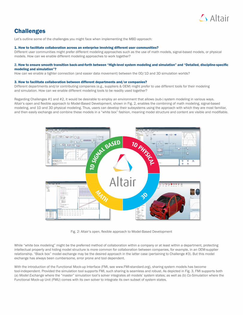
Regarding Challenges #1 and #2, it would be desirable to employ an environment that allows (sub-) system modeling in various ways. Altair’s open and flexible approach to Model-Based Development, shown in Fig. 2, enables the combining of math modeling, signal-based modeling, and 1D and 3D physical modeling. Thus, users can develop their subsystems using the approach with which they are most familiar, and then easily exchange and combine these models in a “white box” fashion, meaning model structure and content are visible and modifiable.
While “white box modeling” might be the preferred method of collaboration within a company or at least within a department, protecting intellectual property and hiding model structure is more common for collaboration between companies, for example, in an OEM-supplier relationship. “Black box” model exchange may be the desired approach in the latter case (pertaining to Challenge #3). But this model exchange has always been cumbersome, error prone and tool dependent.
With the introduction of the Functional Mock-up Interface (FMI, see www.FMI-standard.org), sharing system models has become tool-independent. Provided the simulation tool supports FMI, such sharing is seamless and robust. As depicted in Fig. 3, FMI supports both (a) Model Exchange where the “master” simulation tool’s solver integrates all models’ system states; as well as (b) Co-Simulation where the Functional Mock-up Unit (FMU) comes with its own solver to integrate its own subset of system states.
Fig. 2: Altair’s open, flexible approach to Model-Based Development

Addressing the ChallengesIn the Early Concept design stage (towards the top of the V-diagram), product developers strive to find the optimal physical realization of the various system functions, based on the functional requirements defined for the system. Simulation models supporting this stage are char-acterized by a high degree of abstraction thus lower fidelity (since the available data is limited at this stage). The ability to provide directional qualitative insight into the system performance depends on shorter simulation times, thus allowing for the exploration of numerous design variants. Depending on the user’s preference, these models are described in terms of mathematical equations, signal flow diagrams and/or physical diagrams, and are often called 0D or 1D simulation models (see the left side of Fig. 4).
In the Detailed design stage (towards the bottom of the V-diagram), discipline-specific models are employed for subsystem optimization. They are characterized by a lower degree of abstraction and a large amount of detailed information (geometry and other data). The ability to provide higher-fidelity quantitative insight into the discipline-specific system performance requires longer simulation times, thus limiting the exploration of design variants. Since these models are mostly derived from the geometrical definition of the system components, these models are called 3D simulation models (see the right side of Fig. 4).
Transitioning seamlessly from Concept design to Detailed design isn’t straightforward, due to the different modeling paradigms (abstraction vs. detail, qualitative vs. quantitative, …). It would be valuable to start with the functional structure (i.e., bill of material) of the system, then to employ a simulation environment that provides different degrees of model fidelity depending on the available data and the simulation task at hand. The next example describes first attempts in this direction.
Fig. 3: Combining subsystem models using FMI through (a) Model Exchange or (b) Co-Simulation
Hybrid Modeling Approaches
Lower Model Fidelity (More Abstraction)Shorter Simulation Time
Higher Model Fidelity (Less Abstraction)Longer Simulation Time
All0D/1D
All3D1D 3D
Fig. 4: Altair’s flexible MBD platform allows the complete spectrum of hybrid modeling approaches

Getting the best out of 1D and 3D modelsLet’s illustrate an ideal Model-Based Development process by using the example of an automotive vehicle HVAC system. The simulation model may be constructed as shown in Fig. 5 with the man-machine interface on the top level, and on the lower levels the HVAC system (composed of blower, evaporator, heater, and controller subsystems) and a model of the cabin (composed of one module for calculating the thermal loads plus another module for the water vapor loads).
To support the Concept design stage, one can create lumped parameter 1D models for the different modules and combine them in a simulation environment as shown on the left of Fig. 6. The plots show results from a typical simulation of the overall system performance: cooling down the vehicle cabin to the desired temperature of 24oC and reducing the humidity to a comfortable level.
Fig. 5: Simulation model tree for an automotive vehicle HVAC system
Fig. 6: HVAC example of combining 0D/1D and 3D models and simulations
Altair Engineering, Inc., World Headquarters: 1820 E. Big Beaver Rd., Troy, MI 48083-2031 USAPhone: +1.248.614.2400 • Fax: +1.248.614.2411 • www.altair.com • [email protected]
As explained previously, these models require only a limited set of inputs, run fast, and enable investigating numerous design variants. One can use them to optimize the overall system, design the control algorithms, and test the controls in a hardware-in-the-loop environment.
As shown in the right side of Fig. 6, the connection to the 3D world can be made in various fashions. For instance, CFD models of the various subsystems can:
• either be employed in the Detailed design stage for subsystem optimization;• or combined with Design-of-Experiment (DOE) techniques to generate parametric 1D subsystem models used upfront (because they still provide relatively faster solve times yet with more accuracy).
Altair also provides a co-simulation environment where, for example, the 1D models/simulations for the cabin are replaced by a 3D CFD model/simulation using AcuSolve. So the question is no longer whether to choose 1D or 3D simulation – we are now able to combine the best from the two worlds moving more seamlessly from abstraction (lower fidelity) to detail (higher fidelity) and from qualitative to quantitative predictions. Referring again to Fig. 4, this is like having a slider which we can move continuously anywhere from left to right along the spectrum, rather than being limited to only the extremes or to other pre-defined discrete combinations.
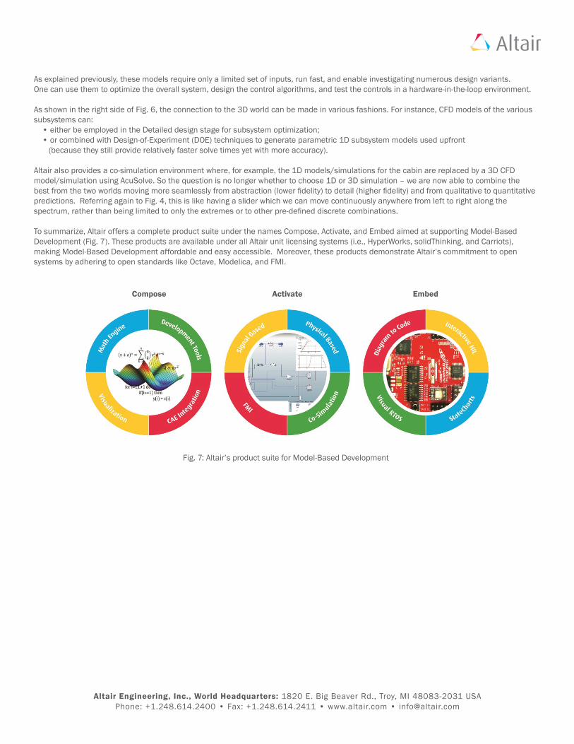
To summarize, Altair offers a complete product suite under the names Compose, Activate, and Embed aimed at supporting Model-Based Development (Fig. 7). These products are available under all Altair unit licensing systems (i.e., HyperWorks, solidThinking, and Carriots), making Model-Based Development affordable and easy accessible. Moreover, these products demonstrate Altair’s commitment to open systems by adhering to open standards like Octave, Modelica, and FMI.
Fig. 7: Altair’s product suite for Model-Based Development
Compose Activate Embed