model a simple conveyor
TRANSCRIPT

© 2017 Visual Components Oy | PAGE 1 OF 18 |
VISUAL COMPONENTS [ MODELING ]
Model a Simple ConveyorVisual Components 4.0 | Version: March 13, 2017
A conveyor allows you to move components from one location to another. In some cases, you can move components onto other conveyors. In other cases, you can use a sensor to detect moving parts and execute a process. For example, you can use conveyors with robots to load and unload parts.
In this tutorial you learn how to:
▪ Import geometry and create a new component.
▪ Edit and collapse geometry contained in features.
▪ Split, clone and transform geometry using tools and operations.
▪ Create and use component properties to write expressions.
▪ Use a wizard to quickly model a component as a conveyor, including its path and interfaces.
Communitycommunity.visualcomponents.net

| PAGE 2 OF 18 | IMPOrT GEOMETry
Import GeometryYou can import a supported CAD file in the 3D world. Initially, imported geometry is stored in a new component. Depending on the CAD file type, the Import command may or may not provide additional options.
1. Press CTRL+N to clear the 3D world. This is the preferred modeling environment for any new component.
2. On the Home tab, in the Import group, click Geometry, and then open the ConveyorGeometry.3ds file for this tutorial.
3. In the Import model task pane, click Import.
SAVE COMPONENT | PAGE 3 OF 18 |
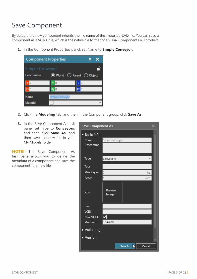
Save ComponentBy default, the new component inherits the file name of the imported CAD file. You can save a component as a VCMX file, which is the native file format of a Visual Components 4.0 product.
1. In the Component Properties panel, set Name to Simple Conveyor.
2. Click the Modeling tab, and then in the Component group, click Save As.
3. In the Save Component As task pane, set Type to Conveyors, and then click Save As, and then save the new file in your My Models folder.
NOTE! The Save Component As task pane allows you to define the metadata of a component and save the component to a new file.
| PAGE 4 OF 18 | SELECT AND EDIT GEOMETry
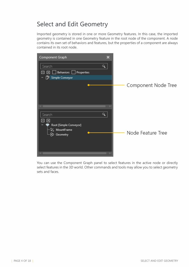
Select and Edit GeometryImported geometry is stored in one or more Geometry features. In this case, the imported geometry is contained in one Geometry feature in the root node of the component. A node contains its own set of behaviors and features, but the properties of a component are always contained in its root node.
You can use the Component Graph panel to select features in the active node or directly select features in the 3D world. Other commands and tools may allow you to select geometry sets and faces.

SELECT AND EDIT GEOMETry | PAGE 5 OF 18 |
1. In the 3D world, click any part of the conveyor to select the feature of its geometry.
The origin of the selected feature is not at the beginning end of the conveyor. You can fix this by repositioning the feature and collapsing it. To determine the offset in XYZ coordinates, take a measurement.
2. On the Modeling tab, in the Tools group, click Measure.
3. In the Measure task pane, under Snap Type, click Origin, and then click the conveyor to select the origin of its root node.
4. In the Measure task pane, under Snap Type, click Edge, and then click a bottom outer corner point of a leg on the right side of the conveyor.
5. Click an empty space in the 3D world to exit the Measurement command. The results of the measurement are printed in the Output panel.
| PAGE 6 OF 18 | SELECT AND EDIT GEOMETry
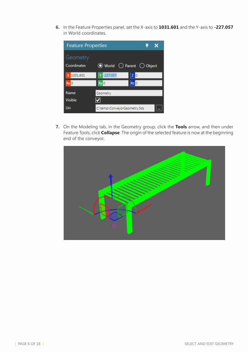
6. In the Feature Properties panel, set the X-axis to 1031.601 and the Y-axis to -227.057 in World coordinates.
7. On the Modeling tab, in the Geometry group, click the Tools arrow, and then under Feature Tools, click Collapse. The origin of the selected feature is now at the beginning end of the conveyor.

SPLIT GEOMETry | PAGE 7 OF 18 |
Split GeometryThe geometry of the conveyor can be split up into different Geometry features. This would allow you to apply operations to specific geometry, for example the roll bars, legs and side rails of the conveyor.
roll Bars
1. On the Modeling tab, in the Geometry group, click the Tools arrow, and then under Feature Tools, click Split.
2. In the Split feature task pane, set Split level to Set.
3. In the 3D world, click the first roll bar at the beginning of the conveyor to select it.
4. In the Split feature task pane, click Split to move the selected roll bar geometry into a new feature.
NOTE! In this case, you only need one roll bar, which you will clone in a later section.
5. In the Feature Properties panel, set Name to RollBars.
| PAGE 8 OF 18 | SPLIT GEOMETry
Side rails
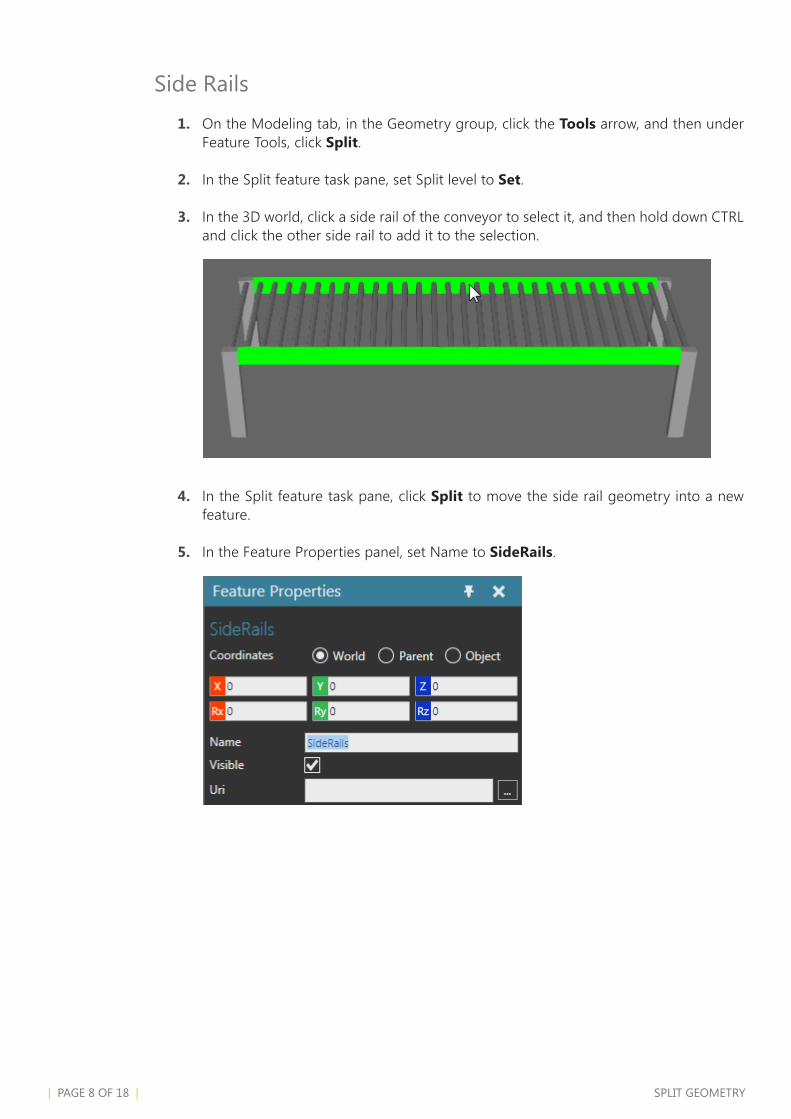
1. On the Modeling tab, in the Geometry group, click the Tools arrow, and then under Feature Tools, click Split.
2. In the Split feature task pane, set Split level to Set.
3. In the 3D world, click a side rail of the conveyor to select it, and then hold down CTRL and click the other side rail to add it to the selection.
4. In the Split feature task pane, click Split to move the side rail geometry into a new feature.
5. In the Feature Properties panel, set Name to SideRails.

SPLIT GEOMETry | PAGE 9 OF 18 |
Legs
1. On the Modeling tab, in the Geometry group, click the Tools arrow, and then under Feature Tools, click Split.
2. In the Split feature task pane, set Split level to Set.
3. In the 3D world, click a leg of the conveyor to select it, and then hold down CTRL and click the other legs to add them to the selection.
4. In the Split feature task pane, click Split to move the leg geometry into a new feature.
5. In the Feature Properties panel, set Name to Legs.
6. In the Component Graph panel, click Geometry feature, and then press DELETE to remove the feature and the geometry of the other roll bars. The node feature tree should now have three separate Geometry features for the conveyor legs, roll bars and side rails.

| PAGE 10 OF 18 | CLONE GEOMETry
Clone GeometryA feature and its geometry can be cloned using a feature operation. A feature operation affects its subfeatures, features that are nested in the tree of the operation feature. Generally, cloned features share geometry to reduce the data count of a component.
In some cases, you may want to use a component property to control the number of times a feature is cloned.
1. On the Modeling tab, in the Properties group, click the Properties arrow, and then under Basic, click Real. This adds a component property whose value is a real number.
2. In the Property task pane, set Name to CLength, Quantity to Distance, Constraints to 1000-10000 and Value to 1000.
A constraint allows you to limit the value of a component property. In some cases, the constraint can be a range of min and max values. In other cases, the constraint can be a list of values known as steps. How you define the constraint depends on its property type and a tooltip for the Constraints field will inform you of the syntax.
CLONE GEOMETry | PAGE 11 OF 18 |
3. On the Modeling tab, in the Geometry group, click the Features arrow, and then under Clone, click Linear Clone.
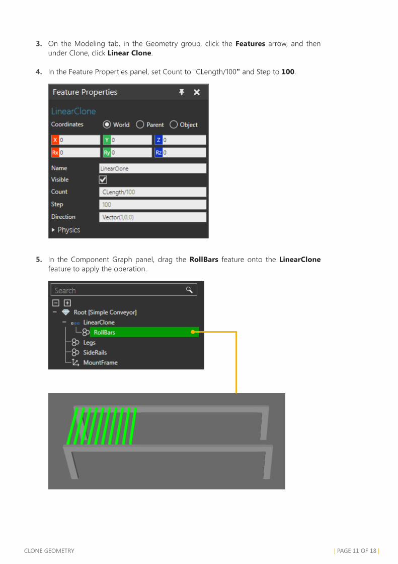
4. In the Feature Properties panel, set Count to "CLength/100" and Step to 100.
5. In the Component Graph panel, drag the RollBars feature onto the LinearClone feature to apply the operation.
| PAGE 12 OF 18 | TrANSFOrM GEOMETry
Transform GeometryA Transform feature allows you to transform other features using an expression. For example, you can translate, rotate and scale geometry.
1. On the Modeling tab, in the Geometry group, click the Features arrow, and then under Transform, click Transform.
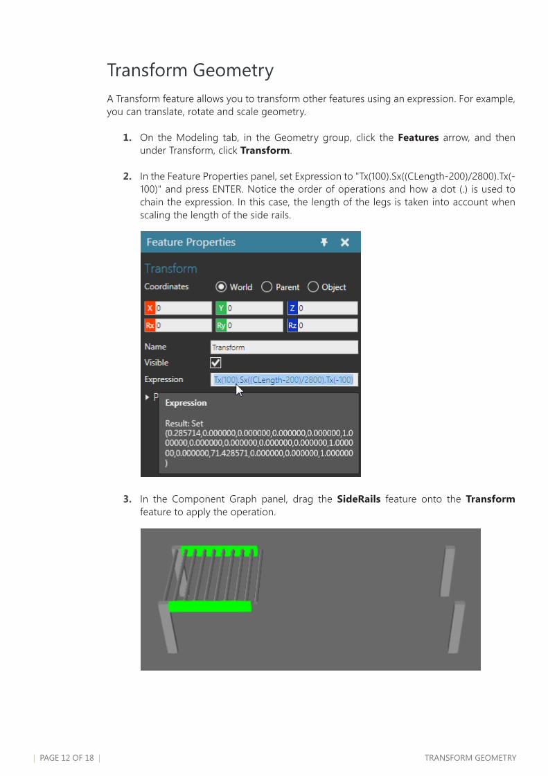
2. In the Feature Properties panel, set Expression to "Tx(100).Sx((CLength-200)/2800).Tx(-100)" and press ENTER. Notice the order of operations and how a dot (.) is used to chain the expression. In this case, the length of the legs is taken into account when scaling the length of the side rails.
3. In the Component Graph panel, drag the SideRails feature onto the Transform feature to apply the operation.

ExErCISE - SPLIT AND CLONE LEGS | PAGE 13 OF 18 |
Exercise - Split and Clone LegsYou now know how to split geometry into different features and apply operations. The back legs of the conveyor can be removed and replaced by cloning the front legs. Try to do this on your own or follow the given steps.
1. Use the Split tool to separate the back legs of the conveyor into a new Geometry feature, and then delete that new feature.
2. Add a Linear Clone feature with a Count of 2 and a Step of "CLength-100" which will create a set of legs at the beginning and end of the conveyor.
3. Drag the Legs feature onto the new Linear Clone feature to apply the operation.
4. Test your work by setting CLength to 3000.

| PAGE 14 OF 18 | CONVEyOr WIzArD
Conveyor WizardA Conveyor wizard can be used to quickly model the path and interfaces of a conveyor.
1. On the Modeling tab, in the Extra group, click the Wizards arrow, and then click Conveyor.
2. In the Conveyor task pane, click Create Conveyor Behaviours, and then click Close.
3. In the Component Graph panel, expand the component node tree. Notice the conveyor now has a path and a set of interfaces for connecting to other components.
CONVEyOr WIzArD | PAGE 15 OF 18 |
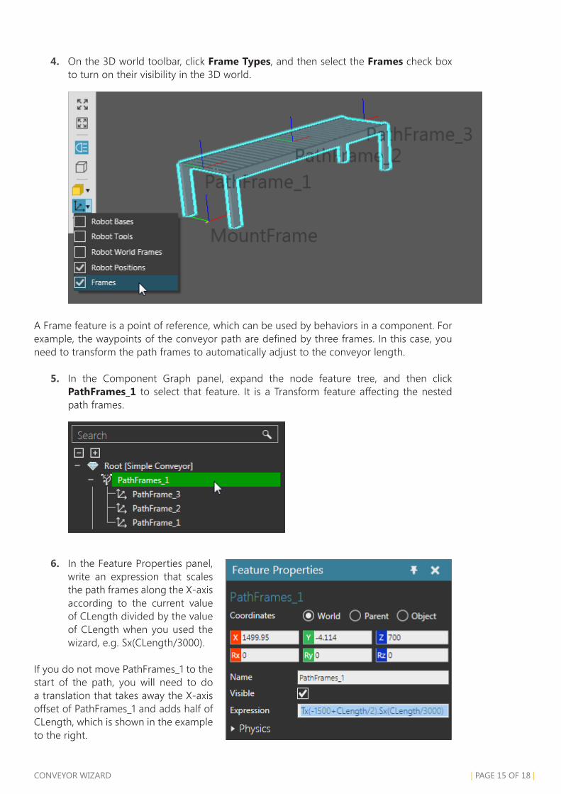
4. On the 3D world toolbar, click Frame Types, and then select the Frames check box to turn on their visibility in the 3D world.
A Frame feature is a point of reference, which can be used by behaviors in a component. For example, the waypoints of the conveyor path are defined by three frames. In this case, you need to transform the path frames to automatically adjust to the conveyor length.
5. In the Component Graph panel, expand the node feature tree, and then click PathFrames_1 to select that feature. It is a Transform feature affecting the nested path frames.
6. In the Feature Properties panel, write an expression that scales the path frames along the X-axis according to the current value of CLength divided by the value of CLength when you used the wizard, e.g. Sx(CLength/3000).
If you do not move PathFrames_1 to the start of the path, you will need to do a translation that takes away the X-axis offset of PathFrames_1 and adds half of CLength, which is shown in the example to the right.

| PAGE 16 OF 18 | TEST AND SAVE
Test and SaveYou can now test the conveyor by connecting it to other components.
1. Save the component.
2. Click the Home tab, and then in the eCatalog panel, Collections view, under Models by Type, click Feeders, and then add and connect a Shape Feeder to the beginning end of the conveyor in the 3D world.
3. In the Component Properties panel, Default tab, set Product to CollarPallet.
4. In the eCatalog panel, Collections view, under Models by Type, expand Conveyors, click Visual Components, and then add and connect a Conveyor to the other end of the conveyor in the 3D world.
5. In the Component Properties panel, Default tab, set ConveyorWidth to 800.

TEST AND SAVE | PAGE 17 OF 18 |
6. Run the simulation, verify pallets move from one conveyor to another, and then reset the simulation.
7. In the eCatalog panel, Collections view, under Models by Type, click Processors, and then add and connect a Conveyor Sensor to your modeled conveyor. The sensor should attach itself to the conveyor path.
8. Save the layout.

| PAGE 18 OF 18 | rEVIEW
reviewIn this tutorial you learned how to model a simple conveyor. You know how to import and split up geometry into different features. You know how to create component properties and use them with operation features. For example, you know how to clone and transform geometry. You also know how to use a Conveyor wizard to quickly create a path and interfaces for moving parts from one component to another during a simulation. It might be helpful to practice these new skills by completing a parametric conveyor tutorial or start learning how to model a turn unit.