model 6511rc matrix switch - patton electronics€¢ the matrix switch will connect to an sdh/stm-1...
TRANSCRIPT

Model 6511RC
Matrix Switch
Getting Started Guide
Sales Office:
+1 (301) 975-1000
Technical Support:
+1 (301) 975-1007
E-mail:
WWW:
www.patton.com
Document Number:
11501U1-001 Rev. A
Part Number:
07MD6511RC-GS
Revised:
September 30, 2004

Patton Electronics Company, Inc.
7622 Rickenbacker DriveGaithersburg, MD 20879 USA
tel: +1 (301) 975-1000fax: +1 (301) 869-9293
support: +1 (301) 975-1007url: www.patton.com
e-mail: [email protected]
Copyright © 2004, Patton Electronics Company. All rights reserved.
The information in this document is subject to change without notice. Patton Electronics assumes no liability for errors that may appear in this document.
The software described in this document is furnished under a license and may be used or copied only in accordance with the terms of such license.

Contents
Contents ......................................................................................................................................................... 3Compliance Information ................................................................................................................................ 7
Radio and TV Interference ...............................................................................................................................7Industry Canada Notice ....................................................................................................................................7FCC Part 68 (ACTA) Statement .......................................................................................................................7CE Notice .........................................................................................................................................................8
About this guide ............................................................................................................................................. 9Audience................................................................................................................................................................. 9Structure................................................................................................................................................................. 9Precautions ........................................................................................................................................................... 10Typographical conventions used in this document................................................................................................ 10
General conventions .......................................................................................................................................10Mouse conventions .........................................................................................................................................11
1 Introduction.................................................................................................................................................. 13Model 6511RC Matrix Switch overview................................................................................................................14Hardware overview ................................................................................................................................................16
ForeFront chassis architectures ........................................................................................................................19ForeFront Model 6476 6U cPCI chassis ...................................................................................................19The ForeFront Model 6676 9U chassis .....................................................................................................20
Matrix Switch functionality ............................................................................................................................21TDM mapping and aggregation ................................................................................................................21TDM bus architecture ...............................................................................................................................22STM-1 link architecture ............................................................................................................................22Matrix Switch TDM capacity ....................................................................................................................23
Matrix Switch Ethernet Switching ..................................................................................................................23Management ...................................................................................................................................................24
Management Services ................................................................................................................................24Management Interfaces .............................................................................................................................24Management Approach .............................................................................................................................24
Matrix Switch Interfaces .................................................................................................................................25WAN Interfaces ........................................................................................................................................25Mid-Plane Interfaces .................................................................................................................................25LAN Interface ...........................................................................................................................................25RS-232 Config port ..................................................................................................................................26
Power system ..................................................................................................................................................26Central processing unit ...................................................................................................................................26System timing .................................................................................................................................................26
Clocking Mode .........................................................................................................................................26Clocking Source ........................................................................................................................................26
3
Contents
Model 6511RC Getting Started Guide
Temperature ...................................................................................................................................................27Altitude ...........................................................................................................................................................27Humidity ........................................................................................................................................................27Physical dimensions ........................................................................................................................................27LED Indicators ...............................................................................................................................................27
Approvals ..............................................................................................................................................................29
2 Hardware installation.................................................................................................................................... 31Introduction ..........................................................................................................................................................32Unpacking the Model 6511RC Matrix Switch ......................................................................................................32Verifying that the ForeFront chassis is properly installed .......................................................................................32
Verfying correct electrical grounding ...............................................................................................................33Verifying correct cover plate installation .........................................................................................................33
Matrix Switch hardware installation ......................................................................................................................34Installing the network cables..................................................................................................................................35
Connecting the front-panel Ethernet LAN port ..............................................................................................36Connecting the 10/100Base-T Ethernet port to an Ethernet switch or hub ...............................................36Connecting the 10/100Base-T Ethernet port to an Ethernet-capable workstation or PC ...........................36
Connecting the front-panel EIA-561 RS-232 configuration port (DCE configured) .......................................37Connecting the rear-panel STM-1 WAN port to an SDH network ................................................................37
Connecting the STM-1 optical interface to fiber-optic network cables ......................................................37Connecting the STM-1 electrical interface to coaxial network cables .........................................................38
Connecting the rear-panel Ethernet WAN/management ports ........................................................................39Connecting the 10/100/1000 Base-T Ethernet ports to a router, hub or switch ........................................40
Completing the hardware installation ....................................................................................................................40
3 Configuring the Matrix Switch for operation................................................................................................ 41Introduction ..........................................................................................................................................................42Configuration prerequisites ...................................................................................................................................42Initial configuration through the RS-232 control port ...........................................................................................43
Connecting the DB9-RJ45 adapter with the included cable ............................................................................43Setting up the HyperTerminal (or similar program) session ............................................................................44
Using a browser to complete Model 6511RC configuration ..................................................................................47Displaying the Matrix Switch 6511RC web administration pages ...................................................................47
Home page overview .................................................................................................................................49Configuring the default gateway .....................................................................................................................51Configuring the system clocking parameters ...................................................................................................52
Module clocking mode ..............................................................................................................................52Module clocking source and fallback .........................................................................................................53
Example 1 ...........................................................................................................................................53Example 2 ...........................................................................................................................................54
Configuring the SDH circuit parameters ........................................................................................................54Accessing the SDH circuit parameters .......................................................................................................55Configuring the SDH physical interface type ............................................................................................56Configuring the SDH interface parameters ...............................................................................................56
4
Model 6511RC Getting Started Guide
Contents
Configuring the SDH path trace parameters .............................................................................................57Configuring DS0 idle codes ............................................................................................................................58
Accessing the idle code configuration ........................................................................................................59Defining the DS0 idle code configuration .................................................................................................60
Selecting the SDH mapping path ....................................................................................................................60Defining DS0 mappings .................................................................................................................................62
Defining DS0 mappings using E1 port format ..........................................................................................64Examples for configuring DS0 mappings. .................................................................................................65Defining DS0 mappings using TU format ................................................................................................69Examples for configuring DS0 mappings. .................................................................................................72
Saving your configuration ...............................................................................................................................74Backing up your configuration parameters.............................................................................................................75
Backing up the configuration store in flash memory .......................................................................................76Completing the installation ...................................................................................................................................77
4 Operation and shutdown .............................................................................................................................. 79Introduction ..........................................................................................................................................................80Activating the Model 6511RC...............................................................................................................................80De-activating the Model 6511RC..........................................................................................................................80
5 Troubleshooting and maintenance................................................................................................................ 81Introduction ..........................................................................................................................................................82Troubleshooting during initial deployment ...........................................................................................................82General fault analysis .............................................................................................................................................83Matrix Switch test tools .........................................................................................................................................86
Loopback test modes for the STM-1 port .......................................................................................................86Facility Loop [sonetFacilityLoop(1)] .........................................................................................................87Terminal loop [sonetTerminalLoop(2)] ....................................................................................................88Other Loop [sonetOtherLoop(3)] .............................................................................................................90
SDH section trace and path trace ....................................................................................................................90Sections and paths .....................................................................................................................................91Section trace ..............................................................................................................................................91Path trace ..................................................................................................................................................92Number of paths per frame .......................................................................................................................93
Periodic maintenance ............................................................................................................................................94Calibration ......................................................................................................................................................94
Maintenance..........................................................................................................................................................94Replacing the Model 6511RC .........................................................................................................................94
Exporting the current Model 6511RC configuration ................................................................................94Removing the defective Model 6511RC ....................................................................................................97Installing the replacement Model 6511RC ................................................................................................98Importing a saved configuration ................................................................................................................98Completing the installation .......................................................................................................................99
6 Contacting Patton for assistance ................................................................................................................. 101Introduction ........................................................................................................................................................102
5

Contents
Model 6511RC Getting Started Guide
Contact information............................................................................................................................................102Warranty Service and Returned Merchandise Authorizations (RMAs).................................................................102
Warranty coverage ........................................................................................................................................102Out-of-warranty service ...........................................................................................................................102Returns for credit ....................................................................................................................................102Return for credit policy ...........................................................................................................................103
RMA numbers ..............................................................................................................................................103Shipping instructions ..............................................................................................................................103
6
Compliance Information
Radio and TV InterferenceThe Model 6511RC generates and uses radio frequency energy, and if not installed and used properly—that is, in strict accordance with the manufacturer's instructions—may cause interference to radio and television reception. The Model 6511RC has been tested and found to comply with the limits for a Class A computing device in accordance with the specifications in Subpart B of Part 15 of FCC rules, which are designed to pro-vide reasonable protection from such interference in a commercial installation. However, there is no guarantee that interference will not occur in a particular installation. If the Model 6511RC causes interference to radio or television reception, which can be determined by disconnecting the cables, try to correct the interference by one or more of the following measures: moving the computing equipment away from the receiver, re-orienting the receiving antenna, and/or plugging the receiving equipment into a different AC outlet (such that the com-puting equipment and receiver are on different branches).
Industry Canada Notice
Note This equipment meets the applicable Industry Canada Terminal Equipment Technical Specifications. This is confirmed by the regis-tration number. The abbreviation, IC, before the registration number signifies that registration was performed based on a Declaration of conformity indicating that Industry Canada technical specifications were met. It does not imply that Industry Canada approved the equipment.
FCC Part 68 (ACTA) StatementThis equipment complies with Part 68 of FCC rules and the requirements adopted by ACTA. On the bottom side of this equipment is a label that contains—among other information—a product identifier in the format US: AAAEQ##TXXXX. If requested, this number must be provided to the telephone company.
A plug and jack used to connect this equipment to the premises wiring and telephone network must comply with the applicable FCC Part 68 rules and requirements adopted by the ACTA.
This equipment uses a Universal Service Order Code (USOC) jack: RJ-11C.
If this equipment causes harm to the telephone network, the telephone company will notify you in advance that temporary discontinuance of service may be required. But if advance notice isn’t practical, the telephone company will notify the customer as soon as possible. Also, you will be advised of your right to file a complaint with the FCC if you believe it is necessary.
The telephone company may make changes in its facilities, equipment, operations or procedures that could affect the operation of the equipment. If this happens the telephone company will provide advance notice in order for you to make necessary modifications to maintain uninterrupted service.
Users should not attempt to establish or modify ground connections themselves, instead they should contact the appropriate electric inspection authority or electrician.
7
Compliance Information
Model 6511RC Getting Started Guide
If trouble is experienced with this equipment, for repair or warranty information, please contact our company. If the equipment is causing harm to the telephone network, the telephone company may request that you dis-connect the equipment until the problem is resolved.
Connection to party line service is subject to state tariffs. Contact the state public utility commission, public service commission or corporation commission for information.
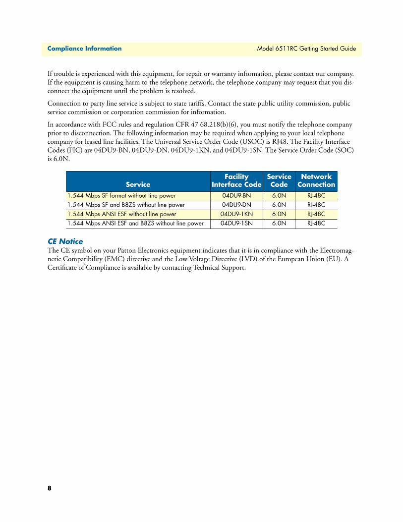
In accordance with FCC rules and regulation CFR 47 68.218(b)(6), you must notify the telephone company prior to disconnection. The following information may be required when applying to your local telephone company for leased line facilities. The Universal Service Order Code (USOC) is RJ48. The Facility Interface Codes (FIC) are 04DU9-BN, 04DU9-DN, 04DU9-1KN, and 04DU9-1SN. The Service Order Code (SOC) is 6.0N.
CE NoticeThe CE symbol on your Patton Electronics equipment indicates that it is in compliance with the Electromag-netic Compatibility (EMC) directive and the Low Voltage Directive (LVD) of the European Union (EU). A Certificate of Compliance is available by contacting Technical Support.
ServiceFacility
Interface CodeService Code
Network Connection
1.544 Mbps SF format without line power 04DU9-BN 6.0N RJ-48C1.544 Mbps SF and B8ZS without line power 04DU9-DN 6.0N RJ-48C1.544 Mbps ANSI ESF without line power 04DU9-1KN 6.0N RJ-48C1.544 Mbps ANSI ESF and B8ZS without line power 04DU9-1SN 6.0N RJ-48C
8

About this guideThis guide describes installing and configuring a Patton Electronics Model 6511 TDM-Digital Access Concen-trator (Matrix Switch). By the time you are finished with this guide, your Matrix Switch will be connected to the remote DSL modems and transferring data. The instructions in this guide are based on the following assumptions:
• The Matrix Switch is installed in a Patton ForeFront chassis
• The Matrix Switch will connect to an SDH/STM-1 network
• There is a LAN connected to one of the Matrix Switch’s Ethernet ports
AudienceThis guide is intended for the following users:
• Operators
• Installers
• Maintenance technicians
StructureThis guide contains the following chapters and appendices:
• Chapter 1 describes the Matrix Switch
• Chapter 2 describes installing the Matrix Switch hardware
• Chapter 3 describes configuring the Matrix Switch for use
• Chapter 4 details how to power up and deactivate the Matrix Switch
• Chapter 5 contains troubleshooting and maintenance information
• Chapter 6 contains information on contacting Patton technical support for assistance
For best results, read the contents of this guide before you install the Matrix Switch.
9

About this guide
Model 6511RC Getting Started Guide
PrecautionsNotes and cautions, which have the following meanings, are used throughout this guide to help you become aware of potential Matrix Switch problems. Warnings relate to personal injury issues, and Cautions refer to potential property damage.
Note Calls attention to important information.
Typographical conventions used in this documentThis section describes the typographical conventions and terms used in this guide.
General conventionsThe procedures described in this manual use the following text conventions:
The shock hazard symbol and WARNING heading indicate a potential electric shock hazard. Strictly follow the warning instructions to avoid injury caused by electric shock.
The alert symbol and WARNING heading indicate a potential safety hazard. Strictly follow the warning instructions to avoid personal injury.
The shock hazard symbol and CAUTION heading indicate a potential electric shock hazard. Strictly follow the instructions to avoid property damage caused by electric shock.
The alert symbol and CAUTION heading indicate a potential haz-ard. Strictly follow the instructions to avoid property damage.
Table 1. General conventions
Convention Meaning
Garamond blue type Indicates a cross-reference hyperlink that points to a figure, graphic, table, or section heading. Clicking on the hyperlink jumps you to the ref-erence. When you have finished reviewing the reference, click on the Go to Previous View button in the Adobe® Acrobat® Reader toolbar to return to your starting point.
Futura bold type Indicates the names of menu bar options.Italicized Futura type Indicates the names of options on pull-down menus.
Futura type Indicates the names of fields or windows.
Garamond bold type Indicates the names of command buttons that execute an action.
< > Angle brackets indicate function and keyboard keys, such as <SHIFT>, <CTRL>, <C>, and so on.
10

Model 6511RC Getting Started Guide
About this guide
Mouse conventionsThe following conventions are used when describing mouse actions:
Are you ready? All system messages and prompts appear in the Courier font as the system would display them.
% dir *.* Bold Courier font indicates where the operator must type a response or command
Table 2. Mouse conventions
Convention Meaning
Left mouse button This button refers to the primary or leftmost mouse button (unless you have changed the default configuration).
Right mouse button This button refers the secondary or rightmost mouse button (unless you have changed the default configuration).
Point This word means to move the mouse in such a way that the tip of the pointing arrow on the screen ends up resting at the desired location.
Click Means to quickly press and release the left or right mouse button (as instructed in the procedure). Make sure you do not move the mouse pointer while clicking a mouse button.
Double-click Means to press and release the same mouse button two times quicklyDrag This word means to point the arrow and then hold down the left or right mouse but-
ton (as instructed in the procedure) as you move the mouse to a new location. When you have moved the mouse pointer to the desired location, you can release the mouse button.
Table 1. General conventions (Continued)
Convention Meaning
11

About this guide
Model 6511RC Getting Started Guide
12

Chapter 1 Introduction
Chapter contentsModel 6511RC Matrix Switch overview................................................................................................................14Hardware overview ................................................................................................................................................16
ForeFront chassis architectures ........................................................................................................................19ForeFront Model 6476 6U cPCI chassis ...................................................................................................19The ForeFront Model 6676 9U chassis .....................................................................................................20
Matrix Switch functionality ............................................................................................................................21TDM mapping and aggregation ................................................................................................................21TDM bus architecture ...............................................................................................................................22STM-1 link architecture ............................................................................................................................22Matrix Switch TDM capacity ....................................................................................................................23
Matrix Switch Ethernet Switching ..................................................................................................................23Management ...................................................................................................................................................24
Management Services ................................................................................................................................24Management Interfaces .............................................................................................................................24Management Approach .............................................................................................................................24
Matrix Switch Interfaces .................................................................................................................................25WAN Interfaces ........................................................................................................................................25Mid-Plane Interfaces .................................................................................................................................25LAN Interface ...........................................................................................................................................25RS-232 Config port ..................................................................................................................................26
Power system ..................................................................................................................................................26Central processing unit ...................................................................................................................................26System timing .................................................................................................................................................26
Clocking Mode .........................................................................................................................................26
Clocking Source ........................................................................................................................................26Temperature ...................................................................................................................................................27Altitude ...........................................................................................................................................................27Humidity ........................................................................................................................................................27Physical dimensions ........................................................................................................................................27LED Indicators ...............................................................................................................................................27
Approvals ..............................................................................................................................................................29
13

1 • Introduction
Model 6511RC Getting Started Guide
Model 6511RC Matrix Switch overviewThe Model 6511RC Matrix Switch (see figure 1) combines TDM aggregation and cross-connection with high-speed packet switching over synchronous digital hierarchy (SDH) and Ethernet uplinks for the Patton Fore-Front Access Infrastructure Solutions (AIS) system. The web-manageable Matrix Switch provides a fully non-blocking mapping and switching matrix for TDM and Ethernet traffic traversing the ForeFront chassis or chas-sis segment. With the Model 6511RC, ForeFront AIS can deliver aggregated TDM and IP traffic on high-speed SDH and Ethernet trunks. The Matrix Switch is designed for installation and operation in either the ForeFront Xtreme Model 6676 cPCI 9U chassis or the ForeFront FullPipe Model 6476 6U chassis. Each model 6511RC Matrix Switch includes an on-board TDM multiplexer, a powerful Ethernet switch, a 155 Mbps SDH/STM-1 trunk port, and two 10/100/1000 Mbps Ethernet interfaces for high-speed packet-switched uplinks.
Figure 1. Model 6511RC Matrix Switch front blade
14 Model 6511RC Matrix Switch overview

Model 6511RC Getting Started Guide
1 • Introduction
Figure 2 shows the major functions and connections the Matrix Switch provides within the ForeFront chassis. Each Model 6511RC enables service providers to perform SDH multiplexing and demultiplexing with any-to-any timeslot mapping for up to 2048 DS0 channels. The on-board TDM multiplexer can map any of the 4096 DS0 timeslots on the TDM bus in the chassis midplane to any of the 2048 DS0s on the STM-1 uplink. Each DS0 consists of a 64 kbps communication channel, or timeslot. The integrated SDH aggregator combines DS0 channels into E1 signal streams, then maps those E1s into a STM-1 signal for high-speed transmission on the SDH trunk.
Figure 2. Model 6511RC Matrix Switch major functions and interfaces
The Model 6511RC provides an Ethernet-switching fabric for packet-based management and user traffic tra-versing the ForeFront chassis. The powerful Ethernet switch connects the high-speed packet-switched bus in the ForeFront chassis midplane with two 10/100/1000 Ethernet uplinks. Offering fast Ethernet switching and flexible timeslot aggregation, the Model 6511RC Matrix Switch enables the ForeFront AIS system to deliver a surprisingly compact, high-speed trunking solution at very low cost.
Model 6511RC Matrix Switch overview 15

1 • Introduction
Model 6511RC Getting Started Guide
Hardware overviewThe Model 6511RC combines DS0 cross-connection and concentration with powerful Ethernet switching in a single-slot blade for installation in a standard CPCI chassis. The Matrix Switch card-set comprises two mod-ules, a processor blade (see figure 1 on page 14) inserted from the front of the ForeFront chassis, and a rear interface blade (see figure 3) inserted opposite to the processor blade. The front and rear blades mate at the mid-plane, which provides the communication path between front and rear blades (see figure 4).
Figure 3. Model 6511RCT rear blade
Figure 4. Model 6511RC Matrix Switch front and rear blade installation
Midplane
Rear Blade
Front Rear
Side view
Front Blade
16 Hardware overview

Model 6511RC Getting Started Guide
1 • Introduction
Figure 5. Model 6511RC front panel LEDs and ports
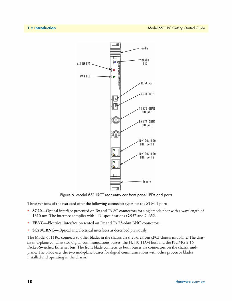
The front panel of the processor blade presents LED status indicators, an RS-232 configuration port and a 10/100 Ethernet management port (see figure 5). The rear entry interface blade (see figure 6 on page 18) pre-sents LEDs indicating alarm and WAN status, physical connectors for the STM-1 port, as well as two 10/100/1000 Ethernet RJ-45 connectors with embedded link and activity status indicator LEDs.
Hardware overview 17
1 • Introduction
Model 6511RC Getting Started Guide
Figure 6. Model 6511RCT rear entry car front panel LEDs and ports
Three versions of the rear card offer the following connector types for the STM-1 port:
• SC20—Optical interface presented on Rx and Tx SC connectors for singlemode fiber with a wavelength of 1310 nm. The interface complies with ITU specifications G.957 and G.652.
• EBNC—Electrical interface presented on Rx and Tx 75-ohm BNC connectors.
• SC20/EBNC—Optical and electrical interfaces as described previously.
The Model 6511RC connects to other blades in the chassis via the ForeFront cPCI chassis midplane. The chas-sis mid-plane contains two digital communications busses, the H.110 TDM bus, and the PICMG 2.16 Packet-Switched Ethernet bus. The front blade connects to both busses via connectors on the chassis mid-plane. The blade uses the two mid-plane busses for digital communications with other processor blades installed and operating in the chassis.
18 Hardware overview

Model 6511RC Getting Started Guide 1 • Introduction
ForeFront chassis architecturesThe Model 6511RC can be installed in the following ForeFront cPCI chassis:
• Model 6476 6U chassis
• Model 6676 9U chassis
ForeFront Model 6476 6U cPCI chassisThe ForeFront Model 6476 6U cPCI chassis provides 8 slots for installing cPCI processor blades (see figure 7). The Model 6476 chassis accepts up to two Model 6511RC blades, installed in the fabric slots (designated by a yellow blade guide). Using the H.110 TDM and PICMG 2.16 packet busses residing in the chassis mid-plane, an installed Model 6511 can communicate with the other blades installed and operating in the remaining slots.
Figure 7. Model 6476 chassis, front view
Hardware overview 19

1 • Introduction Model 6511RC Getting Started Guide
Figure 8. Model 6676 chassis, front view
The ForeFront Model 6676 9U chassisThe ForeFront Model 6676 9U chassis offers 17 slots for installing cPCI processor blades (see figure 8). The Model 6676 midplane is divided into segment R (slots 1 through 8) and segment L (slots 9 through 17). Each mid-plane segment contains its own H.110 and PICMG 2.16 bus, so since each 6511RC connects to one mid-plane segment, two Matrix Switch blades, installed in each of the two segments, are required to serve an entire Model 6676 chassis. The Model 6676 chassis can accept up to four Model 6511RC blades installed in slots called fabric slots (slots 1, 2, 9, and 10) designated by yellow card guides. In each backplane segment, a maxi-mum of two 6511RC blades can be installed for operation to provide switching functions for that segment.
20 Hardware overview

Model 6511RC Getting Started Guide 1 • Introduction
The Model 6511 communicates with the other blades installed and operating in the same segment over the H.110 TDM and PICMG 2.16 packet busses residing in the chassis mid-plane.
Matrix Switch functionalityThe Model 6511 provides the following functionality:
• TDM mapping and aggregation—The Model 6511RC Matrix Switch concentrates the traffic capacity of up to 63 E1 lines for delivery on a 155.54 Mbps optical or electrical STM-1 uplink (see section “TDM mapping and aggregation” for details)
• TDM bus architecture—The Matrix Switch provides an interface to the H.110 bus within the ForeFront chassis.The total capacity of the H.110 bus is 4096 half-duplex DS0 channels, the equivalent of 64 E1 lines (see section “TDM bus architecture” for details)
• STM-1 link architecture—The 155.52 Mbps STM-1 uplink carries 2016 full-duplex (4032 half-duplex) DS0 channels organized into 63 E1 signal streams. Each E1 stream carries 32 full-duplex DS0 channels (64 half-duplex timeslots). The total capacity of the STM-1 uplink on the Model 6511RC is 2016 full-duplex DS0s, the equivalent of 63 E1 lines (see section “STM-1 link architecture” on page 22 for details)
• Matrix Switch TDM capacity—The Matrix Switch provides the means for you to map any DS0 on the H.110 TDM bus to any DS0 on the STM-1 trunk and vice-versa (see section “Matrix Switch TDM capac-ity” on page 23 for details)
TDM mapping and aggregationThe Model 6511RC Matrix Switch concentrates the traffic capacity of up to 63 E1 lines for delivery on a 155.54 Mbps optical or electrical STM-1 uplink. For E1 traffic aggregation, the Matrix Switch performs mul-tiplexing and demultiplexing for all 63 E1 lines comprising the 155.52 Mbps STM-1 uplink. Each E1 line comprises 32 DS0 timeslots. Each timeslot comprises a 64 kbps communication channel, or DS0. The Model 6511RC delivers a fully non-blocking switching matrix to the ForeFront system, providing any-to-any map-ping between all 4096 half-duplex DS0 timeslots carried in the H.110 bus and all 4032 half-duplex DS0 timeslots in the SDH STM-1 uplink.
Hardware overview 21

1 • Introduction Model 6511RC Getting Started Guide
TDM bus architectureThe Matrix Switch provides an interface to the H.110 bus within the ForeFront chassis.The total capacity of the H.110 bus is 4096 half-duplex DS0 channels, the equivalent of 64 E1 lines (see figure 9). Each DS0 chan-nel can be mapped in either direction, transmitting to the Matrix Switch or receiving from the H.110 bus. The H.110 bus organizes the 4096 half-duplex DS0 channels into 32 H.110 ports. Each of the 32 H.110 ports car-ries 128 half-duplex 64 kbps timeslots (DS0s).
Figure 9. H.110 bus and STM-Link capacity
STM-1 link architectureThe 155.52 Mbps STM-1 uplink carries 2016 full-duplex (4032 half-duplex) DS0 channels organized into 63 E1 signal streams. Each E1 stream carries 32 full-duplex DS0 channels (64 half-duplex timeslots). The total capacity of the STM-1 uplink on the Model 6511RC is 2016 full-duplex DS0s, the equivalent of 63 E1 lines. The following sequence describes the process by which the Matrix Switch maps and multiplexes 63 E1 streams into the architecture of the STM-1 signal stream:
• E1 -to- C-12 -to- VC-12 -to- TU-12 -to- TUG-2 -to- VC-3 -to- AU-3 -to- AUG-1 -to- STM-1
Multiplexing occurs at the following points in the mapping sequence:
- Three TU-12s are multiplexed into one tributary unit group-2 (TUG-2).
- Seven TUG-2s are multiplexed into one TUG-3 or administrative unit-3 (AU-3).
- Three AU-3s or TUG-3s are multiplexed into one administrative unit group-1 (AUG-1).
22 Hardware overview

Model 6511RC Getting Started Guide 1 • Introduction
Figure 10 highlights the multiplexing structure of the STM-1 link by ommitting the intermediate steps in the SDH mapping sequence
Figure 10. E1-to-STM-1 multiplexing structure
Matrix Switch TDM capacityThe Matrix Switch provides the means for you to map any DS0 on the H.110 TDM bus to any DS0 on the STM-1 trunk and vice-versa. The difference in capacity between the H.110 bus and the STM-1 link is 64 half-duplex DS0s, the equivalent of one E1 line. The STM-1 uplink provides sufficient capacity to aggregate 98% of the traffic capacity of the H.110 TDM bus. The Model 6511RC provides the capability to map and aggre-gate traffic on the H.110 bus up to the full capacity of the STM-1 trunk.
Matrix Switch Ethernet SwitchingThe Matrix Switch also delivers Ethernet connectivity and switching for any Ethernet traffic traversing the PICMG 2.16 bus to which the blade is connected. The Model 6511RC provides the Ethernet switching fabric for all other blades connected to the same PICMG 2.16 packet-switching bus within the chassis mid-plane. The built-in Ethernet switch switches Ethernet traffic between the PICMG 2.16 bus, the 10/100 Ethernet LAN port presented on the front panel of the front blade, and the two 10/100/1000 Ethernet WAN uplink ports presented on the 6511RCrear panel of the rear blade. All three Ethernet ports provide access to the SNMP agent and HTTP Web Management services within the 6511RC. In addition, all three Ethernet ports provide access via the Internet Protocol to the other blades on the packet bus, including access to the Web Management services residing within those blades. When combined with an external network management system, the Ethernet switching feature on the 6511RC makes it possible to implement a packet-based network management solution for all system elements connected to the same packet-switched bus in the ForeFront chassis.
Hardware overview 23

1 • Introduction Model 6511RC Getting Started Guide
Management
Management ServicesBy providing a rich set of industry-standard management services accessible by a full menu of physical inter-faces, the Model 6511RC offers an extensive selection of management options. The Matrix Switch provides the following management services:
• HTTP Web-Management Interface accessible via any standard web browser
• SNMP version 1 configuration management (specified in RFC 1157)
• MIB II (specified in RFC 1213)
• Command Line Management Interface (CLI)
• SYSLOG Management Client (specified in RFC 3164)
• Out-of-Band RS-232 configuration port for management and control
• TELNET via Ethernet
• Remote Software Upgrade via FTP/TFTP
Management InterfacesYou can reach the Matrix Switch’s management services via any of the following physical interfaces:
• RS-232 Config Port presented as an RJ-45 connector on the front panel of the front blade
• PICMG 2.16 midplane connector block on the front blade
• 10/100 Ethernet port presented as an RJ-45 connector on the front panel of the front blade.
• Two 10/100/1000 Ethernet ports presented as RJ-45 connectors on the rear panel of the rear blade
Management ApproachManaging the Model 6511RC’s may be approached using one of two schemes, generally referred to as In-band or Out-of-band management. In-band management refers to those schemes in which management informa-tion traverses the same network resources as network user traffic. Out-of-band management refers scenarios in which management information does not traverse the same resources as network user traffic. In other words, out-of-band management involves implementing a secondary, special-purpose, management network dedi-cated to carrying management information about the primary, user network. In-band management is more efficient. However, because management information is susceptible to failures in the user network., it is less reliable. Out-of-band management, while more reliable, is also more costly because it involves more equip-ment.
Management access paths into the Model 6511RC for both In-band and Out-of-band approaches are described below.
• In-band management access paths include:
- The two RJ-45 10/100/1000 Ethernet trunk ports on the rear panel of the rear blade support in-band management for applications where the Ethernet link is used as an aggregated trunk for user traffic as well as a path for management information. An external management workstation communicates with the management services in the Matrix Switch via a routed-protocol connection within the Ethernet link. The management connection terminates at the management service within the Matrix Switch.
24 Hardware overview

Model 6511RC Getting Started Guide 1 • Introduction
- The PICMG 2.16 packet-switched bus (PSB). In order to manage the Matrix Switch in-band via the PICMG 2.16 PSB, an external management workstation connects to the ForeFront chassis via another ForeFront blade with management routing capability, such as the Model 6801RC EdgeRoute Network Access Server or model 3096RC TDM Digital Access Concentrator, operating on the same bus. The external management workstation communicates with the ForeFront system using either a Frame Relay or PPP link within a DS0 or within an Ethernet link. The in-band management link terminates on the mod-ule with management routing capability, which in turn communicates with the management services in the Matrix Switch over the PICMG 2.16 PSB.
• Out-of-band management access paths include:
- The RS-232 config port on the front panel of the front blade
- The RJ-45 10/100 Ethernet LAN port on the front panel of the front blade
- The two RJ-45 10/100/1000 Ethernet LAN ports on the rear panel of the rear blade, in applications where these Ethernet links are dedicated to management traffic.
Matrix Switch Interfaces
WAN InterfacesThe 6511RC provides connections to the following WAN interfaces:
• One SDH STM-1 uplink trunk port at 155.54 Mbps -Physical SC or BNC connectors presented on the rear-blade rear panel
• Two Ethernet trunk ports at up to 1 Gbps-Physical RJ-45 connectors presented on the rear-blade rear panel
The STM-1 WAN uplink port may be connected to an SDH network via the Optical SC ore electrical BNC connectors presented on the rear blade.
Mid-Plane Interfaces• Connection to the H.110 Time-Division Multiplexed bus providing 4096 DS0 channels of 64 kbps each
-Physical and electrical connections via the mid-plane connector block on the rear of the front blade
• Connection to the PICMG 2.16 Packet-Switched Bus (PSB)-Physical and electrical connections via the mid-plane connector block on the rear of the front blade
LAN InterfaceThe 10/100-Mbps Ethernet LAN port is presented on an RJ-45 connector with an auto-sensing/full-duplex 10Base-T or 100Base-T interface. Also included are:
• 100Base-TX half-/full-duplex operation (100 + 100)
• 10Base-T half-/full-duplex operation (10 + 10)
• Auto detection and fallback
• 10/100 Mbps link and status indicators
Hardware overview 25

1 • Introduction Model 6511RC Getting Started Guide
RS-232 Config portThe RS-232 Config port provides access to the CLI management service. You will use the Config port to per-form initial configuration of the Model 6511RC. The RS-232 port supports:
• Asynchronous data rates of 19.2 kbps, 8 data bits, no parity, 1 stop bit.
• An RJ-45 connector with EIA-561 pinouts
• A management interface that supports VT-100 terminals
• Hardware flow control (RTS and CTS)
Power systemThe 6511RC obtains power from the CPCI chassis via PCMG 2.11 47-pin power connectors on the front and rear blade. Total power consumption is a maximum of 43 Watts, provided by modular power supplies installed in the cPCI chassis.
Central processing unitThe 6511RC employs an Intel i960VH RISC processor operating at 100 MHz/100 Mips. The CPU controls the memory, front/back-panel and management interface for DS0 timeslot mapping, Ethernet switching, loopback and management services. System memory provided by:
• 4 MB Flash ROM
• 8 MB EDO DRAM
System timingThe system timing for the Matrix Switch must be configured using the blade’s management services, typically via Web Management.
Clocking ModeWhen configured in Master mode, the Matrix Switch serves as the Master clock source (timing reference) for all other blades on the same H.100 bus within the Model 6476 chassis or Model 6676 chassis segment. When configured in Backup mode, the Matrix Switch serves as an alternate Master clocking source (backup) should the Master clocking source fail. When configured in Slave mode, the Matrix Switch will not provide system timing over the H.100 bus for any other blades.
Clocking SourceRegardless of its clocking mode, the Matrix Switch can derive its own system timing from several sources. You will define two clocking sources for the Matrix Switch, a first-choice (Primary Reference) and an alternate (Fall-back Reference). The Matrix switch will derive its own system timing from the Primary Reference as long as it remains available. Should the Primary Reference become unavailable, the Matrix Switch will switch over to the Fallback reference as the clock source for its own system timing. The following clocking sources can serve as either the Primary Reference or Fallback Reference for the Matrix Switch:
• The internal oscillator (clock) residing on the Matrix Switch front blade
• A network clock recovered from the STM-1 SDH signal stream
• Another blade operating in either Primary or Secondary mode on the same bus.
26 Hardware overview

Model 6511RC Getting Started Guide 1 • Introduction
TemperatureOperating range: 32–104˚F (0–40˚C)
AltitudeMaximum operating altitude: 15,000 feet (4,752 meters)
Humidity5 to 95% relative humidity (RH), non-condensing
Physical dimensions• 1.75 inches (4.44 cm) height, standard 19-inch (48.26 cm) width, 12-inch (30.48 cm) depth
• Weight: 1.55 lbs (0.70 kg)
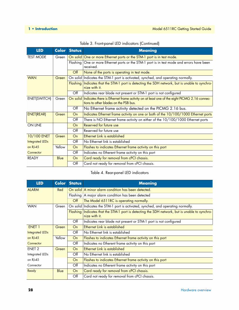
LED IndicatorsLED indicators on the front panel (see figure 5 on page 17) and rear panel (see figure 6 on page 18) display the status of Matrix Switch system resources. The front-panel LEDs are described in table 3. The rear-panel LEDs are described in table 4 on page 28.
Table 3. Front-panel LED indicators
LED Color Status Meaning
POWER Green On solid Power is being applied.Flashing The 6511RC has detected a power failure on a power bus.
Off No input power is being applied.CPU FAIL Red On solid CPU is unable to load the software from FLASH to RAM for operation.
Off The CPU is operating normally.ALARM Yellow On solid A minor alarm condition has been detected.
Flashing A major alarm condition has been detected.Off The Model 6511RC system is operating normally.
SYSTEM Green Flashing The Model 6511RC system is operating normally.Off The Model 6511RCsystem is not functioning properly.
ENET(NODE) Green On solid Indicates there is Ethernet frame activity on one or more of the 6511RC’s Ethernet inter-faces, including the two rear-panel 10/100/1000 ports, the front -panel 10/100 port, and the packet--switched PICMG 2.16 bus.
Off Indicates NO Ethernet frame activity detected on any of the 6511RC’s Ethernet interfaces, including the PICMG 2.16 bus.
CLK SOURCE Green On solid The 6511RC is defined as the Primary (master) clock source for the H.100 busFlashing The 6511RC is defined as the Secondary (alternate master) clock source.
Off The 6511RC is defined as a slave, deriving its clock from the H.110 Bus.CLK ERROR Yellow On solid Primary Master Clock source has been lost and the 6511RC is using the secondary
source for its clock.Flashing Master Clock source and the Secondary Clock source have been lost and the 6511RC
is using its internal crystal for its clock. Off No clock errors currently detected.
Hardware overview 27
1 • Introduction Model 6511RC Getting Started Guide
Table 4. Rear-panel LED indicators
TEST MODE Green On solid One or more Ethernet ports or the STM-1 port is in test mode.Flashing One or more Ethernet ports or the STM-1 port is in test mode and errors have been
received.Off None of the ports is operating in test mode.
WAN Green On solid Indicates the STM-1 port is activated, synched, and operating normally.Flashing Indicates that the STM-1 port is detecting the SDH network, but is unable to synchro-
nize with it.Off Indicates rear blade not present or STM-1 port is not configured
ENET(SWITCH) Green On solid Indicates there is Ethernet frame activity on at least one of the eight PICMG 2.16 connec-tions to other blades on the PSB bus.
Off No Ethernet frame activity detected on the PICMG 2.16 bus.ENET(REAR) Green On Indicates Ethernet frame activity on one or both of the 10/100/1000 Ethernet ports
Off There is NO Ethernet frame activity on either of the 10/100/1000 Ethernet portsON LINE On Reserved for future use
Off Reserved for future use10/100 ENET Green On Ethernet Link is establishedIntegrated LEDs Off No Ethernet link is establishedon RJ-45 Yellow On Flashes to indicates Ethernet frame activity on this portConnector Off Indicates no Etherent frame activity on this portREADY Blue On Card ready for removal from cPCI chassis.
Off Card not ready for removal from cPCI chassis.
LED Color Status Meaning
ALARM Red On solid A minor alarm condition has been detected.Flashing A major alarm condition has been detected
Off The Model 6511RC is operating normally.WAN Green On solid Indicates the STM-1 port is activated, synched, and operating normally.
Flashing Indicates that the STM-1 port is detecting the SDH network, but is unable to synchro-nize with it.
Off Indicates rear blade not present or STM-1 port is not configured ENET 1 Green On Ethernet Link is establishedIntegrated LEDs Off No Ethernet link is establishedon RJ-45 Yellow On Flashes to indicates Ethernet frame activity on this portConnector Off Indicates no Etherent frame activity on this portENET 2 Green On Ethernet Link is establishedIntegrated LEDs Off No Ethernet link is establishedon RJ-45 On Flashes to indicates Ethernet frame activity on this portConnector Off Indicates no Etherent frame activity on this portReady Blue On Card ready for removal from cPCI chassis.
Off Card not ready for removal from cPCI chassis.
Table 3. Front-panel LED indicators (Continued)
LED Color Status Meaning
28 Hardware overview

Model 6511RC Getting Started Guide 1 • Introduction
ApprovalsThe Model 6511RC Matrix Switch has achieved the following approvals and certifications:
• Safety
- UL 60950
- Industry Canada CSA C22.2 No. 60950
• RTTE Directive (CE Mark)
- EMC Directive 89/336/EEC
- Low Voltage Directive 73/23/EEC (EN 60950)
- ETSI CTR 12
- ETSI CTR 13
• EMC
- FCC Part 15, Subpart B, Class A
• Telecom
- FCC Part 68
- Industry Canada CS-03
Approvals 29

1 • Introduction Model 6511RC Getting Started Guide
30 Approvals

Chapter 2 Hardware installation
Chapter contentsIntroduction ..........................................................................................................................................................32Unpacking the Model 6511RC Matrix Switch ......................................................................................................32Verifying that the ForeFront chassis is properly installed .......................................................................................32
Verfying correct electrical grounding ...............................................................................................................33Verifying correct cover plate installation .........................................................................................................33
Matrix Switch hardware installation ......................................................................................................................34Installing the network cables..................................................................................................................................35
Connecting the front-panel Ethernet LAN port ..............................................................................................36Connecting the 10/100Base-T Ethernet port to an Ethernet switch or hub ...............................................36Connecting the 10/100Base-T Ethernet port to an Ethernet-capable workstation or PC ...........................36
Connecting the front-panel EIA-561 RS-232 configuration port (DCE configured) .......................................37Connecting the rear-panel STM-1 WAN port to an SDH network ................................................................37
Connecting the STM-1 optical interface to fiber-optic network cables ......................................................37Connecting the STM-1 electrical interface to coaxial network cables .........................................................38
Connecting the rear-panel Ethernet WAN/management ports ........................................................................39Connecting the 10/100/1000 Base-T Ethernet ports to a router, hub or switch ........................................40
Completing the hardware installation ....................................................................................................................40
31
2 • Hardware installation Model 6511RC Getting Started Guide
IntroductionThis chapter contains the following procedures for installing the Model 6511RC Matrix Switch:
Note Before installing the Matrix Switch, you will need to obtain the line type and encoding of the STM-1 link from your local telephone com-pany (Telco).
• “Unpacking the Model 6511RC Matrix Switch”—lists the contents in the Matrix Switch shipping con-tainer
• “Matrix Switch hardware installation”—describes installing the Matrix Switch on a flat surface or in a stan-dard 19-inch rack
• “Installing the network cables” on page 35—describes installing the power and network interface cables
• “Completing the hardware installation” on page 40—describes testing the Matrix Switch hardware to verify that it is ready for software configuration
Unpacking the Model 6511RC Matrix SwitchInspect the shipping carton for external damage. Note any damage before removing the container contents. Report equipment damage to the shipping carrier immediately for claim purposes. Save all packing materials in case you need to return an item to the factory for servicing.
The Matrix Switch comes with the following items:
• The Model 6511RC Digital Cross-Connect (Matrix Switch)
• One RJ45-to-RJ45 cable for use with the console and Ethernet ports
• A DB9-RJ45 (EIA-561) adapter for connecting a PC's serial port to the Matrix Switch console port
• Model 6511RC Matrix Switch Getting Started Guide
• CD-ROM containing product literature, the Model 6511 G.SHDSL Matrix Switch Getting Started Guide, and the Model 6511 G.SHDSL Matrix Switch Administrator's Reference Guide
Verifying that the ForeFront chassis is properly installedYou must verify that the ForeFront chassis is correctly installed before installing the Matrix Switch hardware into the chassis. Check for the following:
• Correct electrical grounding—Improper chassis grounding may impair proper operation of the STM-1 electrical interface, thereby causing data transmission errors on the STM-1 link. See section “Verfying cor-rect electrical grounding” on page 33 for directions on verify chassis grounding.
• Correctly installed front and rear panels over vacant chassis slots—Absent front or rear panels over vacant module slots leaves the chassis interior open and thereby vulnerable to the following problems:
- Improper EMI shielding against both incoming and outgoing electromagnetic signals
- Impaired operation of the chassis cooling system, resulting in equipment overheating, including the SHD laser subsystem on the Matrix Switch
See section “Verifying correct cover plate installation” on page 33 for directions on verifying proper cover plate installation
32 Introduction

Model 6511RC Getting Started Guide 2 • Hardware installation
Verfying correct electrical groundingDo the following to verify correct electrical grounding:
1. Inspect the rack chassis grounding studs on the AC power module or DC power module (see figure 11 for studs locations) to ensure a #12 AWG ground wire is attached.
Figure 11. AC power module and DC power module grounding studs locations
2. Inspect the remote end the #10 AWG ground wire and verify that it is attached to one of the following grounding sources:
– The building ground rod (generally located at the site’s main service entrance)
– A sprinkler system pipe
– A cold-water pipe
– Building structural steel
Verifying correct cover plate installationMissing front or rear panel cover plates leave the chassis interior open and vulnerable to the following problems:
• Impaired EMI shielding against incoming and outgoing electromagnetic signals
• Reduced chassis cooling system efficiency, which can resulting in equipment overheating, especially in the SHD laser subsystem on the Matrix Switch
Do the following to verify that cover plates are properly installed:
1. Inspect the front of the chassis and verify that a cover plate is installed for each vacant module slot, and verify that each cover plate’s fasteners are tightened securely to the front panel. Missing cover plates must be replaced before installing the Matrix Switch.
Improper chassis grounding may impair the operation of the STM-1 electrical interface, thereby causing data transmission errors on the STM-1 link.
Verifying that the ForeFront chassis is properly installed 33

2 • Hardware installation Model 6511RC Getting Started Guide
Note Missing cover plates can be replaced by calling Patton Sales at +1 (301) 975-1000. The Sales Department is available Monday through Friday, from 8:00 A.M. to 5:00 P.M. EST (8:00 to 17:00 UTC-5).
2. Inspect the rear of the chassis and verify that a cover plate is installed for each vacant module slot, and ver-ify that each cover plate’s fasteners are tightened securely to the rear panel. Missing cover plates must be replaced before installing the Matrix Switch.
Matrix Switch hardware installationDo the following to install the Matrix Switch hardware:
1. Remove the Matrix Switch rear blade from its shipping container.
Note Be sure to wear the anti-static strap to prevent electrostatic damage to the blade.
Note The Matrix Switch should be installed as close as possible to the ter-mination jack provided by the Telco. The location should be well ventilated. Do not block the rack chassis’ cooling vents.
2. Remove the slot cover plate, if present.
3. Unlatch both handles on the Matrix Switch blade by pressing in on the red release button in each handle (see figure 12).
4. While holding the Matrix Switch from the card handles (see figure 12), align the Matrix Switch with the guide rails of the appropriate slot and slide it back until it touches the backplane connectors and the align-ment/ESD pin (see figure 12) engages the chassis. When the blade is fully seated, the red release buttons in the handles click up automatically, thus locking the handles.
Figure 12. Alignment/ESD pin and card handle
5. Tighten the screw fastener located inside each handle to secure the blade to the chassis.
34 Matrix Switch hardware installation

Model 6511RC Getting Started Guide 2 • Hardware installation
6. Insert the front blade into the front chassis slot corresponding to the slot in which you installed the rear blade. Verify that the release buttons in the handles click up to indicate that the board is fully seated and locked into place.
Installing the network cablesThis section describes installing network interface cables on the following front and rear Matrix Switch blade ports:
• The Matrix Switch front blade’s 10/100 Ethernet LAN port and an EIA 561 RS-232 CONFIG port (see figure 13).
• The Matrix Switch rear blade’s STM-1 SDH WAN port (presented in SC optical and 75-ohm BNC electri-cal formats) and two 10/100/100 Ethernet WAN/LAN management ports (see figure 14)
Figure 13. Matrix Switch front blade network interface ports
Figure 14. Matrix Switch rear blade network interface ports
Installing the network cables 35

2 • Hardware installation Model 6511RC Getting Started Guide
Connecting the front-panel Ethernet LAN portThe Matrix Switch includes a 10/100Base-T transceiver, accessible via a physical interface on the front panel of the front blade for connection to an Ethernet LAN. The Ethernet interface complies with IEEE 802.3 and is pre-sented on a 6-pin RJ-45 female receptacle. Once connected to a LAN, the Ethernet port will autosense the speed of the LAN and automatically negotiate half or full-duplex operation. This port provides access to the Matrix Switch’s resident management services, including the HTTP/Web Management feature. This port also connects to the on-board Ethernet Switch, thus providing Ethernet access to other blades within the ForeFront system via the PICMG 2.16 PSB. This section describes connecting the Matrix Switch to the Ethernet LAN via an Ethernet hub, switch, or workstation.
Connecting the 10/100Base-T Ethernet port to an Ethernet switch or hubThe 10/100Base-T Ethernet port (see figure 5) is designed to connect to an Ethernet switch or hub. The Ethernet RJ-45 pin and signal definitions for the Matrix Switch or for a NIC card in a workstation/PC are shown in figure 15. Connect a straight-through CAT-5 cable (one wired as shown in figure 15) between the Matrix Switch and the hub/switch.
Figure 15. Ethernet RJ-45 pin and signal definitions for Matrix Switch
Connecting the 10/100Base-T Ethernet port to an Ethernet-capable workstation or PCThe 10/100Base-T Ethernet port can connect to a single Ethernet-capable workstation or PC by means of a cross-over cable. Refer to figure 16 to assemble a cross-connect cable that will connect between the NIC Ether-net port in the workstation and the Matrix Switch 10/100Base-T Ethernet port.
Figure 16. Cross-over RJ-45-to-RJ-45 Ethernet cable diagram
36 Installing the network cables

Model 6511RC Getting Started Guide 2 • Hardware installation
Connecting the front-panel EIA-561 RS-232 configuration port (DCE configured)Install the supplied RJ-45-to-RJ-45 cable with the DB9-RJ45 adapter between the Matrix Switch RS-232 port (see figure 13 on page 35) and an open serial port on your computer. If you need to assemble your own cable, refer to the pinout diagram in figure 17.
Figure 17. RJ-45 pin and signal definitions for Matrix Switch CONFIG port
Connecting the rear-panel STM-1 WAN port to an SDH networkThe Matrix Switch offers two types of STM-1 interfaces—optical and electrical—presented on the rear panel of the rear blade. Optical interfaces connect to fiber-optic network cables, while the electrical interfaces connect to coaxial network cables. The rear-blade connectors must match the type of network cables and connectors used by the SDH network to which you will connect.
Connecting the STM-1 optical interface to fiber-optic network cablesThe following versions of the Matrix Switch rear blade offer an optical interface for the STM-1 port
• Model 6511RC/M155/SC20
• Model /EBNC6511RC/M155/SC20
The designation SC20 in the model code denotes that an optical interface conforming to ITU specification G.957 and G.652 is present. The Matrix Switch presents the STM-1 optical interface on a pair of SC fiber-optic connectors, one for the transmiting (TX) and one for receiving (RX) signals (see figure 14 on page 35).
Note The wavelength of the laser signal is 1310 nanometers. The single-mode fiber-optic cable connecting the STM-1 WAN port to the SDH network must extend no farther than 12.4 miles (20 kilometers).
Installing the network cables 37
2 • Hardware installation Model 6511RC Getting Started Guide
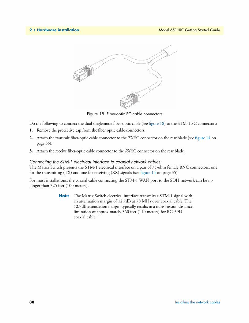
Figure 18. Fiber-optic SC cable connectors
Do the following to connect the dual singlemode fiber-optic cable (see figure 18) to the STM-1 SC connectors:
1. Remove the protective cap from the fiber optic cable connectors.
2. Attach the transmit fiber-optic cable connector to the TX SC connector on the rear blade (see figure 14 on page 35).
3. Attach the receive fiber-optic cable connector to the RX SC connector on the rear blade.
Connecting the STM-1 electrical interface to coaxial network cablesThe Matrix Switch presents the STM-1 electrical interface on a pair of 75-ohm female BNC connectors, one for the transmiting (TX) and one for receiving (RX) signals (see figure 14 on page 35).
For most installations, the coaxial cable connecting the STM-1 WAN port to the SDH network can be no longer than 325 feet (100 meters).
Note The Matrix Switch electrical interface transmits a STM-1 signal with an attenuation margin of 12.7dB at 78 MHz over coaxial cable. The 12.7dB attenuation margin typically results in a transmission distance limitation of approximately 360 feet (110 meters) for RG-59U coaxial cable.
38 Installing the network cables

Model 6511RC Getting Started Guide 2 • Hardware installation
Figure 19. BNC coaxial cable connectors
Do the following to connect the dual 75-ohm coaxial cable (see figure 19) to the STM-1 BNC connectors:
1. Attach the transmit connector of the coaxial cable to the TX connector on the rear blade (see figure 14 on page 35).
2. Attach the transmit connector of the coaxial cable to the RX connector on the rear blade.
Connecting the rear-panel Ethernet WAN/management portsThe Matrix Switch provides two 10/100/1000Base-T Ethernet transceivers, accessible via physical interfaces on the rear-panel of the rear blade, for connection to an external router, hub, or switch. Both interfaces are pre-sented on RJ-45 6-pin female receptacles. The interfaces comply with IEEE specification 802.3 and are labeled ENET 1 and ENET 2 (see figure 14 on page 35).
Once connected to a LAN, the Ethernet port will autosense the speed of the LAN and automatically negotiate half or full-duplex operation. The ports provide access to the Matrix Switch’s resident management services, including the HTTP/web management feature. This port also connects to the on-board Ethernet switch, thus providing Ethernet access to other blades within the ForeFront system via the PICMG 2.16 PSB.
You can use the two high-speed Ethernet ports to implement the following functions:
• Ethernet trunks. You can connect the 10/100/100 Ethernet ports to a WAN router in order to deliver high-speed aggregated packet-based traffic to and from the ForeFront system over packet-switched WAN trunks. The WAN router would then be connected to a private WAN or to the Internet.
• Ethernet management network. You can connect the 10/100/100 Ethernet ports to a local area network via an external hub or switch in order to implement an out-of-band management network. To create an external management network, all ForeFront blades must connect to the management LAN via an Ethernet port residing on each blade. The Matrix Switch also offers access to an internal management network, the PICMG 2.16 PSB. By means of its on-board Ethernet switch, the Matrix Switch provides a packet-switched path to all blades operating on the same PICMG 2.16 bus, which a Network Management System can use to communicate with the management services on those blades.
Installing the network cables 39
2 • Hardware installation Model 6511RC Getting Started Guide
Connecting the 10/100/1000 Base-T Ethernet ports to a router, hub or switchThe 10/100/100Base-T Ethernet ports may be connected to a WAN router, or to an Ethernet hub or switch. To connect the router, hub or switch to the Matrix Switch, you must use a straight-through CAT-5 RJ-45 cable (one wired as shown in figure 15 on page 36). Figure 15 shows the Ethernet RJ-45 pin and signal defi-nitions for the Matrix Switch. For cable distance limitations please consult the IEEE specification 802.3.
To connect the 10/100/100 Base-T Ethernet port to a router, hub or switch:
1. Connect the RJ-45 connector at one end of the cable into the 6-pin RJ-45 receptacle on the rear-panel of the 6511RC rear-blade.
2. Connect the RJ-45 connector at other end of the cable into the 6-pin RJ-45 receptacle on the router, hub, or switch.
Completing the hardware installationThis section verifies that the Matrix Switch hardware is operational to the point where you can begin configur-ing the software settings.
Power is delivered from the CPCI chassis backplane through the 47-pin PICMG 2.11 power connectors on the 6511RC blades. Upon insertion into the CPCI chassis, the Model 6511RC immediately powers up and begins its boot cycle. During the boot cycle the following should occur:
1. The POWER LED illuminates, indicating normal power is being applied to the 6511RC.
2. The green SYSTEM LED begins flashing, indicating the 6511RC is operating normally.
Hardware installation is now complete. To configure the 6511RC for operation, refer to chapter 3, “Configur-ing the Matrix Switch for operation” on page 41.
40 Completing the hardware installation
Chapter 3 Configuring the Matrix Switch for operation
Chapter contentsIntroduction ..........................................................................................................................................................42Configuration prerequisites ...................................................................................................................................42Initial configuration through the RS-232 control port ...........................................................................................43
Connecting the DB9-RJ45 adapter with the included cable ............................................................................43Setting up the HyperTerminal (or similar program) session ............................................................................44
Using a browser to complete Model 6511RC configuration ..................................................................................47Displaying the Matrix Switch 6511RC web administration pages ...................................................................47
Home page overview .................................................................................................................................49Configuring the default gateway .....................................................................................................................51Configuring the system clocking parameters ...................................................................................................52
Module clocking mode ..............................................................................................................................52Module clocking source and fallback .........................................................................................................53
Example 1 ........................................................................................................................................... 53Example 2 ........................................................................................................................................... 54
Configuring the SDH circuit parameters ........................................................................................................54Accessing the SDH circuit parameters .......................................................................................................55Configuring the SDH physical interface type ............................................................................................56Configuring the SDH interface parameters ...............................................................................................56Configuring the SDH path trace parameters .............................................................................................57
Configuring DS0 idle codes ............................................................................................................................58Accessing the idle code configuration ........................................................................................................59Defining the DS0 idle code configuration .................................................................................................60
Selecting the SDH mapping path ....................................................................................................................60
Defining DS0 mappings .................................................................................................................................62Defining DS0 mappings using E1 port format ..........................................................................................64Examples for configuring DS0 mappings. .................................................................................................65Defining DS0 mappings using TU format ................................................................................................69Examples for configuring DS0 mappings. .................................................................................................72
Saving your configuration ...............................................................................................................................74Backing up your configuration parameters.............................................................................................................75
Backing up the configuration store in flash memory .......................................................................................76Completing the installation ...................................................................................................................................77
41

3 • Configuring the Matrix Switch for operation Model 6511RC Getting Started Guide
IntroductionThis chapter contains the following procedures that describe configuring the Model 6511RC Matrix Switch for operation:
• “Configuration prerequisites”—lists the items you need to have on hand before configuring the Matrix Switch.
• “Initial configuration through the RS-232 control port” on page 43—describes how to define the 6511RC’s LAN IP address and netmask parameters.
• “Using a browser to complete Model 6511RC configuration” on page 47—describes how to define the remaining basic configuration parameters in order to bring your Matrix Switch on-line. The procedures include the following steps:
- Displaying the Matrix Switch home page (see “Displaying the Matrix Switch 6511RC web administration pages” on page 47)
- Defining the IP default gateway (see “Configuring the default gateway” on page 51)
- Defining the system clocking parameters (see “Configuring the system clocking parameters” on page 52
- Defining the STM-1 Circuit parameters (see “Configuring the SDH circuit parameters” on page 54)
- Enabling idle code generation for designated DS0 channels (see “Configuring DS0 idle codes” on page 58)
- Defining DS0 mappings within the STM-1 link (see “Selecting the SDH mapping path” on page 60)
• “Saving your configuration” on page 74—describes how to save your configuration settings.
• “Backing up your configuration parameters” on page 75—describes how save your configuration parame-ters to a file
• “Completing the installation” on page 77—describes how to verify that your 6511RC Matrix Switch is fully operational.
Configuration prerequisitesYou will need the following to configure the 6511RC Matrix Switch:
• A PC equipped with the following:
- RS-232/V.24 serial port
- VT-100 terminal program, e.g., HyperTerminal
- Ethernet port
- Web browser (e.g., Netscape Communicator or Microsoft Internet Explorer)
• You will need the following information to configure the Model 6511RC:
- The IP address and subnet mask for the 6511RC’s Ethernet port
- The IP address of the default gateway
• To configure the STM-1 link, you will need the following information from the SDH network to which you are connecting:
42 Introduction

Model 6511RC Getting Started Guide 3 • Configuring the Matrix Switch for operation
- Which E1 mapping path will be used within the STM-1 link, either AU3 or AU4.
- Section Trace Message Length
- The value of the JO byte for Section Trace Messages
- Path-1 Trace Message Length
- The value of the J1 byte for Path-1 Trace Messages
- The value of Path-1 Signal Label
- The E1 payload type, either asynchronous or byte synchronous
• To configure the DS0 mappings, you will need
- a detailed plan describing the desired source and destination for each of the 4096 simplex DS0 channels within the H.110 bus on the chassis mid-plane
- which DS0 channels within each E1 signal stream should carry an idle code
Initial configuration through the RS-232 control portInitially you must configure the 6511RC’s IP address via the RS-232 Config port located on the Matrix Switch front frame. In rare instances, you may also need to change the netmask from the factory default value.
Note The Model 6511RC must be installed, powered-up, and operating before you can perform the initial configuration. If it is not, you must first complete the procedures described in chapter 2, “Hardware installation” on page 31.
Connecting the DB9-RJ45 adapter with the included cableDo the following:
1. Find the DB9-RJ45 adapter for your PC and RJ-45-to-RJ45 cable shipped with your 6511RC Matrix Switch.
2. Connect the DB9-RJ45 adapter to your PC’s RS-232 serial port.
3. Connect the RJ45-RJ45 cable between the adapter that you installed in step 1 and the CONFIG port on the front of the Model 6511RC (figure 20).
Figure 20. Model 6511RC interface ports
Initial configuration through the RS-232 control port 43

3 • Configuring the Matrix Switch for operation Model 6511RC Getting Started Guide
Setting up the HyperTerminal (or similar program) sessionDo the following:
1. At your PC, find the file HYPERTRM.EXE. Open a HyperTerminal session by double-clicking on the file name.
Figure 21. Connection Description window
2. Type a connection name (e.g., 6511RC Config), select an icon, then click OK (figure 22).
Figure 22. Connect To window
3. On the Connect To window (figure 22), set Connect using: to one of the options named Direct to ComX (where the “X” refers to the number identifying the RS-232 serial port on the PC). In the following proce-dure, Com1 will be the used as the port identifier.
4. Click OK .
5. The COM1 Properties window displays.
44 Initial configuration through the RS-232 control port
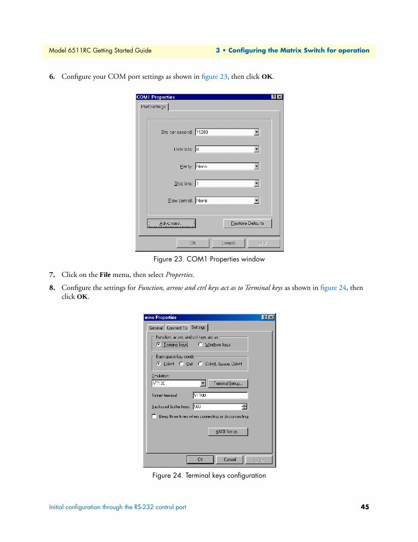
Model 6511RC Getting Started Guide 3 • Configuring the Matrix Switch for operation
6. Configure your COM port settings as shown in figure 23, then click OK .
Figure 23. COM1 Properties window
7. Click on the File menu, then select Properties.
8. Configure the settings for Function, arrow and ctrl keys act as to Terminal keys as shown in figure 24, then click OK .
Figure 24. Terminal keys configuration
Initial configuration through the RS-232 control port 45

3 • Configuring the Matrix Switch for operation Model 6511RC Getting Started Guide
9. Connect the male end of the 6511RC Matrix Switch’s power cables to the power outlets.
10. Boot up information will display on your HyperTerminal connection window, eventually followed by a login request window (see figure 25).
Figure 25. Login window
11. For the user name, type superuser.
12. For the password, type superuser; the TOP LEVEL MANAGEMENT window then appears (see figure 26).
Figure 26. VT-100 Top Level Management window
13. Type k for System, then press <Enter>.
14. Under System, type 1 for Details, then press <Enter>.
15. Enter g for LAN Address, then press <Enter>.
16. Type your LAN IP address followed by pressing <Enter>.
17. Press the left-arrow cursor key on your keyboard to return to the previous screen.
18. If you do not need to change the LAN Mask from the default of 255.255.255.0, go to step 21. Otherwise, press h and type the new LAN Mask in the same manner as when entering a LAN IP address.
46 Initial configuration through the RS-232 control port
Model 6511RC Getting Started Guide 3 • Configuring the Matrix Switch for operation
19. Press the left-arrow cursor key until the TOP LEVEL MANAGEMENT window displays.
20. Select a for Home, then press <Enter>.
21. Under the Current Status page, type 1 (store Config(1)) to save the changes you have just made to the con-figuration.
This completes the initial configuration of the Model 6511RC. The next steps in configuration will be done using your web browser connected via Ethernet to the 6511RC.
Using a browser to complete Model 6511RC configurationThis section describes the following procedures:
• Displaying the Matrix Switch home page (see section “Displaying the Matrix Switch 6511RC web adminis-tration pages” on page 47)
• Defining the IP default gateway (see section “Configuring the default gateway” on page 51)
• Defining the system clocking parameters (see section “Configuring the system clocking parameters” on page 52)
• Defining the STM-1 Circuit parameters (see section “Configuring the SDH circuit parameters” on page 54)
• Enabling idle code generation for designated DS0 channels (see section “Configuring DS0 idle codes” on page 58)
• Defining DS0 mappings within the STM-1 link (see section “Selecting the SDH mapping path” on page 60)
Displaying the Matrix Switch 6511RC web administration pagesDo the following:
1. Connect your PC’s Ethernet connection to the Ethernet LAN.
2. Connect the 6511RC’s Matrix Switch 10/100 Ethernet port to the Ethernet LAN.
3. At your PC, open a web browser session. In your browser’s URL/address field type the IP address of the Model 6511RC (for example, if the Model 6511RC’s IP address 123.124.221.10, you would type 123.124.221.10 in the browser’s URL/address field). If you do not have an IP address in your TDAC, refer to “Initial configuration through the RS-232 control port” on page 43.
4. A login prompt will appear. In the username field type superuser then press <Tab> to move the cursor to the Password field. In the password field type superuser then press <Enter>.
Using a browser to complete Model 6511RC configuration 47
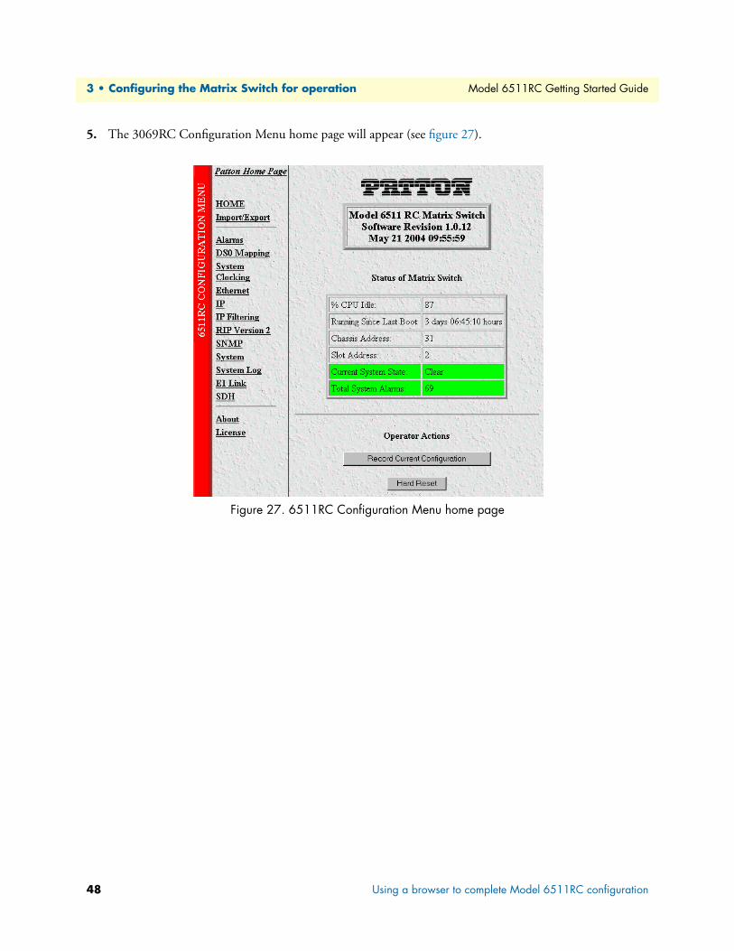
3 • Configuring the Matrix Switch for operation Model 6511RC Getting Started Guide
5. The 3069RC Configuration Menu home page will appear (see figure 27).
Figure 27. 6511RC Configuration Menu home page
48 Using a browser to complete Model 6511RC configuration

Model 6511RC Getting Started Guide 3 • Configuring the Matrix Switch for operation
Home page overviewThe HOME window is divided into two panes: the Configuration Menu pane and the Configuration/Informa-tion pane (see figure 28). The Configuration Menu contains the links to the various Model 6511RC sub-systems, while in the Configuration/Information pane, you can view status and other information or make changes to the system configuration. Unlike the Configuration Menu pane, which appears the same no matter which subsystem page you may select, the Configuration/Information pane contents will change as you move from one subsystem page to another.
Figure 28. HOME page window panes
Using a browser to complete Model 6511RC configuration 49

3 • Configuring the Matrix Switch for operation Model 6511RC Getting Started Guide
Figure 29. Operator Actions buttons
From the Home page, the following actions can be performed:
• Record Current Configuration—clicking on this button (see figure 29) saves the current configuration from volatile DRAM memory to FLASH memory. Once the configuration is saved into FLASH memory, the configuration will not be lost even if the power is cycled on the 6511RC. Initially, changes made to the 6511RC configuration are stored in volatile DRAM, enabling the user to set the box up with a working configuration before committing it to storage in FLASH. When you select Record Current Configuration, the 6511RC stores your changes to FLASH memory.
Note If you want to save the configuration changes that you have made, you must click on Record Current Configuration, otherwise all con-figuration changes will be lost if the power to the Model 6511RC is turned off.
• Hard Reset—this button (see figure 29) causes the Model 6511RC to perform a cold restart. When you select Hard Reset, the Matrix Switch confirms that you want to execute this command. Then, the Matrix Switch will disconnect all current sessions, re-initialize the interfaces, and re-load configuration parameters from FLASH.
• Set Factory Default Configuration—this button (see figure 29) clears out the configuration in FLASH and loads the factory default parameters into FLASH memory. The factory default settings will not execute on the Model 6511RC until it is re-booted by doing a Hard Reset.
Note Set Factory Default Configuration (figure 29) will delete the Model 6511RC’s Ethernet IP address, any routing information, and any other site-specific configuration changes made for your particular installation. You will have to re-enter the Model 6511RC’s Ethernet IP address and netmask using the front-panel control port in order to gain access the HTTP/HTML Management pages again.
50 Using a browser to complete Model 6511RC configuration

Model 6511RC Getting Started Guide 3 • Configuring the Matrix Switch for operation
Configuring the default gatewayThe default gateway IP address, if defined, is used solely for managing the 6511RC remotely via the Ethernet port. The 6511RC does not transmit or receive user data nor any other traffic via the default gateway IP address or the Ethernet port.
Do the following to add the default gateway:
1. On the 6511RC Configuration Menu (see figure 27 on page 48), click the IP hyperlink to open the IP Overview page (see figure 30).
Figure 30. IP Overview page
2. Click the Routing Info hyperlink to open the IP Routing Overview page (figure 31).
Figure 31. IP Routing Overview page
Using a browser to complete Model 6511RC configuration 51

3 • Configuring the Matrix Switch for operation Model 6511RC Getting Started Guide
3. The Defined Routes table (see figure 32) will contain exactly one route, displayed in the first row of the table. The 6511RC created this route automatically when you defined the Ethernet IP address during Ini-tial Configuration, earlier in this chapter. That first row displays the route and netmask for the primary IP address you defined for the Matrix Switch Ethernet interfaces.
Figure 32. Defined Routes table
4. You will use the first row in the Define a New Route table (see figure 33) to define the default gateway. The Destination field contains the value 0.0.0.0. Because the netmask for the default gateway is implied by the Matrix Switch’s primary IP address, the Mask field does not display. In the Gateway field, enter your 6511RC’s default gateway IP address.
Figure 33. Define a New Route table
5. Click the Define button (see figure 33) to activate the new default gateway address.
Configuring the system clocking parametersIn this section you will define the system clocking configuration for the Matrix Switch. Three issues pertain to system clocking:
• Module clocking mode—Will this Matrix Switch serve as a Master timing source for the other modules on the H.110 bus? (See section “Module clocking mode” for details.)
• Module clocking source—What clock pulse will the Matrix Switch use for primary reference and alternate (fallback) reference. (See section “Module clocking source and fallback” on page 53 for details.)
• Module clocking fallback—Will you enable or disable the clocking fallback feature in case the primary reference fails? (See section “Module clocking source and fallback” on page 53 for details.)
Module clocking modeModule clocking mode defines what role the Matrix Switch will assume on the H.110 bus with respect to sys-tem timing. You can select master(1), secondary(2), or slave(3) for the value of Clocking Mode. The master will drive the main reference clock for the chassis. Should the master fail, the secondary will drive the main refer-
52 Using a browser to complete Model 6511RC configuration

Model 6511RC Getting Started Guide 3 • Configuring the Matrix Switch for operation
ence. Slaves will not drive any clock reference. Most often the 6511RC will be defined as the master(1), while most other modules in the chassis will be defined as slave(3).
Module clocking source and fallbackThere are two module clocking source parameters, the primary reference and the fallback reference. Unless it fails or becomes disconnected, the primary reference provides the system clock for the 6511RC. Should this failure occur, the fallback reference will become the clocking source for the 6511RC’s system clock.You must choose one of the following values as the clocking source for each reference:
• An internal oscillator
• The STM-1 port
• The system clock provided by the H.110 clocking master, (i.e. another module in the chassis).
The following examples illustrate how to define the system clocking parameters for two scenarios.
Example 1. In this example, your 6511RC will be the clocking master for all other modules on the same H.110 bus. Your 6511RC will derive its own timing from its STM-1 port as the main reference, and from its internal oscillator as the fallback reference. To define the system clocking parameters:
1. Connect a STM-1 WAN line to the 6511RC’s STM-1 port.
2. Click the System Clocking hyperlink on the 6511RC Configuration Menu (see figure 27 on page 48) to open the System Clocking Overview page (see figure 34).
Figure 34. System Clocking Overview page, example 1
3. For Module Clocking Mode, select master(1) from the drop-down menu.
4. Under Module Clocking Source, for Primary Reference select wan(602) from the drop-down menu.
5. For Fallback Reference select internal(200) from the drop-down menu.
6. Under Module Clocking Fallback, for Fallback Feature Desired State, select enable(1).
7. Click the Modify button.
Using a browser to complete Model 6511RC configuration 53

3 • Configuring the Matrix Switch for operation Model 6511RC Getting Started Guide
Example 2. For this example, another Matrix Switch is the chassis is the clocking master, providing the system clock for the chassis, and your 6511RC is a slave. Your 6511RC will derive its timing from the H.110 bus sys-tem clock as the main reference, and from its STM-1 port as the fallback reference. To define the system clock-ing parameters:
1. Connect a STM-1 WAN line to the 6511RC’s STM-1 port.
2. Click the System Clocking hyperlink on the 6511RC Configuration Menu (see figure 27 on page 48) to open the System Clocking Overview page (see figure 35).
Figure 35. System Clocking Configuration page, example 2
3. For Module Clocking Mode, select slave(2) from the drop-down menu.
4. Under Module Clocking Source, for Primary Reference select system(600) from the drop-down menu.
5. For Fallback Reference select wan(602) from the drop-down menu.
6. Under Module Clocking Fallback, for Fallback Feature Desired State, select enable(1).
7. Click the Modify button.
Configuring the SDH circuit parametersIn order for the STM-1 link to function correctly, you must correctly define the values of certain configurable parameters that affect the SDH circuit. In order to configure the STM-1 link, you must first gather the follow-ing information:
• Which E1 mapping path—either AU3 or AU4—will be used within the STM-1 link
• Section trace message length
• The value of the JO byte for section trace messages
• Path-1 trace message length
• The value of the J1 byte for path-1 trace messages
• The value of path-1 signal label
• The E1 payload type, either asynchronous or byte synchronous
54 Using a browser to complete Model 6511RC configuration
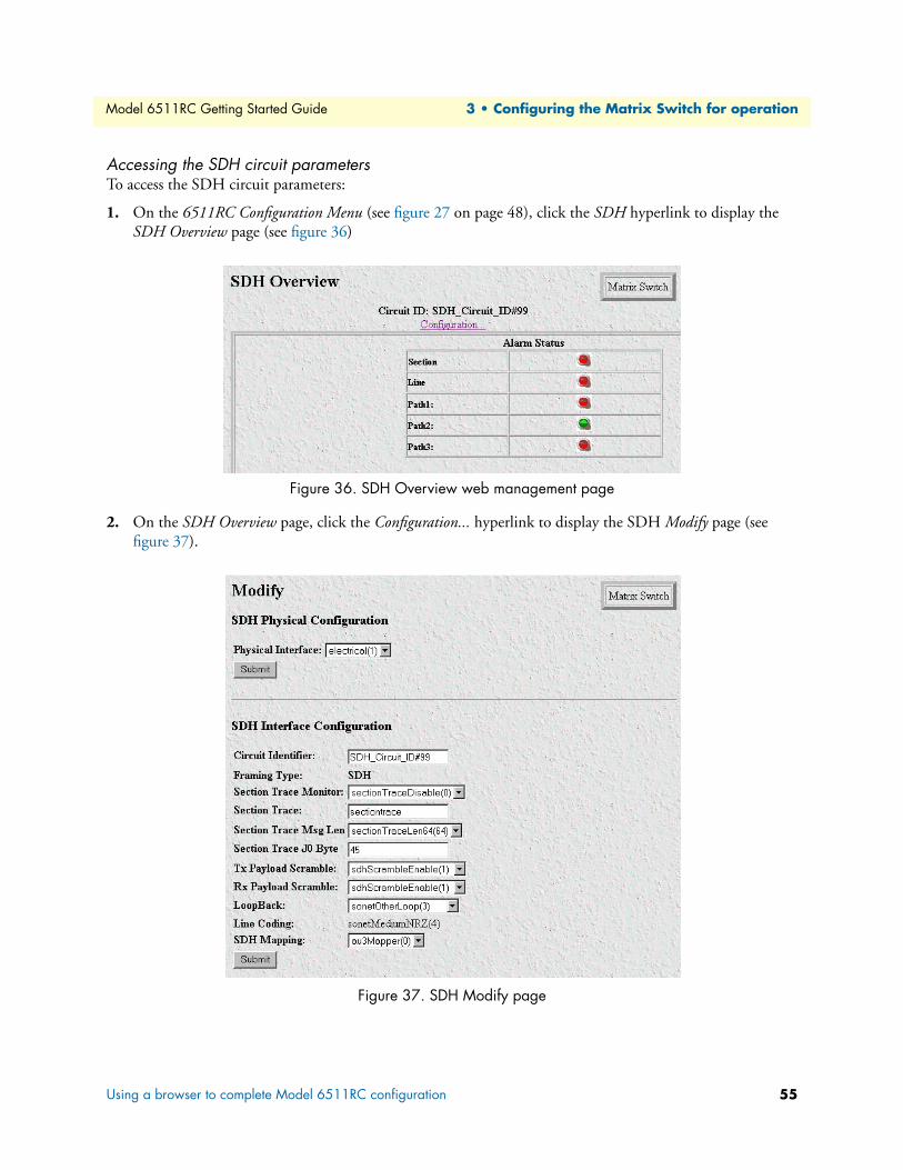
Model 6511RC Getting Started Guide 3 • Configuring the Matrix Switch for operation
Accessing the SDH circuit parametersTo access the SDH circuit parameters:
1. On the 6511RC Configuration Menu (see figure 27 on page 48), click the SDH hyperlink to display the SDH Overview page (see figure 36)
.
Figure 36. SDH Overview web management page
2. On the SDH Overview page, click the Configuration... hyperlink to display the SDH Modify page (see figure 37).
Figure 37. SDH Modify page
Using a browser to complete Model 6511RC configuration 55

3 • Configuring the Matrix Switch for operation Model 6511RC Getting Started Guide
Configuring the SDH physical interface typeDo the following to define the physical interface type providing the STM-1 link:
1. In the SDH Physical Configuration section (see figure 38), select from the Physical Interface drop-down menu the value that corresponds to the physical cabling attached to your STM-1 interface ports. If you are using fiber-optic cable connected to the rear-card SC connectors, then select optical(0). If you are using coaxial cables connected to the rear-card BNC connectors, then select electrical(1).
Figure 38. SDH Physical Configuration section
2. Click the Submit button to activate your selection.
Configuring the SDH interface parameters1. In the SDH Interface Configuration section (see figure 39), for Circuit Identifier, enter an optional alphanu-
meric name for this STM-1 link.
Figure 39. SDH Interface Configuration section
2. If section trace is enabled in your connected SDH network, go to step 3. Otherwise, because section trace is disabled, for the Section Trace Monitor parameter, select sectionTraceDisable(0) from the drop-down menu, then go to step 7 to define the value of the SDH Payload Mapping parameter.
3. Because section trace is enabled in your connected SDH network, for the Section Trace Monitor parame-ter, select sectionTraceEnable(1) from the drop-down menu.
4. For the Section Trace message string, enter the alphanumeric string your connected SDH network uses for the section trace message string in the SDH frame.
Note The Section Trace parameter only applies with 16-byte and 64-byte section trace messages. For 1-byte trace messages, the J0 byte parame-
56 Using a browser to complete Model 6511RC configuration

Model 6511RC Getting Started Guide 3 • Configuring the Matrix Switch for operation
ter applies. When the section trace message length is defined to be one byte, the Matrix Switch will ignore the value of Section Trace.
5. For Section Trace Msg Len, from the drop-down menu, select the value used by the SDH network your Matrix Switch is connected to: either 1, 16, or 64-byte trace messages.
6. For Section Trace J0 Byte enter the value your connected SDH network uses for the J0 byte in the SDH frame.
Note J0 applies only with 1-byte Section Trace Messages. For 16-byte and 64-byte trace messages, the trace message string applies and the value of J0 is ignored.
7. For SDH Payload Mapping, select the payload type corresponding to the way your connected SDH net-work maps the E1 payload into the SDH frame structure. Asynchronous E1 payload mapping is most common, so the factory default value on the Matrix Switch is stm1MappedAsynchE1(0). If your connected SDH network performs byte-synchronous E1 payload mapping, then select stm1MappedBytesynchE1(1) from the drop-down menu.
8. For Tx Payload Scramble, if your SDH network expects to receive a scrambled payload select SDHScram-bleEnable(1) from the drop-down menu, otherwise select sdhScrambleDisable(0).
9. For Rx Payload Scramble, if your SDH network transmits a scrambled payload select SDHScrambleEn-able(1) from the drop-down menu, otherwise select sdhScrambleDisable(0).
10. For SDH Mapping, select the type of AU corresponding to the SDH multiplexing path you desire. To mul-tiplex seven TUG-2s into an AU-3, select au3Mapper(0) (the factory default) from the drop-down menu. To multiplex three TUG-3s into an AU-4, select au4Mapper(1).
11. Click the Modify button to save your work into operating memory (volatile DRAM) and activate the new parameter values.
Configuring the SDH path trace parametersIf you selected AU-4 mapping in the preceding procedure, the Matrix Switch will display one set of five parame-ters pertaining to Path 1. If you selected AU-3 mapping, the Matrix Switch will display three sets of five parame-ters each pertaining to Paths 1, 2, and 3. Do the following to define the values for the SDH path trace parameters:
1. If path trace is enabled in your connected SDH network, go to step 2. Otherwise, because path trace is disabled, in the SDH trace parameters table (see figure 40), for Path-1 Trace Monitor, select pathTraceDis-able(0) from the drop-down menu. Refer to section “Configuring DS0 idle codes” on page 58.
Figure 40. SDH Path Trace parameters
Using a browser to complete Model 6511RC configuration 57

3 • Configuring the Matrix Switch for operation Model 6511RC Getting Started Guide
2. Because path trace is enabled in your connected SDH network, in the SDH trace parameters table (see figure 40 on page 57), for Path-1 Trace Monitor, select pathTraceEnable(1) from the drop-down menu.
3. For Path-1 Trace message, enter the alphanumeric string your connected SDH network uses for the path-1 trace message in the text box.
Note The Path-1 Trace message parameter only applies with 16-byte and 64-byte section trace messages. For 1-byte path trace messages, the J1 byte parameter applies. When trace message length is defined to be one byte, the Matrix Switch will ignore the value of Path-1 Trace.
4. For Path-1 Trace Msg Len, select the value corresponding to the trace message length your connected SDH network uses.
5. For Path-1 Trace J1 Byte, enter the value your connected SDH network uses for the J1 byte in the SDH frame.
Note J1 applies only with 1-byte path trace messages. For 16-byte and 64-byte trace messages, the trace message string is used and the value of J1 is ignored.
6. For Path-1 Signal Label, enter the value your connected SDH network uses for the path-1 signal label in the SDH frame.
7. If you have selected AU-3 mapping, repeat steps 1 through 6 to define values for the path-2 and path-3 trace parameters.
8. Click the Modify button to save your work into operating memory (volatile DRAM) and activate the new parameter values.
Configuring DS0 idle codesIf you want your Matrix Switch to encode vacant DS0 channels with the standard E1 idle code (the hexadeci-mal value 7E), you must follow the procedures below to designate which DS0 channels within the STM-1 sig-nal stream should be so encoded. Obviously, in order to correctly define the idle code configuration, you must know which DS0 channels in the SDH frame are expected to be idle. Defining the idle code configuration involves two steps: you must first access the DS0 Idle Code Configuration web management page, then use that page to select the idle DS0 channels from the STM-1 structure and designate them as idle.
58 Using a browser to complete Model 6511RC configuration

Model 6511RC Getting Started Guide 3 • Configuring the Matrix Switch for operation
Accessing the idle code configurationDo the following to access the Matrix Switch’s idle code configuration:
1. On the 6511RC Configuration Menu (see figure 27 on page 48), click the E1 Link hyperlink to display the E1 Link page (see figure 41).
Figure 41. E1 Link page
2. To view all of the 63 E1s within the STM-1 link, first ensure that:
– tug3ALL(0) is selected next to the label TUG3
– tug2ALL(0) is selected next to the label TUG2
then click the Submit Query button to display the next page showing E1 link status (see figure 42).
Figure 42. Page showing E1 link status
This page displays all 63 E1 links according to their position within the STM-1 mapping structure: each E1 resides within a tributary unit (TU), 3 TUs reside within each level-2 tributary unit group (TUG-2). The final level of multiplexing concentrates 7 TUG-2s within either a level-3 administrative unit group (AUG-3), or a level-3 tributary unit group (TUG-3). The TUG-3 then resides within a level-4 administra-tive unit group (AUG-4).
Using a browser to complete Model 6511RC configuration 59
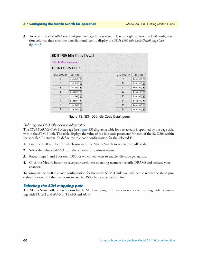
3 • Configuring the Matrix Switch for operation Model 6511RC Getting Started Guide
3. To access the DS0 Idle Code Configuration page for a selected E1, scroll right to view the DS0 configura-tion column, then click the blue diamond icon to display the SDH DS0 Idle Code Detail page (see figure 43).
Figure 43. SDH DS0 Idle Code Detail page
Defining the DS0 idle code configurationThe SDH DS0 Idle Code Detail page (see figure 43) displays a table for a selected E1, specified by the page title, within the STM-1 link. The table displays the value of the idle code parameter for each of the 32 DS0s within the specified E1 stream. To define the idle code configuration for the selected E1:
1. Find the DS0 number for which you want the Matrix Switch to generate an idle code.
2. Select the value enable(1) from the adjacent drop-down menu.
3. Repeat steps 1 and 2 for each DS0 for which you want to enable idle code generation.
4. Click the Modify button to save your work into operating memory (volatile DRAM) and activate your changes.
To complete the DS0 idle code configuration for the entire STM-1 link, you will ned to repeat the above pro-cedures for each E1 that you want to enable DS0 idle code generation for.
Selecting the SDH mapping pathThe Matrix Switch offers two options for the SDH mapping path: you can select the mapping path terminat-ing with TUG-2 and AU-3 or TUG-3 and AU-4.
60 Using a browser to complete Model 6511RC configuration
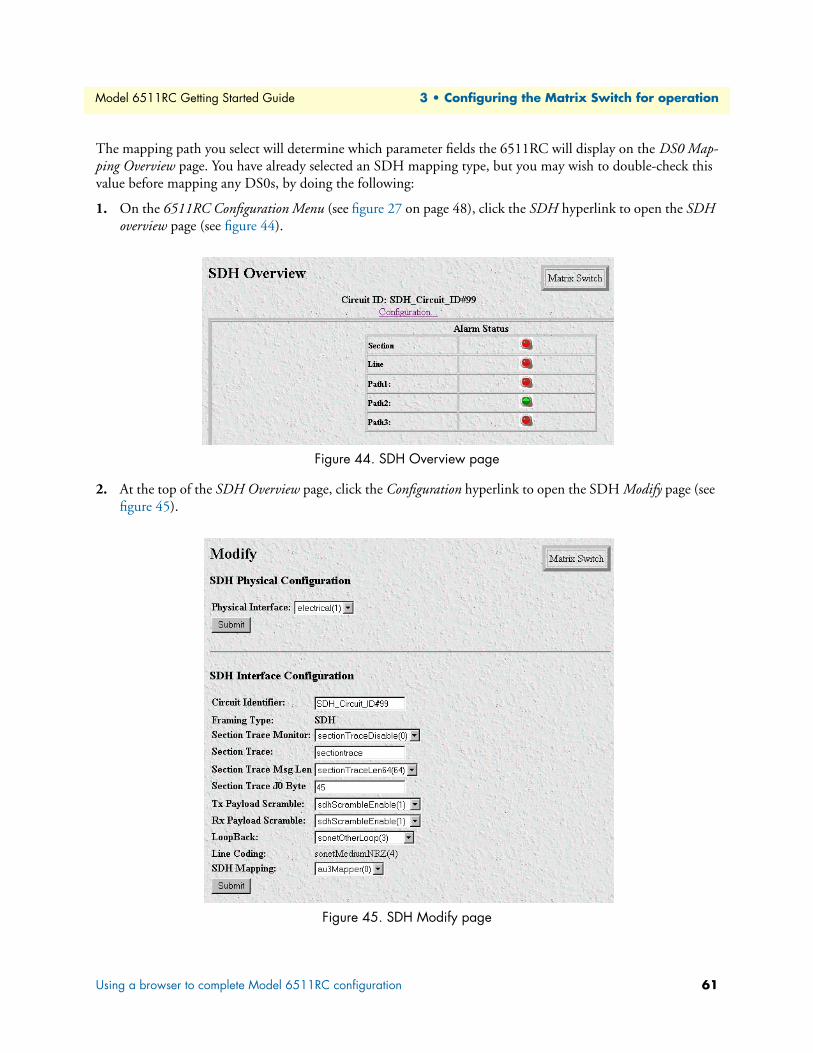
Model 6511RC Getting Started Guide 3 • Configuring the Matrix Switch for operation
The mapping path you select will determine which parameter fields the 6511RC will display on the DS0 Map-ping Overview page. You have already selected an SDH mapping type, but you may wish to double-check this value before mapping any DS0s, by doing the following:
1. On the 6511RC Configuration Menu (see figure 27 on page 48), click the SDH hyperlink to open the SDH overview page (see figure 44).
Figure 44. SDH Overview page
2. At the top of the SDH Overview page, click the Configuration hyperlink to open the SDH Modify page (see figure 45).
Figure 45. SDH Modify page
Using a browser to complete Model 6511RC configuration 61

3 • Configuring the Matrix Switch for operation Model 6511RC Getting Started Guide
3. Scroll down to the SDH mapping parameter and select the appropriate mapping path from the drop-down menu. Select au3Mapper(0) or au4Mapper(1). To multiplex seven TUG-2s into an AU-3, select au3Mapper(0) (the factory default) from the drop-down menu. To multiplex three TUG-3s into an AU-4, select au4Mapper(1).
4. Click the Submit button to save changes.
You are now ready to define DS0 mappings.
Defining DS0 mappingsIn order for the STM-1 link to carry traffic through the Matrix Switch to and from the ForeFront system, you must define a set of DS0 mappings (correlations). You will define mappings between the full-duplex DS0s within the STM-1 link and the simplex DS0s within the H.110 bus. While it is not necessary to define a map-ping for every DS0 in the SDH link, only the mapped DS0s will carry user data. Unmapped DS0s may be configured to carry an idle code. Otherwise, unmapped DS0s will carry a random bit stream.
For each DS0 Mapping you define, you will create a correlation between a communications channel in the STM-1 link and a communications channel within the ForeFront chassis mid-plane. Each STM-1 channel consists of a set of full-duplex DS0s. Each midplane channel consists of two simplex sub-channels, transmitted and received. Each sub-channel consists of a set of simplex DS0s. You will define each STM-1 channel and each mid-plane sub-channel by specifying one or more timeslot numbers up to a maximum of 32 timeslots per channel. For a STM-1channel you will select up to 32 timeslot numbers from the range numbered 1 to 32. For a mid-plane channel you will select up to 32 timeslots from the range numbered 1 to 128.
On the STM-1 side, there are 63 E1 signal streams, each comprising 32 DS0s. Within an E1, each DS0 is a full-duplex channel, comprising a transmitted and a received signal stream. The STM-1 link comprises 2016 full-duplex DS0s.
On the mid-plane side, there are 4096 simplex DS0s within the H.110 bus, organized into 32 ports. Each H.110 port comprises 128 DS0s. Within the H.110 bus, each DS0 is a simplex signal stream, which the H.110 bus can either transmit or receive. You will define the direction of a mid-plane DS0 during the mapping process as either transmitting to the H.110 bus or receiving from the H.110 bus. The H.110 bus provides 4096 simplex DS0s.
When entering E1 and H.110 timeslot numbers, you must define the same number of timeslots on the SDH and mid-plane sides of the mapping. The timeslots are defined by entering a text string that represents the timeslot numbers.
The following notation should be used for assigning timeslots:
• dash: (-), e.g., 1-4
• comma: (,), e.g., 1,4,9
• combo: 1-2,3,6-7
62 Using a browser to complete Model 6511RC configuration

Model 6511RC Getting Started Guide 3 • Configuring the Matrix Switch for operation
The Matrix Switch offers two formats for defining DS0 mappings:
• E1 port format—You will identify the 63 E1 signal streams within the STM-1 link using E1 port numbers 1-63. Those with little to moderate experience working with SDH network architecture will most likely find E1 format to be the simplest and most straightforward method for defining DS0 mappings. Refer to section “Defining DS0 mappings using E1 port format” on page 64.
• TU format—You will identify an E1 signal stream according to its location within the STM-1 hierarchy, using the TU-12 number and TUG-2 number within an AUG-3 or within a TUG-3/AUG-4. Experienced SDH engineers with a clear understanding of STM-1 architecture will most likely prefer to use TU format to define DS0 mappings. Refer to section “Defining DS0 mappings using TU format” on page 69.
Figure 46 shows the position of each E1 port number within the STM-1 frame.
Figure 46. E1 Port numbers located within the STM-1 frame structure
The following sections describe how to define DS0 mappings.
Using a browser to complete Model 6511RC configuration 63

3 • Configuring the Matrix Switch for operation Model 6511RC Getting Started Guide
Figure 47. DS0 Mapping Overview page
Defining DS0 mappings using E1 port formatFor those with little to moderate experience in working with SDH network architecture, E1 format will most likely the simplest and most straightforward method for defining DS0 mappings. To define a DS0 mapping by E1 number, do the following:
1. On the 6511RC Configuration Menu (see figure 27 on page 48), click the DS0 Mapping hyperlink to dis-play the DS0 Mapping Overview page (see figure 47).
2. For the Display Option parameter, ensure that displayLongForm(0) is selected from the drop-down menu (figure 47), then click the Modify button.
3. For the E1 Input Format parameter, select e1PortFormat(1) from the drop down menu, then click the adja-cent Modify button.
4. In the Define a Mapping section, for E1 number, select the appropriate E1 port number from the drop-down menu.
5. For E1 Slots, type the timeslot numbers you wish to map to the H.110 bus.
When entering E1 and H.110 timeslot numbers you must define the same number of timeslots on the SDH and mid-plane sides of the mapping. The timeslots are defined by entering a text string that repre-sents the timeslot numbers.
64 Using a browser to complete Model 6511RC configuration

Model 6511RC Getting Started Guide 3 • Configuring the Matrix Switch for operation
The following notation should be used for assigning timeslots:
– dash: (-), e.g., 1 – 4
– comma: (,), e.g., 1,4,9
– combo: 1-2,3,6-7
At this point you have defined the SDH channel composed of a selected E1 signal stream and a set of timeslots within that E1. Now you must define the mid-plane channel to be correlated with the SDH channel.
6. In the first row, labeled to H110(5), for the H.110 number, select the appropriate H.110 port number from the drop-down menu
7. In the first row, labeled toH110(5), for H.110 slots, enter the timeslot numbers you wish to map to the H.110 bus (from the E1).
8. In the second row, labeled fromH110(6), select the appropriate H.110 port number from the drop-down menu
9. In the second row, labeled fromH110(6), for H.110 slots, enter the timeslot numbers you wish to map from the H.110 bus (to the E1).
10. Click the Define button. The new mapping will appear at the bottom of the page in the Defined Mappings table.
11. Examine the Defined Mappings table to verify that your new mapping appears and was correctly entered and recorded.
Examples for configuring DS0 mappings.
Three examples are provided:
• Example 1—For E1 port number 1:
- map all 32 timeslots of the received E1 signal to H.110 port 1 timeslots 1-32
- map all 32 timeslots of the transmitted E1 signal from H.110 port 1 timeslots 33-64
• Example 2—For E1 port number 2:
- map all 32 timeslots of the received E1 signal to H.110 port 1 timeslots 65-96
- map all 32 timeslots of the transmitted E1 signal from H.110 port 1 timeslots 97-128
• Example 3—For E1 port number 7
- map all 32 timeslots of the E1 received signal to H.110 port 4 timeslots 1-32
- map all 32 timeslots of the E1 transmitted signal from H.110 port 4 timeslots 33-64
Using a browser to complete Model 6511RC configuration 65

3 • Configuring the Matrix Switch for operation Model 6511RC Getting Started Guide
Example 1
Map E1 Port 1 received, timeslots 1-32 to H.110 Port 1 timeslots 1-32.
Map E1 Port 1 transmitted, timeslots 1-32 from H.110 Port 1 timeslots 33-64.
Solution:
1. Under E1 Number, select port1(1) from the drop-down menu (see figure 48).
2. Under E1 Slots, enter 1-32 in the text box.
3. For toH110(5), under H.110 Number, select port1(1) from the drop-down menu.
4. For toH110(5), under H.110 slots, enter 1-32 in the text box.
5. For fromH110(5), under H.110 Number, select port1(1) from the drop-down menu.
6. For fromH110(5), under H.110 slots, enter 33-64 in the text box.
Figure 48. Define a mapping table for Example 1
7. Click the Define button.
8. Verify your new mapping appears in the Defined Mappings table (see figure 49).
Figure 49. Defined Mappings table for example 1
9. Examine the new mapping to verify that it was entered and recorded correctly.
You have completed the DS0 mapping procedure for example 1.
66 Using a browser to complete Model 6511RC configuration
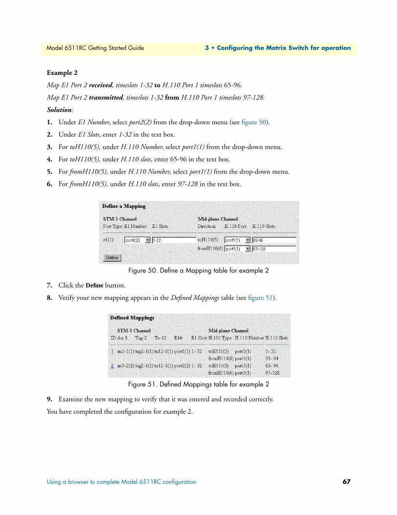
Model 6511RC Getting Started Guide 3 • Configuring the Matrix Switch for operation
Example 2
Map E1 Port 2 received, timeslots 1-32 to H.110 Port 1 timeslots 65-96.
Map E1 Port 2 transmitted, timeslots 1-32 from H.110 Port 1 timeslots 97-128.
Solution:
1. Under E1 Number, select port2(2) from the drop-down menu (see figure 50).
2. Under E1 Slots, enter 1-32 in the text box.
3. For toH110(5), under H.110 Number, select port1(1) from the drop-down menu.
4. For toH110(5), under H.110 slots, enter 65-96 in the text box.
5. For fromH110(5), under H.110 Number, select port1(1) from the drop-down menu.
6. For fromH110(5), under H.110 slots, enter 97-128 in the text box.
Figure 50. Define a Mapping table for example 2
7. Click the Define button.
8. Verify your new mapping appears in the Defined Mappings table (see figure 51).
Figure 51. Defined Mappings table for example 2
9. Examine the new mapping to verify that it was entered and recorded correctly.
You have completed the configuration for example 2.
Using a browser to complete Model 6511RC configuration 67

3 • Configuring the Matrix Switch for operation Model 6511RC Getting Started Guide
Example 3
Map E1 Port 7 received, timeslots 1-32 to H.110 Port 4 timeslots 1-32.
Map E1 Port 7 transmitted, timeslots 1-32 from H.110 Port 4 timeslots 33-64.
Solution:
1. Under E1 Number, select port7(7) from the drop-down menu (see figure 52).
2. Under E1 Slots, enter 1-32 in the text box.
3. For toH110(5), under H.110 Number, select port4(4) from the drop-down menu.
4. For toH110(5), under H.110 slots, enter 1-32 in the text box.
5. For fromH110(5), under H.110 Number, select port4(4) from the drop-down menu.
6. For fromH110(5), under H.110 slots, enter 33-64 in the text box.
Figure 52. Define a Mapping table for example 3
7. Click the Define button.
8. Verify your new mapping appears in the Defined Mappings table (see figure 53).
Figure 53. Defined Mappings table for example 3
9. Examine the new mapping to verify that it was entered and recorded correctly.
You have completed the configuration for example 3.
68 Using a browser to complete Model 6511RC configuration
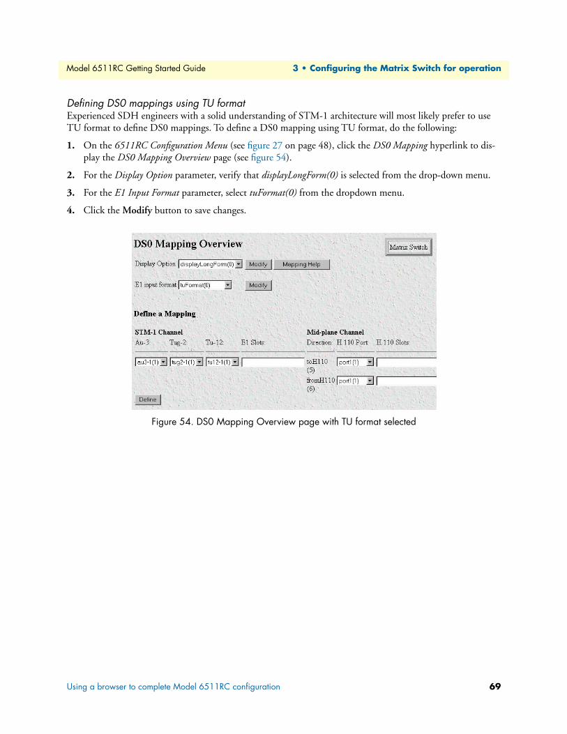
Model 6511RC Getting Started Guide 3 • Configuring the Matrix Switch for operation
Defining DS0 mappings using TU formatExperienced SDH engineers with a solid understanding of STM-1 architecture will most likely prefer to use TU format to define DS0 mappings. To define a DS0 mapping using TU format, do the following:
1. On the 6511RC Configuration Menu (see figure 27 on page 48), click the DS0 Mapping hyperlink to dis-play the DS0 Mapping Overview page (see figure 54).
2. For the Display Option parameter, verify that displayLongForm(0) is selected from the drop-down menu.
3. For the E1 Input Format parameter, select tuFormat(0) from the dropdown menu.
4. Click the Modify button to save changes.
Figure 54. DS0 Mapping Overview page with TU format selected
Using a browser to complete Model 6511RC configuration 69
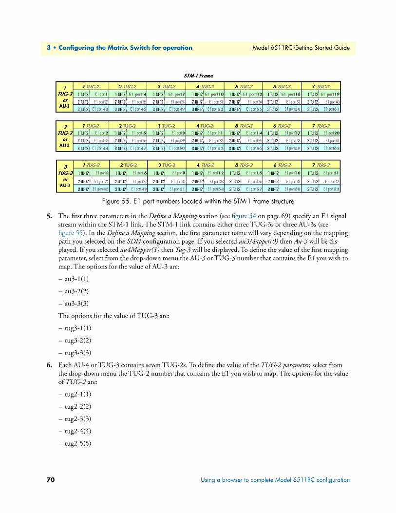
3 • Configuring the Matrix Switch for operation Model 6511RC Getting Started Guide
Figure 55. E1 port numbers located within the STM-1 frame structure
5. The first three parameters in the Define a Mapping section (see figure 54 on page 69) specify an E1 signal stream within the STM-1 link. The STM-1 link contains either three TUG-3s or three AU-3s (see figure 55). In the Define a Mapping section, the first parameter name will vary depending on the mapping path you selected on the SDH configuration page. If you selected au3Mapper(0) then Au-3 will be dis-played. If you selected au4Mapper(1) then Tug-3 will be displayed. To define the value of the first mapping parameter, select from the drop-down menu the AU-3 or TUG-3 number that contains the E1 you wish to map. The options for the value of AU-3 are:
– au3-1(1)
– au3-2(2)
– au3-3(3)
The options for the value of TUG-3 are:
– tug3-1(1)
– tug3-2(2)
– tug3-3(3)
6. Each AU-4 or TUG-3 contains seven TUG-2s. To define the value of the TUG-2 parameter, select from the drop-down menu the TUG-2 number that contains the E1 you wish to map. The options for the value of TUG-2 are:
– tug2-1(1)
– tug2-2(2)
– tug2-3(3)
– tug2-4(4)
– tug2-5(5)
70 Using a browser to complete Model 6511RC configuration

Model 6511RC Getting Started Guide 3 • Configuring the Matrix Switch for operation
– tug2-6(6)
– tug2-7(7)
7. Each TUG-2 contains three TU-12s (which in turn contain one E1 each). To define the value of the TU-12 parameter, select one of the following values from the drop-down menu:
– tu12-1(1)
– tu12-2(2)
– tu12-3(3)
8. The three parameters you defined above specify a selected E1 signal stream within the STM-1 link. For E1 Slots, enter the timeslot numbers within the selected E1 link that you wish to map to the H.110 bus.
When entering E1 and H.110 timeslot numbers you must define the same number of timeslots on the SDH and mid-plane sides of the mapping. The timeslots are defined by entering a text string that repre-sents the timeslot numbers.
The following notation should be used for assigning timeslots:
– dash: (-), e.g., 1–4
– comma: (,), e.g., 1,4,9
– combo: 1-2,3,6-7
At this point you have defined the SDH channel composed of a selected E1 signal stream and a set of timeslots within that E1. Now you must define the mid-plane channel to be correlated with the SDH channel.
9. Under the heading Mid-plane Channel, in the first row, labeled to H110(5), for H.110 number, select your desired H.110 port number from the drop-down menu.
10. In the first row, labeled toH110(5), for H.110 slots, enter the timeslot numbers you wish to map to the H.110 bus (from the E1).
11. In the second row, labeled fromH110(6), select your desired H.110 port number from the drop-down menu
12. In the second row, labeled fromH110(6), for H.110 slots, enter the timeslot numbers you wish to map from the H.110 bus (to the E1).
13. Click the Define button. The new mapping will appear at the bottom of the page in the Defined Mappings table.
14. Examine the Defined Mappings table to verify that the new mapping appears and was correctly entered and recorded.
Using a browser to complete Model 6511RC configuration 71
3 • Configuring the Matrix Switch for operation Model 6511RC Getting Started Guide
Examples for configuring DS0 mappings.
Three examples are provided:
• Example 1—For the E1 located in TUG-3 or AU-3 number 1, TUG-2 number 1, TU-12 number 1(Matrix Switch E1 port number 1):
- map all 32 timeslots of the received E1 signal to H.110 port 1 timeslots 1-32
- map all 32 timeslots of the transmitted E1 signal from H.110 port 1 timeslots 33-64
• Example 2—For the E1 located in TUG-3 or AU-3 number 2, TUG-2 number 1, TU-12 number 1(Matrix Switch E1 port number 2):
- map all 32 timeslots of the received E1 signal to H.110 port 1 timeslots 65-96
- map all 32 timeslots of the transmitted E1 signal from H.110 port 1 timeslots 97-128
• Example 3—For the E1 located in TUG-3 or AU-3 number 1, TUG-2 number 1, TU-12 number 3(Matrix Switch E1 port number 7)
- map all 32 timeslots of the E1 received signal to H.110 port 4 timeslots 1-32
- map all 32 timeslots of the E1 transmitted signal from H.110 port 4 timeslots 33-64
Example 1
Map TUG-3 or AU-3 no. 1, TUG-2 no. 1, TU-12 no. 1 received, timeslots 1-32 to H.110 Port 1 timeslots 1-32.
Map TUG-3 or AU-3 no. 1, TUG-2 no. 1, TU-12 no. 1 transmitted, timeslots 1-32 from H.110 Port 1 timeslots 33-64.
Solution:
1. For the value of the first parameter under SDH Channel, select TUG3-1(1) or AU3-1(1) from the drop-down menu.
2. For the value of TUG-2 select TUG2-1(1) from the drop-down menu.
3. For the value of TU-12 select TU12-1(1) from the drop-down menu.
4. For the value of E1 Slots, enter 1-32 in the text box.
5. For toH110(5), under H.110 Number, select port1(1) from the drop-down menu.
6. For toH110(5), under H.110 slots, enter 1-32 in the text box.
7. For fromH110(5), under H.110 Number, select port1(1) from the drop-down menu.
8. For fromH110(5), under H.110 slots, enter 33-64 in the text box.
9. Click the Define button.
10. Verify that your new mapping appears in the Defined Mappings table.
11. Examine the new mapping to ensure it was entered and recorded correctly.
You have completed the DS0 mapping procedure for example 1.
72 Using a browser to complete Model 6511RC configuration

Model 6511RC Getting Started Guide 3 • Configuring the Matrix Switch for operation
Example 2
Map TUG-3 or AU-3 no. 2, TUG-2 no. 1, TU-12 no. 1 received, timeslots 1-32 to H.110 Port 1 timeslots 65-96.
Map TUG-3 or AU-3 no. 1, TUG-2 no. 1, TU-12 no. 1 transmitted, timeslots 1-32 from H.110 Port 1 timeslots 97-128.
Solution:
1. For the value of the first parameter under SDH Channel, select either TUG3-2(2) or AU3-2(2) from the drop-down menu.
2. For the value of TUG-2 select TUG2-1(1) from the drop-down menu.
3. For the value of TU-12 select TU12-1(1) from the drop-down menu.
4. Under E1 Slots, enter 1-32 in the text box.
5. For toH110(5), under H.110 Number, select port1(1) from the drop-down menu.
6. For toH110(5), under H.110 slots, enter 65-96 in the text box.
7. For fromH110(5), under H.110 Number, select port1(1) from the drop-down menu.
8. For fromH110(5), under H.110 slots, enter 97-128 in the text box.
9. Click the Define button.
10. Verify your new mapping appears in the Defined Mappings table.
11. Examine the new mapping to ensure it was entered and recorded correctly.
You have completed the configuration for example 2.
Example 3
Map TUG-3 or AU-3 no. 1, TUG-2 no. 1, TU-12 no. 3 received, timeslots 1 - 32 to H.110 Port 4 timeslots 1-32.
Map TUG-3 or AU-3 no. 1, TUG-2 no. 1, TU-12 no. 3 transmitted, timeslots 1 - 32 from H.110 Port 4 timeslots 33- 64.
Solution:
1. For the value of the first parameter under SDH Channel, select either TUG3-1(1) or AU3-1(1) from the drop-down menu.
2. For the value of TUG-2 select TUG2-1(1) from the drop-down menu.
3. For the value of TU-12 select TU12-3(3) from the drop-down menu.
4. Under E1 Slots, enter 1-32 in the text box.
5. For toH110(5), under H.110 Number, select port4(4) from the drop-down menu.
6. For toH110(5), under H.110 slots, enter 1-32 in the text box.
7. For fromH110(5), under H.110 Number, select port4(4) from the drop-down menu.
8. For fromH110(5), under H.110 slots, enter 33-64 in the text box.
Using a browser to complete Model 6511RC configuration 73
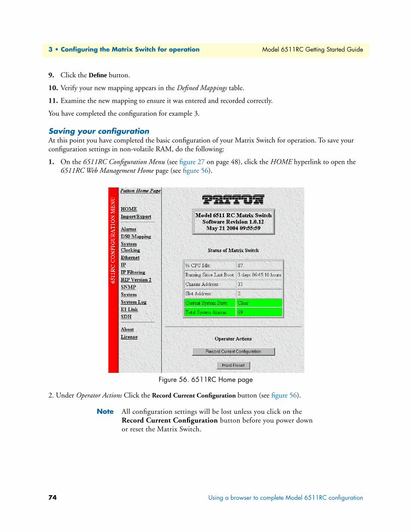
3 • Configuring the Matrix Switch for operation Model 6511RC Getting Started Guide
9. Click the Define button.
10. Verify your new mapping appears in the Defined Mappings table.
11. Examine the new mapping to ensure it was entered and recorded correctly.
You have completed the configuration for example 3.
Saving your configurationAt this point you have completed the basic configuration of your Matrix Switch for operation. To save your configuration settings in non-volatile RAM, do the following:
1. On the 6511RC Configuration Menu (see figure 27 on page 48), click the HOME hyperlink to open the 6511RC Web Management Home page (see figure 56).
Figure 56. 6511RC Home page
2. Under Operator Actions Click the Record Current Configuration button (see figure 56).
Note All configuration settings will be lost unless you click on the Record Current Configuration button before you power down or reset the Matrix Switch.
74 Using a browser to complete Model 6511RC configuration

Model 6511RC Getting Started Guide 3 • Configuring the Matrix Switch for operation
Backing up your configuration parametersThe 6511RC Matrix Switch provides Import/Export functions that enable you to back up (export) and restore (import) your Matrix Switch’s configuration parameters against possible failure. Should your Matrix Switch ever need replacing, a previously saved copy of your (exported) configuration file can quickly be loaded (imported) into a replacement Matrix Switch.
Note Import/Export functions require superuser access privileges.
Note The parameters that will be exported are the power-up settings as they are stored in flash memory and may not be the current operating parameters. To ensure that you export the most current parameters, go to HOME, then under Operator Actions, click on the Record Cur-rent Configuration button.
To import or export a configuration, do the following:
1. On the 6511RC Configuration Menu (see figure 27 on page 48), click the Import/Export hyperlink to dis-play the Import/Export page (see figure 57).
Figure 57. Import/Export page
Backing up your configuration parameters 75

3 • Configuring the Matrix Switch for operation Model 6511RC Getting Started Guide
Backing up the configuration store in flash memoryTo make a back-up copy of the configuration file currently stored in your Matrix Switch’s flash memory:
1. On the Import/Export page (see figure 57 on page 75) click the Export Flash... hyperlink. The Matrix Switch will get the configuration file currently stored in your Matrix Switch’s flash memory and display it in your browser (see figure 58)
Figure 58. Example Matrix Switch flash memory configuration file displayed in a browser
76 Backing up your configuration parameters

Model 6511RC Getting Started Guide 3 • Configuring the Matrix Switch for operation
2. To save the displayed data as a text file, use your browser’s Save function (see figure 59). Using Netscape or Internet Explorer, for example, do the following:
– Click the File menu.
– Click Save As. A dialog box will appear. Use the dialog to save the data displayed on your browser (your Matrix Switch configuration parameters) to a text file.
– Select the folder in which you want to store the file.
– Type a file name.
– Click Save.
Figure 59. Saving the access server flash memory configuration data as a text file
Completing the installationThis section verifies that the Model 6511RC is fully operational.
1. Perform a hard reset as follows:
– On the configuration menu, click the HOME hyperlink to display the Matrix Switch Home Page.
– Scroll down to Operator Actions buttons.
– Click the Hard Reset button.
2. Wait about ten seconds for the Matrix Switch to fully resume normal operation.
3. Verify the green POWER LED is lit. If the POWER LED is flashing green, refer to chapter 5, “Trouble-shooting and maintenance” on page 81.
4. Verify that green SYSTEM LED is flashing to indicate the Model 6511RC system is operating normally.
Completing the installation 77

3 • Configuring the Matrix Switch for operation Model 6511RC Getting Started Guide
5. Verify that the green WAN LED is illuminated, indicating that the Model 6511RCSTM-1 port is acti-vated, is synchronized with the SDH network, and operating normally.
Note If the Matrix Switch does not behave as described, the most likely cause is that the Matrix Switch SDH parameters values for the STM-1 link do not match those of the connected SDH network. To resolve this problem, double check the parameters on the Matrix Switch SDH Configuration page against those of the Connected SDH net-work, and correct any incorrect values.
6. There are three LEDs that indicate status for the Matrix Switch Ethernet subsystem. For information about interpreting the three Ethernet status LEDs, see table 3 on page 27.
Congratulations! Your Matrix Switch is now installed. If you require further information about configuring your Matrix Switch settings, refer to the Model 6511RC Matrix Switch Administrator’s Reference Guide included on your Model 6511RC CD-ROM.
Note For information on activating and de-activating your Model 6511RC Matrix Switch, refer to chapter 4, “Operation and shutdown” on page 79
78 Completing the installation

Chapter 4 Operation and shutdown
Chapter contentsIntroduction ..........................................................................................................................................................80Activating the Model 6511RC...............................................................................................................................80De-activating the Model 6511RC..........................................................................................................................80
79

4 • Operation and shutdown Model 6511RC Getting Started Guide
IntroductionThis chapter describes how to start up and power down the Model 6511RC.
Activating the Model 6511RCThe Model 6511RC is activated by completing the procedures in chapter 2, “Hardware installation” on page 31 and chapter 3, “Configuring the Matrix Switch for operation” on page 41. To activate the 6511RC, refer to the procedures in those chapters.
The Model 6511RC is designed for unattended operation. Once the Model 6511RC has been installed and configured, no further operator action is required under normal conditions.
De-activating the Model 6511RCPerform the following procedure to deactivate the Model 6511RC.
Note Be sure to wear an anti-static strap to prevent electrostatic damage to the blade.
1. Simultaneously press both red buttons on the front-panel handles of the 6511RC to unlock the handles and prepare the module for removal.
2. Simultaneously press both black handles outward and away from the center of the module to unseat the 6511RC from the mid-plane connectors.
3. Pull the handles to completely remove the Model 6511RC from the rack chassis. Place the module on an anti-static surface.
4. Repeat the above procedure to remove the rear module from the rack chassis. Place the blade on an anti-static surface.
80 Introduction
Chapter 5 Troubleshooting and maintenance
Chapter contentsIntroduction ..........................................................................................................................................................82Troubleshooting during initial deployment ...........................................................................................................82General fault analysis .............................................................................................................................................83Matrix Switch test tools .........................................................................................................................................86
Loopback test modes for the STM-1 port .......................................................................................................86Facility Loop [sonetFacilityLoop(1)] .........................................................................................................87Terminal loop [sonetTerminalLoop(2)] ....................................................................................................88Other Loop [sonetOtherLoop(3)] .............................................................................................................90
SDH section trace and path trace ....................................................................................................................90Sections and paths .....................................................................................................................................91Section trace ..............................................................................................................................................91Path trace ..................................................................................................................................................92Number of paths per frame .......................................................................................................................93
Periodic maintenance ............................................................................................................................................94Calibration ......................................................................................................................................................94
Maintenance..........................................................................................................................................................94Replacing the Model 6511RC .........................................................................................................................94
Exporting the current Model 6511RC configuration ................................................................................94Removing the defective Model 6511RC ....................................................................................................97Installing the replacement Model 6511RC ................................................................................................98Importing a saved configuration ................................................................................................................98Completing the installation .......................................................................................................................99
81

5 • Troubleshooting and maintenance Model 6511RC Getting Started Guide
IntroductionThis chapter provides guidance to assist you when performing troubleshooting and fault analysis as a Matrix Switch operator. Should you require more information or technical assistance, refer to chapter 6, “Contacting Patton for assistance” on page 101.
Troubleshooting during initial deploymentThe following table (see table 5) describes the symptoms for system faults that commonly occur when the Matrix Switch is first deployed, along with suggested remedies for each fault.
Note The symptoms listed in table 5 apply to single-fault scenarios involv-ing the Model 6511RC. Performing the recommended corrective action will solve such single points of failure, but may not correct any additional faults that might co-exist. If you are unable to correct a failure in your Matrix Switch, refer to chapter 6, “Contacting Patton for assistance” on page 101.
Note When removing the 6511RC from the chassis, follow the procedures cited in section “De-activating the Model 6511RC” on page 80.
Note When re-inserting the 6511RC into the chassis, please follow the pro-cedures cited in chapter 2, “Hardware installation” on page 31
Table 5. Symptoms
Problem Corrective Action
POWER LED (green)is extinguished
To verify that power is being supplied to the Model 6511RC via the CPCI chassis power bus: verify that at least one chassis power supply module is installed in the chassis and functioning normally.
POWER LED (green) is flashing
The 6511RC has detected a power failure on a power bus. There may be a prob-lem with the CPCI chassis power system which feeds the Model 6511RC such as a failed power supply module in the chassis. The Model 6511RC will function nor-mally with one power supply. Inspect the power supplies in the CPCI chassis to identify and replace the failed power supply module. If no failed power supply is found, or if the POWER LED continues flashing, contact Patton Technical Support to determine if the Matrix Switch should be replaced.
CPU FAIL LED (red) is lit CPU is unable to load the software from FLASH to RAM for operation. As soon as possible, remove the Model 6511RC from the CPCI chassis, wait 30 seconds, then re-insert the Model 6511RC into the CPCI chassis and see if the problem disap-pears. If the CPU FAIL LED remains lit after the Model 6511RC completes the power-up cycle, contact Patton Technical Support to determine if the Matrix Switch needs to be replaced.
ALARM LED (yellow) is lit or flashing
Indicates The 6511RC has detected a minor or major alarm condition. Examine the Alarm System Overview web management page to determine exactly which alarm(s) is(are) active.
82 Introduction

Model 6511RC Getting Started Guide 5 • Troubleshooting and maintenance
PO
General fault analysisThe following procedures outline steps you should follow when troubleshooting a Model 6511RC malfunction.
1. If possible, talk to the person who reported the problem and obtain a detailed description of the symp-toms. Create a written trouble report listing all the symptoms observed, including a complete description of the status for each LED indicator.
2. LED Status Indications and Recommended actions, table 6 provides information on interpreting LED status indicators along with recommended actions in response to each LED status indication. To correct the problem with your Matrix Switch, compare each LED status in your trouble report with the information in the table, and follow the recommend action for each LED.
SYSTEM LED (green) is not flashing
The Model 6511RC is not functioning properly. As soon as possible, force a module power cycle as follows: 1)Wearing an antistatic strap, simultaneously press both red buttons on the front-panel handles of the 6511RC to unlock the handles and prepare the module for removal. 2)Simultaneously press both black handles outward and away from the center of the module to unseat the 6511RC from the mid-plane connectors. 3) Wait 10 seconds. 4)Holding the module by the two black handles, very carefully push the module gently and firmly into the chassis until it is reseated against the midplane. 5)Press the black handle so that they click and lock closed. Once the Matrix Switch has resumed operation re-inspect the SYSTEM LED. If the SYSTEM LED does not begin flashing after completing the power-up cycle, contact Patton Technical Support to determine if the Matrix Switch should be replaced.
Table 6. LED status indications and recommended actions
LED Location Color Status Meaning
WER Front panel
Green On solid Power is being applied. No action recommended.Flashing The 6511RC has detected a power failure on a power bus. There may
be a problem with the CPCI power supply system such as a failed powersupply module in the chassis. The Model 6511RC will function normallywith one power supply. Inspect the power supplies in the CPCI chassis to identify and replace thefailed power supply module. If the POWER LED continues flashing whenall chassis power supplies are functional, contact Patton Technical Sup-port to determine if the Matrix Switch should be replaced.
Off No input power is being applied. Verify that at least one chassis powersupply module is installed in the chassis and functioning normally.
Table 5. Symptoms (Continued)
Problem Corrective Action
General fault analysis 83

5 • Troubleshooting and maintenance Model 6511RC Getting Started Guide
C
A
S
EE
-
CS
PU FAIL Front panel
Red On solid CPU is unable to load the software from FLASH to RAM for operation.As soon as possible, remove the Model 6511RC from the CPCI chassis,wait 30 seconds, then re-insert the Model 6511RC into the CPCI chassisand see if the problem disappears.If the CPU FAIL LED remains lit after the Model 6511RC completes the power-up cycle, contact Patton Technical Support to determine if the Matrix Switch needs to be replaced.
Off The CPU is operating normally. No action recommended.LARM Front
panelRed On solid A minor alarm condition has been detected.
Flashing A major alarm condition has been detected.Off The Model 6511RC is operating normally. No action recommended.
YSTEM Front panel
Green Flashing The Model 6511RC is operating normally. No action recommended.Offor
On solid
The Model 6511RC is not functioning properly. As soon as possible, remove the Model 6511RC from the CPCI chassis,wait 10 seconds, then re-insert the Model 6511RC into the CPCI chassisand see if the problem disappears.Once the Matrix Switch has resumed operation re-inspect the SYSTEM LED. If the SYSTEM LED does not begin flashing after completing the power-up cycle, contact Patton Technical Support to determine if the Matrix Switch should be replaced.
NET(NOD)
Front panel
Green Flash-ing or
On solid
Indicates there is Ethernet frame activity on one or more of the 6511RC’sEthernet interfaces, including the two rear-panel 10/100/1000 ports, the front -panel 10/100 port, and the packet--switched PICMG 2.16 bus. No action recommended
Off • Indicates NO Ethernet frame activity detected on any of the 6511RC’s Ethernet interfaces, including the PICMG 2.16 bus.
• Verify that an Ethernet cable is plugged into the hub, switch, or workstation and the 10/100 Ethernet port on the front panel of the Model6511RC.
• Verify that the hub, switch, or workstation is powered on.
• Verify that the correct straight-through or cross-over cable is being used, depending on whether you are connecting to a workstation (PC), hub, or switch.
• Replace the cable. If the problem still exists, contact Patton TechnicalSupport to determine if the Matrix Switch should be replaced.
LK OURCE
Front panel
Green On solid The 6511RC is set as the Master Clock source. No action recommended.
Flashing The 6511RC is set as the secondary clock source. No action recommended.
Off The 6511RC is set as the slave, getting its clock from the H.110 Bus. No action recommended.
Table 6. LED status indications and recommended actions (Continued)
LED Location Color Status Meaning
84 General fault analysis
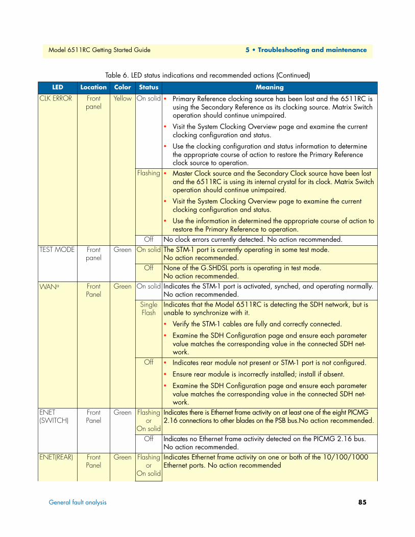
Model 6511RC Getting Started Guide 5 • Troubleshooting and maintenance
C
TE
W
E(S
E
LK ERROR Front panel
Yellow On solid • Primary Reference clocking source has been lost and the 6511RC is using the Secondary Reference as its clocking source. Matrix Switch operation should continue unimpaired.
• Visit the System Clocking Overview page and examine the current clocking configuration and status.
• Use the clocking configuration and status information to determine the appropriate course of action to restore the Primary Reference clock source to operation.
Flashing • Master Clock source and the Secondary Clock source have been lost and the 6511RC is using its internal crystal for its clock. Matrix Switchoperation should continue unimpaired.
• Visit the System Clocking Overview page to examine the current clocking configuration and status.
• Use the information in determined the appropriate course of action torestore the Primary Reference to operation.
Off No clock errors currently detected. No action recommended.ST MODE Front
panelGreen On solid The STM-1 port is currently operating in some test mode.
No action recommended.Off None of the G.SHDSL ports is operating in test mode.
No action recommended.ANa Front
PanelGreen On solid Indicates the STM-1 port is activated, synched, and operating normally.
No action recommended.Single Flash
Indicates that the Model 6511RC is detecting the SDH network, but is unable to synchronize with it.
• Verify the STM-1 cables are fully and correctly connected.
• Examine the SDH Configuration page and ensure each parameter value matches the corresponding value in the connected SDH net-work.
Off • Indicates rear module not present or STM-1 port is not configured.
• Ensure rear module is incorrectly installed; install if absent.
• Examine the SDH Configuration page and ensure each parameter value matches the corresponding value in the connected SDH net-work.
NETWITCH)
Front Panel
Green Flashingor
On solid
Indicates there is Ethernet frame activity on at least one of the eight PICMG 2.16 connections to other blades on the PSB bus.No action recommended.
Off Indicates no Ethernet frame activity detected on the PICMG 2.16 bus.No action recommended.
NET(REAR) Front Panel
Green Flashingor
On solid
Indicates Ethernet frame activity on one or both of the 10/100/1000 Ethernet ports. No action recommended
Table 6. LED status indications and recommended actions (Continued)
LED Location Color Status Meaning
General fault analysis 85

5 • Troubleshooting and maintenance Model 6511RC Getting Started Guide
R
A
R
O
1EInLE4toR
Matrix Switch test toolsFor the purpose of testing and troubleshooting the STM-1 link, the DS0 Mapping definitions, and H.110 bus connectivity, the Model 6511RC Matrix Switch offers the following tool sets:
• Loopback test modes for the Matrix Switch STM-1 port
• SDH Section Trace and SDH Path Trace functions for the STM-1 link
The following sections describe these tool sets in detail.
Loopback test modes for the STM-1 portThe Matrix Switch provides the following diagnostic loopback test modes for the STM-1 port:
• SDH facility loop (see section “Facility Loop [sonetFacilityLoop(1)]” on page 87)
• SDH terminal loop (see section “Terminal loop [sonetTerminalLoop(2)]” on page 88)
• H.110 loop (see section “Other Loop [sonetOtherLoop(3)]” on page 90)
The facility and terminal loops are specified by the SDH protocol. The H.110 loop is proprietary to the Fore-Front Matrix Switch, and fulfills the SDH specification for a third vendor-defined loop.
Off There is NO Ethernet frame activity on either of the 10/100/1000 Ethernet ports. No action recommended
EADY Front panel
Blue On Indicates module is ready for removal from cPCI chassis.Off Indicates module NOT ready for removal from cPCI chassis.
Do not remove card from chassis.LARM Rear
bladeYellow On solid A minor alarm condition has been detected.
Flashing A major alarm condition has been detected.Off The Model 6511RC is operating normally. No action recommended.
EADY Rear blade
Blue On Card ready for removal from cPCI chassis.Off Card not ready for removal from cPCI chassis.
Do not remove card from chassis.N LINE On Reserved for future use
Off Reserved for future use0/100 NET
Front Panel
Green On Ethernet Link is established
tegrated Ds on RJ-5 connec-r
Off No Ethernet link is establishedYellow On Flashes to indicates Ethernet frame activity on this port
Off Indicates no Ethernet frame activity on this port
EADY Blue On Card ready for removal from cPCI chassis.Off Card not ready for removal from cPCI chassis.
a. This LED provides status indications for the STM-1 WAN link established via the optical or electrical ports on the Rear Module of the 6511RC
Table 6. LED status indications and recommended actions (Continued)
LED Location Color Status Meaning
86 Matrix Switch test tools

Model 6511RC Getting Started Guide 5 • Troubleshooting and maintenance
To understand how these test modes work, you must first understand the basic architecture of the Model 6511RC’s TDM mapping functions. The TDM mapping function provides the connection between the STM-1 port and the H.110 bus. Within the TDM mapper (see figure 60) data passes between the SDH framing pro-cessor and the H.110 framing processor.
Figure 60. Matrix Switch TDM mapping architecture
The various loopback test modes route data through one or both of these framing processors, with the data path making a U-turn in one framer or the other. Subsequent paragraphs describe the details of each loopback test mode for the STM-1 port.
Facility Loop [sonetFacilityLoop(1)]You can use the facility loop to test and troubleshoot the operation of the STM-1 link, including the Matrix Switch’s STM-1 port and the fiber-optic or coaxial cables connected to it.
The facility loop (see figure 61) returns data received from the SDH facility (the STM-1 link) back to the same SDH facility. In other words, when the Facility Loop is activated, the Matrix Switch receives data from the STM-1 link and transmits the (unmodified) data back to the STM-1 link.
The U-turn for the facility loop occurs within the SDH framer on the Matrix Switch. The data path for the facility loop traverses the SDH framer, but not the H.110 framer. Data enters the Matrix Switch at the STM-1 receive port, and enters the SDH framer where it loops back toward the STM-1 link, leaving the Matrix switch at the STM-1 transmit port.
Figure 61. Facility Loopback test mode
To activate the facility loopback test mode:
1. On the configuration menu, click the SDH hyperlink to display the SDH Overview page.
TDM Mapper
H.110 bus STM-1 port
Model 6511RC Matrix Switch
Rx
Tx
Tx
Rx
H.110Framer
SDHFramer
Matrix Switch test tools 87

5 • Troubleshooting and maintenance Model 6511RC Getting Started Guide
2. At the top of the SDH Overview page, click the Configuration hyperlink to display the SDH Configuration page (see figure 62).
Figure 62. SDH Configuration page with sonetFacilityLoop(1) selected
3. Scroll down to the Loopback parameter in the SDH Interface Configuration table.
4. From the drop-down menu, select sonet(facilityLoop(1).
5. Click the first Submit button located just below the SDH Interface Parameters table.
To deactivate the Facility Loopback test mode, from the LoopBack parameter drop-down menu, select sonet-NoLoop(0) and click the Submit button.
Terminal loop [sonetTerminalLoop(2)]The terminal loop (see figure 63) returns data received from the SDH terminals back to those SDH terminals (other ForeFront modules on the same H.110 bus). In other words, when the Terminal Loop is activated, the Matrix Switch receives data from other ForeFront modules via the H.110 bus and transmits the (unmodified) data back to those same modules (via the H.110 bus).
The U-turn for the terminal loop occurs within the SDH framer on the Matrix Switch. The data path for the terminal loop traverses both the H.110 framer and the SDH framer. Data transmitted by the SDH terminals (other ForeFront modules) enters the Matrix Switch from the H.110 bus through the mid-plane
Figure 63. Terminal loopback test mode
88 Matrix Switch test tools

Model 6511RC Getting Started Guide 5 • Troubleshooting and maintenance
connections. The data passes through the H.110 framer, then traverses the SDH framer where it loops back, passing through the H.110 framer again. The data leaves the Matrix switch through its mid-plane connections and returns via the H.110 bus to the sending SDH terminals (other ForeFront modules).
The terminal loop affects only those DS0s that are mapped from the H.110 bus to the STM-1 link or from the STM-1 link to the H.110 bus. Likewise, the loop affects only those ForeFront modules included in one or more such DS0 mappings.
The terminal loop exercises the physical and logical connections between the Matrix Switch and the other ForeFront modules connected to the same H.110 bus (its SDH terminals). You can use the terminal loop to test and troubleshoot the DS0 mappings you have defined while simultaneously testing H.110 bus connectiv-ity with other ForeFront modules via the chassis mid-plane.
To activate the Terminal Loop test mode:
1. On the configuration menu, click the SDH hyperlink to display the SDH Overview page.
2. At the top of the SDH Overview page, click the Configuration hyperlink to display the SDH Configuration page (see figure 64).
3. Scroll down to the Loopback parameter in the SDH Interface Configuration table.
4. From the drop-down menu, select sonetTerminalLoop(2).
5. Click the first Submit button located just below the SDH Interface Parameters table.
Figure 64. SDH Configuration page with sonetTerminalLoop(2) selected
To deactivate the terminal loop test mode, from the LoopBack parameter drop-down menu, select sonet-NoLoop(0) and click the Submit button.
Matrix Switch test tools 89

5 • Troubleshooting and maintenance Model 6511RC Getting Started Guide
Other Loop [sonetOtherLoop(3)]The other loop [sonetOtherLoop(3)] operates much like the facility loop, however the data enters the H.110 framer where it makes a U-turn. The Other Loop test mode (See figure 65) is a factory debugging and hardware test tool intended for use by Patton engineering. The terminal loop and facility loop provide all the functional-ity a Matrix Switch operator should require. Though it is available to Matrix Switch operators, the Other Loop test mode offers no further advantage for testing or troubleshooting in the field.
Figure 65. Other Loopback test mode
SDH section trace and path traceThe Matrix Switch supports the section trace and path trace functions specified in the SDH protocol. You can use these trace functions to verify connectivity across an SDH circuit or circuit segment and to validate the link is operating properly. When a trace is enabled, two SDH devices pass a trace message to each other across an SDH link or link segment. When the message arrives without errors the trace succeeds, indicating the connec-tion is healthy. If a device receives a trace message that does not match the expected value, a trace mismatch occurs, indicating an error in the connection.
Note The trace function must be enabled and configured identically in both the Matrix Switch and the connected SDH network in order for the trace to operate.
90 Matrix Switch test tools

Model 6511RC Getting Started Guide 5 • Troubleshooting and maintenance
Sections and pathsBetween a pair of SDH multiplexers, an SDH circuit may comprise multiple cable segments connected by intermediate devices such as signal repeaters and add-drop multiplexers (see figure 66). A cable segment with a regenerator at one or both endpoints is called a section. A set of cable segments with an add-drop multiplexer at one or both endpoints is called a line. An SDH circuit with full-service multiplexers at both endpoints is called a path.
Figure 66. Section, path, and line within an SDH circuit
Section traceThe section trace function verifies section connectivity between the two section-terminating nodes.Two SDH section-terminating devices perform the section trace over the STM-1 media segment between them. When section trace is enabled, the SDH frame carries a trace message in either the J0 byte or the section trace string. The value you define for Section Trace Message Length determines which field will carry the Section Trace Mes-sage, as specified below:
• 1-byte section trace message length—Use the J0 byte for trace messaging, and ignore the contents of sec-tion trace string. The value of J0 may be any positive integer in the range of 0 to 255.
• 16-byte section trace message length—Use the section trace string for section trace messaging, and ignore the contents of J0. The value of section trace string may be any alphanumeric text string up to 15 characters long. The 16-byte field includes CRC-7 in the 16th byte.
• 64-byte section trace message length—Use the section trace string for section trace messaging, and ignore the contents of J0. The value of section trace string may be any alphanumeric text string up to 64 characters long. The 64-byte section trace string does not include any CRC.
To enable section trace:
1. On the configuration menu, click the SDH hyperlink to display the SDH Overview page.
2. At the top of the SDH Overview page, click the Configuration hyperlink to display the SDH Configuration page (see figure 67).
Matrix Switch test tools 91
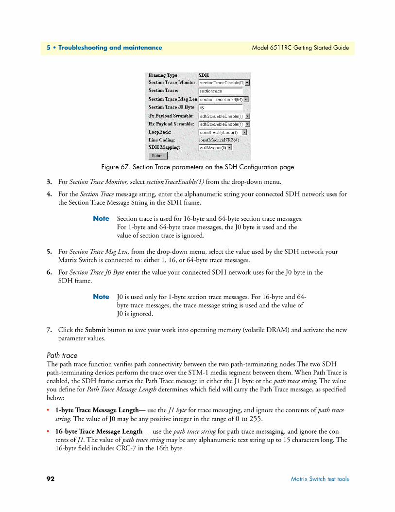
5 • Troubleshooting and maintenance Model 6511RC Getting Started Guide
Figure 67. Section Trace parameters on the SDH Configuration page
3. For Section Trace Monitor, select sectionTraceEnable(1) from the drop-down menu.
4. For the Section Trace message string, enter the alphanumeric string your connected SDH network uses for the Section Trace Message String in the SDH frame.
Note Section trace is used for 16-byte and 64-byte section trace messages. For 1-byte and 64-byte trace messages, the J0 byte is used and the value of section trace is ignored.
5. For Section Trace Msg Len, from the drop-down menu, select the value used by the SDH network your Matrix Switch is connected to: either 1, 16, or 64-byte trace messages.
6. For Section Trace J0 Byte enter the value your connected SDH network uses for the J0 byte in the SDH frame.
Note J0 is used only for 1-byte section trace messages. For 16-byte and 64-byte trace messages, the trace message string is used and the value of J0 is ignored.
7. Click the Submit button to save your work into operating memory (volatile DRAM) and activate the new parameter values.
Path traceThe path trace function verifies path connectivity between the two path-terminating nodes.The two SDH path-terminating devices perform the trace over the STM-1 media segment between them. When Path Trace is enabled, the SDH frame carries the Path Trace message in either the J1 byte or the path trace string. The value you define for Path Trace Message Length determines which field will carry the Path Trace message, as specified below:
• 1-byte Trace Message Length— use the J1 byte for trace messaging, and ignore the contents of path trace string. The value of J0 may be any positive integer in the range of 0 to 255.
• 16-byte Trace Message Length — use the path trace string for path trace messaging, and ignore the con-tents of J1. The value of path trace string may be any alphanumeric text string up to 15 characters long. The 16-byte field includes CRC-7 in the 16th byte.
92 Matrix Switch test tools

Model 6511RC Getting Started Guide 5 • Troubleshooting and maintenance
• 64-byte Trace Message Length — use the section trace string for section trace messaging, and ignore the contents of J1. The value of section trace string may be any alphanumeric text string up to 64 characters long. The 64-byte field does not include any CRC.
Number of paths per frameThe STM-1 frame can support one path or three paths, depending on how the STM-1 signal is mapped.
• AU-4 mapping—Using AU-4 mapping the STM-1 frame supports a single path. When you select AU-4 mapping for the value of the SDH Mapping parameter, the Matrix Switch displays only the Path-1 Trace parameters.
• AU-3 mapping—Using AU-3 mapping the STM-1 frame supports three paths. Each of the three AU-3s in the STM-1 frame represents a separate path. When you select AU-3 mapping for the value of the SDH Map-ping parameter, the Matrix Switch displays the path trace parameters for each of the three paths. Path-1, Path-2, and Path-3 (one path trace for each AU-3 in the STM-1 frame).
To enable path trace:
1. On the configuration menu, click the SDH hyperlink to display the SDH Overview page.
2. At the top of the SDH Overview page, click the Configuration hyperlink to display the SDH Configuration page (see figure 68).
Figure 68. Path Trace parameters on the SDH Configuration page
3. In the SDH Trace Parameters table, for Path-1 Trace Monitor, select pathTraceEnable(1) from the drop-down menu.
4. For Path-1 Trace message string, enter the alphanumeric string your connected SDH network uses for the path-1 trace message in the text box.
Matrix Switch test tools 93
5 • Troubleshooting and maintenance Model 6511RC Getting Started Guide
Note Path-1 trace message is used for 16-byte and 64-byte path-1 trace messages. For 1-byte and 64-byte trace messages, the J1 byte is used and the value of path-1trace message is ignored.
5. For Path-1 Trace Msg Len, select the value corresponding to the trace message length your connected SDH network uses.
6. For Path-1 Trace J1 Byte, enter the value your connected SDH network uses for the J1 byte in the SDH frame.
Note J1 is used only for 1-byte path trace messages. For 16-byte and 64-byte trace messages, the trace message string is used and the value of J1 is ignored.
7. For Path-1 Signal Label, enter the value your connected SDH network uses for the path-1 signal label in the SDH frame.
8. If you have selected AU-3 mapping, repeat steps 3 through 7 to define values for the Path-2 and Path-3 trace parameters.
9. Click the Submit button to save your work into operating memory (volatile DRAM) and activate the new parameter values.
Periodic maintenanceConsult the rack chassis user manual for information on preventative maintenance (such as cleaning the chassis air cooling vents to remove accumulated dust).
CalibrationThe Model 6511RC requires no calibration.
MaintenanceThis section describes replacing the Model 6511RC.
Replacing the Model 6511RCIf you isolate a problem to the a Model 6511RC component, the entire Model 6511RC must be replaced as described in the follow section.
Exporting the current Model 6511RC configurationThe 6511RC Matrix Switch provides Import/Export functions. These functions enable you to back up (export) and restore (import) your Matrix Switch’s configuration parameters against possible failure. Should your Matrix Switch ever need replacing, a previously saved copy of your (exported) configuration file can quickly be loaded (imported) into a replacement Matrix Switch.
Note Import/Export functions require superuser access privileges.
94 Periodic maintenance

Model 6511RC Getting Started Guide 5 • Troubleshooting and maintenance
Note The parameters that will be exported are the power-up settings as they are stored in flash memory and may not be the current operating parameters. To ensure that you export the most current parameters, go to HOME, then under Operator Actions, click on the Record Current Configuration button.
1. If you already have an exported backup copy of your current configuration, go to “Removing the defective Model 6511RC” on page 97. Otherwise, go to step 2.
2. On the Configuration Menu pane, click the Import/Export hyperlink to display the Import/Export page (figure 69).
Figure 69. Import/Export page
Maintenance 95

5 • Troubleshooting and maintenance Model 6511RC Getting Started Guide
3. To make a back-up copy of the configuration file currently stored in your Matrix Switch’s flash memory:
– On the Import/Export page (figure 69 on page 95) click the Export Flash... hyperlink. The Matrix Switch will get the configuration file currently stored in your Matrix Switch’s flash memory and display it in your browser (figure 70)
Figure 70. Example Matrix Switch flash memory configuration file displayed in a browser
96 Maintenance

Model 6511RC Getting Started Guide 5 • Troubleshooting and maintenance
– To save the displayed data as a text file, use your browser’s Save function (see figure 71). Using Netscape or Internet Explorer, for example.
• Click the File menu.
• Click Save As. A dialog box will appear. Use the dialog to save the data displayed on your browser (your Matrix Switch configuration parameters) to a text file.
• Select the folder in which you want to store the file,
• Type a file name.
• Click Save.
Figure 71. Saving the access server flash memory configuration data as a text file
Removing the defective Model 6511RC1. Remove the replacement Model 6511RC from its shipping container and place it near the chassis in which
the malfunctioning Model 6511RC is located.
Note The Model 6511RC Matrix Switch modules are hot-swap-able, so it is not necessary to deactivate the rack chassis before replacing a module.
2. Disconnect and label the following cables from the malfunctioning Model 6511RC:
– The STM-1 WAN cable
– The RS-232 CONFIG cable (if installed)
– The 10/100 Ethernet cable (if installed)
– The two 10/100/1000 Ethernet cables (if installed)
Maintenance 97
5 • Troubleshooting and maintenance Model 6511RC Getting Started Guide
Note Be sure to wear an anti-static strap to prevent electrostatic damage to the module.
3. Simultaneously press both red buttons on the front-panel handles of the 6511RC to unlock the handles and prepare the module for removal.
4. Simultaneously press both black handles outward and away from the center of the module to unseat the 6511RC from the mid-plane connectors.
5. Pull the handles gently and firmly to completely remove the Model 6511RC from the rack chassis. Place the module on an anti-static surface.
6. Repeat the above procedure to remove the rear module from the rack chassis. Place the rear module on an anti-static surface.
7. Place the removed modules in the container the replacement Model 6511RC came in so you can return the defective Model 6511RC for repair.
Installing the replacement Model 6511RC1. Insert the replacement Model 6511RC into the rack chassis.
2. Insert the rear blade into the desired slot in the rack chassis. Make sure the blade is seated properly in the slot guides.
3. Gently press the blade into the chassis until the alignment/ESD pin engages the chassis. When the blade is fully seated, the red buttons in the handles click up automatically, thus locking the handle and activating the switch (closed position). The click of the button gives a visual and audible confirmation that the board is fully seated.
4. Connect the following cables to the Model 6511RC:
– The STM-1 WAN cable
– The RS-232 CONFIG cable
– The 10/100 Ethernet cable
– The two 10/100/1000 Ethernet cables (if used)
5. Verify that the green POWER LED is lit.
Importing a saved configurationBefore importing a saved configuration, you must define the Model 6511RC’s IP address and netmask. These parameters are defined via the Model 6511RC RS-232 CONFIG port on the Model 6511RC.
1. Refer to chapter 3, “Configuring the Matrix Switch for operation” on page 41 and follow the procedures contained in section “Initial configuration through the RS-232 control port” on page 43.
2. To import a saved configuration, connect your Web browser to the Administration Pages, then click on Import/Export under the Configuration Menu to display the Import/Export page (figure 69 on page 95).
3. To import a configuration file into the Model 6511RC, type the complete path and filename for the con-figuration file you wish to load or click on the Browse… button to select the desired file, then click the Submit Query button.
98 Maintenance

Model 6511RC Getting Started Guide 5 • Troubleshooting and maintenance
Upon successfully importing the file, the Model 6511RC will display Configuration Load Complete, indi-cating that the new operating parameters have been loaded into flash memory.
4. On the Configuration Menu, click the HOME hyperlink, then click the Hard Reset button under Opera-tor Actions.
Note Do not select Record Current Configuration after importing con-figuration parameters.
Completing the installationThis section verifies that the Model 6511RC is fully operational.
1. Verify that the green POWER LED is lit. If the POWER LED is flashing green, refer to Chapter 5, “Trou-bleshooting and maintenance”.
2. Verify that the WAN LED illuminates, indicating that the Model 6511RC is synchronizing with the T1/E1 signal.
3. Verify that after 5 seconds, the WAN LED begins flashing, indicating that the Model 6511RC is satisfied with the quality of the T1/E1 signal.
4. Verify that after 10 seconds, the WAN LED extinguishes, indicating that the Model 6511RC is satisfied with the network signal and that the link is ready for use.
5. Verify that the green Ethernet LED is either flashing (indicating link status is nominal for the front Ether-net port) or on solid (indicating that link status is nominal for at least one of the Ethernet backplane con-nections).
The Model 6511RC is operational.
Maintenance 99

5 • Troubleshooting and maintenance Model 6511RC Getting Started Guide
100 Maintenance
Chapter 6 Contacting Patton for assistance
Chapter contentsIntroduction ........................................................................................................................................................102Contact information............................................................................................................................................102Warranty Service and Returned Merchandise Authorizations (RMAs).................................................................102
Warranty coverage ........................................................................................................................................102Out-of-warranty service ...........................................................................................................................102Returns for credit ....................................................................................................................................102Return for credit policy ...........................................................................................................................103
RMA numbers ..............................................................................................................................................103Shipping instructions ..............................................................................................................................103
101

6 • Contacting Patton for assistance Model 6511RC Getting Started Guide
IntroductionThis chapter contains the following information:
• “Contact information”—describes how to contact PATTON technical support for assistance.
• “Warranty Service and Returned Merchandise Authorizations (RMAs)”—contains information about the RAS warranty and obtaining a return merchandise authorization (RMA).
Contact informationPatton Electronics offers a wide array of free technical services. If you have questions about any of our other products we recommend you begin your search for answers by using our technical knowledge base. Here, we have gathered together many of the more commonly asked questions and compiled them into a searchable database to help you quickly solve your problems.
• Online support—available at www.patton.com.
• E-mail support—e-mail sent to [email protected] will be answered within 1 business day
• Telephone support—standard telephone support is available Monday through Friday, from 8:00 A.M. to 5:00 P.M. EST (8:00 to 17:00 UTC-5), Monday through Friday by calling +1 (301) 975-1007
Warranty Service and Returned Merchandise Authorizations (RMAs)Patton Electronics is an ISO-9001 certified manufacturer and our products are carefully tested before ship-ment. All of our products are backed by a comprehensive warranty program.
Note If you purchased your equipment from a Patton Electronics reseller, ask your reseller how you should proceed with warranty service. It is often more convenient for you to work with your local reseller to obtain a replacement. Patton services our products no matter how you acquired them.
Warranty coverageOur products are under warranty to be free from defects, and we will, at our option, repair or replace the prod-uct should it fail within one year from the first date of shipment. Our warranty is limited to defects in work-manship or materials, and does not cover customer damage, lightning or power surge damage, abuse, or unauthorized modification.
Out-of-warranty servicePatton services what we sell, no matter how you acquired it, including malfunctioning products that are no longer under warranty. Our products have a flat fee for repairs. Units damaged by lightning or elephants may require replacement.
Returns for creditCustomer satisfaction is important to us, therefore any product may be returned with authorization within 30 days from the shipment date for a full credit of the purchase price. If you have ordered the wrong equipment or you are dissatisfied in any way, please contact us to request an RMA number to accept your return. Patton is not responsible for equipment returned without a Return Authorization.
102 Introduction

Model 6511RC Getting Started Guide 6 • Contacting Patton for assistance
Return for credit policy • Less than 30 days: No Charge. Your credit will be issued upon receipt and inspection of the equipment.
• 30 to 120 days: We will add a 20% restocking charge (crediting your account with 80% of the purchase price).
• Over 120 days: Products will be accepted for repairs only.
RMA numbersRMA numbers are required for all product returns. You can obtain an RMA by doing one of the following:
• Completing a request on the RMA Request page in the Support section at www.patton.com
• By calling +1 (301) 975-1000 and speaking to a Technical Support Engineer
• By sending an e-mail to [email protected]
All returned units must have the RMA number clearly visible on the outside of the shipping container. Please use the original packing material that the device came in or pack the unit securely to avoid damage during shipping.
Shipping instructionsThe RMA number should be clearly visible on the address label. Our shipping address is as follows:
Patton Electronics CompanyRMA#: xxxx7622 Rickenbacker Dr.Gaithersburg, MD 20879-4773 USA
Patton will ship the equipment back to you in the same manner you ship it to us. Patton will pay the return shipping costs.
Warranty Service and Returned Merchandise Authorizations (RMAs) 103

6 • Contacting Patton for assistance Model 6511RC Getting Started Guide
104 Warranty Service and Returned Merchandise Authorizations (RMAs)