model 55, 75, 90, & hr - hog slat€¦ · hog slat inc. newton grove, nc usa april 2018...
TRANSCRIPT
Hog Slat Inc. Newton Grove, NC USA April 2018
Grow-FlexTM Feed System
MODEL 55, 75, 90, & HR
Installation & Operator’s Manual Warranty • Installation • Operation
Parts List • Maintenance

Hog Slat Inc. Newton Grove, NC USA April 2018 2
Grow- FlexTM Feed System
This page is intentionally left blank.

Hog Slat Inc. Newton Grove, NC USA April 2018 3
Grow- FlexTM Feed System
Table of Contents
WARRANTY INFORMATION ............................................................................................................................................................4
SAFETY INFORMATION ..................................................................................................................................................................5
SELECTING THE SYSTEM ..............................................................................................................................................................6
SYSTEM COMPARISON CHART, SYSTEM LENGTH SPECIFICATIONS ......................................................................................7
PLANNING THE GROW-FLEX SYSTEM .........................................................................................................................................8
TYPICAL SYSTEM INSTALLATIONS - RECOMMENDED & NOT RECOMMENDED LAYOUTS ................................................. 10
BIN TO BUILDING PLACEMENT CHART ...................................................................................................................................... 12
INSTALLATION INSTRUCTIONS FOR THE GROW-FLEX FEED DELIVERY SYSTEM .............................................................. 13
BIN LOCATION AND COLLAR INFORMATION ............................................................................................................................ 13
BOOT INSTALLATION ................................................................................................................................................................... 13
AUGER TUBE INSTALLATION ...................................................................................................................................................... 14
SUPPORTING THE SYSTEM--INSIDE AND OUTSIDE THE BUILDING ....................................................................................... 16
OUTLET DROP INSTALLATION .................................................................................................................................................... 18
CONTROL UNIT AND POWER UNIT INSTALLATION .................................................................................................................. 23
FEED SENSOR…………………………………………………………………………………………………………………………….…...27
FEED LEVEL CONTROL INSTALLATION ..................................................................................................................................... 30
GEAR HEAD SPECIFICATIONS .................................................................................................................................................... 35
AUGER INSTALLATION & PRE-TENSIONING PROCEDURE...................................................................................................... 39
COVER PLATE INSTALLATION .................................................................................................................................................... 42
AUGER BRAZING........................................................................................................................................................................... 43
RESTRICTOR TUBE ADJUSTMENT ............................................................................................................................................. 44
TANDEM INSTALLATION (MODEL 55, 75, 90, & HR SYSTEMS) ................................................................................................ 45
OPERATING RECOMMENDATIONS FOR THE MODEL 55, 75, 90, & HR GROW-FLEX ............................................................ 46
AUGER RUN-IN PROCEDURE ...................................................................................................................................................... 47
PARTS LIST FOR MODELS 55, 75, 90, & HR UNLOADERS ........................................................................................................ 48
BI-DIRECTIONAL TWIN UNLOADER MODEL 75………………………………………………………………………………………...66
TROUBLE-SHOOTING GUIDE ....................................................................................................................................................... 68
MAINTENANCE OF THE GROW-FLEX SYSTEM .......................................................................................................................... 70
REPLACEMENT PARTS LIST………………………………………………………….…………………………………………………....72
GROWERSELECT CONTACT INFORMATION ............................................................................................................................. 88

Hog Slat Inc. Newton Grove, NC USA April 2018 4
Grow- FlexTM Feed System
Hog Slat Limited Warranty
Hog Slat warrants products to be free from defects in material or workmanship for a period of twenty-four (24) months from the date of original purchase. Hog Slat will credit, repair, or replace, at its option any product deemed defective within this time period. Labor costs associated with the replacement or repair of the product are not covered by the Seller/Manufacturer.
Warranty Extension Coverage The Limited Warranty period is extended for the following products:
GrowerSelect Grow-Flex Auger* 10 Years (from the date of installation) *GrowerSelect Grow-Flex Auger applications involving high moisture feed content (exceeding 18%) are subject to a one-year warranty.
Conditions and Limitations 1. The product must be installed by and operated in accordance with the instructions published by the
Seller/Manufacturer or Warranty will be void.
2. Warranty is void if all components are not original equipment supplied by the Seller/Manufacturer.
3. This product must be purchased from and installed by an authorized retailer/distributor or certified representative thereof or the Warranty will be void.
4. Malfunctions or failure resulting from misuse, abuse, negligence, alteration, accident, or lack of proper maintenance shall not be considered defects under the Warranty.
5. This Warranty applies only to components/systems for the care of poultry and livestock. Other applications in industry or commerce are not covered by this Warranty.
6. This Warranty applies only to the Original Purchaser of the product.
The Seller/Manufacturer shall not be liable for any Consequential or Special Damage which any purchaser may suffer or claim to suffer as a result of any defect in the product. “Consequential” or “Special Damages” as used herein include, but are not limited to, lost or damaged products or goods, costs of transportation, lost sales, lost orders, lost income, increased overhead, labor and incidental costs and operational inefficiencies.
THIS WARRANTY CONSTITUTES THE SELLER/MANUFACTURER’S ENTIRE AND SOLE WARRANTY AND THIS MANUFACTURER EXPRESSLY DISCLAIMS ANY AND ALL OTHER WARRANTIES, INCLUDING, BUT NOT LIMITED TO, EXPRESS AND IMPLIED WARRANTIES AS TO MERCHANTABILITY, FITNESS FOR PARTICULAR PURPOSES SOLD AND DESCRIPTION OR QUALITY OF THE PRODUCT FURNISHED HEREUNDER.
Hog Slat Retailers/Distributors are not authorized to modify or extend the terms and conditions of this Warranty in any manner or to offer or grant any other warranties for GrowerSelect products in addition to those terms expressly stated above. An officer of Hog Slat must authorize any exceptions to this Warranty in writing. The Seller/Manufacturer reserves the right to change models and specifications at any time without notice or obligation to improve previous models.
Hog Slat Inc. Newton Grove, NC USA April 2018 5
Grow- FlexTM Feed System
Safety Information
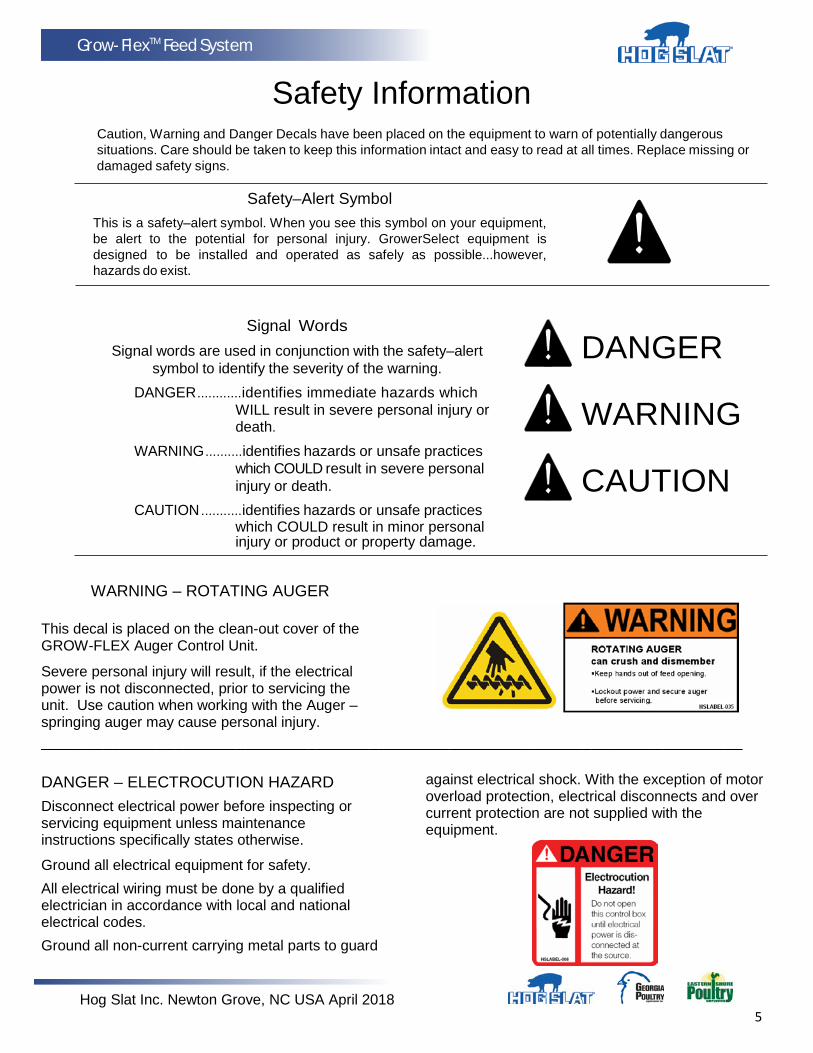
Caution, Warning and Danger Decals have been placed on the equipment to warn of potentially dangerous situations. Care should be taken to keep this information intact and easy to read at all times. Replace missing or damaged safety signs.
Safety–Alert Symbol
This is a safety–alert symbol. When you see this symbol on your equipment, be alert to the potential for personal injury. GrowerSelect equipment is designed to be installed and operated as safely as possible...however, hazards do exist.
Signal Words
Signal words are used in conjunction with the safety–alert symbol to identify the severity of the warning.
DANGER ............identifies immediate hazards which WILL result in severe personal injury or death.
WARNING ..........identifies hazards or unsafe practices which COULD result in severe personal injury or death.
CAUTION ...........identifies hazards or unsafe practices which COULD result in minor personal injury or product or property damage.
DANGER
WARNING
CAUTION
WARNING – ROTATING AUGER
This decal is placed on the clean-out cover of the GROW-FLEX Auger Control Unit.
Severe personal injury will result, if the electrical power is not disconnected, prior to servicing the unit. Use caution when working with the Auger – springing auger may cause personal injury.
_______________________________________________________________________________ DANGER – ELECTROCUTION HAZARD
Disconnect electrical power before inspecting or servicing equipment unless maintenance instructions specifically states otherwise.
Ground all electrical equipment for safety.
All electrical wiring must be done by a qualified electrician in accordance with local and national electrical codes.
Ground all non-current carrying metal parts to guard
against electrical shock. With the exception of motor overload protection, electrical disconnects and over current protection are not supplied with the equipment.

Hog Slat Inc. Newton Grove, NC USA April 2018 6
Grow-FlexTM Feed System
Selecting the System
GrowerSelect Feed Delivery systems are designed to handle most common livestock and poultry feeds. We cannot guarantee satisfactory operation with all formulations. We suggest that you contact our Technical Service Department concerning the use of new or unusual formulations.
GROW-FLEX Auger Feed Delivery Systems are the most versatile feed conveying systems available. Their ease of installation, reliability, low maintenance, and adaptability for many different applications, make them an indispensable part of any livestock feeding system.
The GROW-FLEX Auger Feed Delivery System you choose should be based on the following;
1. Particle Size - Feed particles that are too large for the system will cause damage to the particles, excessive power requirements, and plugging of the system.
2. Moisture Content (18% maximum) - The moisture content of the feed, among other factors, determines the amount of buildup that will occur on the auger and auger tubes when conveying feed. Feeds with high moisture content (above 18%) will freeze if exposed to freezing temperatures. This type of feed tends to flow less easily causing higher power requirements. Feeds in High Roughage (HR) applications should not exceed 27% moisture content. The HR system uses a Model 75 Auger inside of a Model 90 Grow-Flex tube in order to allow more clearance between the auger and the wall of the tube. HR is used in applications where moisture of the feed exceeds 18% but not more than 27% and also for larger particle size not to exceed 3/8” x 3/4” (10mm x 20mm).
3. Feed capacities - Each size of GROW-FLEX auger delivers feed at a different rate. These rates should be matched to your feed requirements. An application that requires a large volume of feed to be moved should use a larger (i.e. Model 90 or HR) auger system or possibly two smaller auger (i.e. Model 55 or 75) systems. See page 7 for System Comparison information.
4. Running Time - Size the system so that the maximum operating time is four hours per day (24 hours). If your system operating times exceed four hours per day, contact your distributor or Hog Slat’s Technical Service Department.
NOTE: The maximum allowable liquid molasses content for all GROW-FLEX Auger Feed Delivery Systems is 2% . At higher liquid molasses content or at moisture levels above the recommended limits, the auger tubes can become coated. This reduces the carrying capacity of the feed delivery system, causing eventual plugging of the system.

Hog Slat Inc. Newton Grove, NC USA April 2018 7
Grow-FlexTM Feed System
System Comparison Chart
System
Tube Dia.
Delivery Rate*
Feed Types
Max. Part.
Size
Model 55
2-1/4”
(55 mm)
15 lb/min. (7 kg/min.)
mash, crumbles
18% moist. content
1/8” x 1/2”
(3 mm x 13 mm)
Model 55 W/ Extended Pitch
Auger
2-1/4”
(55 mm)
18 lb/min. (8 kg/min.)
mash, crumbles
18% moist. content
1/8” x 1/2”
(3 mm x 13 mm)
Model 75
3”
(75 mm)
50 lb/min.
(22 kg/min.)
mash, crumbles
18% moist. content
1/8” x 1/2”
(3 mm x 13 mm)
Model 90
3-1/2” (90 mm)
100 lb/min. (45 kg/min.)
mash, pellets, shelled corn18% moist. content
3/16” x 1/2” (5 mm x 13 mm)
Model HR
3-1/2”
(90 mm)
50 lb/min.
(22 kg/min.)
high-moisture corn,
larger pellets, crumbles, mash
27% moist. content
3/8” x 3/4”
(10 mm x 20 mm)
*Conveying capacity is based on feed with 40 pounds per cubic feet (640 kg per cubic meter) density. Conveying capacities for all the GROW-FLEX auger systems are determined using 352 RPM Power Units.
Hog Slat Inc. Newton Grove, NC USA April 2018 8
Grow-FlexTM Feed System
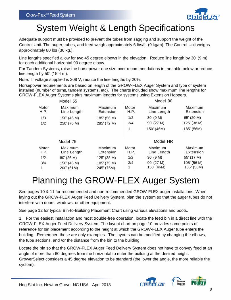
System Weight & Length Specifications Adequate support must be provided to prevent the tubes from sagging and support the weight of the Control Unit. The auger, tubes, and feed weigh approximately 6 lbs/ft. (9 kg/m). The Control Unit weighs approximately 80 lbs (36 kg.).
Line lengths specified allow for two 45 degree elbows in the elevation. Reduce line length by 30’ (9 m) for each additional horizontal 90 degree elbow. For Tandem Systems, raise the horsepower one size over recommendations in the table below or reduce line length by 50’ (15.4 m). Note: If voltage supplied is 208 V, reduce the line lengths by 20%. Horsepower requirements are based on length of the GROW-FLEX Auger System and type of system installed (number of turns, tandem systems, etc). The charts included show maximum line lengths for GROW-FLEX Auger Systems plus maximum lengths for systems using Extension Hoppers.
Model 55 Model 90 Motor Maximum Maximum Motor Maximum Maximum H.P. Line Length Extension H.P. Line Length Extension
1/3 150’ (46 M) 185’ (56 M) 1/2 30’ (9 M) 65’ (20 M) 1/2 250’ (76 M) 285’ (72 M) 3/4 90’ (27 M) 125’ (38 M)
1 150’ (46M) 185’ (56M)
Model 75 Model HR Motor Maximum Maximum Motor Maximum Maximum H.P. Line Length Extension H.P. Line Length Extension 1/2 80’ (26 M) 125’ (38 M) 1/2 30’ (9 M) 55’ (17 M) 3/4 1
150’ (46 M) 200’ (61M)
185’ (75 M) 245’ (75M)
3/4 1
90’ (27 M) 150’ (46M)
105’ (56 M) 185” (56M)
Planning the GROW-FLEX Auger System See pages 10 & 11 for recommended and non-recommended GROW-FLEX auger installations. When laying out the GROW-FLEX Auger Feed Delivery System, plan the system so that the auger tubes do not interfere with doors, windows, or other equipment.
See page 12 for typical Bin-to-Building Placement Chart using various elevations and boots.
1. For the easiest installation and most trouble-free operation, locate the feed bin in a direct line with the GROW-FLEX Auger Feed Delivery System. The layout chart on page 10 provides some points of reference for bin placement according to the height at which the GROW-FLEX Auger tube enters the building. Remember, these are only examples. The layouts can be modified by changing the elbows, the tube sections, and /or the distance from the bin to the building.
Locate the bin so that the GROW-FLEX Auger Feed Delivery System does not have to convey feed at an angle of more than 60 degrees from the horizontal to enter the building at the desired height. GrowerSelect considers a 45 degree elevation to be standard (the lower the angle, the more reliable the system).
Hog Slat Inc. Newton Grove, NC USA April 2018 9
Grow-FlexTM Feed System
2. Lay out the system as straight as possible. Avoid extra elbows and curves by locating the feed bin in line with the feeders. One horizontal 90 degree turn is permissible inside the building. 180 degree turns are not recommended under any conditions.
If additional turns or elbows are required, use extension hoppers. Remember: one 90 degree elbow requires the same power as 30’ (9.1 m) of straight line.
3. Plan the system so that the auger tubes are directly over the feeders or hoppers to be filled as possible. The drop tubes may be angled up to a maximum of 45 degrees from the vertical if necessary. At angles greater than 45 degrees, bridging in the drop tubes may occur.
4. The control unit must be located over a feeder or hopper that will require as much or more feed than any of the other feeders or hoppers. If frequent filling is desired, mount the drop tube switch or hopper level switch low so that this feeder or hopper will have a low feed level. This causes the feeder to call for feed more often, the system will restart, and the other feeders will be refilled sooner.
5. Do not locate outlet drops on or just before an elbow. Install the drop after the elbow so feed will cushion the auger through the curve. If there is some reason why the outlet drop cannot be moved, it must have some “feed bypass” to cushion the auger through the elbow.
6. Avoid horizontal left-hand turns if possible. The elbow in a left-hand turn is not cushioned by the feed and will wear faster. On systems with a 90 degree horizontal left-hand turn, reduce the stretch to reduce wear.
NOTE: A rule of thumb for left-hand turns is to reduce stretch to 1" per 50’ (25 mm per 15.2 m) on initial installation. Increase the stretch if necessary.
If an extension hopper is used:
A. Locate the hopper so there will not be any outlet drops on the short tube or elbow leading out of the hopper.
B. The longer portion of the system with most of the outlet drops should follow the extension hopper. For example: in a 300’ (91.4 m) Model 75 System the distance from the bin to the extension hopper should be 100’ (30.5 m). From the extension hopper to the control unit should be 200’ (61 m) with most outlets placed on the 200’ (61 m) section. Refer to chart on page 8, for power unit requirements.
C. NOTE: The lower part of the extension hopper can be turned 90 degrees to the left or right in relation to the top portion of the extension hopper. This allows the extension hopper to replace a horizontal elbow where both might be located in approximately the same position in the system.
7. Remember the following points when installing a Tandem System or Twin Tandem System:
A. The Tandem bin arrangement uses one continuous auger. B. The Twin Tandem bin arrangement uses two separate augers and power units. C. Pour one level concrete pad for both bins (in either system). D. Position bins so that legs will not interfere with the GROW-FLEX Auger System (in either system). 8. Use the chart on page 8 to determine maximum line lengths and power unit requirements. 9. The minimum length specification for Grow-Flex auger on outside of building is: 15 feet for a single bin with a 30 degree boot, and 30 feet for a Tandem bin setup.
Hog Slat Inc. Newton Grove, NC USA April 2018 10
Grow-FlexTM Feed System
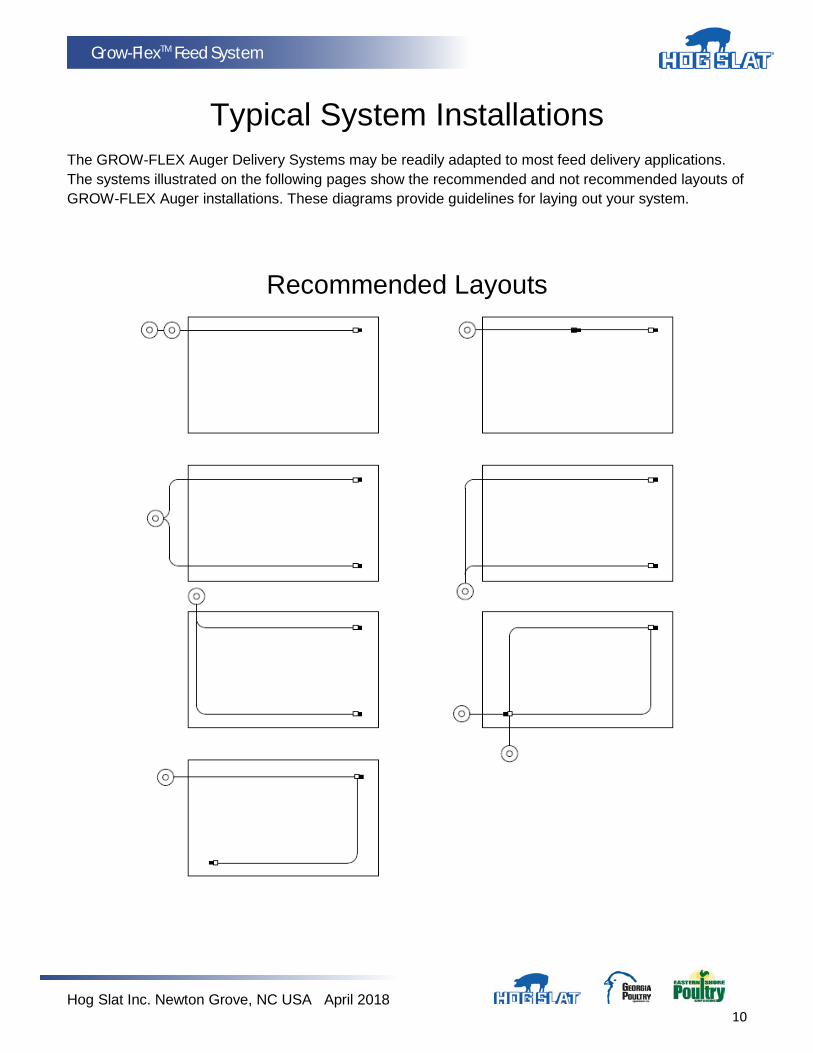
Typical System Installations The GROW-FLEX Auger Delivery Systems may be readily adapted to most feed delivery applications. The systems illustrated on the following pages show the recommended and not recommended layouts of GROW-FLEX Auger installations. These diagrams provide guidelines for laying out your system.
Recommended Layouts

Hog Slat Inc. Newton Grove, NC USA April 2018 11
Grow-FlexTM Feed System
Not Recommended Layouts
Hog Slat Inc. Newton Grove, NC USA April 2018 12
Grow-FlexTM Feed System
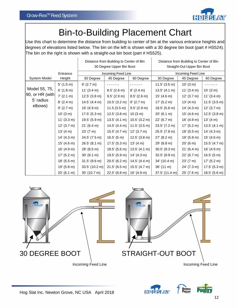
Bin-to-Building Placement Chart Use this chart to determine the distance from building to center of bin at the various entrance heights and degrees of elevations listed below. The bin on the left is shown with a 30 degree bin boot (part # HS524). The bin on the right is shown with a straight-out bin boot (part # HS525).
Entrance System Model Height
Distance from Building to Center of Bin 30 Degree Upper Bin Boot
Incoming Feed Line
Distance from Building to Center of Bin Straight-Out Upper Bin Boot
Incoming Feed Line
30 Degree 45 Degree 60 Degree 30 Degree 45 Degree 60 Degree Model 55, 75,
90, or HR (with 5’ radius elbows)
5’ (1.5 m)
6’ (1.8 m)
7’ (2.1 m)
8’ (2.4 m)
9’ (2.7 m)
10’ (3 m)
11’ (3.3 m)
12’ (3.7 m)
13’ (4 m)
14’ (4.3 m)
15’ (4.6 m)
16’ (4.9 m)
17’ (5.2 m)
18’ (5.5 m)
19’ (5.8 m)
20’ (6.1 m)
9‘ (2.7 m)
11’ (3.4 m)
12.5’ (3.8 m)
14.5’ (4.4 m)
16’ (4.9 m)
17.5’ (5.3 m)
19.5’ (5.9 m)
21’ (6.4 m)
23’ (7 m)
24.5’ (7.5 m)
26.5’ (8.1 m)
28’ (8.5 m)
30’ (9.1 m)
31.5’ (9.6 m)
33.5’ (10.2 m)
35’ (10.7 m)
- - - - - -
8.5’ (2.6 m)
9.5’ (2.9 m)
10.5’ (3.2 m)
11.5 (3.5 m)
12.5’ (3.8 m)
13.5’ (4.1 m)
14.5’ (4.4 m)
15.5’ (4.7 m)
16.5’ (5 m)
17.5’ (5.3 m)
18.5’ (5.6 m)
19.5’ (5.9 m)
20.5’ (6.2 m)
21.5’ (6.5 m)
22.5’ (6.8 m)
- - - - - -
8’ (2.4 m)
8.5’ (2.6 m)
9’ (2.7 m)
9.5’ (2.9 m)
10 (3 m)
10.5’ (3.2 m)
11.5’ (3.5 m)
12’ (3.7 m)
12.5’ (3.8 m)
13’ (4 m)
13.5’ (4.1 m)
14’ (4.3 m)
14.5’ (4.4 m)
15.5’ (4.7 m)
16’ (4.9 m)
11.5’ (3.5 m)
13.5’ (4.1 m)
15’ (4.6 m)
17’ (5.2 m)
18.5’ (5.6 m)
20’ (6.1 m)
22’ (6.7 m)
23.5’ (7.2 m)
25.5’ (7.8 m)
27’ (8.2 m)
29’ (8.8 m)
30.5’ (9.3 m)
32.5’ (9.9 m)
34’ (10.4 m)
36’ (11 m)
37.5’ (11.4 m)
10’ (3 m)
11’ (3.4 m)
12’ (3.7 m)
13’ (4 m)
14’ (4.3 m)
15’ (4.6 m)
16’ (4.9 m)
17’ (5.2 m)
18’ (5.5 m)
19’ (5.8 m)
20’ (6 m)
21’ (6.4 m)
22’ (6.7 m)
23’ (7 m)
24’ (7.3 m)
25’ (7.6 m)
- - - - - -
10‘ (3 m)
11’ (3.4 m)
11.5’ (3.5 m)
12’ (3.7 m)
12.5’ (3.8 m)
13’ (4 m)
13.5’ (4.1 m)
14’ (4.3 m)
15’ (4.6 m)
15.5’ (4.7 m)
16’ (4.9 m)
16.5’ (5 m)
17’ (5.2 m)
17.5’ (5.3 m)
18.5’ (5.6 m)
30 DEGREE BOOT STRAIGHT-OUT BOOT Incoming Feed Line Incoming Feed Line
Hog Slat Inc. Newton Grove, NC USA April 2018 13
Grow-FlexTM Feed System
Installation Instructions for the GROW-FLEX Auger Feed Delivery System
Install the equipment as specified in this manual. Failure to install as specified may cause damage to the equipment and/or cause personal injury or death.
Take special notice of the warnings and safety decals on the equipment and in this manual. Always wear protective clothing and protective glasses when working with the equipment.
Discarded materials, equipment, and boxes may be recycled. Recycle according to local and national codes.
Unless otherwise specified, the Model 55, 75, 90, & HR Systems are installed similarly.
All the systems are available with straight-out or 30 degree upper boots.
Bin Location and Collar Information For easiest installation and trouble-free operation, locate the feed bin in a direct line with the GROW-FLEX Auger System. The layout chart provides some points of reference for bin placement according to the height at which the system enters the building.
The bin collar is installed during bulk bin assembly. GrowerSelect bins have a welded collar. Bin Adapter Kits are available to modify existing bins so that the welded collar can be used. In addition, most other feed bin manufacturers have a collar available to be used with GrowerSelect GROW-FLEX Auger Feed Delivery Systems.
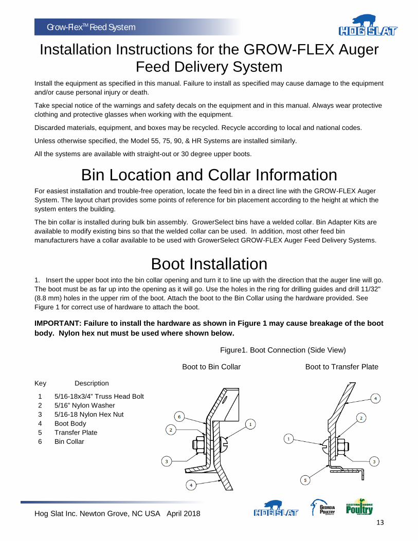
Boot Installation 1. Insert the upper boot into the bin collar opening and turn it to line up with the direction that the auger line will go. The boot must be as far up into the opening as it will go. Use the holes in the ring for drilling guides and drill 11/32" (8.8 mm) holes in the upper rim of the boot. Attach the boot to the Bin Collar using the hardware provided. See Figure 1 for correct use of hardware to attach the boot.
IMPORTANT: Failure to install the hardware as shown in Figure 1 may cause breakage of the boot body. Nylon hex nut must be used where shown below.
Figure1. Boot Connection (Side View)
Boot to Bin Collar Boot to Transfer Plate
Key Description
1 5/16-18x3/4” Truss Head Bolt 2 5/16” Nylon Washer 3 5/16-18 Nylon Hex Nut 4 Boot Body 5 Transfer Plate 6 Bin Collar
Hog Slat Inc. Newton Grove, NC USA April 2018 14
Grow-FlexTM Feed System
Boot Installation (Continued)
2. Attach the transfer plate to the lower section of upper boot. Use truss head bolts installed from the inside of the plate and place nylon washers under the nylon nuts as shown in Figure 1.
3. Insert the slide into the transfer plate slot so that it is in its operating position before bolting the slide shield in place. Use two hex bolts 5/16-18x3/4" and serrated flange nuts to secure the shield.
4. Bolt the lower boot (unloader) to the transfer plate using four 5/16-18x3/4" hex bolts and serrated flange nuts.
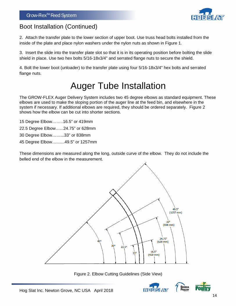
Auger Tube Installation The GROW-FLEX Auger Delivery System includes two 45 degree elbows as standard equipment. These elbows are used to make the sloping portion of the auger line at the feed bin, and elsewhere in the system if necessary. If additional elbows are required, they should be ordered separately. Figure 2 shows how the elbow can be cut into shorter sections.
15 Degree Elbow……..16.5” or 419mm 22.5 Degree Elbow…...24.75” or 628mm 30 Degree Elbow……...33” or 838mm 45 Degree Elbow….......49.5” or 1257mm
These dimensions are measured along the long, outside curve of the elbow. They do not include the belled end of the elbow in the measurement.
Figure 2. Elbow Cutting Guidelines (Side View)

Hog Slat Inc. Newton Grove, NC USA April 2018 15
Grow-FlexTM Feed System
1. Determine where the entrance hole for the auger tube must be located on the building and cut a hole large enough to fit tubing.
2. Place provided seal ring (location #3 in Figure 3) and neoprene seal (location #4) over the straight end of the elbow (item #1 in Figure 3). Insert elbow with straight end into building entrance hole. Secure seals to outside of building with required hardware. Position and cut (if required) the elbow at desired length to ensure that auger inside building will be horizontal.
Figure 3. Bin to building elbow and tube layout diagram (Side View) (Single & Quad Unloaders)
3. Model 75, 90, & HR: Slide the belled end of the auger tube item #2 over the outlet end of the unloader. (Recommendation: a short section of auger tube should be cut approximately 12” long and attach the belled end to unloader outlets.) A clamp is provided to secure the auger tube to the unloader. Attach bell end of additional auger tubes or elbow to short section of auger tube as required. Do not connect elbow tubes directly onto unloaders.
Model 55: Install a straight section of Model 55 auger tube (approximately 12” long) over the outlet end of the unloader. Do not assemble the belled end of auger tube to the unloader. A clamp is provided to secure the auger tube to the unloader. Attach bell end of additional auger tubes or elbow as required.
4. Place the end of a straight section of tube inside the belled end of the elbow extending from building. Hold the straight section of auger tube so that it touches the elbow on the unloader side. Mark the spot where the tube aligns with the "unloader" elbow and cut the elbow at that point.
5. Place the belled end of the auger tube over the end of the elbow that was just cut, and hold the tube against the top elbow. Cut the auger tube long enough to fit inside the belled end of the elbow in the building. Figure 4 shows the direction the auger is to run in relation to the belled end of the tube. (Note: some installations may only require auger tubes and a single elbow which enters the building.)
Key Description
1 Straight section of Auger Tube
2 Belled end of Auger Tube
1 2
DIRECTION OF TRAVEL
Figure 4. Proper Auger Tube Connection (Side View)

Hog Slat Inc. Newton Grove, NC USA April 2018 16
Grow-FlexTM Feed System
6. When connecting auger tubes to unloaders inside of building, it is also recommended to cut a short section of auger tube approximately 12” long and attach the belled end of tube to unloader outlets. Do not connect elbow tubes directly onto unloaders.
7. Dry-fit all parts. When satisfied that elbows and tubes fit together smoothly, glue with PVC cement according to the following instructions.
The auger tubes and elbows for the GROW-FLEX Auger systems are made of specially formulated PVC tubing. Use the PVC solvent cement to make strong, reliable bonds.
FOLLOW DIRECTIONS ON THE CAN FOR SAFE HANDLING OF CEMENT.
a. Be sure tube is cut off squarely. Remove burrs from outside and inside the end of the tube. b. Dry fit all parts. Tube should fit inside belled end of next tube to full depth without excess force. c. Clean surfaces to be joined. SURFACES MUST BE FREE OF DIRT OR GREASE! d. Apply a generous coat of cement to both the inside of the belled end and outside of the other
tube. Be sure cement covers all of the joint area so there are no bare spots. e. Quickly join the tubes, giving them a twisting motion to bring them into alignment as they are
joined. f. Keep pressure on the joint until the PVC cement sets up.
8. ALL TUBE JOINTS EXPOSED TO MOISTURE AND WEATHER MUST BE SEALED OR CAULKED TO WATERPROOF THEM IN ADDITION TO CEMENTING OR CLAMPING THE JOINT!
9. If there is more than 15 feet (4.5 meters) of auger tube between the boot and the building, provide additional support for the tubes so that the boot does not have to carry the weight of the auger. Extra support can be achieved with cables or chains fastened to the bin legs and auger tube.
10. Install the remaining tubes in the system AFTER the outlet holes have been located and cut. The auger tubes should be cemented using PVC cement supplied. NOTE: The tubes can be joined by cutting off the belled ends and fastening tubes together with tube connectors if there is some reason why permanent installation is not desired. (Tube Connectors are not standard equipment and must be ordered separately for this type of installation).
Supporting the System-Inside the Building Support the auger tubing with chain and “S” hooks every 5 feet (1.5 m). The system should be restrained from swinging by using chain and “S” hooks to brace the auger tube, every 20 feet (6 m), as shown in Figure 5.
Horizontal elbows need to be supported in at least two places. Chain, screw hooks, and “S” hooks are supplied as a suspension kit for supporting the equipment. Keep the line as level and straight as possible.
If Drop Feeders, Extension Hoppers, Outlet Drops with long angled Drop Tubes, or other loads are imposed on the system, extra support must be added at that point.
Hog Slat Inc. Newton Grove, NC USA April 2018 17
Grow-FlexTM Feed System
Power Units require extra support to resist the twisting encountered when the motor starts and stops. Use all of the “ears” on the gearhead as well as the suspension points provided on the HS593 Control Unit Box to support the Power Unit.
Adequate chain and “S” hooks are provided with each system to properly support it.
Other means of supporting the system are permissible as long as the system receives the correct support and the auger tube is not dented or flattened. Alternative support systems must allow for expansion and contraction of the auger tubes.
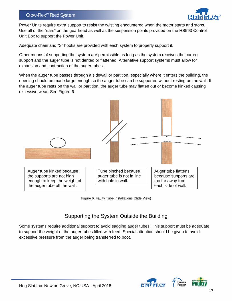
When the auger tube passes through a sidewall or partition, especially where it enters the building, the opening should be made large enough so the auger tube can be supported without resting on the wall. If the auger tube rests on the wall or partition, the auger tube may flatten out or become kinked causing excessive wear. See Figure 6.
Figure 6. Faulty Tube Installations (Side View)
Supporting the System Outside the Building
Some systems require additional support to avoid sagging auger tubes. This support must be adequate to support the weight of the auger tubes filled with feed. Special attention should be given to avoid excessive pressure from the auger being transferred to boot.
Auger tube kinked because the supports are not high enough to keep the weight of the auger tube off the wall.
Tube pinched because auger tube is not in line with hole in wall.
Auger tube flattens because supports are too far away from each side of wall.
Hog Slat Inc. Newton Grove, NC USA April 2018 18
Grow-FlexTM Feed System
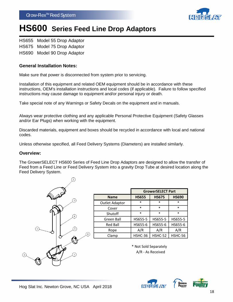
HS600 Series Feed Line Drop AdaptorsHS655 Model 55 Drop Adaptor HS675 Model 75 Drop Adaptor HS690 Model 90 Drop Adaptor General Installation Notes:
Make sure that power is disconnected from system prior to servicing.
Installation of this equipment and related OEM equipment should be in accordance with these instructions, OEM’s installation instructions and local codes (if applicable). Failure to follow specified instructions may cause damage to equipment and/or personal injury or death.
Take special note of any Warnings or Safety Decals on the equipment and in manuals.
Always wear protective clothing and any applicable Personal Protective Equipment (Safety Glasses and/or Ear Plugs) when working with the equipment.
Discarded materials, equipment and boxes should be recycled in accordance with local and national codes.
Unless otherwise specified, all Feed Delivery Systems (Diameters) are installed similarly.
Overview:
The GrowerSELECT HS600 Series of Feed Line Drop Adaptors are designed to allow the transfer of Feed from a Feed Line or Feed Delivery System into a gravity Drop Tube at desired location along the Feed Delivery System.
Name HS655 HS675 HS690Outlet Adaptor * * *
Cover * * *Shutoff * * *
Green Ball HS655-5 HS655-5 HS655-5Red Ball HS655-6 HS655-6 HS655-6
Rope A/R A/R A/RClamp HSHC-36 HSHC-52 HSHC-56
* Not Sold Separately A/R - As Received
GrowerSELECT Part

Hog Slat Inc. Newton Grove, NC USA April 2018 19
Grow-FlexTM Feed System
Installation:
1. Determine the desired location for the Outlet Drop. Drill or cut the desired outlet hole based on system requirement of Standard Outlet or Total Drop-Out Outlet. Reference Figures and Charts below.
Model Item 1 Item 2 55 1-1/2” Dia. (38 mm) 3” (76 mm)
75 2 1/2” Dia. (63 mm) 5” (127 mm)
90 3” Dia. (76 mm) 6” (152 mm)
2. Tie an overhand knot in Cord provided located at center of Cord length. Assemble Cord with Knot into retainer pocket of the Shutoff making sure that cord is fully seated in slots.
Hog Slat Inc. Newton Grove, NC USA April 2018 20
Grow-FlexTM Feed System
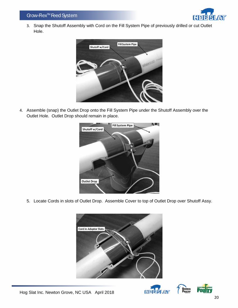
3. Snap the Shutoff Assembly with Cord on the Fill System Pipe of previously drilled or cut Outlet Hole.
4. Assemble (snap) the Outlet Drop onto the Fill System Pipe under the Shutoff Assembly over the Outlet Hole. Outlet Drop should remain in place.
5. Locate Cords in slots of Outlet Drop. Assemble Cover to top of Outlet Drop over Shutoff Assy.
Hog Slat Inc. Newton Grove, NC USA April 2018 21
Grow-FlexTM Feed System
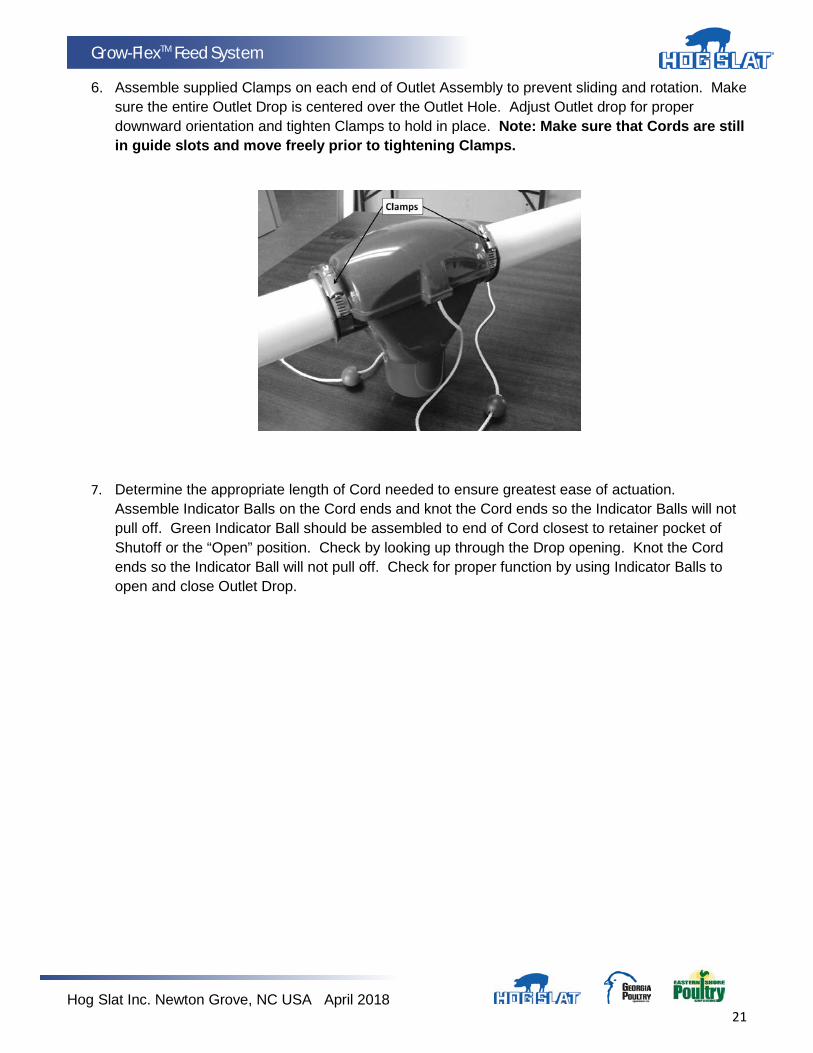
6. Assemble supplied Clamps on each end of Outlet Assembly to prevent sliding and rotation. Make sure the entire Outlet Drop is centered over the Outlet Hole. Adjust Outlet drop for proper downward orientation and tighten Clamps to hold in place. Note: Make sure that Cords are still in guide slots and move freely prior to tightening Clamps.
7. Determine the appropriate length of Cord needed to ensure greatest ease of actuation. Assemble Indicator Balls on the Cord ends and knot the Cord ends so the Indicator Balls will not pull off. Green Indicator Ball should be assembled to end of Cord closest to retainer pocket of Shutoff or the “Open” position. Check by looking up through the Drop opening. Knot the Cord ends so the Indicator Ball will not pull off. Check for proper function by using Indicator Balls to open and close Outlet Drop.
Hog Slat Inc. Newton Grove, NC USA April 2018 22
Grow-FlexTM Feed System
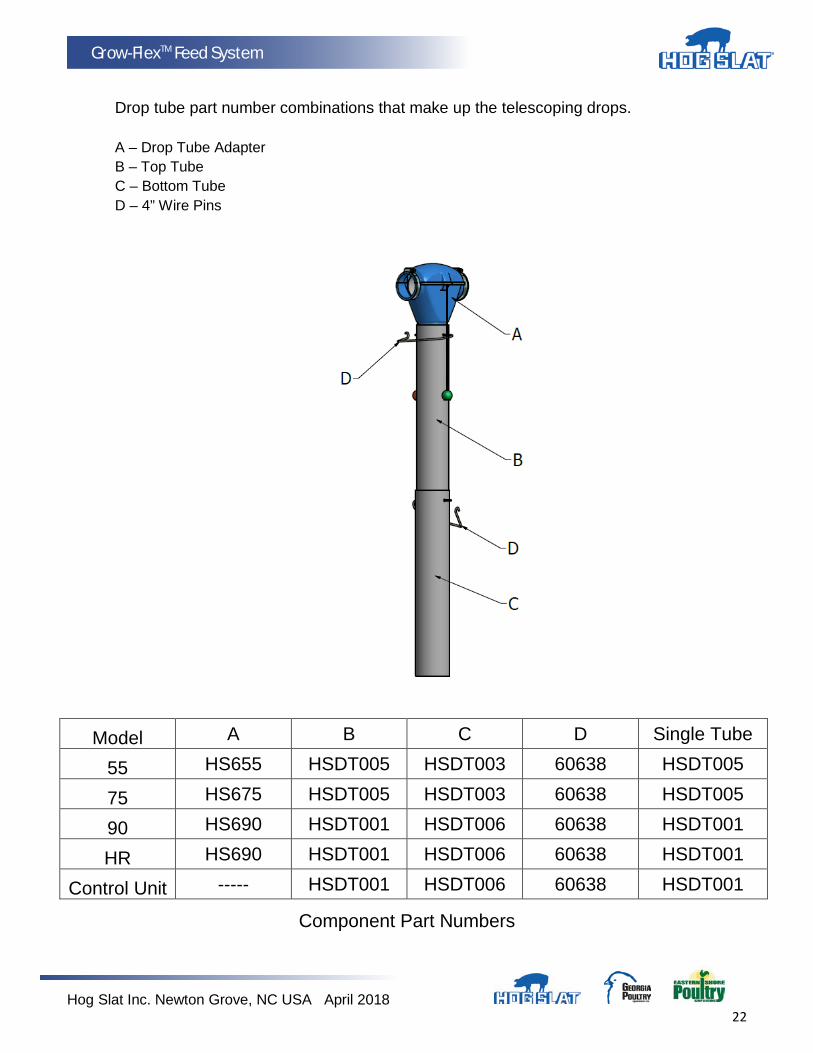
Drop tube part number combinations that make up the telescoping drops. A – Drop Tube Adapter B – Top Tube C – Bottom Tube D – 4” Wire Pins
Model A B C D Single Tube
55 HS655 HSDT005 HSDT003 60638 HSDT005
75 HS675 HSDT005 HSDT003 60638 HSDT005
90 HS690 HSDT001 HSDT006 60638 HSDT001
HR HS690 HSDT001 HSDT006 60638 HSDT001
Control Unit ----- HSDT001 HSDT006 60638 HSDT001
Component Part Numbers
Hog Slat Inc. Newton Grove, NC USA April 2018 23
Grow-FlexTM Feed System
HS593 Feed Line Control Unit – 240V Single Phase
Note: Control Unit is to be wired in accordance with all applicable local and national electrical wiring codes. All wiring sizes and fuse capacities are to be sized according to applicable electrical code specifications or other regulations. Safety Instructions: Read all safety messages in this manual and on equipment safety decals. Follow recommended precautions and safe operating practices. Ground all electrical equipment for safety. Ground all non-current carrying metal parts to guard against electrical shock. Always keep safety decals in good condition and replace missing or damaged decals. Overview: The GrowerSELECT HS593 Control Unit is designed for use with a flexible auger feed system where control of an auger drive motor is required. Power to the auger drive motor is done through feed pressure being applied to a diaphragm coupled to an electrical switch internal to the control unit housing. This switch is used to control the auger drive motor by turning off the power when feed is present and turning on the power when feed has been removed from the control unit housing. The sensitivity of the electrical switch is not adjustable. MAXIMUM LOAD RATING: 1 ½ HP @ 230VAC A red indicator light on the side of the switch housing will illuminate when the diaphragm has been pressed (MOTOR OFF) and the switch has been activated. The ON/OFF switch is used to enable or disable the Control Unit. DO NOT USE THIS SWITCH AS DISCONNECTING MEANS FOR SERVICING.
Hog Slat Inc. Newton Grove, NC USA April 2018 24
Grow-FlexTM Feed System
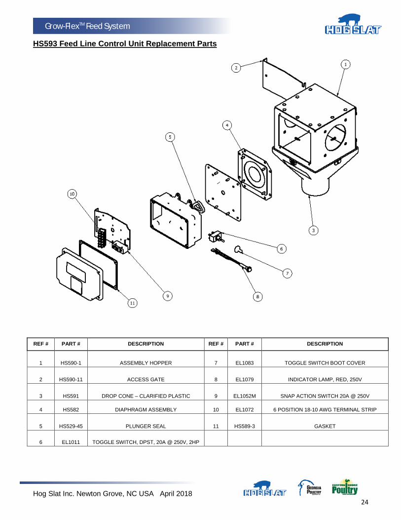
HS593 Feed Line Control Unit Replacement Parts
REF # PART # DESCRIPTION REF # PART # DESCRIPTION
1 HS590-1 ASSEMBLY HOPPER 7 EL1083 TOGGLE SWITCH BOOT COVER
2 HS590-11 ACCESS GATE 8 EL1079 INDICATOR LAMP, RED, 250V
3 HS591 DROP CONE – CLARIFIED PLASTIC 9 EL1052M SNAP ACTION SWITCH 20A @ 250V
4 HS582 DIAPHRAGM ASSEMBLY 10 EL1072 6 POSITION 18-10 AWG TERMINAL STRIP
5 HS529-45 PLUNGER SEAL 11 HS589-3 GASKET
6 EL1011 TOGGLE SWITCH, DPST, 20A @ 250V, 2HP
Hog Slat Inc. Newton Grove, NC USA April 2018 25
Grow-FlexTM Feed System
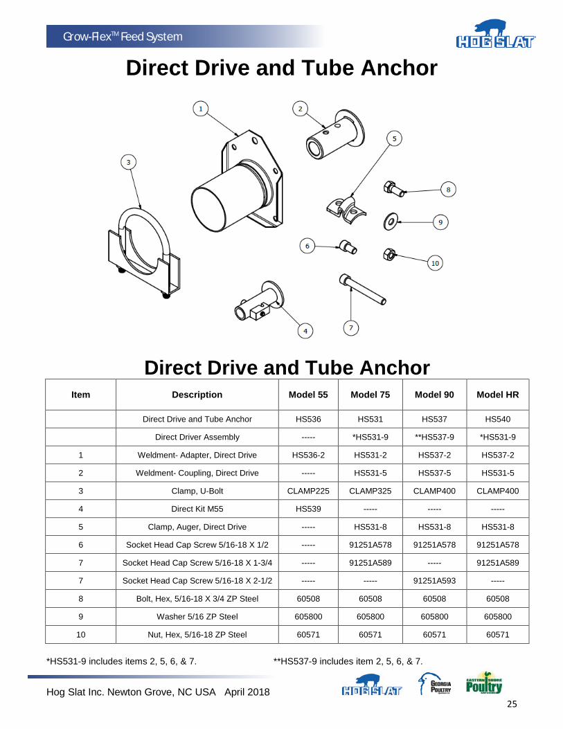
Direct Drive and Tube Anchor
Direct Drive and Tube Anchor Item Description Model 55 Model 75 Model 90 Model HR
Direct Drive and Tube Anchor HS536 HS531 HS537 HS540
Direct Driver Assembly ----- *HS531-9 **HS537-9 *HS531-9
1 Weldment- Adapter, Direct Drive HS536-2 HS531-2 HS537-2 HS537-2
2 Weldment- Coupling, Direct Drive ----- HS531-5 HS537-5 HS531-5
3 Clamp, U-Bolt CLAMP225 CLAMP325 CLAMP400 CLAMP400
4 Direct Kit M55 HS539 ----- ----- -----
5 Clamp, Auger, Direct Drive ----- HS531-8 HS531-8 HS531-8
6 Socket Head Cap Screw 5/16-18 X 1/2 ----- 91251A578 91251A578 91251A578
7 Socket Head Cap Screw 5/16-18 X 1-3/4 ----- 91251A589 ----- 91251A589
7 Socket Head Cap Screw 5/16-18 X 2-1/2 ----- ----- 91251A593 -----
8 Bolt, Hex, 5/16-18 X 3/4 ZP Steel 60508 60508 60508 60508
9 Washer 5/16 ZP Steel 605800 605800 605800 605800
10 Nut, Hex, 5/16-18 ZP Steel 60571 60571 60571 60571
*HS531-9 includes items 2, 5, 6, & 7. **HS537-9 includes item 2, 5, 6, & 7.

Hog Slat Inc. Newton Grove, NC USA April 2018 26
Grow-FlexTM Feed System
Installation: 1. (Figure 1) illustrates a typical installation example of the HS593 control unit.
a. Mount tube anchor to one side using (4) 5/16” x ¾” bolts with (4) flat washers. b. Mount auger power drive unit gear box secured with (4) 5/16” x ¾” bolts and (4) flat washers.
FIGURE 1
2. The HS593 Control Unit must be hardwired. See (Figure 2) for factory wiring diagram. 3. See (Figure 3) for wiring diagram for external connections. 4. When connecting wire from equipment to terminal strip, remove no more than ¼” of insulation from
end of wire. Be sure there are no stray wire strands before inserting wire into terminal strip. Insert wire into terminal ¼” and tighten terminal strip set screw.
5. When using Hopper Level Control Switch, switch should be wired as “Normally Closed” contact. 6. If No Hopper Level Control Switch is to be used, place jumper wire between terminals (5) and (6). 7. Use provided self tapping screws to provide bonding to Control Unit Switch Assembly and other
connected equipment. THIS BOX DOES NOT GROUND METAL CONNECTORS! 8. Pilot indentions are provided and located to allow for sufficient clearance for ½” watertight
connectors. USE WATERTIGHT NON-METALLIC BOX CONNECTORS ONLY. 9. Care should be taken when drilling pilot holes to prevent damage to wires or other components.
FIGURE 2 FIGURE 3

Hog Slat Inc. Newton Grove, NC USA April 2018 27
Grow-FlexTM Feed System
HS10 Feed Sensor Specifications:
Operating Voltage: 90-250 VAC Frequency: 50-60 Hz Relay Contact Maximum Current Load: 5A Resistive and 2A Inductive (Motors and Relays) Sensitivity: 0-9/16” (Factory Setting is for ¼”) Time Delay Range: 0-4 Hours (Factory Setting is for 30 seconds) Ambient Operating Temperature: -4°F-+158°F Cord: Length= 5’ 18-5 SJTW
These instructions are guidelines for new GrowerSelect installation in four (4) wire Sensor control units. In all cases, the OEM (Original Equipment Manufacturer) wiring instructions should be followed if possible.
It is in no way to be used to violate or supersede local, state and national wiring codes. All wiring sizes and fuse capacities are to be sized according to national electrical code specifications or other applicable regulations.
For the purpose of installation:
• NC (Normally Closed) is defined as contacts closed (runs) with power supply connected to sensor and no product in contact with sensor. (Black wires marked #1 & #3)
• NO (Normally Open) is defined as contacts open (does not run) with power supply connected to sensor and no product in contact with sensor. (Black wires marked #1 & #4)
• COM (Common) is defined as common or supply for sensor circuit used in conjunction with NO or NC leads. (Black Lead #1)
• L1 (Line 1) is defined as Line 1 of power supply circuit. (Brown wire) • L2 (Line 2) is defined as Line 2 of power supply circuit. (Blue wire)
Mounting: Sensor should be installed consistent with existing sensor mounting in rubber grommet or other suitable mount. Replacement grommets can be purchased at your local Hog Slat retailer. Sensor should be inserted into grommet so that 1/2” minimum of sensor protrudes past grommet into grain/feed area (Figure 1). It should be secured with supplied Nylon cable tie. Do not use hose clamp!
For new installations, use HS10-2 mounting kit and position sensor as shown in Figure 1.
Figure 1
Hog Slat Inc. Newton Grove, NC USA April 2018 28
Grow-FlexTM Feed System
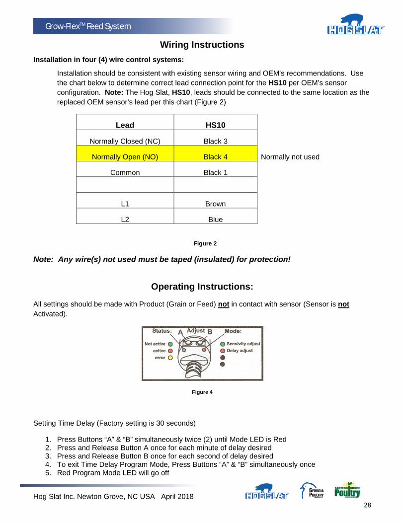
Wiring Instructions Installation in four (4) wire control systems:
Installation should be consistent with existing sensor wiring and OEM’s recommendations. Use the chart below to determine correct lead connection point for the HS10 per OEM’s sensor configuration. Note: The Hog Slat, HS10, leads should be connected to the same location as the replaced OEM sensor’s lead per this chart (Figure 2)
Lead HS10
Normally Closed (NC) Black 3
Normally Open (NO) Black 4 Normally not used
Common Black 1
L1 Brown
L2 Blue
Figure 2
Note: Any wire(s) not used must be taped (insulated) for protection!
Operating Instructions:
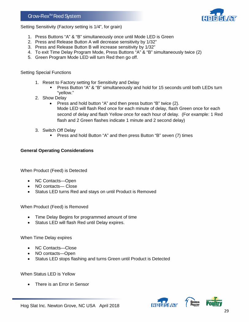
All settings should be made with Product (Grain or Feed) not in contact with sensor (Sensor is not Activated).
Figure 4
Setting Time Delay (Factory setting is 30 seconds)
1. Press Buttons “A” & “B” simultaneously twice (2) until Mode LED is Red 2. Press and Release Button A once for each minute of delay desired 3. Press and Release Button B once for each second of delay desired 4. To exit Time Delay Program Mode, Press Buttons “A” & “B” simultaneously once 5. Red Program Mode LED will go off
Hog Slat Inc. Newton Grove, NC USA April 2018 29
Grow-FlexTM Feed System
Setting Sensitivity (Factory setting is 1/4”, for grain)
1. Press Buttons “A” & “B” simultaneously once until Mode LED is Green 2. Press and Release Button A will decrease sensitivity by 1/32” 3. Press and Release Button B will increase sensitivity by 1/32” 4. To exit Time Delay Program Mode, Press Buttons “A” & “B” simultaneously twice (2) 5. Green Program Mode LED will turn Red then go off.
Setting Special Functions
1. Reset to Factory setting for Sensitivity and Delay Press Button “A” & “B” simultaneously and hold for 15 seconds until both LEDs turn
“yellow.” 2. Show Delay
• Press and hold button “A” and then press button “B” twice (2). Mode LED will flash Red once for each minute of delay, flash Green once for each second of delay and flash Yellow once for each hour of delay. (For example: 1 Red flash and 2 Green flashes indicate 1 minute and 2 second delay)
3. Switch Off Delay Press and hold Button “A” and then press Button “B” seven (7) times
General Operating Considerations
When Product (Feed) is Detected
• NC Contacts—Open • NO contacts— Close • Status LED turns Red and stays on until Product is Removed
When Product (Feed) is Removed
• Time Delay Begins for programmed amount of time • Status LED will flash Red until Delay expires.
When Time Delay expires
• NC Contacts—Close • NO contacts—Open • Status LED stops flashing and turns Green until Product is Detected
When Status LED is Yellow
• There is an Error in Sensor
Hog Slat Inc. Newton Grove, NC USA April 2018 30
Grow-FlexTM Feed System
HS529 Hopper Level Control Part List · Wiring · Installation
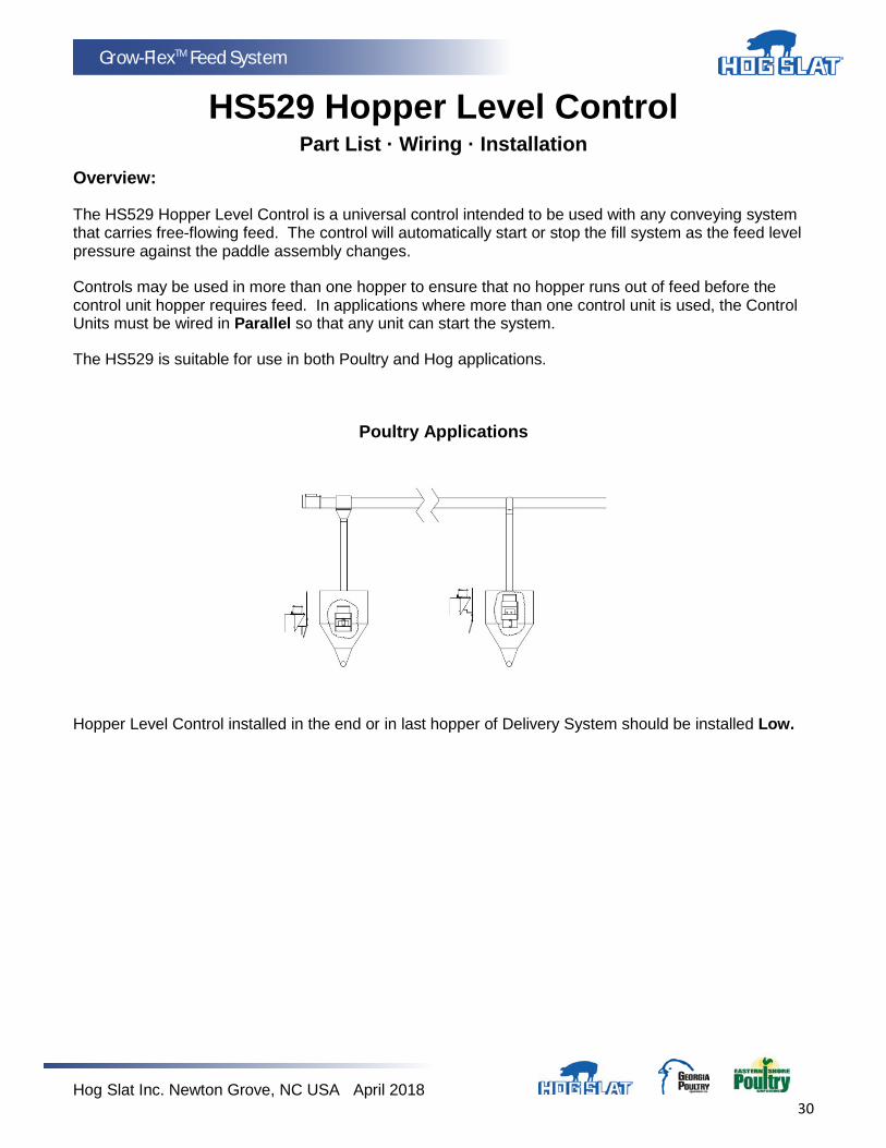
Overview:
The HS529 Hopper Level Control is a universal control intended to be used with any conveying system that carries free-flowing feed. The control will automatically start or stop the fill system as the feed level pressure against the paddle assembly changes.
Controls may be used in more than one hopper to ensure that no hopper runs out of feed before the control unit hopper requires feed. In applications where more than one control unit is used, the Control Units must be wired in Parallel so that any unit can start the system.
The HS529 is suitable for use in both Poultry and Hog applications.
Poultry Applications
Hopper Level Control installed in the end or in last hopper of Delivery System should be installed Low.

Hog Slat Inc. Newton Grove, NC USA April 2018 31
Grow-FlexTM Feed System
Hog Applications
For the majority of Hog Installations, the Hopper Level Control is installed in the last hopper that is located at the end of the Delivery System.
Installation:
The HS529 Hopper Level Control should be installed in the last hopper or feeder which is located at the end of the delivery or fill system. The unit should be mounted low in the hopper or feeder so the fill level in the control hopper will be lower than the others. This will cause the fill system to cycle more frequently ensuring a proper feed level in every hopper or feeder. It will also provide a reservoir of feed in the system if another control hopper calls for feed. The feed drop tube should be positioned so that feed is delivered to the center and near the top of the control in front of paddle. Drop tubes and other control units should be positioned high in other hoppers or feeders so that they will fill but not overflow.
Important: The HS529 must be mounted vertically to ensure the proper movement of the switch and paddle assembly.
HS529 Hopper Level Control Mounted Vertically Determine the desired placement of the Control Unit and drill (2) 9/32” (7.2mm) diameter holes using the Mounting Bracket as a guide to determine hole spacing. Assemble the mounting bracket using the supplier 1/4-20 hex bolts and lock nuts.
(For those applications where there is not a suitable vertical surface on the hopper or feeder; the Mounting Bracket should be bent or formed to ensure the Control unit is completely vertical when installed into the Mounting Bracket.)
Install the Control Unit into the mounting bracket.
Note: The mounting bracket bolted directly to the Control Unit can be shifted between the two sets of screws to achieve the optimum location within the hopper or feeder. The two sets of screws are approximately 2” (50mm) apart.
Hog Slat Inc. Newton Grove, NC USA April 2018 32
Grow-FlexTM Feed System
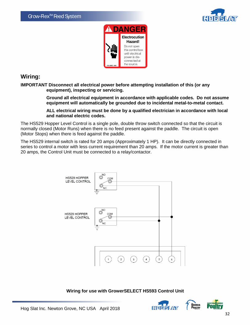
Wiring: IMPORTANT Disconnect all electrical power before attempting installation of this (or any
equipment), inspecting or servicing. Ground all electrical equipment in accordance with applicable codes. Do not assume
equipment will automatically be grounded due to incidental metal-to-metal contact. ALL electrical wiring must be done by a qualified electrician in accordance with local
and national electric codes. The HS529 Hopper Level Control is a single pole, double throw switch connected so that the circuit is normally closed (Motor Runs) when there is no feed present against the paddle. The circuit is open (Motor Stops) when there is feed against the paddle.
The HS529 internal switch is rated for 20 amps (Approximately 1 HP). It can be directly connected in series to control a motor with less current requirement than 20 amps. If the motor current is greater than 20 amps, the Control Unit must be connected to a relay/contactor.
Wiring for use with GrowerSELECT HS593 Control Unit
Hog Slat Inc. Newton Grove, NC USA April 2018 33
Grow-FlexTM Feed System
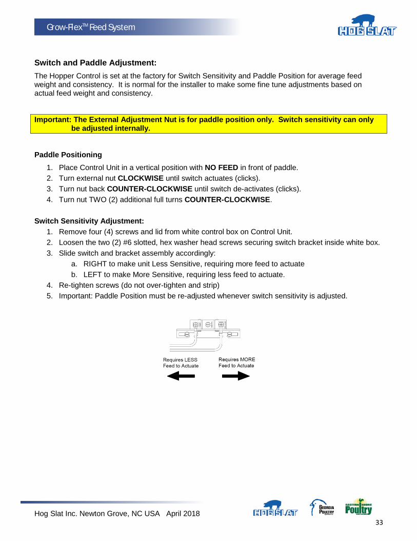
Switch and Paddle Adjustment: The Hopper Control is set at the factory for Switch Sensitivity and Paddle Position for average feed weight and consistency. It is normal for the installer to make some fine tune adjustments based on actual feed weight and consistency.
Important: The External Adjustment Nut is for paddle position only. Switch sensitivity can only be adjusted internally.
Paddle Positioning
1. Place Control Unit in a vertical position with NO FEED in front of paddle. 2. Turn external nut CLOCKWISE until switch actuates (clicks). 3. Turn nut back COUNTER-CLOCKWISE until switch de-activates (clicks). 4. Turn nut TWO (2) additional full turns COUNTER-CLOCKWISE.
Switch Sensitivity Adjustment:
1. Remove four (4) screws and lid from white control box on Control Unit. 2. Loosen the two (2) #6 slotted, hex washer head screws securing switch bracket inside white box. 3. Slide switch and bracket assembly accordingly:
a. RIGHT to make unit Less Sensitive, requiring more feed to actuate b. LEFT to make More Sensitive, requiring less feed to actuate.
4. Re-tighten screws (do not over-tighten and strip) 5. Important: Paddle Position must be re-adjusted whenever switch sensitivity is adjusted.
Hog Slat Inc. Newton Grove, NC USA April 2018 34
Grow-FlexTM Feed System
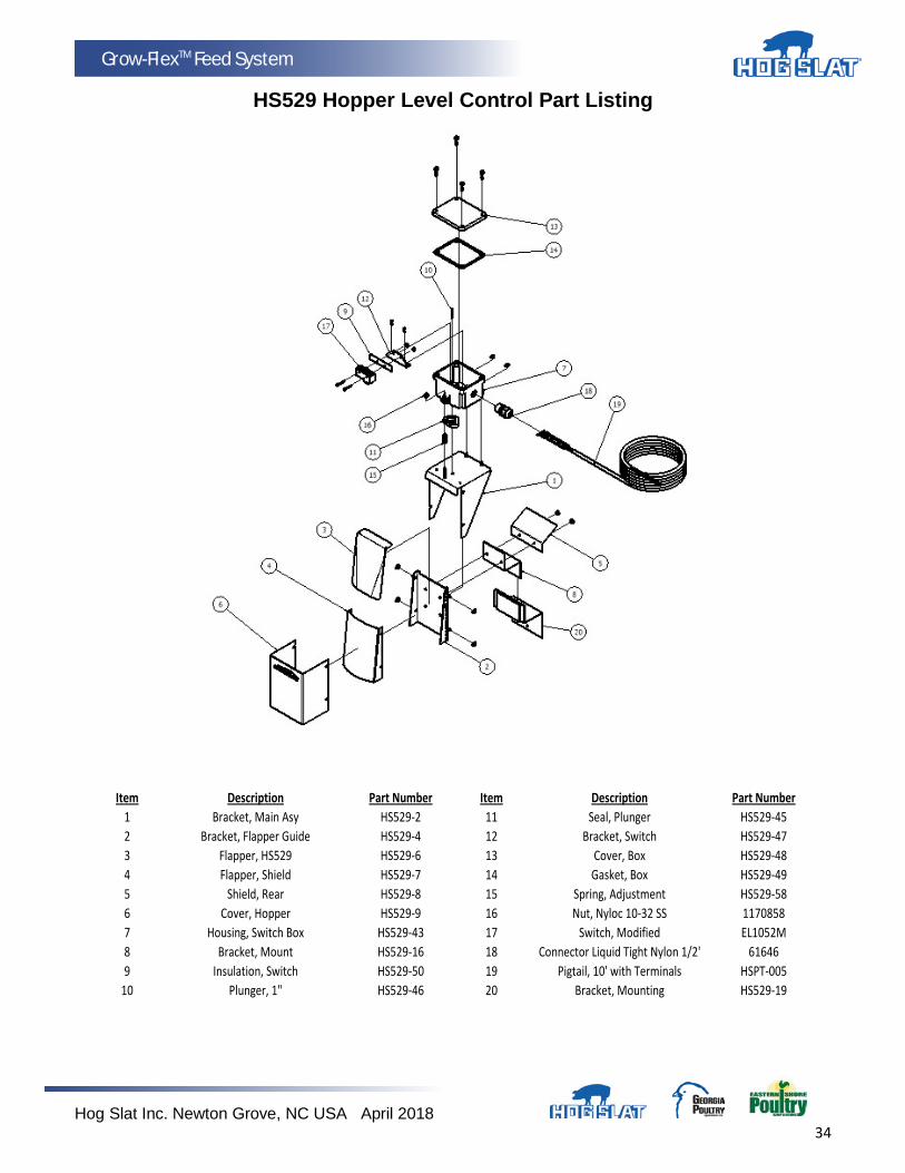
HS529 Hopper Level Control Part Listing
Item Description Part Number Item Description Part Number1 Bracket, Main Asy HS529-2 11 Seal, Plunger HS529-452 Bracket, Flapper Guide HS529-4 12 Bracket, Switch HS529-473 Flapper, HS529 HS529-6 13 Cover, Box HS529-484 Flapper, Shield HS529-7 14 Gasket, Box HS529-495 Shield, Rear HS529-8 15 Spring, Adjustment HS529-586 Cover, Hopper HS529-9 16 Nut, Nyloc 10-32 SS 11708587 Housing, Switch Box HS529-43 17 Switch, Modified EL1052M8 Bracket, Mount HS529-16 18 Connector Liquid Tight Nylon 1/2' 616469 Insulation, Switch HS529-50 19 Pigtail, 10' with Terminals HSPT-005
10 Plunger, 1" HS529-46 20 Bracket, Mounting HS529-19
Hog Slat Inc. Newton Grove, NC USA April 2018 35
Grow-FlexTM Feed System
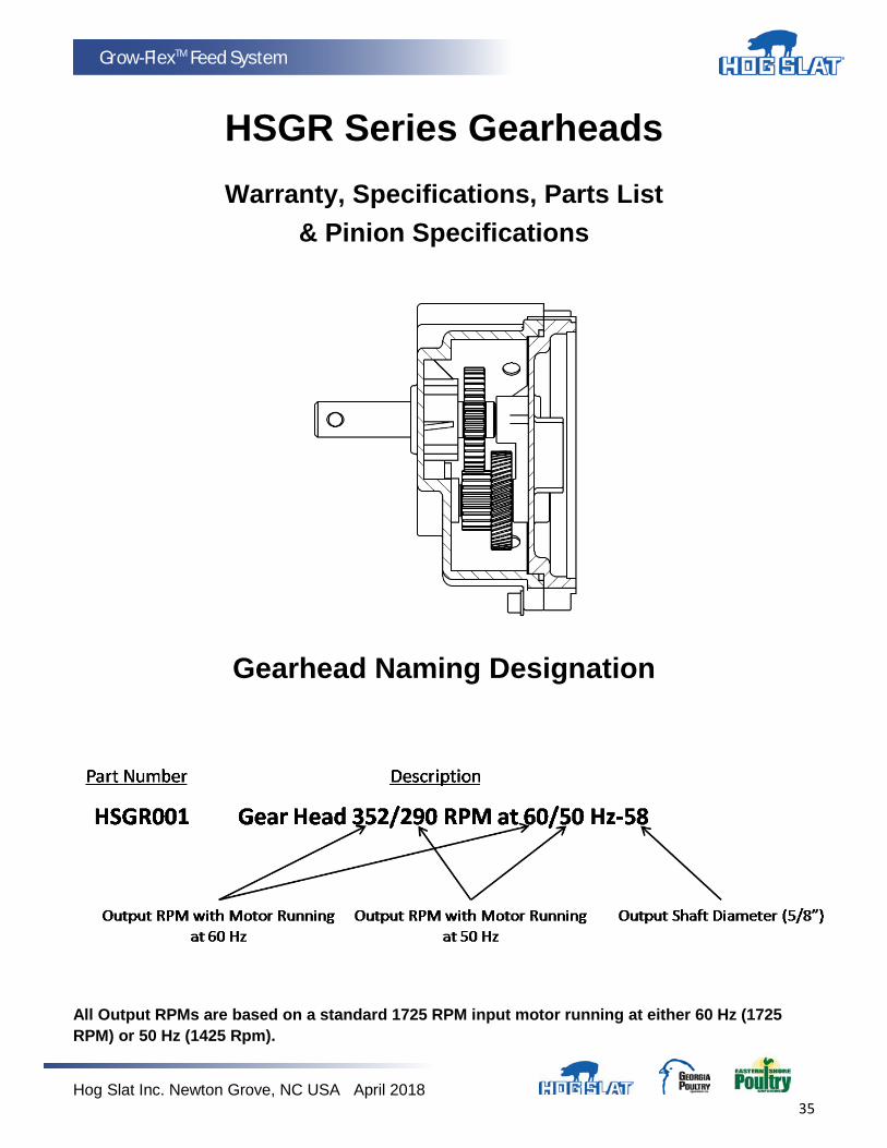
HSGR Series Gearheads
Warranty, Specifications, Parts List & Pinion Specifications
Gearhead Naming Designation
All Output RPMs are based on a standard 1725 RPM input motor running at either 60 Hz (1725 RPM) or 50 Hz (1425 Rpm).
Hog Slat Inc. Newton Grove, NC USA April 2018 36
Grow-FlexTM Feed System
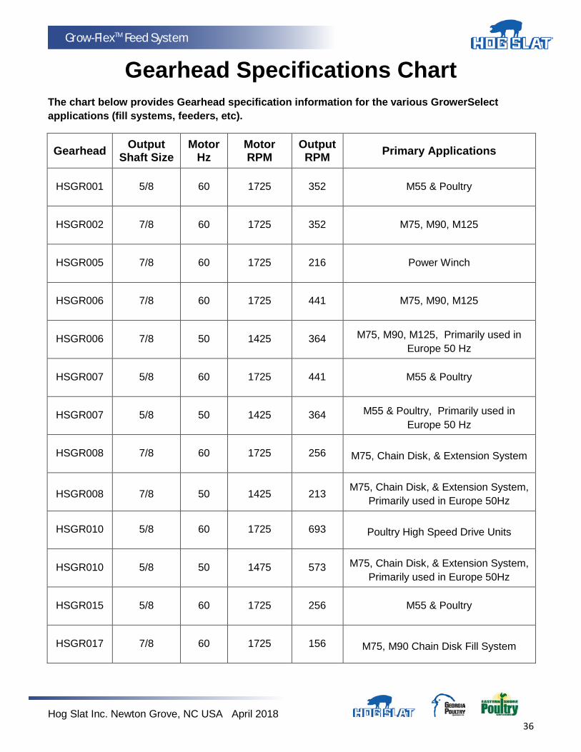
Gearhead Specifications Chart
The chart below provides Gearhead specification information for the various GrowerSelect applications (fill systems, feeders, etc).
Gearhead Output Shaft Size
Motor Hz
Motor RPM
Output RPM Primary Applications
HSGR001 5/8 60 1725 352 M55 & Poultry
HSGR002 7/8 60 1725 352 M75, M90, M125
HSGR005 7/8 60 1725 216 Power Winch
HSGR006 7/8 60 1725 441 M75, M90, M125
HSGR006 7/8 50 1425 364 M75, M90, M125, Primarily used in Europe 50 Hz
HSGR007 5/8 60 1725 441 M55 & Poultry
HSGR007 5/8 50 1425 364 M55 & Poultry, Primarily used in Europe 50 Hz
HSGR008 7/8 60 1725 256 M75, Chain Disk, & Extension System
HSGR008 7/8 50 1425 213 M75, Chain Disk, & Extension System, Primarily used in Europe 50Hz
HSGR010 5/8 60 1725 693 Poultry High Speed Drive Units
HSGR010 5/8 50 1475 573 M75, Chain Disk, & Extension System, Primarily used in Europe 50Hz
HSGR015 5/8 60 1725 256 M55 & Poultry
HSGR017 7/8 60 1725 156 M75, M90 Chain Disk Fill System
Hog Slat Inc. Newton Grove, NC USA April 2018 37
Grow-FlexTM Feed System
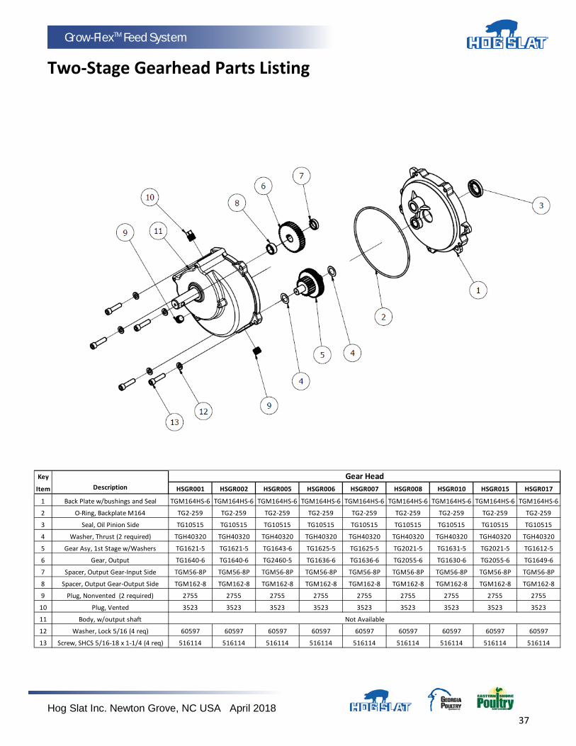
Two-Stage Gearhead Parts Listing
Key
Item Description HSGR001 HSGR002 HSGR005 HSGR006 HSGR007 HSGR008 HSGR010 HSGR015 HSGR017
1 Back Plate w/bushings and Seal TGM164HS-6 TGM164HS-6 TGM164HS-6 TGM164HS-6 TGM164HS-6 TGM164HS-6 TGM164HS-6 TGM164HS-6 TGM164HS-6
2 O-Ring, Backplate M164 TG2-259 TG2-259 TG2-259 TG2-259 TG2-259 TG2-259 TG2-259 TG2-259 TG2-259
3 Seal, Oil Pinion Side TG10515 TG10515 TG10515 TG10515 TG10515 TG10515 TG10515 TG10515 TG10515
4 Washer, Thrust (2 required) TGH40320 TGH40320 TGH40320 TGH40320 TGH40320 TGH40320 TGH40320 TGH40320 TGH40320
5 Gear Asy, 1st Stage w/Washers TG1621-5 TG1621-5 TG1643-6 TG1625-5 TG1625-5 TG2021-5 TG1631-5 TG2021-5 TG1612-5
6 Gear, Output TG1640-6 TG1640-6 TG2460-5 TG1636-6 TG1636-6 TG2055-6 TG1630-6 TG2055-6 TG1649-6
7 Spacer, Output Gear-Input Side TGM56-8P TGM56-8P TGM56-8P TGM56-8P TGM56-8P TGM56-8P TGM56-8P TGM56-8P TGM56-8P
8 Spacer, Output Gear-Output Side TGM162-8 TGM162-8 TGM162-8 TGM162-8 TGM162-8 TGM162-8 TGM162-8 TGM162-8 TGM162-8
9 Plug, Nonvented (2 required) 2755 2755 2755 2755 2755 2755 2755 2755 2755
10 Plug, Vented 3523 3523 3523 3523 3523 3523 3523 3523 3523
11 Body, w/output shaft
12 Washer, Lock 5/16 (4 req) 60597 60597 60597 60597 60597 60597 60597 60597 60597
13 Screw, SHCS 5/16-18 x 1-1/4 (4 req) 516114 516114 516114 516114 516114 516114 516114 516114 516114
Not Available
Gear Head
Hog Slat Inc. Newton Grove, NC USA April 2018 38
Grow-FlexTM Feed System
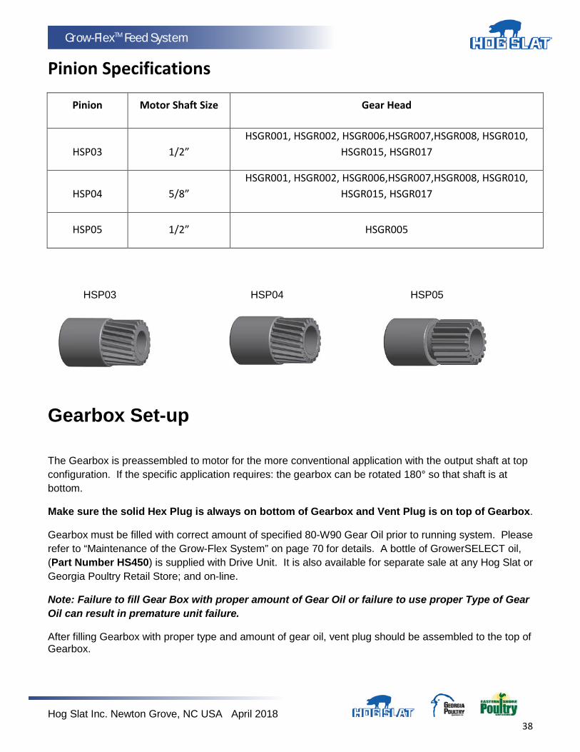
Pinion Specifications
Pinion Motor Shaft Size Gear Head
HSP03 1/2” HSGR001, HSGR002, HSGR006,HSGR007,HSGR008, HSGR010,
HSGR015, HSGR017
HSP04 5/8” HSGR001, HSGR002, HSGR006,HSGR007,HSGR008, HSGR010,
HSGR015, HSGR017
HSP05 1/2” HSGR005
HSP03 HSP04 HSP05
Gearbox Set-up
The Gearbox is preassembled to motor for the more conventional application with the output shaft at top configuration. If the specific application requires: the gearbox can be rotated 180° so that shaft is at bottom.
Make sure the solid Hex Plug is always on bottom of Gearbox and Vent Plug is on top of Gearbox.
Gearbox must be filled with correct amount of specified 80-W90 Gear Oil prior to running system. Please refer to “Maintenance of the Grow-Flex System” on page 70 for details. A bottle of GrowerSELECT oil, (Part Number HS450) is supplied with Drive Unit. It is also available for separate sale at any Hog Slat or Georgia Poultry Retail Store; and on-line.
Note: Failure to fill Gear Box with proper amount of Gear Oil or failure to use proper Type of Gear Oil can result in premature unit failure.
After filling Gearbox with proper type and amount of gear oil, vent plug should be assembled to the top of Gearbox.

Hog Slat Inc. Newton Grove, NC USA April 2018 39
Grow-FlexTM Feed System
Auger Installation & Pre-Tensioning Procedure
Severe personal injury will result, if the electrical power is not disconnected, prior to installation or servicing.
Always wear protective clothing and protective glasses when working with auger. Use extreme caution when working with GROW-FLEX auger. The auger is under tension and may spring back causing severe injury. Keep your hands away from the end of the auger tube to avoid injury when pushing the auger into the auger tubes
Handle the auger very carefully. Dropping the rolls of auger may cause the auger to kink. Do not install an auger that has a kink in it. The kink will cause the auger to wear the tube at that spot. If the kink cannot be straightened with pliers, the kink must be cut out and the auger brazed back together.
Two (2) people are recommended to install the GROW-FLEX auger. One person will feed the auger into the tubing while the other person verifies the auger is not damaged. Make sure no foreign objects enter into the tubing.
1. Beginning at the unloader, push the auger into the auger tube through the rear of the unloader until the auger reaches the control unit at end of the line.
2. Attach the auger to the driver by rotating the driver and threading the auger through the anchor clamp.
Figure 16 shows the Model 55 Driver installation procedure. Control Unit not shown for clarity.
Figure 17 shows the Model 75, 90, & HR Driver installation procedure. Control Unit not shown for clarity.
3. Rotate the auger so that it is fully engaged on the Driver. Tighten the screws securely to clamp the auger to the control unit. See Figure 16 or 17.
Direct Driver Kit includes Tube Direct Driver Kit includes Tube Figure 16. Model 55 Auger Installation (Drive End) Figure 17. Model 75, 90, & HR Auger Installation (Drive End)

Hog Slat Inc. Newton Grove, NC USA April 2018 40
Grow-FlexTM Feed System
4. Cut off auger approximately 6 inches past unloader.
5. Run system without anchor bearing or feed in the line for 15 minutes. After 15 minutes, lock out power to drive unit.
6. Pull on the cut end of the auger at the unloader a couple of times until it begins to stretch and then release it slowly. This will relax the auger to its natural length.
STEPS 5 & 6 ARE IMPORTANT BECAUSE IT WILL ALLOW NEW AUGER TO FIND ITS NATURAL LENGTH PRIOR TO STRETCHING PROCESS.
7. While the auger is relaxed, mark the auger where it exits the unloader. For single bin system, stretch the auger 2 inches for every 50 feet of system length. If it is a tandem system, stretch the auger 4 inches for every 50 feet. Mark and cut the auger at that stretched length.
Note: For ease of cutting, pull the auger an additional 6 to 8 inches from unloader and use locking pliers to secure the auger prior to cutting.
8. With locking pliers still attached, insert auger over the anchor and through the Auger Clamp until auger touches Anchor Bearing.
Figure 18 shows the proper assembly of the Model 55 unloader components. Torque the set screw into Auger Clamp 10-12 ft.-lbs. Over tightening the set screw may cause damage to the Auger Clamp.
Figure 18. Model 55 Anchor and Bearing Installation
1 Anchor Bearing Clamp 2 Anchor Bearing 3 Auger Clamp 4 Screw for securing auger to the anchor 5 Auger 6 Unloader

Hog Slat Inc. Newton Grove, NC USA April 2018 41
Grow-FlexTM Feed System
Figure 19 shows the proper assembly of the Model 75, 90, & HR anchor components. Insert the anchor into the auger until the auger touches the anchor flange. The auger must be threaded onto the Auger Clamp Pin. Tighten the clamp pin set screw on the auger.
Figure 19. Model 75, 90, & HR Anchor and Bearing Assembly
1 Anchor Bearing Clamp 2 Anchor Bearing Assembly 3 Auger Clamp Pin 4 Auger 5 Unloader
Some of the Unloader Models have Anchor and Bearing Assemblies with Restrictors that may be shortened, if necessary, to increase capacity. 9. Carefully remove the locking pliers and attach the Anchor Bearing Assembly to the Unloader with
Anchor Bearing Clamp.
10. Place a HS527 cannonball into the unloader.
11. Follow the GrowerSELECT Grow-Flex Feed Auger Run-in Procedure (see page 47) prior to starting system.

Hog Slat Inc. Newton Grove, NC USA April 2018 42
Grow-FlexTM Feed System
Cover Plate Installation The cover plate is installed after installation of the auger in the tube. See Figure 20. (End View)
To install the cover plate:
1. Loosen wing nuts to end of studs.
2. Start lower side of cover plate in boot opening.
3. Slide the cover plate up as far as possible so that plate catches top of boot opening.
4. Hold the cover securely while tightening the wing nuts.
Hog Slat Inc. Newton Grove, NC USA April 2018 43
Grow-FlexTM Feed System
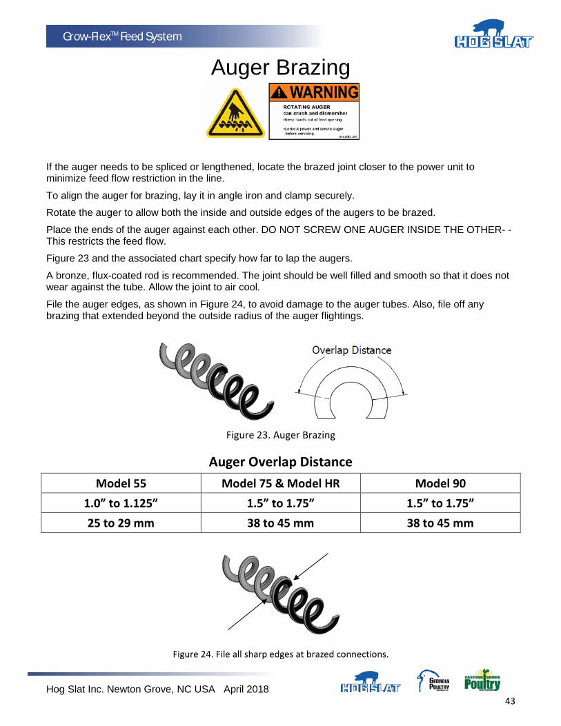
Auger Brazing
If the auger needs to be spliced or lengthened, locate the brazed joint closer to the power unit to minimize feed flow restriction in the line.
To align the auger for brazing, lay it in angle iron and clamp securely.
Rotate the auger to allow both the inside and outside edges of the augers to be brazed.
Place the ends of the auger against each other. DO NOT SCREW ONE AUGER INSIDE THE OTHER- -This restricts the feed flow.
Figure 23 and the associated chart specify how far to lap the augers.
A bronze, flux-coated rod is recommended. The joint should be well filled and smooth so that it does not wear against the tube. Allow the joint to air cool.
File the auger edges, as shown in Figure 24, to avoid damage to the auger tubes. Also, file off any brazing that extended beyond the outside radius of the auger flightings.
Figure 23. Auger Brazing
Auger Overlap Distance Model 55 Model 75 & Model HR Model 90
1.0” to 1.125” 1.5” to 1.75” 1.5” to 1.75” 25 to 29 mm 38 to 45 mm 38 to 45 mm
Figure 24. File all sharp edges at brazed connections.

Hog Slat Inc. Newton Grove, NC USA April 2018 44
Grow-FlexTM Feed System
Restrictor Tube Adjustment Some unloaders have Restrictors that may be adjusted for increased delivery capacities. (See Figure 25) DO NOT ADJUST THE RESTRICTOR UNTIL THE SYSTEM HAS BEEN IN OPERATION AND THE SYSTEM IS BROKEN IN. THE MODEL 55 RESTRICTOR IS NOT ADJUSTABLE.
Note: Feed delivery capacities are based on 40 lbs/ft.³ (640 kg /m³) feed density. Systems using lighter weight feeds may not be able to achieve the maximum capacities listed. Note: Always refer to the motor amperage nameplate when increasing the feed flow capacity. Exceeding the nameplate amperage may result in motor overload tripping and/or damage to the system.
1. Loosen the tube clamp on the back of the unloader to remove the Anchor and Bearing Assembly from the unloader.
2. Use extreme caution when working with the auger under tension. Springing auger can cause personal injury.
3. Pull enough of the auger out of the auger tube to allow the Restrictor Tube to be cut. Use locking pliers to hold the auger outside the boot.
4. Use a hacksaw to cut 1" (25 mm) at a time off the end of the Restrictor Tube to increase feed flow. See Figure 25.
5. CAREFULLY remove the locking pliers while holding on to the Anchor and Bearing Assembly and auger securely.
6. CAREFULLY allow auger to draw the Anchor and Bearing Assembly back into the unloader. DO NOT ALLOW THE BEARING TO BE SLAMMED BACK INTO THE UNLOADER.
Figure 25. Restrictor Tube Adjustment - Models 75, 90, & HR ONLY.
Key Description 1 Restrictor Tube
Cut off approximately 1” (25 mm) of the Restrictor Tube to increase the amount of feed flow. Repeat as required.
Hog Slat Inc. Newton Grove, NC USA April 2018 45
Grow-FlexTM Feed System
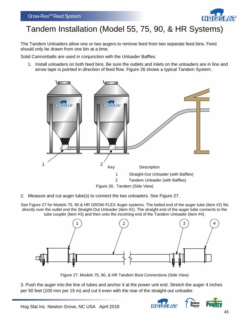
Tandem Installation (Model 55, 75, 90, & HR Systems) The Tandem Unloaders allow one or two augers to remove feed from two separate feed bins. Feed should only be drawn from one bin at a time.
Solid Cannonballs are used in conjunction with the Unloader Baffles.
1. Install unloaders on both feed bins. Be sure the outlets and inlets on the unloaders are in line and arrow tape is pointed in direction of feed flow. Figure 26 shows a typical Tandem System.
Key Description
1 Straight-Out Unloader (with Baffles) 2 Tandem Unloader (with Baffles)
Figure 26. Tandem (Side View)
2. Measure and cut auger tube(s) to connect the two unloaders. See Figure 27.
See Figure 27 for Models 75, 90 & HR GROW-FLEX Auger systems. The belled end of the auger tube (item #2) fits directly over the outlet end the Straight-Out Unloader (item #1). The straight end of the auger tube connects to the
tube coupler (item #3) and then onto the incoming end of the Tandem Unloader (item #4).
Figure 27. Models 75, 90, & HR Tandem Boot Connections (Side View)
3. Push the auger into the line of tubes and anchor it at the power unit end. Stretch the auger 4 inches per 50 feet (100 mm per 15 m) and cut it even with the rear of the straight-out unloader.
1
2
Hog Slat Inc. Newton Grove, NC USA April 2018 46
Grow-FlexTM Feed System
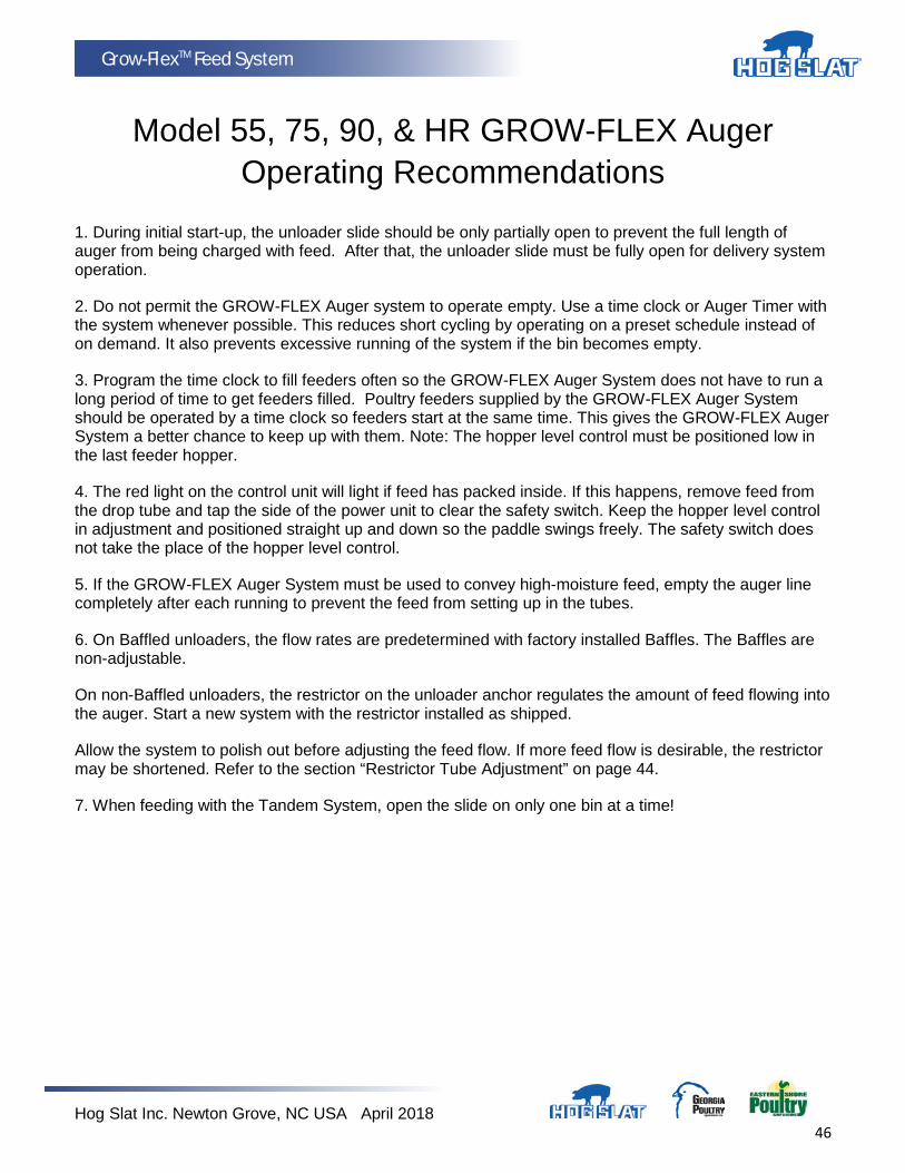
Model 55, 75, 90, & HR GROW-FLEX Auger Operating Recommendations
1. During initial start-up, the unloader slide should be only partially open to prevent the full length of auger from being charged with feed. After that, the unloader slide must be fully open for delivery system operation.
2. Do not permit the GROW-FLEX Auger system to operate empty. Use a time clock or Auger Timer with the system whenever possible. This reduces short cycling by operating on a preset schedule instead of on demand. It also prevents excessive running of the system if the bin becomes empty.
3. Program the time clock to fill feeders often so the GROW-FLEX Auger System does not have to run a long period of time to get feeders filled. Poultry feeders supplied by the GROW-FLEX Auger System should be operated by a time clock so feeders start at the same time. This gives the GROW-FLEX Auger System a better chance to keep up with them. Note: The hopper level control must be positioned low in the last feeder hopper.
4. The red light on the control unit will light if feed has packed inside. If this happens, remove feed from the drop tube and tap the side of the power unit to clear the safety switch. Keep the hopper level control in adjustment and positioned straight up and down so the paddle swings freely. The safety switch does not take the place of the hopper level control.
5. If the GROW-FLEX Auger System must be used to convey high-moisture feed, empty the auger line completely after each running to prevent the feed from setting up in the tubes.
6. On Baffled unloaders, the flow rates are predetermined with factory installed Baffles. The Baffles are non-adjustable.
On non-Baffled unloaders, the restrictor on the unloader anchor regulates the amount of feed flowing into the auger. Start a new system with the restrictor installed as shipped.
Allow the system to polish out before adjusting the feed flow. If more feed flow is desirable, the restrictor may be shortened. Refer to the section “Restrictor Tube Adjustment” on page 44.
7. When feeding with the Tandem System, open the slide on only one bin at a time!

Hog Slat Inc. Newton Grove, NC USA April 2018 47
Grow-FlexTM Feed System
Auger Run-in Procedure
All installations of Hog Slat’s Grow-Flex Auger should be Run-in using the following procedure. This procedure applies to new installations as well as just auger replacement in existing auger tubing. This also assumes that the recommended auger pretension procedure is complete.
1. Close the slide on the unloader.
2. Run the system dry for 15 - 30 minutes. While the system is running, close all drops except for the one furthest from the feed bin.
3. After dry run-in, leave the system running while slowly opening the slide 1” to 1-1/2”. Allow feed to enter the system for 1 minute (approximately 50 pounds of feed), and then close the slide.
4. Go to the last drop and wait for all the feed in the line to exit the system.
5. Repeat steps 3 and 4 three additional times until feed is clean and dry.
This process removes the manufacturing grease and oil from auger and tubes. Failure to completely remove grease and oil will result in excessive feed build up causing auger to plug and bind.
6. At this point the auger system is ready to be run normally, with the slide in the fully open position.

Hog Slat Inc. Newton Grove, NC USA April 2018 48
Grow-FlexTM Feed System
Model 55, 75, 90, & HR GROW-FLEX Auger Feed Delivery System Line Components
Standard Components
Model 55 Model 75 Model 90 Model HR KEY DESCRIPTION PART NO. PART NO. PART NO. PART NO.
1 Boot See separate Standard Grow-Flex Boots
2 Unloader Assembly See separate Unloader Kit Components
3 PVC Auger Tube HSAT55-S HSAT75-S HSAT90-S HSAT90-S
4 PVC Tube Coupler HSAT55-C HSAT75-C HSAT90-C HSAT90-C
5 45 Degree PVC Elbow HSAT55-45 HSAT75-45 HSAT90-45 HSAT90-45
6 GROW-FLEX Auger HSFA-55 HSFA-75 HSFA-90 HSFA-75
7 Cup Hooks 60665 60665 60665 60665
8 Tube Clamp 60399 60399 60399 60399
9 Kwik-Attach Drop Kit HS655 HS675 HS690 HS690
10 Wire Pin 60638 60638 60638 60638
11 Drop Tube HSDT002 HSDT002 HSDT003 HSDT003
12 Control Unit HS593 HS593 HS593 HS593
13 Direct Driver & Tube Anchor HS536 HS531 HS537 HS540
14 Direct Drive Power Units See separate parts list
15 Extension Unloader HS566KITA HS520KITA HS557KITA HS557KITA
Hog Slat Inc. Newton Grove, NC USA April 2018 49
Grow-FlexTM Feed System
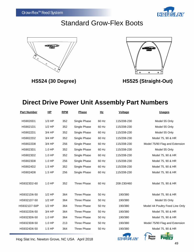
Standard Grow-Flex Boots
HS524 (30 Degree) HS525 (Straight-Out) Direct Drive Power Unit Assembly Part Numbers Part Number HP RPM Phase Hz Voltage Usages
HS9020D1 1/3 HP 352 Single Phase 60 Hz 115/208-230 Model 55 Only
HS9021D1 1/2 HP 352 Single Phase 60 Hz 115/208-230 Model 55 Only
HS9022D1 3/4 HP 352 Single Phase 60 Hz 115/208-230 Model 55 Only
HS9022D2 3/4 HP 352 Single Phase 60 Hz 115/208-230 Model 75, 90 & HR
HS9022D8 3/4 HP 256 Single Phase 60 Hz 115/208-230 Model 75/90 Flag and Extension
HS9023D1 1.0 HP 352 Single Phase 60 Hz 115/208-230 Model 55 Only
HS9023D2 1.0 HP 352 Single Phase 60 Hz 115/208-230 Model 75, 90 & HR
HS9023D8 1.0 HP 256 Single Phase 60 Hz 115/208-230 Model 75, 90 & HR
HS9024D2 1.5 HP 352 Single Phase 60 Hz 115/208-230 Model 75, 90 & HR
HS9024D8 1.5 HP 256 Single Phase 60 Hz 115/208-230 Model 75, 90 & HR
HS9323D2-60 1.0 HP 352 Three Phase 60 Hz 208-230/460 Model 75, 90 & HR
HS9321D6-50 1/2 HP 364 Three Phase 50 Hz 190/380 Model 75, 90 & HR
HS9321D7-50 1/2 HP 364 Three Phase 50 Hz 190/380 Model 55 Only
HS9321D7-50P 1/2 HP 364 Three Phase 50 Hz 190/380 Model 44 Poultry Feed Line Only
HS9322D6-50 3/4 HP 364 Three Phase 50 Hz 190/380 Model 75, 90 & HR
HS9323D6-50 1.0 HP 364 Three Phase 50 Hz 190/380 Model 75, 90 & HR
HS9323D8-50 1.0 HP 213 Three Phase 50 Hz 190/380 Model 75/90 Flag and Extension
HS9324D6-50 1.5 HP 364 Three Phase 50 Hz 190/380 Model 75, 90 & HR

Hog Slat Inc. Newton Grove, NC USA April 2018 50
Grow-FlexTM Feed System
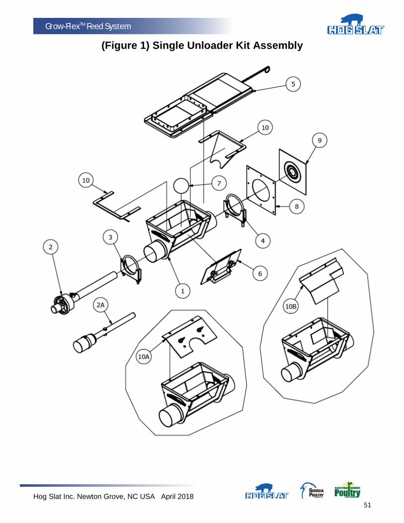
Single Unloader Kit Components (See Figure 1 For Diagram)
Item Description Model 55 Model 75 Model 90 Model HR
Unloader Assembly HS556KIT HS520KIT HS557KIT HS557HRKIT
1 Single Unloader Weldment HS556 HS520 HS557 HS557
2 Anchor Bearing - - - - HSAB75C HSAB90U HSAB90U-HR
2A Anchor Bearing HSAB55C - - - - - - - - - - - -
*2B Cap HSAB55-13 HSAB75-11 HSAB75-11 HSAB75-11
*2C Clamp with Screw HSAB55-21 HSAB75-14 HSAB75-14 HSAB75-14
3 Anchor Bearing Clamp CLAMP200 CLAMP275 CLAMP350 CLAMP350
4 Tube Clamp CLAMP225 CLAMP325 CLAMP400 CLAMP400
5 Transfer Plate & Slide Assembly HS523 HS523 HS523 HS523
**5A Slide Only 8050690700 8050690700 8050690700 8050690700
6 Access Cover for Boot Weldment HS526 HS526 HS526 HS526
7 Cannonball HS527 HS527 HS527 HS527
8 Seal Ring 8120650700 8120650700 8120650700 8120650700
9 Neoprene Seal HS528 HS528 HS528 HS528
10 Baffle - - - - - - - - - - - - HS557-12
10A Baffle - - - - - - - - HS557-7 - - - -
10B Baffle - - - - 8120670700 - - - - - - - -
*Items 2B & 2C are components of items 2 and 2A and each can be ordered separately. (Not shown)
**Item 5A is a component of item 5 and can be ordered separately. (Not shown)
Hog Slat Inc. Newton Grove, NC USA April 2018 51
Grow-FlexTM Feed System
(Figure 1) Single Unloader Kit Assembly
Hog Slat Inc. Newton Grove, NC USA April 2018 52
Grow-FlexTM Feed System
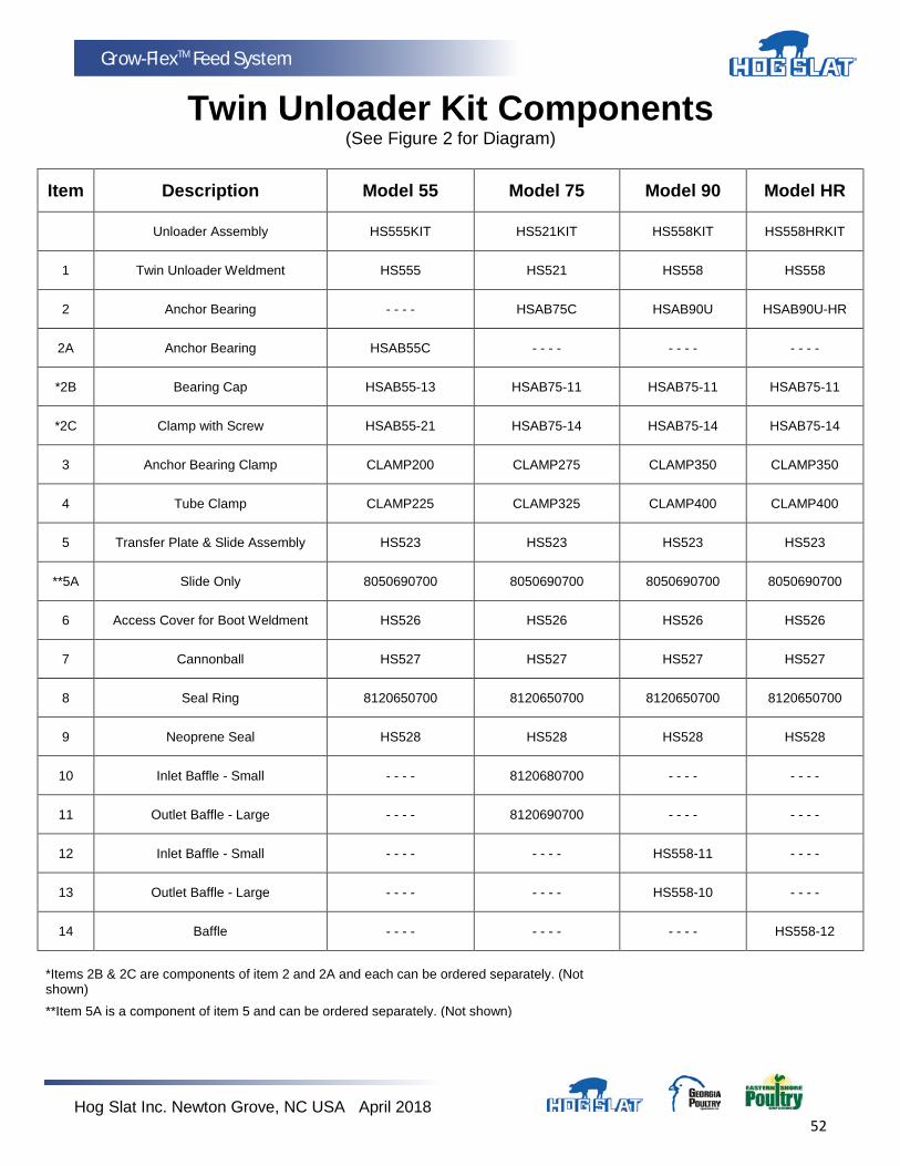
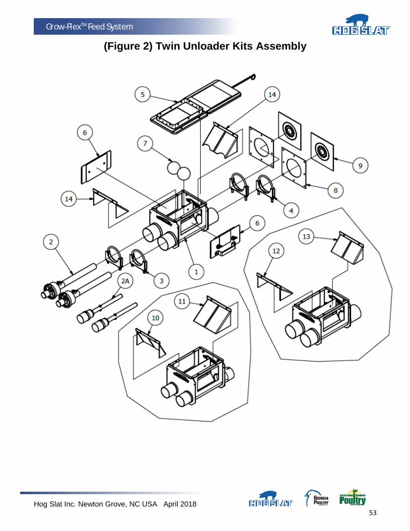
Twin Unloader Kit Components (See Figure 2 for Diagram)
Item Description Model 55 Model 75 Model 90 Model HR
Unloader Assembly HS555KIT HS521KIT HS558KIT HS558HRKIT
1 Twin Unloader Weldment HS555 HS521 HS558 HS558
2 Anchor Bearing - - - - HSAB75C HSAB90U HSAB90U-HR
2A Anchor Bearing HSAB55C - - - - - - - - - - - -
*2B Bearing Cap HSAB55-13 HSAB75-11 HSAB75-11 HSAB75-11
*2C Clamp with Screw HSAB55-21 HSAB75-14 HSAB75-14 HSAB75-14
3 Anchor Bearing Clamp CLAMP200 CLAMP275 CLAMP350 CLAMP350
4 Tube Clamp CLAMP225 CLAMP325 CLAMP400 CLAMP400
5 Transfer Plate & Slide Assembly HS523 HS523 HS523 HS523
**5A Slide Only 8050690700 8050690700 8050690700 8050690700
6 Access Cover for Boot Weldment HS526 HS526 HS526 HS526
7 Cannonball HS527 HS527 HS527 HS527
8 Seal Ring 8120650700 8120650700 8120650700 8120650700
9 Neoprene Seal HS528 HS528 HS528 HS528
10 Inlet Baffle - Small - - - - 8120680700 - - - - - - - -
11 Outlet Baffle - Large - - - - 8120690700 - - - - - - - -
12 Inlet Baffle - Small - - - - - - - - HS558-11 - - - -
13 Outlet Baffle - Large - - - - - - - - HS558-10 - - - -
14 Baffle - - - - - - - - - - - - HS558-12
*Items 2B & 2C are components of item 2 and 2A and each can be ordered separately. (Not shown)
**Item 5A is a component of item 5 and can be ordered separately. (Not shown)
Hog Slat Inc. Newton Grove, NC USA April 2018 53
Grow-FlexTM Feed System
(Figure 2) Twin Unloader Kits Assembly
Hog Slat Inc. Newton Grove, NC USA April 2018 54
Grow-FlexTM Feed System
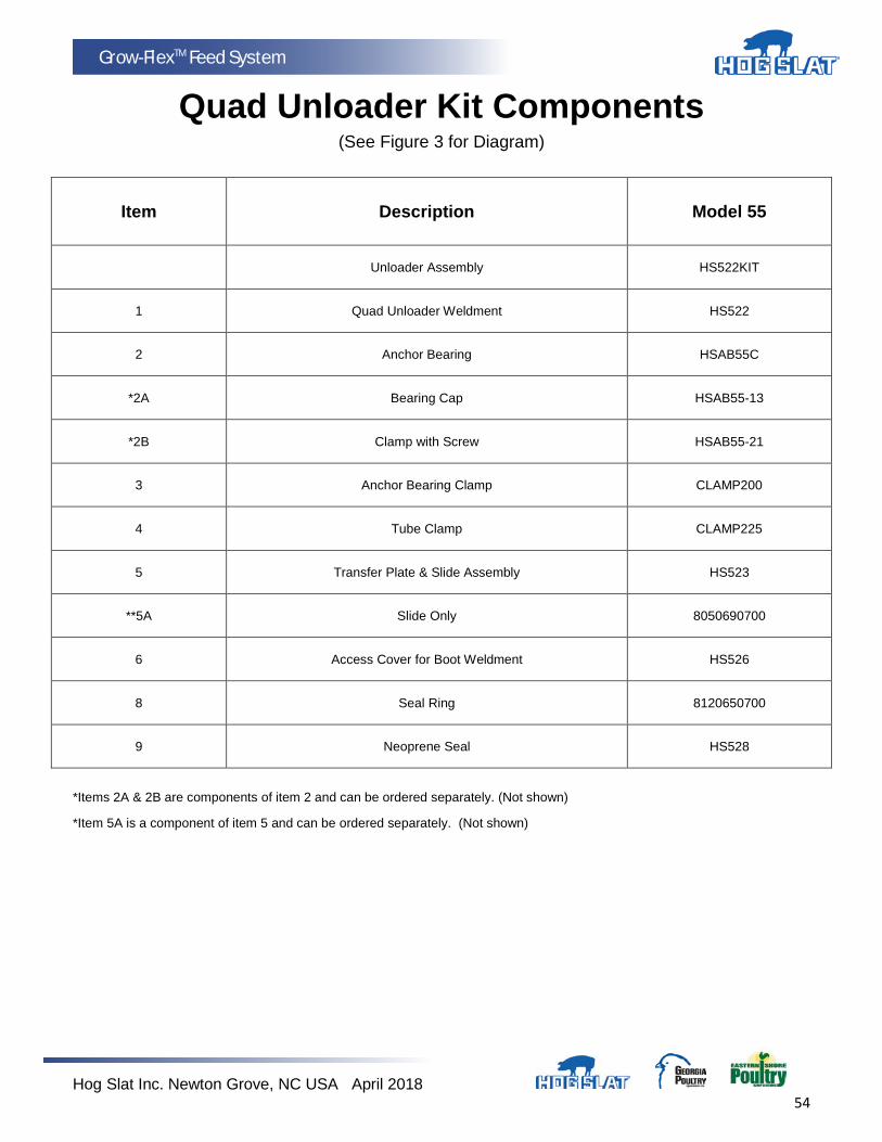
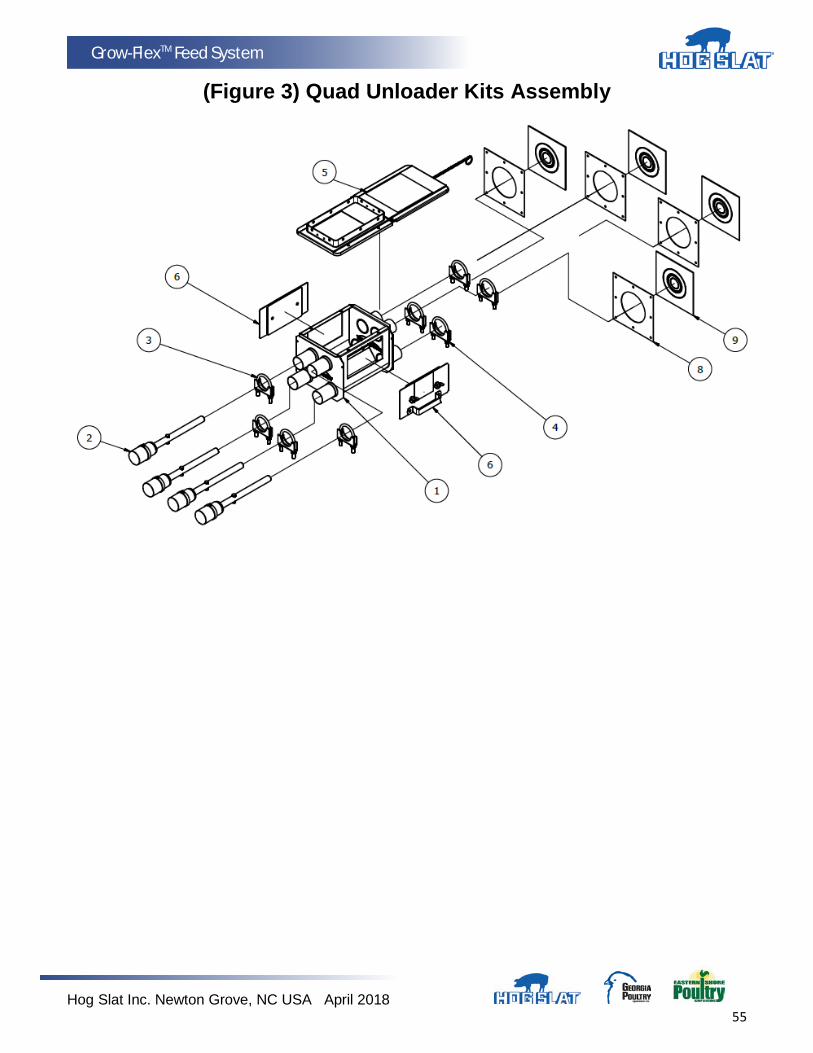
Quad Unloader Kit Components (See Figure 3 for Diagram)
Item Description Model 55
Unloader Assembly HS522KIT
1 Quad Unloader Weldment HS522
2 Anchor Bearing HSAB55C
*2A Bearing Cap HSAB55-13
*2B Clamp with Screw HSAB55-21
3 Anchor Bearing Clamp CLAMP200
4 Tube Clamp CLAMP225
5 Transfer Plate & Slide Assembly HS523
**5A Slide Only 8050690700
6 Access Cover for Boot Weldment HS526
8 Seal Ring 8120650700
9 Neoprene Seal HS528
*Items 2A & 2B are components of item 2 and can be ordered separately. (Not shown)
*Item 5A is a component of item 5 and can be ordered separately. (Not shown)
Hog Slat Inc. Newton Grove, NC USA April 2018 55
Grow-FlexTM Feed System
(Figure 3) Quad Unloader Kits Assembly

Hog Slat Inc. Newton Grove, NC USA April 2018 56
Grow-FlexTM Feed System
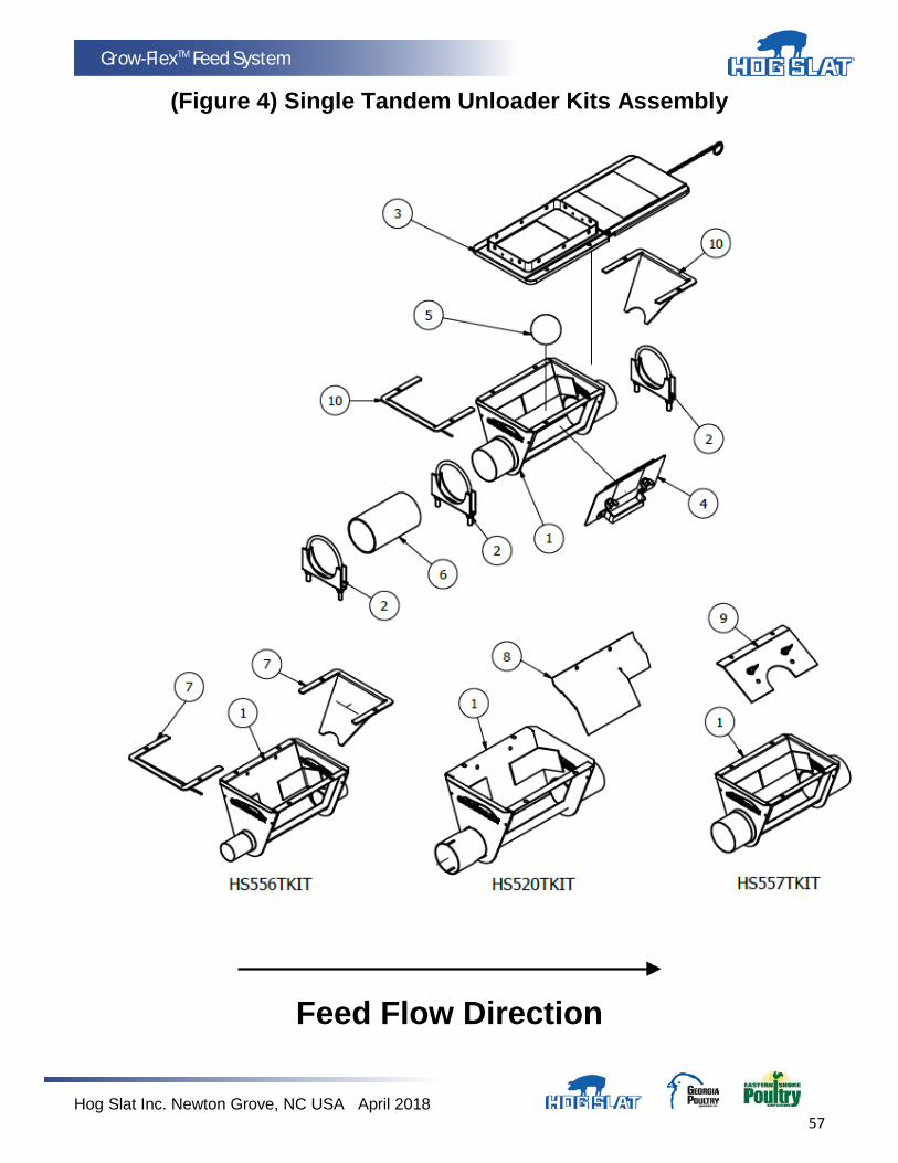
Single Tandem Unloader Kit Components (See Figure 4 for Diagram)
Item Description Model 55 Model 75 Model 90 Model HR
Unloader Assembly HS556TKIT HS520TKIT HS557TKIT HS557HRTKIT
1 Single Unloader Weldment HS556 HS520T HS557 HS557
2 Tube Clamp CLAMP225 CLAMP325 CLAMP400 CLAMP400
3 Transfer Plate & Slide Assembly HS523 HS523 HS523 HS523
*3A Slide Only 8050690700 8050690700 8050690700 8050690700
4 Access Cover for Boot Weldment HS526 HS526 HS526 HS526
5 Cannonball HS527 HS527 HS527 HS527
6 Tube Coupler - - - - HSAT75-C HSAT90-C HSAT90-C
7 Baffle HS557-11 - - - - - - - - - - - -
8 Baffle - - - - 8120670700 - - - - - - - -
9 Baffle - - - - - - - - HS557-7 - - - -
10 Baffle - - - - - - - - - - - - HS557-12
Item 3A is a component of item 3 and can be ordered separately. (Not shown)
Hog Slat Inc. Newton Grove, NC USA April 2018 57
Grow-FlexTM Feed System
(Figure 4) Single Tandem Unloader Kits Assembly
Feed Flow Direction
Hog Slat Inc. Newton Grove, NC USA April 2018 58
Grow-FlexTM Feed System
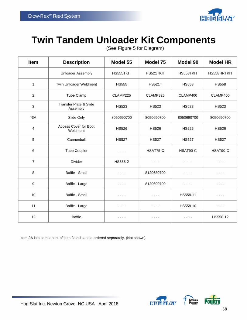
Twin Tandem Unloader Kit Components
(See Figure 5 for Diagram)
Item Description Model 55 Model 75 Model 90 Model HR
Unloader Assembly HS555TKIT HS521TKIT HS558TKIT HS558HRTKIT
1 Twin Unloader Weldment HS555 HS521T HS558 HS558
2 Tube Clamp CLAMP225 CLAMP325 CLAMP400 CLAMP400
3 Transfer Plate & Slide Assembly HS523 HS523 HS523 HS523
*3A Slide Only 8050690700 8050690700 8050690700 8050690700
4 Access Cover for Boot Weldment HS526 HS526 HS526 HS526
5 Cannonball HS527 HS527 HS527 HS527
6 Tube Coupler - - - - HSAT75-C HSAT90-C HSAT90-C
7 Divider HS555-2 - - - - - - - - - - - -
8 Baffle - Small - - - - 8120680700 - - - - - - - -
9 Baffle - Large - - - - 8120690700 - - - - - - - -
10 Baffle - Small - - - - - - - - HS558-11 - - - -
11 Baffle - Large - - - - - - - - HS558-10 - - - -
12 Baffle - - - - - - - - - - - - HS558-12
Item 3A is a component of item 3 and can be ordered separately. (Not shown)
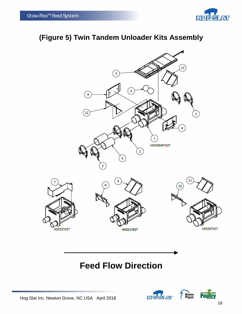
Hog Slat Inc. Newton Grove, NC USA April 2018 59
Grow-FlexTM Feed System
(Figure 5) Twin Tandem Unloader Kits Assembly
Feed Flow Direction
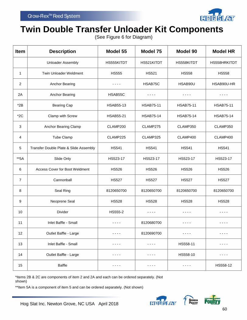
Hog Slat Inc. Newton Grove, NC USA April 2018 60
Grow-FlexTM Feed System
Twin Double Transfer Unloader Kit Components (See Figure 6 for Diagram)
Item Description Model 55 Model 75 Model 90 Model HR
Unloader Assembly HS555KITDT HS521KITDT HS558KITDT HS558HRKITDT
1 Twin Unloader Weldment HS555 HS521 HS558 HS558
2 Anchor Bearing - - - - HSAB75C HSAB90U HSAB90U-HR
2A Anchor Bearing HSAB55C - - - - - - - - - - - -
*2B Bearing Cap HSAB55-13 HSAB75-11 HSAB75-11 HSAB75-11
*2C Clamp with Screw HSAB55-21 HSAB75-14 HSAB75-14 HSAB75-14
3 Anchor Bearing Clamp CLAMP200 CLAMP275 CLAMP350 CLAMP350
4 Tube Clamp CLAMP225 CLAMP325 CLAMP400 CLAMP400
5 Transfer Double Plate & Slide Assembly HS541 HS541 HS541 HS541
**5A Slide Only HS523-17 HS523-17 HS523-17 HS523-17
6 Access Cover for Boot Weldment HS526 HS526 HS526 HS526
7 Cannonball HS527 HS527 HS527 HS527
8 Seal Ring 8120650700 8120650700 8120650700 8120650700
9 Neoprene Seal HS528 HS528 HS528 HS528
10 Divider HS555-2 - - - - - - - - - - - -
11 Inlet Baffle - Small - - - - 8120680700 - - - - - - - -
12 Outlet Baffle - Large - - - - 8120690700 - - - - - - - -
13 Inlet Baffle - Small - - - - - - - - HS558-11 - - - -
14 Outlet Baffle - Large - - - - - - - - HS558-10 - - - -
15 Baffle - - - - - - - - - - - - HS558-12
*Items 2B & 2C are components of item 2 and 2A and each can be ordered separately. (Not shown)
**Item 5A is a component of item 5 and can be ordered separately. (Not shown)
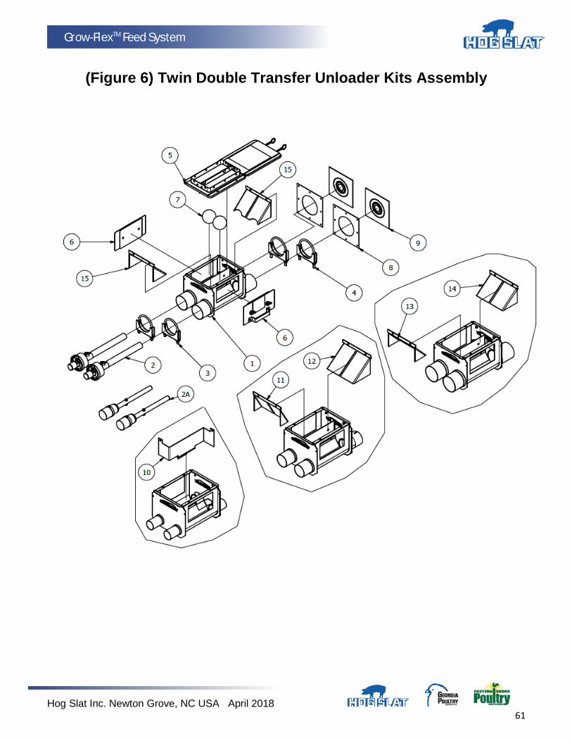
Hog Slat Inc. Newton Grove, NC USA April 2018 61
Grow-FlexTM Feed System
(Figure 6) Twin Double Transfer Unloader Kits Assembly
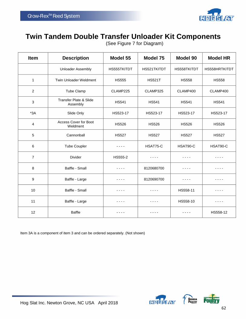
Hog Slat Inc. Newton Grove, NC USA April 2018 62
Grow-FlexTM Feed System
Twin Tandem Double Transfer Unloader Kit Components
(See Figure 7 for Diagram)
Item Description Model 55 Model 75 Model 90 Model HR
Unloader Assembly HS555TKITDT HS521TKITDT HS558TKITDT HS558HRTKITDT
1 Twin Unloader Weldment HS555 HS521T HS558 HS558
2 Tube Clamp CLAMP225 CLAMP325 CLAMP400 CLAMP400
3 Transfer Plate & Slide Assembly HS541 HS541 HS541 HS541
*3A Slide Only HS523-17 HS523-17 HS523-17 HS523-17
4 Access Cover for Boot Weldment HS526 HS526 HS526 HS526
5 Cannonball HS527 HS527 HS527 HS527
6 Tube Coupler - - - - HSAT75-C HSAT90-C HSAT90-C
7 Divider HS555-2 - - - - - - - - - - - -
8 Baffle - Small - - - - 8120680700 - - - - - - - -
9 Baffle - Large - - - - 8120690700 - - - - - - - -
10 Baffle - Small - - - - - - - - HS558-11 - - - -
11 Baffle - Large - - - - - - - - HS558-10 - - - -
12 Baffle - - - - - - - - - - - - HS558-12
Item 3A is a component of item 3 and can be ordered separately. (Not shown)
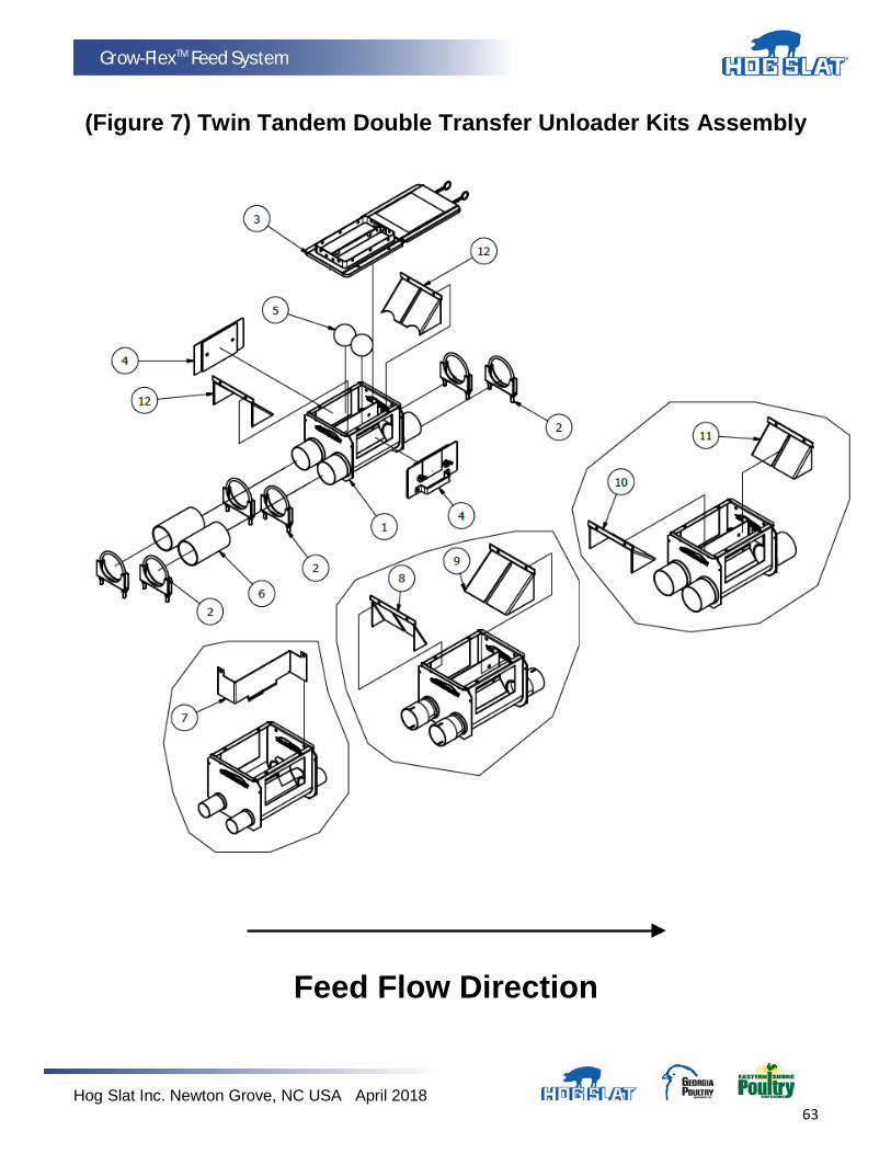
Hog Slat Inc. Newton Grove, NC USA April 2018 63
Grow-FlexTM Feed System
(Figure 7) Twin Tandem Double Transfer Unloader Kits Assembly
Feed Flow Direction

Hog Slat Inc. Newton Grove, NC USA April 2018 64
Grow-FlexTM Feed System
Single Unloader Kit Components With Control Unit Adapter, Drop Kit, &
Control Unit Without Electrical Box (See Figure 8 for Diagram)
Item Description Model 55 Model 75 Model 90
Unloader Assembly HS556KITA HS520KITA HS557KITA
1 Single Unloader Weldment HS556 HS520 HS557
2 Anchor Bearing - - - - HSAB75C HSAB90U
2A Anchor Bearing HSAB55C - - - - - - - -
*2B Cap HSAB55-13 HSAB75-11 HSAB75-11
*2C Clamp with Screw HSAB55-21 HSAB75-14 HSAB75-14
3 Anchor Bearing Clamp CLAMP200 CLAMP275 CLAMP350
4 Tube Clamp CLAMP225 CLAMP325 CLAMP400
5 Access Cover for Boot Weldment HS526 HS526 HS526
6 Cannonball HS527 HS527 HS527
7 Control Unit Adapter HS559 HS559 HS559
8 Drop Adapter Plate Only – 2.9” & 3.5” HS559-6 HS559-6 HS559-6
**9 Control Unit Without Electrical Box - - - - HS611 - - - -
*Items 2B & 2C are components of items 2 and 2A and each can be ordered separately. (Not shown)
**Item 9 includes all components as shown
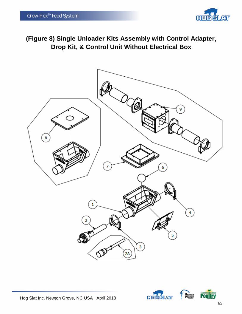
Hog Slat Inc. Newton Grove, NC USA April 2018 65
Grow-FlexTM Feed System
(Figure 8) Single Unloader Kits Assembly with Control Adapter, Drop Kit, & Control Unit Without Electrical Box

Hog Slat Inc. Newton Grove, NC USA April 2018 66
Grow-FlexTM Feed System
Bi-Directional Twin Unloader
(See Figure 9 for Diagram)
Item Description Model 75
Unloader Assembly HS545KIT
1 Twin Unloader Weldment HS545
2 Anchor Bearing HSAB75C
*2A Bearing Cap HSAB75-11
*2B Clamp with Screw HSAB75-14
3 Anchor Bearing Clamp CLAMP350
4 Tube Clamp CLAMP400
5 Transfer Plate & Slide Assembly HS523
**5A Slide Only 8050690700
6 Access Cover for Boot Weldment HS526
7 Cannonball HS527
8 Seal Ring 8120650700
9 Neoprene Seal HS528
10 Baffle - Small 8120680700
*Item 2A & 2B are components of item 2 and can be ordered separately. (Not shown)
**Item 5A is a component of item 5 and can be ordered separately. (Not shown)
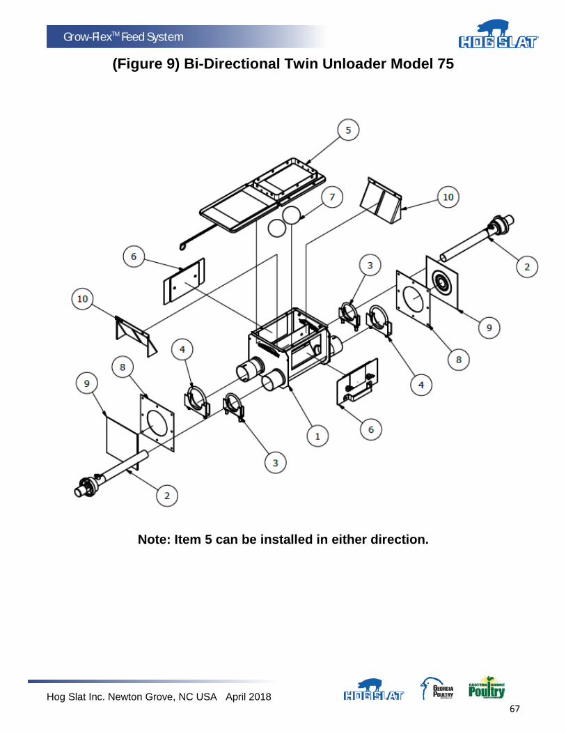
Hog Slat Inc. Newton Grove, NC USA April 2018 67
Grow-FlexTM Feed System
(Figure 9) Bi-Directional Twin Unloader Model 75
Note: Item 5 can be installed in either direction.
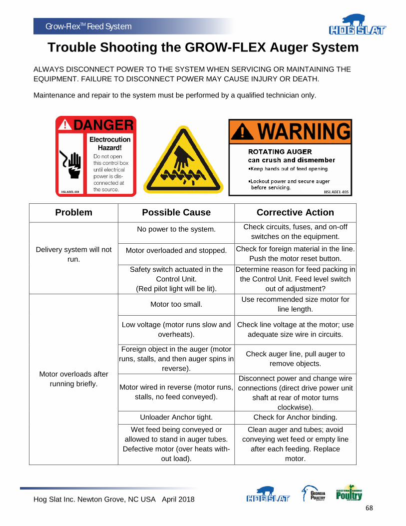
Hog Slat Inc. Newton Grove, NC USA April 2018 68
Grow-FlexTM Feed System
Trouble Shooting the GROW-FLEX Auger System
ALWAYS DISCONNECT POWER TO THE SYSTEM WHEN SERVICING OR MAINTAINING THE EQUIPMENT. FAILURE TO DISCONNECT POWER MAY CAUSE INJURY OR DEATH.
Maintenance and repair to the system must be performed by a qualified technician only.
Problem Possible Cause Corrective Action
Delivery system will not run.
No power to the system. Check circuits, fuses, and on-off switches on the equipment.
Motor overloaded and stopped. Check for foreign material in the line. Push the motor reset button.
Safety switch actuated in the Control Unit.
(Red pilot light will be lit).
Determine reason for feed packing in the Control Unit. Feed level switch
out of adjustment?
Motor overloads after running briefly.
Motor too small. Use recommended size motor for line length.
Low voltage (motor runs slow and overheats).
Check line voltage at the motor; use adequate size wire in circuits.
Foreign object in the auger (motor runs, stalls, and then auger spins in
reverse).
Check auger line, pull auger to remove objects.
Motor wired in reverse (motor runs, stalls, no feed conveyed).
Disconnect power and change wire connections (direct drive power unit
shaft at rear of motor turns clockwise).
Unloader Anchor tight. Check for Anchor binding.
Wet feed being conveyed or allowed to stand in auger tubes. Defective motor (over heats with-
out load).
Clean auger and tubes; avoid conveying wet feed or empty line
after each feeding. Replace motor.

Hog Slat Inc. Newton Grove, NC USA April 2018 69
Grow-FlexTM Feed System
Problem Possible Cause Corrective Action
Motor runs, but auger does not turn.
Sheared driver bolt at Control Unit. Replace driver bolt.
Broken power unit pinion. Examine pinion on motor shaft;
replace BOTH gear head and pinion if pinion is damaged.
Auger wears holes in tubes. Auger kinked or poorly brazed. See Auger Brazing section in this manual
Elbows wear out. Auger is stretched too tight;
horizontal L.H. turn; auger has been running dry.
Lengthen auger; Install an Extension Hopper.
Excessive auger vibration and noise.
System has been operated too often without feed (auger has scored the
auger tubes).
Replace damaged auger tubes; be sure auger has proper amount of
stretch.
Tubes inadequately supported. Support the tubes every 5’ (1.5 m) or closer.
Horizontal L.H. turn. No outlet drops on or just before an elbow; lengthen the auger; install an Extension Hopper ahead of elbows.
Fill system short cycles. Control end feed level switch does
not provide large enough feed differential.
Use a time clock to program operating cycles. Use Control end
feed level switch w/lockout and time clock.
Extension Hopper packs full of feed.
Both switches on Extension Hopper are out of adjustment.
Adjust switches as specified in maintenance section in this manual.
Second portion of extended length system will not start.
Lower switch on Extension Hopper out of adjustment.
Adjust switch as specified in the maintenance section of this manual.
Feed level control at end of line out of adjustment.
Examine and make necessary adjustments; see feed level switch
adjustment instruction.
Second portion of extended length system short cycles.
Too much Restrictor in the Boot. Shorten Restrictor.
Too much feed is still dispensing from drops ahead of Extension
Hopper.
Last outlet drop before Extension Hopper must have full feed drop out. NOTE: All feeders ahead of hopper
must complete filling before feed reaches hopper.
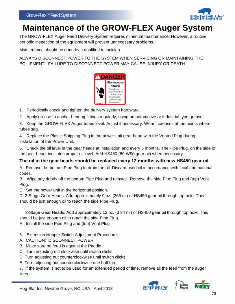
Hog Slat Inc. Newton Grove, NC USA April 2018 70
Grow-FlexTM Feed System
Maintenance of the GROW-FLEX Auger System The GROW-FLEX Auger Feed Delivery System requires minimum maintenance. However, a routine periodic inspection of the equipment will prevent unnecessary problems.
Maintenance should be done by a qualified technician. ALWAYS DISCONNECT POWER TO THE SYSTEM WHEN SERVICING OR MAINTAINING THE EQUIPMENT. FAILURE TO DISCONNECT POWER MAY CAUSE INJURY OR DEATH.
1. Periodically check and tighten the delivery system hardware. 2. Apply grease to anchor bearing fittings regularly, using an automotive or industrial type grease. 3. Keep the GROW-FLEX Auger tubes level. Adjust if necessary. Wear increases at the points where tubes sag. 4. Replace the Plastic Shipping Plug in the power unit gear head with the Vented Plug during installation of the Power Unit. 5. Check the oil level in the gear heads at installation and every 6 months. The Pipe Plug, on the side of the gear head, indicates proper oil level. Add HS450 (80-W90 gear oil) when necessary.
The oil in the gear heads should be replaced every 12 months with new HS450 gear oil. A. Remove the bottom Pipe Plug to drain the oil. Discard used oil in accordance with local and national codes. B. Wipe any debris off the bottom Pipe Plug and reinstall. Remove the side Pipe Plug and (top) Vent Plug. C. Set the power unit in the horizontal position. D. 2-Stage Gear Heads: Add approximately 9 oz. (266 ml) of HS450 gear oil through top hole. This should be just enough oil to reach the side Pipe Plug. 3-Stage Gear Heads: Add approximately 13 oz. (3 84 ml) of HS450 gear oil through top hole. This should be just enough oil to reach the side Pipe Plug. E. Install the side Pipe Plug and (top) Vent Plug. 6. Extension Hopper Switch Adjustment Procedure: A. CAUTION: DISCONNECT POWER. B. Make sure no feed is against the Paddle. C. Turn adjusting nut clockwise until switch clicks. D. Turn adjusting nut counterclockwise until switch clicks. E. Turn adjusting nut counterclockwise one half turn. 7. If the system is not to be used for an extended period of time, remove all the feed from the auger lines.
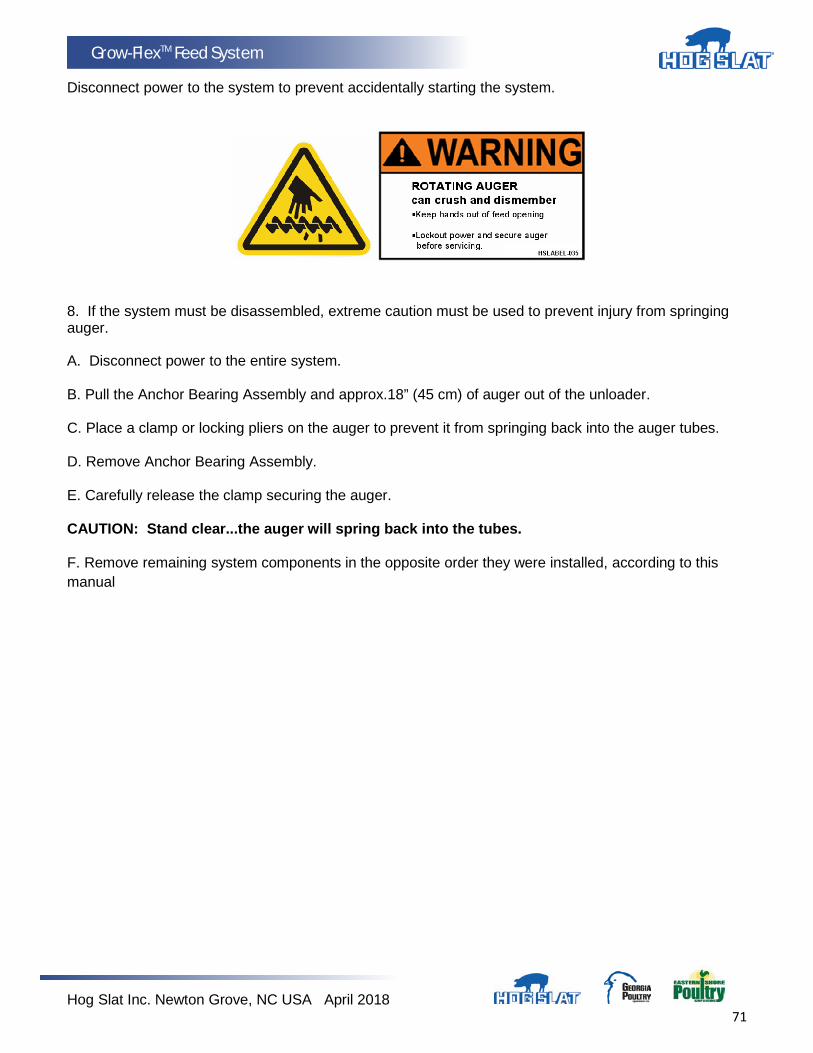
Hog Slat Inc. Newton Grove, NC USA April 2018 71
Grow-FlexTM Feed System
Disconnect power to the system to prevent accidentally starting the system.
8. If the system must be disassembled, extreme caution must be used to prevent injury from springing auger.
A. Disconnect power to the entire system. B. Pull the Anchor Bearing Assembly and approx.18” (45 cm) of auger out of the unloader. C. Place a clamp or locking pliers on the auger to prevent it from springing back into the auger tubes. D. Remove Anchor Bearing Assembly. E. Carefully release the clamp securing the auger. CAUTION: Stand clear...the auger will spring back into the tubes. F. Remove remaining system components in the opposite order they were installed, according to this manual
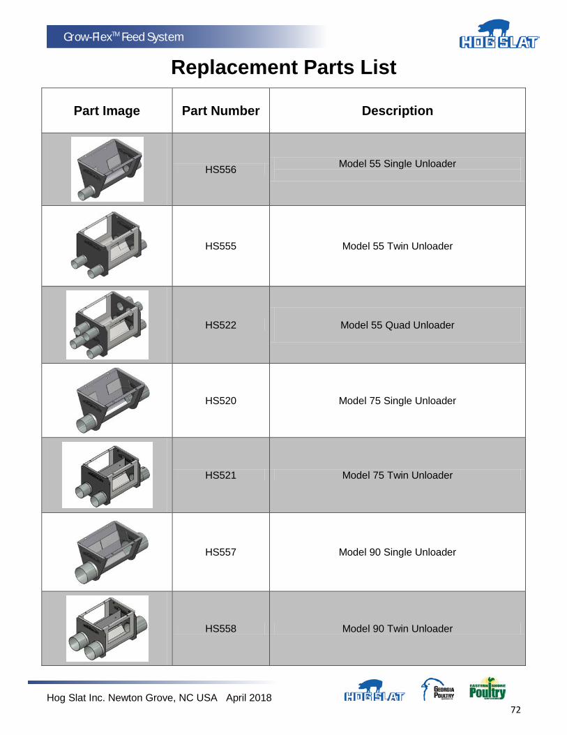
Hog Slat Inc. Newton Grove, NC USA April 2018 72
Grow-FlexTM Feed System
Replacement Parts List
Part Image Part Number
Description
HS556 Model 55 Single Unloader
HS555 Model 55 Twin Unloader
HS522
Model 55 Quad Unloader
HS520 Model 75 Single Unloader
HS521 Model 75 Twin Unloader
HS557 Model 90 Single Unloader
HS558 Model 90 Twin Unloader
Hog Slat Inc. Newton Grove, NC USA April 2018 73
Grow-FlexTM Feed System
HS524 30 Degree Boot
HS525 Straight Out Boot
HSAB55C Model 55 Anchor Bearing
HSAB75C Model 75 Anchor Bearing
HSAB75EC-10 Anchor Bearing M75 Extended
HSAB75E-8 Tube 14' Galvanized For Extended Anchor Bearing
HSAB90U Model 90 Anchor Bearing
HSAB90U-HR Model HR Anchor Bearing
Hog Slat Inc. Newton Grove, NC USA April 2018 74
Grow-FlexTM Feed System
HSDTC01 Drop Tube Control
HS76000 Universal Adjustable Drop Tube
HSDT001 Tube Drop 3.937” ID X 4.125 OD X 12’ GrowerSelect
HSDT002 Tube Drop 3.000” ID X 3.188” OD X 12’ GrowerSelect
HSDT003 Tube Drop 3.562” ID X 3.750” OD X 12” GrowerSelect
HSDT004 Tube Drop 3.937” ID X 4.125” OD X 6’ GrowerSelect
HSDT005 Tube Drop 3.313” ID X 3.500” OD X 6’ GrowerSelect
HSDT006 Tube Drop 4.187 ID X 4.375” OD X 12’ GrowerSelect
Hog Slat Inc. Newton Grove, NC USA April 2018 75
Grow-FlexTM Feed System
HSAT55-S Tube Feed Straight PVC Model 55 10’ GrowerSelect
HSAT75-S Tube Feed Straight PVC Model 75 10’ GrowerSelect
HSAT90-S Tube Feed Straight PVC Model 90 10’ GrowerSelect
HSAT55-C Coupler Feed Tube PVC Model 55 GrowerSelect
HSAT75-C Coupler Feed Tube PVC Model 75 GrowerSelect
HSAT90-C Coupler Feed Tube PVC Model 90 GrowerSelect
HSAT55-45 Elbow 45 Deg PVC Auger 55 5’ Radius GrowerSelect
HSAT55-45-10 Elbow 45 Deg PVC Auger 55 10' Radius
GrowerSelect
HSAT75-45 Elbow 45 Deg PVC Auger 75 5’ Radius GrowerSelect
Hog Slat Inc. Newton Grove, NC USA April 2018 76
Grow-FlexTM Feed System
HSAT90-45 Elbow 45 Deg PVC Auger 90 5’ Radius GrowerSelect
HS655 Drop Adapter M55 GrowerSelect
HS675 Drop Adapter M75 GrowerSelect
HS690 Drop Adapter M90 GrowerSelect
HSSD55 Feeder Sow Drop Dispenser M55 GrowerSelect
HSSD75 Feeder Sow Drop Dispenser M75 GrowerSelect
HSSD90 Feeder Sow Drop Dispenser M90 GrowerSelect
HSSD-CU
Feeder Sow Drop Dispenser with Control Unit for M55, M75, & M90
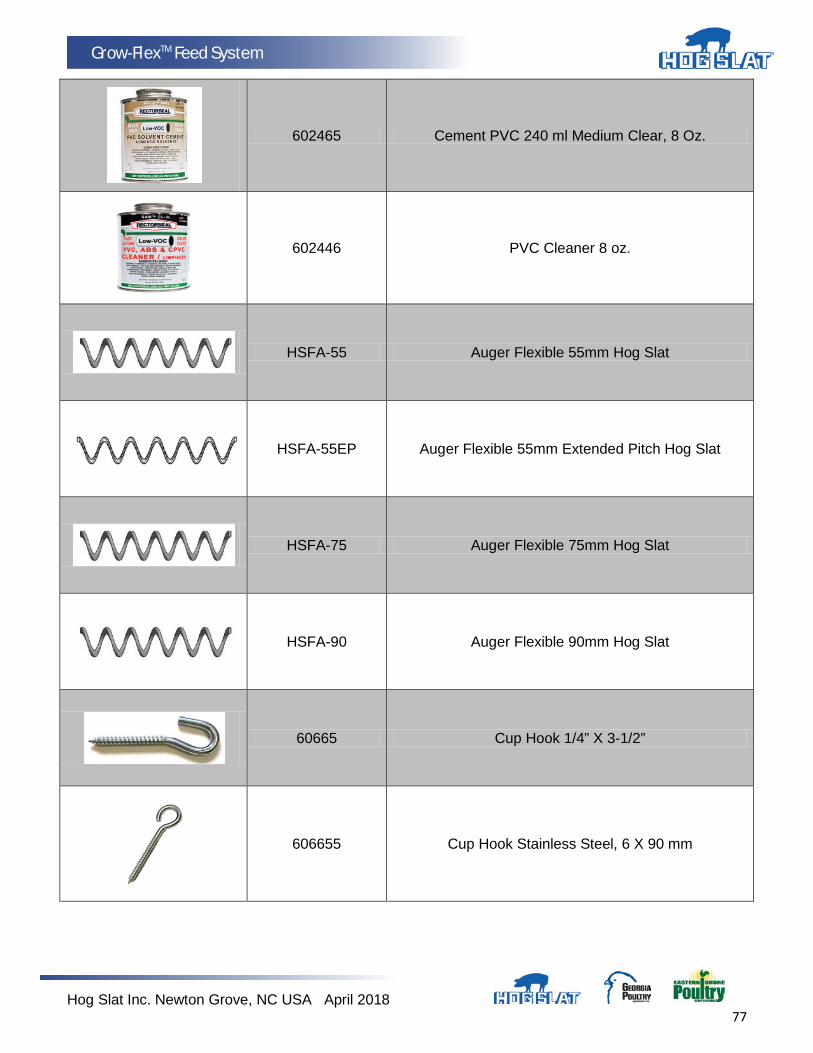
Hog Slat Inc. Newton Grove, NC USA April 2018 77
Grow-FlexTM Feed System
602465 Cement PVC 240 ml Medium Clear, 8 Oz.
602446 PVC Cleaner 8 oz.
HSFA-55 Auger Flexible 55mm Hog Slat
HSFA-55EP Auger Flexible 55mm Extended Pitch Hog Slat
HSFA-75 Auger Flexible 75mm Hog Slat
HSFA-90 Auger Flexible 90mm Hog Slat
60665 Cup Hook 1/4” X 3-1/2”
606655 Cup Hook Stainless Steel, 6 X 90 mm
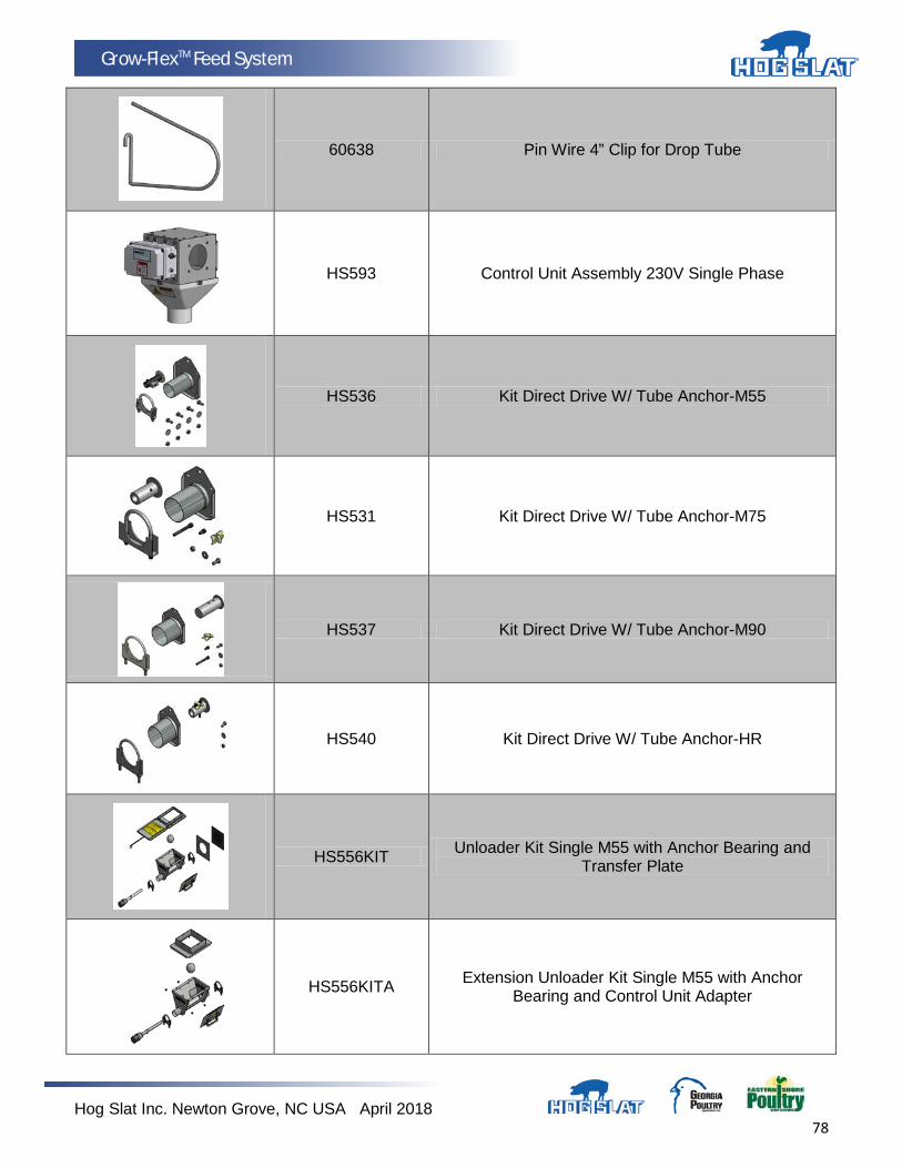
Hog Slat Inc. Newton Grove, NC USA April 2018 78
Grow-FlexTM Feed System
60638 Pin Wire 4” Clip for Drop Tube
HS593 Control Unit Assembly 230V Single Phase
HS536 Kit Direct Drive W/ Tube Anchor-M55
HS531 Kit Direct Drive W/ Tube Anchor-M75
HS537 Kit Direct Drive W/ Tube Anchor-M90
HS540 Kit Direct Drive W/ Tube Anchor-HR
HS556KIT Unloader Kit Single M55 with Anchor Bearing and Transfer Plate
HS556KITA Extension Unloader Kit Single M55 with Anchor Bearing and Control Unit Adapter
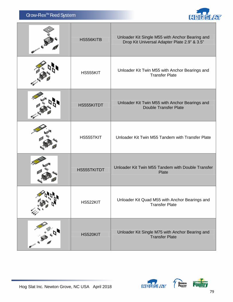
Hog Slat Inc. Newton Grove, NC USA April 2018 79
Grow-FlexTM Feed System
HS556KITB Unloader Kit Single M55 with Anchor Bearing and Drop Kit Universal Adapter Plate 2.9” & 3.5”
HS555KIT Unloader Kit Twin M55 with Anchor Bearings and Transfer Plate
HS555KITDT Unloader Kit Twin M55 with Anchor Bearings and Double Transfer Plate
HS555TKIT Unloader Kit Twin M55 Tandem with Transfer Plate
HS555TKITDT Unloader Kit Twin M55 Tandem with Double Transfer Plate
HS522KIT Unloader Kit Quad M55 with Anchor Bearings and Transfer Plate
HS520KIT Unloader Kit Single M75 with Anchor Bearing and Transfer Plate
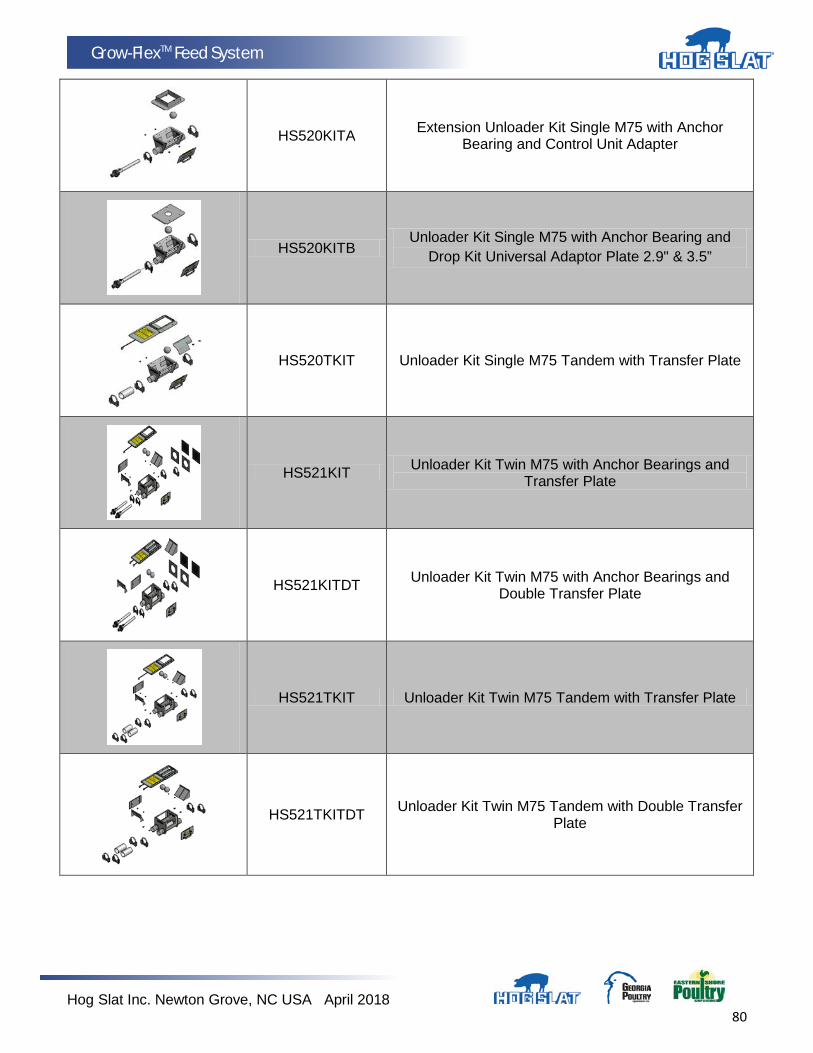
Hog Slat Inc. Newton Grove, NC USA April 2018 80
Grow-FlexTM Feed System
HS520KITA Extension Unloader Kit Single M75 with Anchor Bearing and Control Unit Adapter
HS520KITB Unloader Kit Single M75 with Anchor Bearing and
Drop Kit Universal Adaptor Plate 2.9" & 3.5”
HS520TKIT Unloader Kit Single M75 Tandem with Transfer Plate
HS521KIT Unloader Kit Twin M75 with Anchor Bearings and Transfer Plate
HS521KITDT Unloader Kit Twin M75 with Anchor Bearings and Double Transfer Plate
HS521TKIT Unloader Kit Twin M75 Tandem with Transfer Plate
HS521TKITDT Unloader Kit Twin M75 Tandem with Double Transfer Plate

Hog Slat Inc. Newton Grove, NC USA April 2018 81
Grow-FlexTM Feed System
HS557KIT Unloader Kit Single M90 with Anchor Bearing and Transfer Plate
HS557KITA Extension Unloader Kit Single M90 with Anchor Bearing and Control Unit Adapter
HS557TKIT Unloader Kit Single M90 Tandem with Transfer Plate
HS558KIT Unloader Kit Twin M90 with Anchor Bearings and Transfer Plate
HS557HRKIT Unloader Kit Single Model HR with Anchor Bearing and Transfer Plate
HS557HRTKIT Unloader Kit Single Model HR Tandem with Transfer Plate
HS558HRKIT Unloader Kit Twin Model HR with Anchor Bearings and Transfer Plate
Hog Slat Inc. Newton Grove, NC USA April 2018 82
Grow-FlexTM Feed System
HS558HRTKIT Unloader Kit Twin Model HR Tandem with Transfer Plate
HS558HRTKITDT
Unloader Kit Twin Model HR Tandem with Double
Transfer Plate
HS545 Unloader Kit Twin Bi-Directional Model 75 with Anchor Bearings and Transfer Plate
HS611 Model 75 Control Unit w/o Electrical Box
HS559 Control Unit Adapter Plate
HS559-6 Drop Kit Universal Adapter Plate 2.9” & 3.5” Opening
60677 Medium S Hook
60673 Weldless Chain Galvanized #2
Hog Slat Inc. Newton Grove, NC USA April 2018 83
Grow-FlexTM Feed System
60678
Weldless Chain Galvanized 2/0
606733 Weldless Chain Stainless Steel #1
61732 Cable Clamp 3 mm, 1/8 inch
61739-500 Stainless steel cable, 3 mm, 1/8 inch price 500 foot roll
HS917-416 15 lb Counter Weight
HSAP-2877 Spring .875 OD Baffle
8140150700 Manual Release Lever for Feed Dispensers 1 per 100 drops Inline Only
617471 Split Drum Winch

Hog Slat Inc. Newton Grove, NC USA April 2018 84
Grow-FlexTM Feed System
HS17111 Piano wire 3 mm, 1/8", roll of 122 meters, 400 feet
8120070100 Drill-Adaptable Handle For Winch
8120060100 Manual Handle for Winch
HSH001 Pulley 3 1/2" Cast Iron Complete with Needle Bearings
HS10 Proxy Plus Proximity Switch
HS09 Sensor Feed 230V with Heat & Screw Driver Black Pack
HS9020D1 Drive Unit 1/3 HP With 352 RPM Gearhead For Model 55
HS9020D1-P Drive Unit 1/3HP 352RPM 5/8" Shaft Poultry Feed Line
Hog Slat Inc. Newton Grove, NC USA April 2018 85
Grow-FlexTM Feed System
HS9021D1 Drive Unit 1/2 HP With 352 RPM Gearhead for M55
HS9021D1-P Drive Unit 1/2HP 352RPM 5/8" Shaft Poultry Feed Line
HS9022D2 Drive Unit 3/4 HP With 352 RPM Gearhead for M75 and M90
HS9022D8 Drive Unit 3/4HP w/ 256 RPM Gearhead for M75 & M90
HS9023D2 Drive Unit 1 HP With 352 RPM Gearhead for M75 & M90
HS9023D8 Drive Unit 1HP W/ 256RPM Gearhead For M75 & M90
HS9024D2 Drive Unit 1.5 HP With 352 RPM Gearhead M75 and M90

Hog Slat Inc. Newton Grove, NC USA April 2018 86
Grow-FlexTM Feed System
HS9321D6-50 Gear motor 0.37 kW (0,5 HP) rpm 368, 3 phase 50 Hz, 240/400V
HS9322D6-50 Gear motor 0.55 kW (0,75 HP) rpm 368, 3 phase 50 Hz, 240/400V
HS9324D6-50 Drive Unit 1-1/2 HP W/364 RPM Gearhead 3-PH 50 HZ (190-380V)
HS9321D7-50 Gear motor 0.37 kW (.5 HP) rpm 364, 3 phase 50 Hz, 240/400V
HS9323D8-50 Gear motor 0.75 kW (1 HP) rpm 213, 3 phase 50 Hz, 240/400V
HS9323D6-50 Gear motor 0.75 kW (1 HP) rpm 368, 3 phase 50 Hz, 240/400V
HS9321D6-50 Gear motor 0.37 kW (0,5 HP) rpm 368, 3 phase 50 Hz, 240/400V
Hog Slat Inc. Newton Grove, NC USA April 2018 87
Grow-FlexTM Feed System
Notes
Hog Slat Inc. Newton Grove, NC USA April 2018 88
Grow-FlexTM Feed System
This equipment must be installed in accordance with all State and Local Codes and applicable Regulations which should
be followed in all cases. Authorities having jurisdiction should be consulted before installations are made.
Hog Slat, Inc. PO Box 300
Newton Grove, NC 28366
Phone: (910) 594-0219 Fax: (910) 594-1392
www.hogslat.com
Copyright © 2013 by Hog Slat, Inc.
Part Number: HSManual-020 Rev A6 HSART-197 Market – Hog & Poultry Product Group - GrowerSelect
Rev A6 - Updated several diagrams and added Gearhead parts to charts