model 5 operating and maintenance manual - low water volume
TRANSCRIPT
$25.00 U.S.
Manual Part No. 750-215
11/04
CLEAVER-BROOKSModel 5 Boiler
Size 8000 Low Water Volume
Table Of Contents
SAFETY PRECAUTIONS AND ABBREVIATIONS
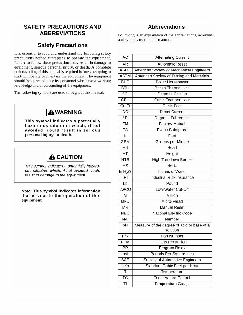
Safety PrecautionsIt is essential to read and understand the following safetyprecautions before attempting to operate the equipment.Failure to follow these precautions may result in damage toequipment, serious personal injury, or death. A completeunderstanding of this manual is required before attempting tostart-up, operate or maintain the equipment. The equipmentshould be operated only by personnel who have a workingknowledge and understanding of the equipment.
The following symbols are used throughout this manual:
! DANGERWARNINGThis symbol indicates a potentiallyhazardous situation which, i f notavoided, could resul t in ser iouspersonal injury, or death.
! DANGERCAUTIONThis symbol indicates a potentially hazard-ous situation which, if not avoided, couldresult in damage to the equipment.
Note: This symbol indicates informationthat is vital to the operation of thisequipment.
AbbreviationsFollowing is an explanation of the abbreviations, acronyms,and symbols used in this manual.
AC Alternating Current
AR Automatic ResetASME American Society of Mechanical EngineersASTM American Society of Testing and MaterialsBHP Boiler HorsepowerBTU British Thermal Unit°C Degrees Celsius
CFH Cubic Feet per HourCu Ft Cubic FeetDC Direct Current°F Degrees FahrenheitFM Factory MutualFS Flame Safeguardft Feet
GPM Gallons per MinuteHd HeadHT Height
HTB High Turndown BurnerHZ Hertz
In H2O Inches of WaterIRI Industrial Risk InsuranceLb Pound
LWCO Low-Water Cut-OffM Million
MFD Micro-Farad MR Manual Reset
NEC National Electric CodeNo. NumberpH Measure of the degree of acid or base of a
solutionP/N Part NumberPPM Parts Per MillionPR Program Relaypsi Pounds Per Square Inch
SAE Society of Automotive Engineersscfh Standard Cubic Feet per Hour
T TemperatureTC Temperature ControlTI Temperature Gauge
Please direct purchase orders for replacement manuals to your local Cleaver-Brooks authorized representative
Manual Part No. 750-215
Revised 11/2004 Printed in U.S.A.
Cleaver-Brooks 2004
CLEAVER-BROOKSModel 5 Boiler
Size 8000 Low Water Volume
i
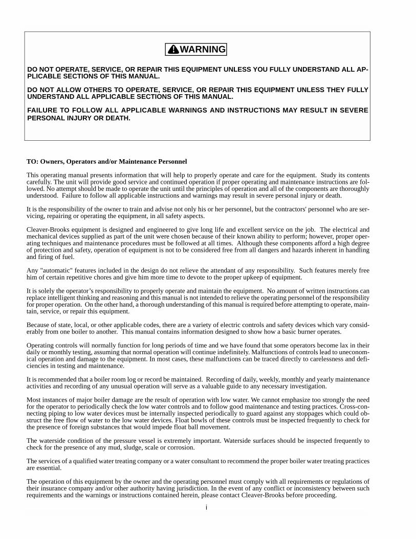
TO: Owners, Operators and/or Maintenance Personnel
This operating manual presents information that will help to properly operate and care for the equipment. Study its contentscarefully. The unit will provide good service and continued operation if proper operating and maintenance instructions are fol-lowed. No attempt should be made to operate the unit until the principles of operation and all of the components are thoroughlyunderstood. Failure to follow all applicable instructions and warnings may result in severe personal injury or death.
It is the responsibility of the owner to train and advise not only his or her personnel, but the contractors' personnel who are ser-vicing, repairing or operating the equipment, in all safety aspects.
Cleaver-Brooks equipment is designed and engineered to give long life and excellent service on the job. The electrical andmechanical devices supplied as part of the unit were chosen because of their known ability to perform; however, proper oper-ating techniques and maintenance procedures must be followed at all times. Although these components afford a high degreeof protection and safety, operation of equipment is not to be considered free from all dangers and hazards inherent in handlingand firing of fuel.
Any "automatic" features included in the design do not relieve the attendant of any responsibility. Such features merely freehim of certain repetitive chores and give him more time to devote to the proper upkeep of equipment.
It is solely the operator’s responsibility to properly operate and maintain the equipment. No amount of written instructions canreplace intelligent thinking and reasoning and this manual is not intended to relieve the operating personnel of the responsibilityfor proper operation. On the other hand, a thorough understanding of this manual is required before attempting to operate, main-tain, service, or repair this equipment.
Because of state, local, or other applicable codes, there are a variety of electric controls and safety devices which vary consid-erably from one boiler to another. This manual contains information designed to show how a basic burner operates.
Operating controls will normally function for long periods of time and we have found that some operators become lax in theirdaily or monthly testing, assuming that normal operation will continue indefinitely. Malfunctions of controls lead to uneconom-ical operation and damage to the equipment. In most cases, these malfunctions can be traced directly to carelessness and defi-ciencies in testing and maintenance.
It is recommended that a boiler room log or record be maintained. Recording of daily, weekly, monthly and yearly maintenanceactivities and recording of any unusual operation will serve as a valuable guide to any necessary investigation.
Most instances of major boiler damage are the result of operation with low water. We cannot emphasize too strongly the needfor the operator to periodically check the low water controls and to follow good maintenance and testing practices. Cross-con-necting piping to low water devices must be internally inspected periodically to guard against any stoppages which could ob-struct the free flow of water to the low water devices. Float bowls of these controls must be inspected frequently to check forthe presence of foreign substances that would impede float ball movement.
The waterside condition of the pressure vessel is extremely important. Waterside surfaces should be inspected frequently tocheck for the presence of any mud, sludge, scale or corrosion.
The services of a qualified water treating company or a water consultant to recommend the proper boiler water treating practicesare essential.
The operation of this equipment by the owner and the operating personnel must comply with all requirements or regulations oftheir insurance company and/or other authority having jurisdiction. In the event of any conflict or inconsistency between suchrequirements and the warnings or instructions contained herein, please contact Cleaver-Brooks before proceeding.
DO NOT OPERATE, SERVICE, OR REPAIR THIS EQUIPMENT UNLESS YOU FULLY UNDERSTAND ALL AP-PLICABLE SECTIONS OF THIS MANUAL.
DO NOT ALLOW OTHERS TO OPERATE, SERVICE, OR REPAIR THIS EQUIPMENT UNLESS THEY FULLYUNDERSTAND ALL APPLICABLE SECTIONS OF THIS MANUAL.
FAILURE TO FOLLOW ALL APPLICABLE WARNINGS AND INSTRUCTIONS MAY RESULT IN SEVEREPERSONAL INJURY OR DEATH.
! DANGERWARNING
Section 1General Description and Principles of Operation
A. The Boiler . . . . . . . . . . . . . . . . . . . . . . . . . . . . . . . . . . . . . . . . . . 1-2B. The Burner . . . . . . . . . . . . . . . . . . . . . . . . . . . . . . . . . . . . . . . . . 1-3C. Steam Controls . . . . . . . . . . . . . . . . . . . . . . . . . . . . . . . . . . . . . . 1-4D. Level Control, Water Column & Safety Valve. . . . . . . . . . . . . . . . . . 1-4E. Burner Controls. . . . . . . . . . . . . . . . . . . . . . . . . . . . . . . . . . . . . . 1-5
Section 2Profire Burner
A. Firing Tube . . . . . . . . . . . . . . . . . . . . . . . . . . . . . . . . . . . . . . . . . 2-2B. Blower Housing/Motor/Damper . . . . . . . . . . . . . . . . . . . . . . . . . . . 2-2C. Gas Components . . . . . . . . . . . . . . . . . . . . . . . . . . . . . . . . . . . . . 2-3D. Oil Components . . . . . . . . . . . . . . . . . . . . . . . . . . . . . . . . . . . . . . 2-5E. Ignition Components . . . . . . . . . . . . . . . . . . . . . . . . . . . . . . . . . . 2-5F. Safety and Controls . . . . . . . . . . . . . . . . . . . . . . . . . . . . . . . . . . . . 2-6G. Automatic Ignition . . . . . . . . . . . . . . . . . . . . . . . . . . . . . . . . . . . . 2-6H. Combustion Air . . . . . . . . . . . . . . . . . . . . . . . . . . . . . . . . . . . . . . 2-7I. Operation - Natural Gas . . . . . . . . . . . . . . . . . . . . . . . . . . . . . . . . . 2-7
Section 3The Pressure Vessel
A. General . . . . . . . . . . . . . . . . . . . . . . . . . . . . . . . . . . . . . . . . . . . . 3-2B. Construction . . . . . . . . . . . . . . . . . . . . . . . . . . . . . . . . . . . . . . . . 3-2C. Water Requirements . . . . . . . . . . . . . . . . . . . . . . . . . . . . . . . . . . . 3-3
Hot Water Boiler . . . . . . . . . . . . . . . . . . . . . . . . . . . . . . . . . . . 3-3Air Removal . . . . . . . . . . . . . . . . . . . . . . . . . . . . . . . . . . . . . . 3-3Continuous Flow . . . . . . . . . . . . . . . . . . . . . . . . . . . . . . . . . . . 3-3Multiple Boiler Installation . . . . . . . . . . . . . . . . . . . . . . . . . . . . 3-3Pressure Drop . . . . . . . . . . . . . . . . . . . . . . . . . . . . . . . . . . . . 3-3Pressure . . . . . . . . . . . . . . . . . . . . . . . . . . . . . . . . . . . . . . . . 3-4Steam Boiler . . . . . . . . . . . . . . . . . . . . . . . . . . . . . . . . . . . . . 3-4Feed Pump Operation . . . . . . . . . . . . . . . . . . . . . . . . . . . . . . . 3-4Minimum Boiler Water Temperature . . . . . . . . . . . . . . . . . . . . . 3-4
D. Water Treatment . . . . . . . . . . . . . . . . . . . . . . . . . . . . . . . . . . . . 3-4Objectives of water treatment in general are: . . . . . . . . . . . . . . . 3-5
E. Cleaning . . . . . . . . . . . . . . . . . . . . . . . . . . . . . . . . . . . . . . . . . . 3-5F. Boil-Out of a New Unit . . . . . . . . . . . . . . . . . . . . . . . . . . . . . . . . . 3-7G. Washing Out . . . . . . . . . . . . . . . . . . . . . . . . . . . . . . . . . . . . . . . 3-9
Steam Boiler . . . . . . . . . . . . . . . . . . . . . . . . . . . . . . . . . . . . . 3-9Hot Water Boiler . . . . . . . . . . . . . . . . . . . . . . . . . . . . . . . . . . . 3-9Flushing of Pressure Vessel Interior . . . . . . . . . . . . . . . . . . . . . . 3-9
H. Blowdown — Steam Boiler . . . . . . . . . . . . . . . . . . . . . . . . . . . . . 3-9Types of Blowdown . . . . . . . . . . . . . . . . . . . . . . . . . . . . . . . . 3-10Intermittent Blowdown . . . . . . . . . . . . . . . . . . . . . . . . . . . . . 3-10Continuous Blowdown . . . . . . . . . . . . . . . . . . . . . . . . . . . . . . 3-11Frequency of Intermittent Blowdown . . . . . . . . . . . . . . . . . . . . 3-11Manual Blowdown Procedure . . . . . . . . . . . . . . . . . . . . . . . . . 3-12
I. Periodic Inspection . . . . . . . . . . . . . . . . . . . . . . . . . . . . . . . . . . . 3-12J. Fireside Cleaning . . . . . . . . . . . . . . . . . . . . . . . . . . . . . . . . . . . . 3-14K. Water Washing — Fireside (Oil Fired Unit) . . . . . . . . . . . . . . . . . . 3-15
L. Preparation for Extended Lay-Up . . . . . . . . . . . . . . . . . . . . . . . . 3-16Dry Storage . . . . . . . . . . . . . . . . . . . . . . . . . . . . . . . . . . . . . 3-16Wet Storage . . . . . . . . . . . . . . . . . . . . . . . . . . . . . . . . . . . . . 3-16
Section 4Sequence Of Operation
A. General . . . . . . . . . . . . . . . . . . . . . . . . . . . . . . . . . . . . . . . . . . . 4-2B. Circuit and Interlock Controls . . . . . . . . . . . . . . . . . . . . . . . . . . . . 4-2C. Sequence of Operation - Oil or Gas . . . . . . . . . . . . . . . . . . . . . . . . 4-5D. Flame Loss Sequence . . . . . . . . . . . . . . . . . . . . . . . . . . . . . . . . . 4-7
Section 5Starting and Operating Instructions
A. General Preparation for Initial Startup . . . . . . . . . . . . . . . . . . . . . . 5-2B. Startup Procedures . . . . . . . . . . . . . . . . . . . . . . . . . . . . . . . . . . . 5-6C. Burner Adjustments, Single Fuel Natural Gas . . . . . . . . . . . . . . . . . 5-8D. Burner Adjustments, Single Fuel, Oil-fired
(Return Flow Pressure Atomization) . . . . . . . . . . . . . . . . . . . . . . . 5-12E. Burner Adjustments, Combination Gas and Oil . . . . . . . . . . . . . . . 5-14F. Startup, Operating And Shutdown - All Fuels . . . . . . . . . . . . . . . . . 5-19
Section 6Adjustment and Maintenance
A. General . . . . . . . . . . . . . . . . . . . . . . . . . . . . . . . . . . . . . . . . . . . 6-2B. Periodic Inspection . . . . . . . . . . . . . . . . . . . . . . . . . . . . . . . . . . . 6-3C. Water Level Controls and Waterside of Pressure Vessel . . . . . . . . . . . 6-3D. Water Gauge Glass . . . . . . . . . . . . . . . . . . . . . . . . . . . . . . . . . . . 6-5E. Operating Controls . . . . . . . . . . . . . . . . . . . . . . . . . . . . . . . . . . . . 6-5
1. Setting and Adjusting . . . . . . . . . . . . . . . . . . . . . . . . . . . . . 6-62. Pressure Controls — Steam Boiler . . . . . . . . . . . . . . . . . . . . 6-73. Temperature Controls — Hot Water Boiler . . . . . . . . . . . . . . . 6-94. Combustion Air Proving Switch . . . . . . . . . . . . . . . . . . . . . 6-105. Low Gas Pressure Switch . . . . . . . . . . . . . . . . . . . . . . . . . 6-116. High Gas Pressure Switch . . . . . . . . . . . . . . . . . . . . . . . . . 6-117. Low Oil Pressure Switch (Optional) . . . . . . . . . . . . . . . . . . . 6-118. Programming Control . . . . . . . . . . . . . . . . . . . . . . . . . . . . 6-119. Control Operational Test . . . . . . . . . . . . . . . . . . . . . . . . . . 6-13
F. Oil Burner . . . . . . . . . . . . . . . . . . . . . . . . . . . . . . . . . . . . . . . . . 6-141. General . . . . . . . . . . . . . . . . . . . . . . . . . . . . . . . . . . . . . . 6-142. Oil Pump . . . . . . . . . . . . . . . . . . . . . . . . . . . . . . . . . . . . . 6-153. Combustion Adjustment — Oil . . . . . . . . . . . . . . . . . . . . . . 6-16
G. Gas Burner . . . . . . . . . . . . . . . . . . . . . . . . . . . . . . . . . . . . . . . . 6-171. General . . . . . . . . . . . . . . . . . . . . . . . . . . . . . . . . . . . . . . 6-172. Gas Pilot Flame Adjustment . . . . . . . . . . . . . . . . . . . . . . . 6-173. Gas Pressure and Flow Information . . . . . . . . . . . . . . . . . . 6-194. Combustion Adjustment — Gas . . . . . . . . . . . . . . . . . . . . . 6-22
H. Damper Motor and Auxiliary Switches . . . . . . . . . . . . . . . . . . . . . 6-24I. Air Damper Adjustment . . . . . . . . . . . . . . . . . . . . . . . . . . . . . . . . 6-26J. Safety Valves . . . . . . . . . . . . . . . . . . . . . . . . . . . . . . . . . . . . . . . 6-28K. Motorized Gas Valve . . . . . . . . . . . . . . . . . . . . . . . . . . . . . . . . . . 6-29
L. Solenoid Valves: Gas Pilot/Fuel Oil/Vent Valves . . . . . . . . . . . . . . . 6-30M. Refractory . . . . . . . . . . . . . . . . . . . . . . . . . . . . . . . . . . . . . . . . 6-30N. Fuel Changeover Maintenance . . . . . . . . . . . . . . . . . . . . . . . . . . 6-31O. Forced Draft Fan . . . . . . . . . . . . . . . . . . . . . . . . . . . . . . . . . . . . 6-31P. Furnace Access and Fireside Cleaning . . . . . . . . . . . . . . . . . . . . . . 6-31
Section 7Troubleshooting
A.Burner Does Not Start . . . . . . . . . . . . . . . . . . . . . . . . . . . . . . . . 7-2B.No Ignition . . . . . . . . . . . . . . . . . . . . . . . . . . . . . . . . . . . . . . . . 7-3C.Pilot Flame, But No Main Flame . . . . . . . . . . . . . . . . . . . . . . . . . 7-4D.Burner Stays in Low Fire . . . . . . . . . . . . . . . . . . . . . . . . . . . . . . 7-4E.Shutdown Occurs During Firing . . . . . . . . . . . . . . . . . . . . . . . . . . 7-5F.Damper Motor Does Not Operate . . . . . . . . . . . . . . . . . . . . . . . . . 7-6
Section 8Parts

Notes
Milwaukee, Wisconsin
www.cleaver-brooks.com
Section 1General Description and Principles of Operation
A. The Boiler . . . . . . . . . . . . . . . . . . . . . . . . . . . . . . . . . . . . . . . . . . 1-2B. The Burner . . . . . . . . . . . . . . . . . . . . . . . . . . . . . . . . . . . . . . . . . 1-3C. Steam Controls . . . . . . . . . . . . . . . . . . . . . . . . . . . . . . . . . . . . . . 1-4D. Level Control, Water Column & Safety Valve . . . . . . . . . . . . . . . . . . 1-4E. Burner Controls . . . . . . . . . . . . . . . . . . . . . . . . . . . . . . . . . . . . . . 1-5
Section 1 — General Description and Principles of Operation
1-2 Part No. 750-215
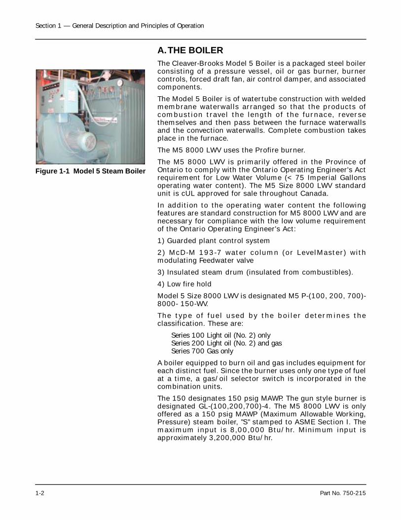
A.THE BOILERThe Cleaver-Brooks Model 5 Boiler is a packaged steel boilerconsisting of a pressure vessel, oil or gas burner, burnercontrols, forced draft fan, air control damper, and associatedcomponents.
The Model 5 Boiler is of watertube construction with weldedmembrane waterwalls arranged so that the products ofcombustion travel the length of the furnace, reversethemselves and then pass between the furnace waterwallsand the convection waterwalls. Complete combustion takesplace in the furnace.
The M5 8000 LWV uses the Profire burner.
The M5 8000 LWV is primarily offered in the Province ofOntario to comply with the Ontario Operating Engineer's Actrequirement for Low Water Volume (< 75 Imperial Gallonsoperating water content). The M5 Size 8000 LWV standardunit is cUL approved for sale throughout Canada.
In addition to the operating water content the followingfeatures are standard construction for M5 8000 LWV and arenecessary for compliance with the low volume requirementof the Ontario Operating Engineer's Act:
1) Guarded plant control system
2) McD-M 193-7 water column (or LevelMaster) withmodulating Feedwater valve
3) Insulated steam drum (insulated from combustibles).
4) Low fire hold
Model 5 Size 8000 LWV is designated M5 P-(100, 200, 700)-8000- 150-WV.
The type of fuel used by the boiler determines theclassification. These are:
Series 100 Light oil (No. 2) onlySeries 200 Light oil (No. 2) and gasSeries 700 Gas only
A boiler equipped to burn oil and gas includes equipment foreach distinct fuel. Since the burner uses only one type of fuelat a time, a gas/oil selector switch is incorporated in thecombination units.
The 150 designates 150 psig MAWP. The gun style burner isdesignated GL-(100,200,700)-4. The M5 8000 LWV is onlyoffered as a 150 psig MAWP (Maximum Allowable Working,Pressure) steam boiler, "S" stamped to ASME Section I. Themaximum input is 8,00,000 Btu/hr. Minimum input isapproximately 3,200,000 Btu/hr.
Figure 1-1 Model 5 Steam Boiler
Section 1 — General Description and Principles of Operation
Part No. 750-215 1-3
Installation should also conform to provincial and localcodes governing such equipment. Prior to installation theproper authorities having jurisdiction are to be consulted,permits obtained, etc. Installation should also conform tostate and local codes governing such equipment. Prior toinstallation, the proper authorities having jurisdiction are tobe consulted, permits obtained etc. All Model 5 boilers in theabove series comply, when equipped with optionalequipment, to Factory Insurance Association (F. I. A.),Factory Mutual (FM) or other insuring underwritersrequirements.
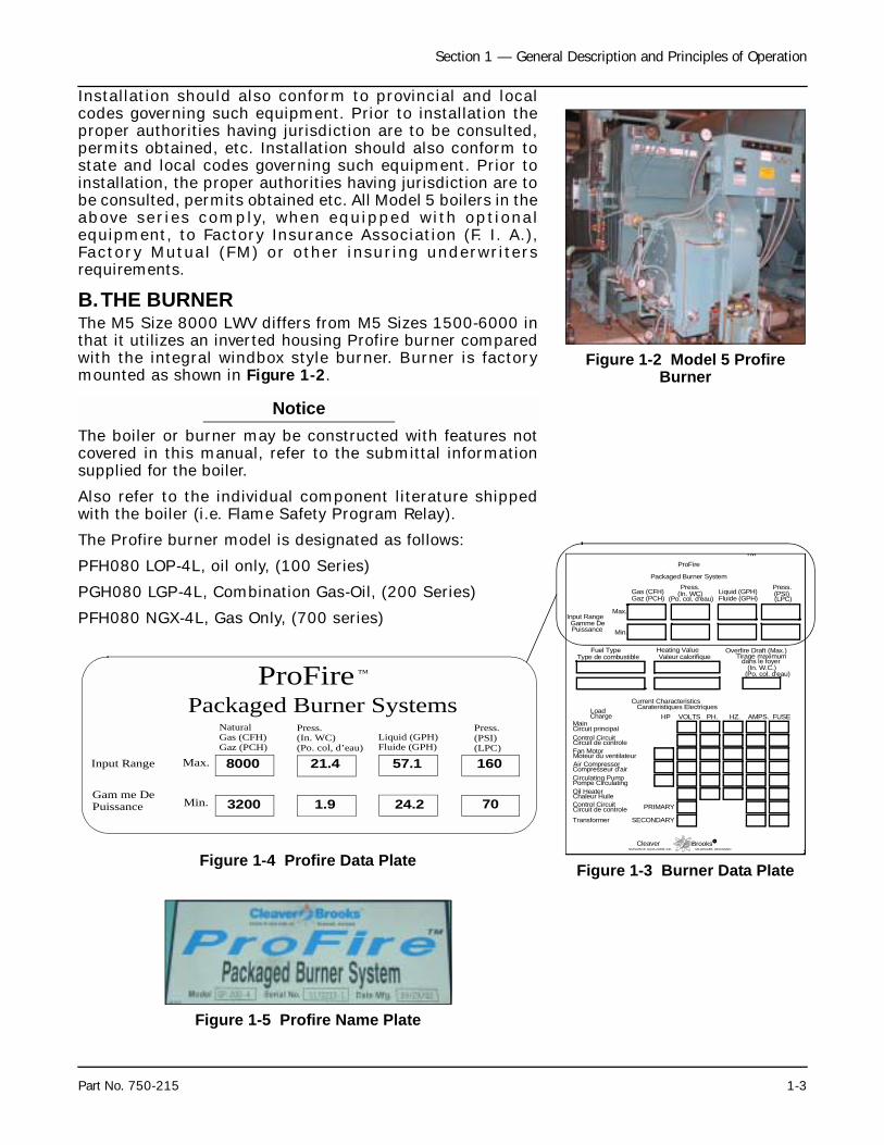
B.THE BURNER The M5 Size 8000 LWV differs from M5 Sizes 1500-6000 inthat it utilizes an inverted housing Profire burner comparedwith the integral windbox style burner. Burner is factorymounted as shown in Figure 1-2.
NoticeThe boiler or burner may be constructed with features notcovered in this manual, refer to the submittal informationsupplied for the boiler.
Also refer to the individual component literature shippedwith the boiler (i.e. Flame Safety Program Relay).
The Profire burner model is designated as follows:
PFH080 LOP-4L, oil only, (100 Series)
PGH080 LGP-4L, Combination Gas-Oil, (200 Series)
PFH080 NGX-4L, Gas Only, (700 series)
Figure 1-4 Profire Data Plate
Figure 1-2 Model 5 Profire Burner
Figure 1-3 Burner Data Plate
Packaged Burner System
Fan Motor
BrooksMILWAUKEE, WISCONSINDIVISION OF AQUA-CHEM, INC.
R
Air CompressorMoteur du ventilateur
Compresseur d'air
Cleaver
PH.Main
LoadHP VOLTS
Control Circuit
HZ. AMPS.
Current CharacteristicsCarateristiques Electriques
Charge
Circuit principal
Circuit de controle
(LPC)(PSI)Press.
Liquid (GPH)Fluide (GPH)
Gas (CFH)Gaz (PCH)
Min.
Max.
(Po. col. d'eau)
Press.(In. WC)
Type de combustibleFuel Type Heating Value
Valeur calorifique
Gamme DeInput Range
TMProFire
FUSE
Control CircuitCircuit de controleTransformer
PRIMARY
SECONDARY
(Po. col. d'eau)(In. W.C.)
Overfire Draft (Max.)dans le foyer
Tirage maximum
Puissance
Pompe CirculatingCirculating Pump
Chaleur HuileOil Heater
Figure 1-5 Profire Name Plate
ProFirePackaged Burner Systems
™
NaturalGas (CFH)Gaz (PCH)
Press.(In. WC)(Po. col, d’eau)
Liquid (GPH)Fluide (GPH)
Press.(PSI)(LPC)
Input Range
Gam me DePuissance
Max.
Min.
8000
3200
21.4
1.9
57.1
24.2
160
70
Section 1 — General Description and Principles of Operation
1-4 Part No. 750-215
C.STEAM CONTROLS1. High Limit Pressure Control (Figure 1-6): Breaks a circuit
to stop burner operation on a rise of pressure above aselected setting. It is adjusted to stop the burner at apreselected pressure above the operating limit controlsetting. The high limit pressure control is equipped with amanual reset.
2. Operating Limit Pressure Control (Figure 1-6): Breaks acircuit to stop burner operation on a rise of boilerpressure at a selected setting. It is adjusted to stop orstart the burner at a preselected pressure setting.
3. Modulating Pressure Control (Figure 1-6): Senseschanging boiler pressures and transmits the informationto the modulating motor to change the burner firing ratewhen the manual-automatic switch is set on “automatic.”
4. Pressure Gauge (Figure 1-6): Monitors the internalpressure of the boiler
D.LEVEL CONTROL, WATER COLUMN & SAFETY VALVE
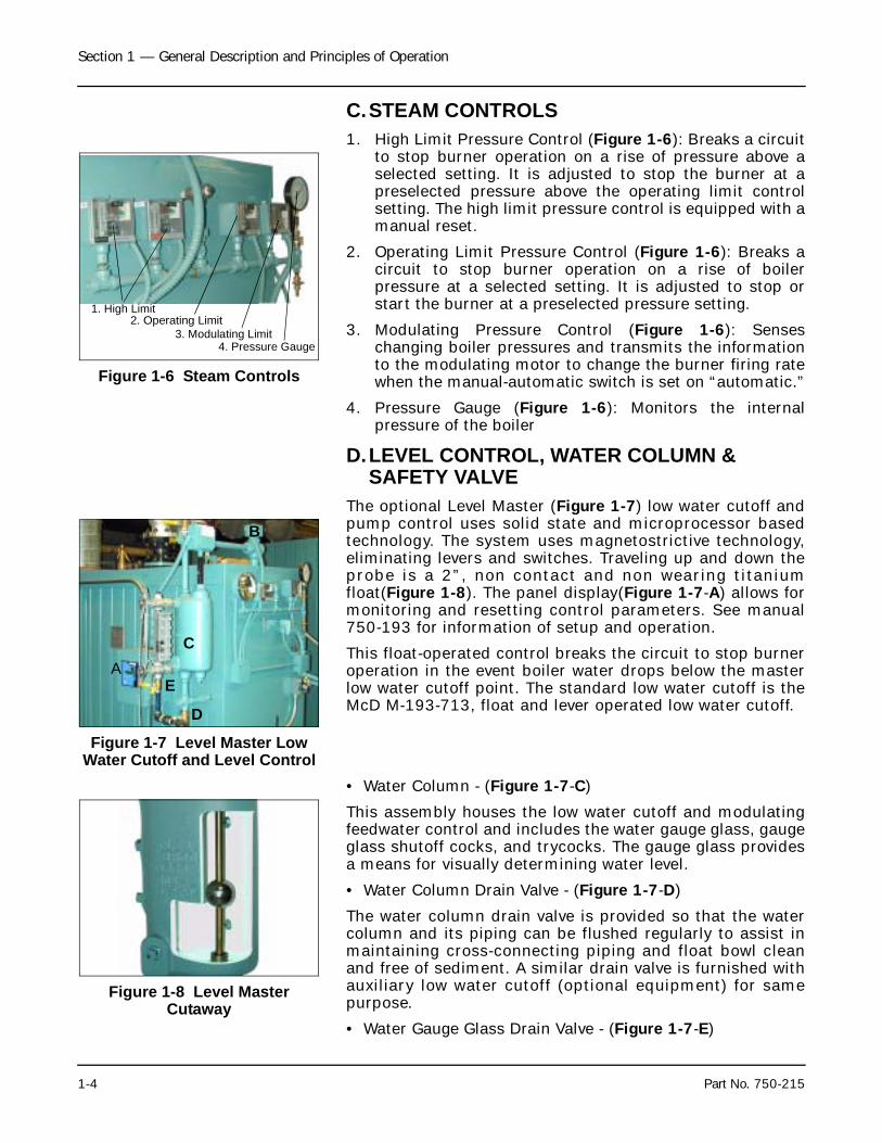
The optional Level Master (Figure 1-7) low water cutoff andpump control uses solid state and microprocessor basedtechnology. The system uses magnetostrictive technology,eliminating levers and switches. Traveling up and down theprobe is a 2”, non contact and non wearing titaniumfloat(Figure 1-8). The panel display(Figure 1-7-A) allows formonitoring and resetting control parameters. See manual750-193 for information of setup and operation.
This float-operated control breaks the circuit to stop burneroperation in the event boiler water drops below the masterlow water cutoff point. The standard low water cutoff is theMcD M-193-713, float and lever operated low water cutoff.
• Water Column - (Figure 1-7-C)
This assembly houses the low water cutoff and modulatingfeedwater control and includes the water gauge glass, gaugeglass shutoff cocks, and trycocks. The gauge glass providesa means for visually determining water level.
• Water Column Drain Valve - (Figure 1-7-D)
The water column drain valve is provided so that the watercolumn and its piping can be flushed regularly to assist inmaintaining cross-connecting piping and float bowl cleanand free of sediment. A similar drain valve is furnished withauxiliary low water cutoff (optional equipment) for samepurpose.
• Water Gauge Glass Drain Valve - (Figure 1-7-E)
Figure 1-6 Steam Controls
1. High Limit2. Operating Limit
3. Modulating Limit4. Pressure Gauge
Figure 1-7 Level Master Low Water Cutoff and Level Control
B
C
D
EA
Figure 1-8 Level Master Cutaway
Section 1 — General Description and Principles of Operation
Part No. 750-215 1-5
This valve is provided to flush the gauge glass.
• Auxiliary Low/High Water Cutoff - (Figure 1-7-B)(Optional equipment)
The manual reset type requires resetting in order to start theburner after a low water condition.
Safety Valve(s) (Figure 1-9): Prevent buildup over the designpressure of the pressure vessel. The size, rating and numberof valves on a boiler is determined by the ASME Boiler Code.The safety valves and the discharge piping are to be installedto conform to the ASME code requirements. The installationof a valve is of primary importance to its service life. A valvemust be mounted in a vertical position so that dischargepiping and code-required drains can be properly piped toprevent buildup of back pressure and accumulation offoreign material around the valve seat area. Apply only amoderate amount of pipe compound to male threads andavoid overtightening, which can distort the seats.
Use only flat-jawed wrenches on the flats provided. Wheninstalling a flange-connected valve, use a new gasket anddraw the mounting bolts down evenly. Do not install orremove side outlet valves by using a pipe or wrench in theoutlet.
E. BURNER CONTROLSThe burner can be equipped with special operating controls,various types of flame safety control systems.
The wiring and dimension diagrams and constructionreference list (available with the burner) confirm the specificfeatures and equipment included. Refer to Figures 1-8 and 1-9 for component locations. The following list describescomponents and basic functions of the burner.
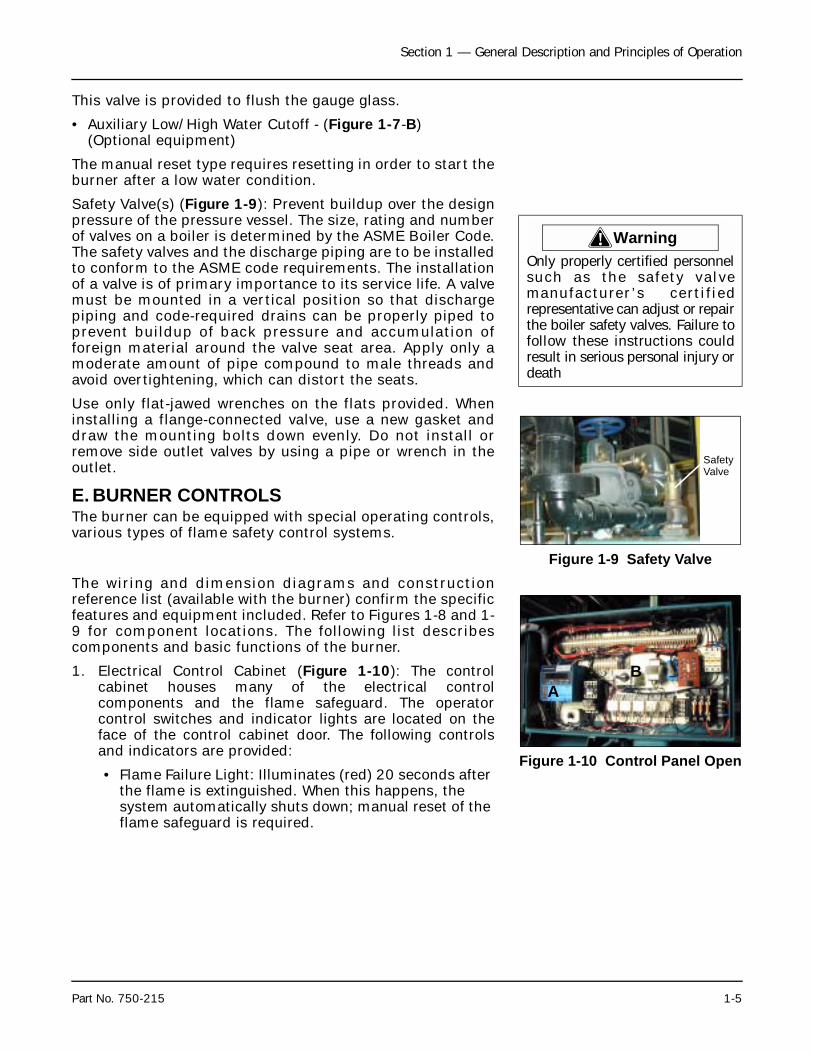
1. Electrical Control Cabinet (Figure 1-10): The controlcabinet houses many of the electrical controlcomponents and the flame safeguard. The operatorcontrol switches and indicator lights are located on theface of the control cabinet door. The following controlsand indicators are provided:
• Flame Failure Light: Illuminates (red) 20 seconds after the flame is extinguished. When this happens, the system automatically shuts down; manual reset of the flame safeguard is required.
! WarningOnly properly certified personnelsuch as the sa fe t y va l vemanu fac tu re r ’ s ce r t i f i edrepresentative can adjust or repairthe boiler safety valves. Failure tofollow these instructions couldresult in serious personal injury ordeath
Figure 1-9 Safety Valve
SafetyValve
Figure 1-10 Control Panel Open
AB
Section 1 — General Description and Principles of Operation
1-6 Part No. 750-215
• Load Demand Light: Illuminates (white) when the boiler operating controls indicate a demand for hot water or steam.
• Burner Switch: Activates or deactivates the operating cycle of the flame safeguard control.
• Manual Flame Control: When in Manual Mode, it provides manual adjustment of the burner firing rate between low-fire and high-fire operation.
• Manual-Auto Switch: Allows the operator to override the automatic boiler controls for manual firing rate adjustment.
• Fuel Valve Light: Illuminates (green) when the selected fuel valve is energized.
• Low Water Light: Illuminates (red) when the boiler low-water cutoff control is activated.
2. Flame Safety Control(Figure 1-10-A): The flame safetycontrols the operating sequences of the combustionsystem (prepurge, pilot, firing, and shutdown). Thecontrol also monitors the flame, using a scanner which issensitive to specific flame frequencies. The flame safetyalso automatically shuts down the burner when the flamesignal becomes too weak. Different types of flame safetydevices can be installed in the combustion systems.Check the wiring diagram for your burner for informationon the specific unit installed on your burner.
3. Fuel Selection Switch (Figure 1-10-B): Allows theoperator to select either gas or oil as the active fuel oncombination burners. (The switch is located inside thecontrol cabinet.)
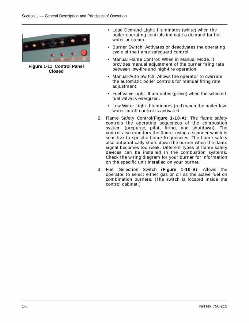
Figure 1-11 Control Panel Closed

Milwaukee, Wisconsin
www.cleaver-brooks.com
Section 2Profire Burner
A. Firing Tube . . . . . . . . . . . . . . . . . . . . . . . . . . . . . . . . . . . . . . . . . 2-2B. Blower Housing/Motor/Damper . . . . . . . . . . . . . . . . . . . . . . . . . . . 2-2C. Gas Components . . . . . . . . . . . . . . . . . . . . . . . . . . . . . . . . . . . . . 2-3D. Oil Components . . . . . . . . . . . . . . . . . . . . . . . . . . . . . . . . . . . . . 2-5E. Ignition Components . . . . . . . . . . . . . . . . . . . . . . . . . . . . . . . . . . 2-5F. Safety and Controls . . . . . . . . . . . . . . . . . . . . . . . . . . . . . . . . . . . 2-6G. Automatic Ignition . . . . . . . . . . . . . . . . . . . . . . . . . . . . . . . . . . . . 2-6H. Combustion Air . . . . . . . . . . . . . . . . . . . . . . . . . . . . . . . . . . . . . . 2-7I. Operation - Natural Gas . . . . . . . . . . . . . . . . . . . . . . . . . . . . . . . . 2-7
Section 2 — Profire Burner
2-2 Part No. 750-215
S
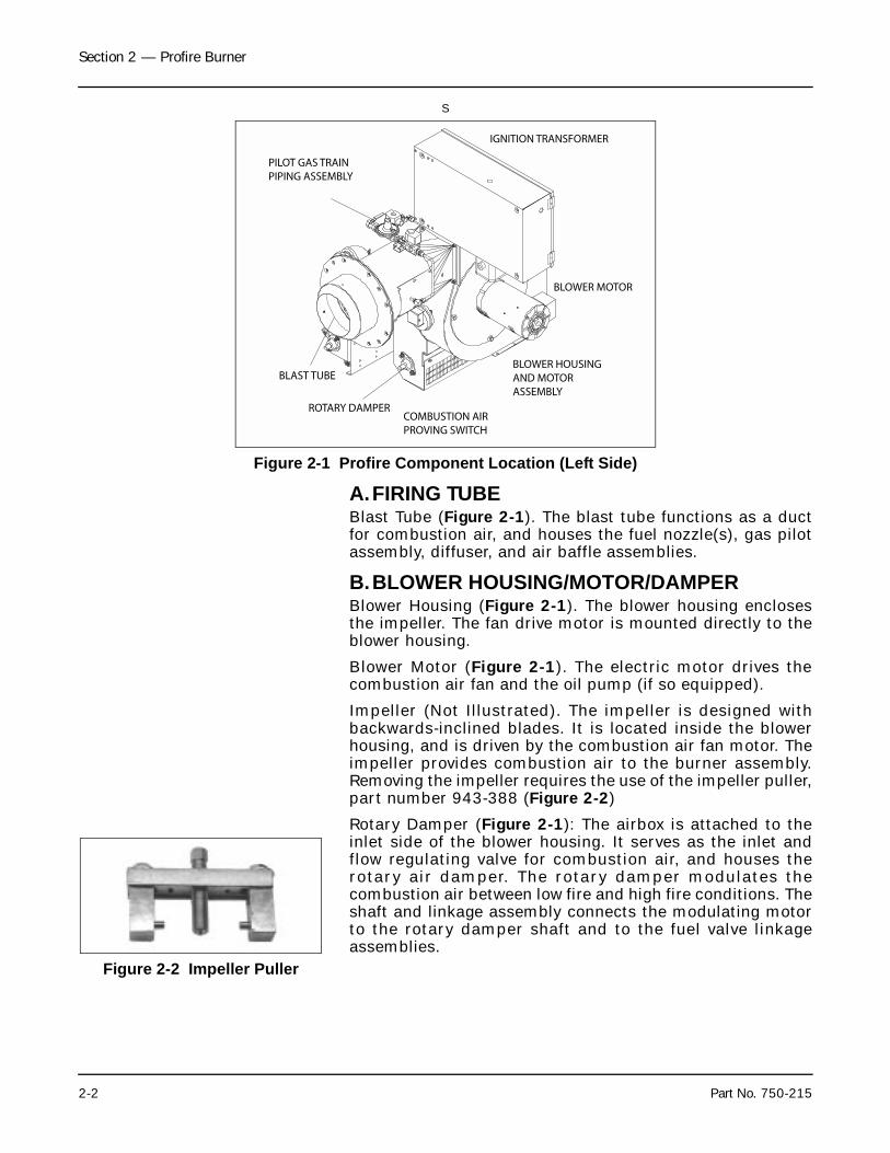
A.FIRING TUBEBlast Tube (Figure 2-1). The blast tube functions as a ductfor combustion air, and houses the fuel nozzle(s), gas pilotassembly, diffuser, and air baffle assemblies.
B.BLOWER HOUSING/MOTOR/DAMPERBlower Housing (Figure 2-1). The blower housing enclosesthe impeller. The fan drive motor is mounted directly to theblower housing.
Blower Motor (Figure 2-1). The electric motor drives thecombustion air fan and the oil pump (if so equipped).
Impeller (Not Illustrated). The impeller is designed withbackwards-inclined blades. It is located inside the blowerhousing, and is driven by the combustion air fan motor. Theimpeller provides combustion air to the burner assembly.Removing the impeller requires the use of the impeller puller,part number 943-388 (Figure 2-2)
Rotary Damper (Figure 2-1): The airbox is attached to theinlet side of the blower housing. It serves as the inlet andflow regulating valve for combustion air, and houses therotary air damper. The rotary damper modulates thecombustion air between low fire and high fire conditions. Theshaft and linkage assembly connects the modulating motorto the rotary damper shaft and to the fuel valve linkageassemblies.
Figure 2-1 Profire Component Location (Left Side)
PILOT GAS TRAINPIPING ASSEMBLY
IGNITION TRANSFORMER
BLOWER MOTOR
BLOWER HOUSINGAND MOTORASSEMBLY
COMBUSTION AIRPROVING SWITCH
ROTARY DAMPER
BLAST TUBE
Figure 2-2 Impeller Puller
Section 2 — Profire Burner
Part No. 750-215 2-3
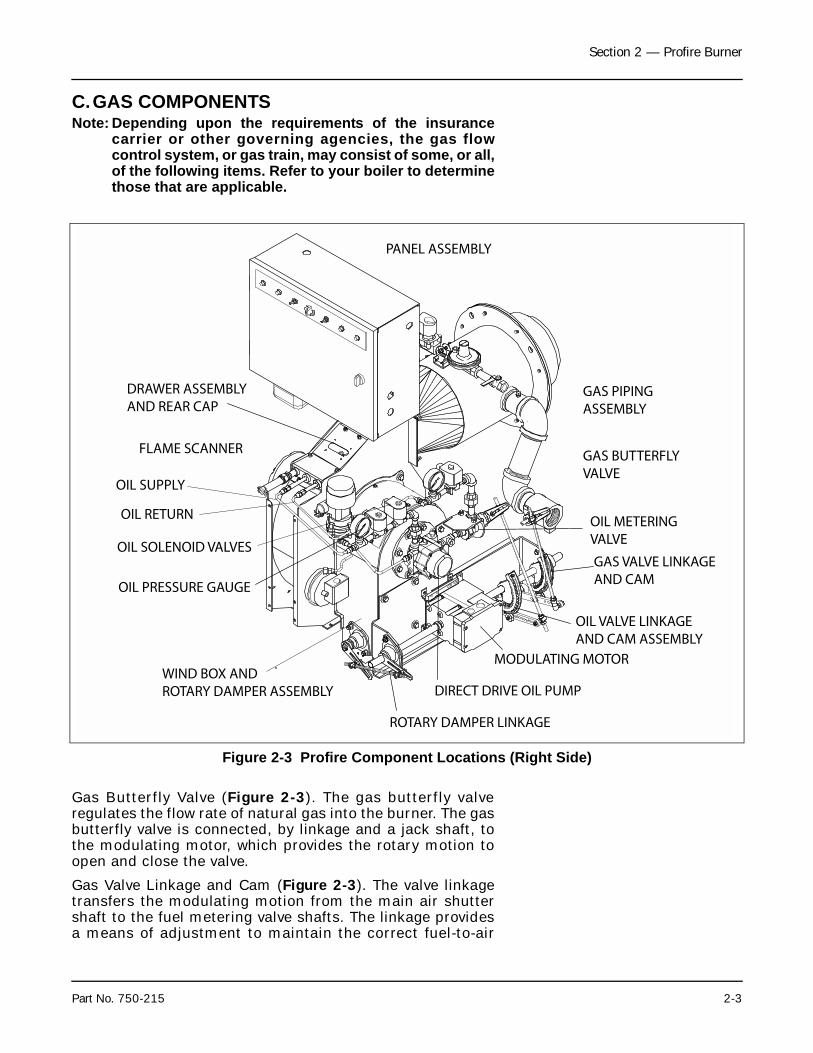
C.GAS COMPONENTSNote: Depending upon the requirements of the insurance
carrier or other governing agencies, the gas flowcontrol system, or gas train, may consist of some, or all,of the following items. Refer to your boiler to determinethose that are applicable.
Gas Butterfly Valve (Figure 2-3). The gas butterfly valveregulates the flow rate of natural gas into the burner. The gasbutterfly valve is connected, by linkage and a jack shaft, tothe modulating motor, which provides the rotary motion toopen and close the valve.
Gas Valve Linkage and Cam (Figure 2-3). The valve linkagetransfers the modulating motion from the main air shuttershaft to the fuel metering valve shafts. The linkage providesa means of adjustment to maintain the correct fuel-to-air
Figure 2-3 Profire Component Locations (Right Side)
ROTARY DAMPER LINKAGE
DIRECT DRIVE OIL PUMP
MODULATING MOTOR
OIL VALVE LINKAGEAND CAM ASSEMBLY
GAS VALVE LINKAGEAND CAM
OIL METERINGVALVE
GAS BUTTERFLYVALVE
GAS PIPINGASSEMBLY
PANEL ASSEMBLY
DRAWER ASSEMBLYAND REAR CAP
FLAME SCANNER
OIL SUPPLY
OIL RETURN
OIL SOLENOID VALVES
OIL PRESSURE GAUGE
WIND BOX ANDROTARY DAMPER ASSEMBLY
Section 2 — Profire Burner
2-4 Part No. 750-215
ratio over the entire burner operating range, high fire to lowfire.
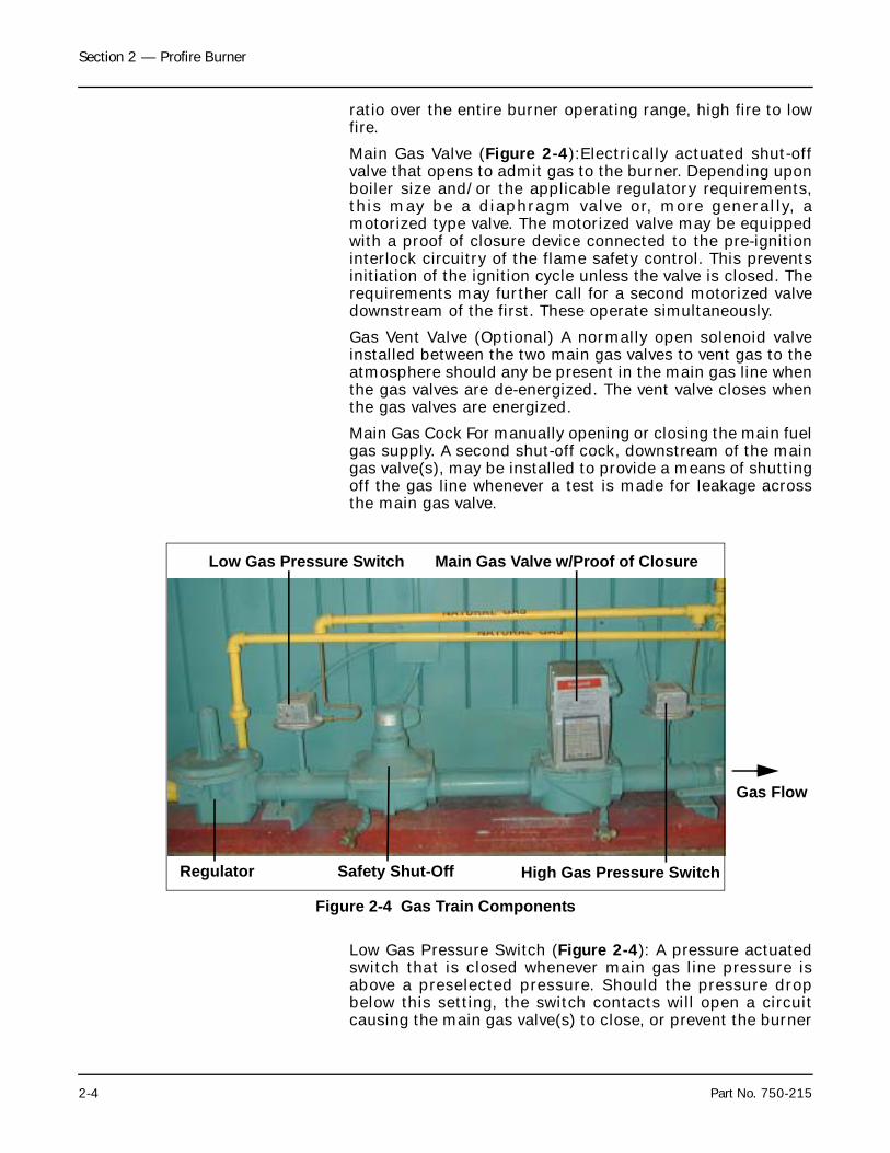
Main Gas Valve (Figure 2-4):Electrically actuated shut-offvalve that opens to admit gas to the burner. Depending uponboiler size and/or the applicable regulatory requirements,this may be a diaphragm valve or, more generally, amotorized type valve. The motorized valve may be equippedwith a proof of closure device connected to the pre-ignitioninterlock circuitry of the flame safety control. This preventsinitiation of the ignition cycle unless the valve is closed. Therequirements may further call for a second motorized valvedownstream of the first. These operate simultaneously.
Gas Vent Valve (Optional) A normally open solenoid valveinstalled between the two main gas valves to vent gas to theatmosphere should any be present in the main gas line whenthe gas valves are de-energized. The vent valve closes whenthe gas valves are energized.
Main Gas Cock For manually opening or closing the main fuelgas supply. A second shut-off cock, downstream of the maingas valve(s), may be installed to provide a means of shuttingoff the gas line whenever a test is made for leakage acrossthe main gas valve.
Low Gas Pressure Switch (Figure 2-4): A pressure actuatedswitch that is closed whenever main gas line pressure isabove a preselected pressure. Should the pressure dropbelow this setting, the switch contacts will open a circuitcausing the main gas valve(s) to close, or prevent the burner
Figure 2-4 Gas Train Components
Regulator
Low Gas Pressure Switch
Safety Shut-Off
Main Gas Valve w/Proof of Closure
High Gas Pressure Switch
Gas Flow
Section 2 — Profire Burner
Part No. 750-215 2-5
from starting. This switch is usually equipped with a devicethat must be manually reset after being tripped.
High Gas Pressure Switch (Figure 2-4): A pressure actuatedswitch that is closed whenever main gas line pressure isbelow a preselected pressure. Should the pressure rise abovethe setting, the switch contacts will open a circuit causingthe main gas valve(s) to close, or prevent the burner fromstarting. The switch is usually equipped with a device thatmust be manually reset after being tripped.
Leakage Connection. The body of the gas valve has a pluggedopening that is used whenever it is necessary or desirous toconduct a test for possible leakage across the closed valve.
D.OIL COMPONENTSOil Pump (Figure 2-3). The oil pump provided for oil burningis coupled to an extension of the combustion air fan shaft.
Oil Metering Valve (Figure 2-3). The oil metering valveregulates the flow rate of oil into the burner. The oil meteringvalve is connected by linkage and a jack shaft to themodulating motor, which provides the rotary motion to openand close the valve.
Oil Solenoid Valves (Figure 2-3). The oil solenoid valves arein series and downstream of the oil metering valve in thesupply line to the oil burner assembly. Two valves areprovided. These valves are simultaneously energized to openand release fuel oil to the burner. The valves close to stopcombustion when oil is the fuel.
Low Oil Pressure Switch.
E. IGNITION COMPONENTSIgnition Transformer (Figure 2-1). The ignition transformerproduces the high voltage required for spark generation bythe pilot electrode(s).
Pilot Gas Train (Figure 2-1). The standard pilot gas trainconsists of a manual stopcock, a gas pressure regulator, anda solenoid-operated gas shut-off valve. The gas pilot valveassembly controls a relatively small flow rate of natural gasto operate the gas-electric pilot.
Gas Pilot Shut-Off Cock For manually opening or closing thegas supply to gas pilot valve.
Gas Pressure Gauge Indicates gas pressure to pilot.(Optional)
Gas Pressure Regulating Valve Reduces incoming gaspressure to a value that assures a satisfactory pilot.
Section 2 — Profire Burner
2-6 Part No. 750-215
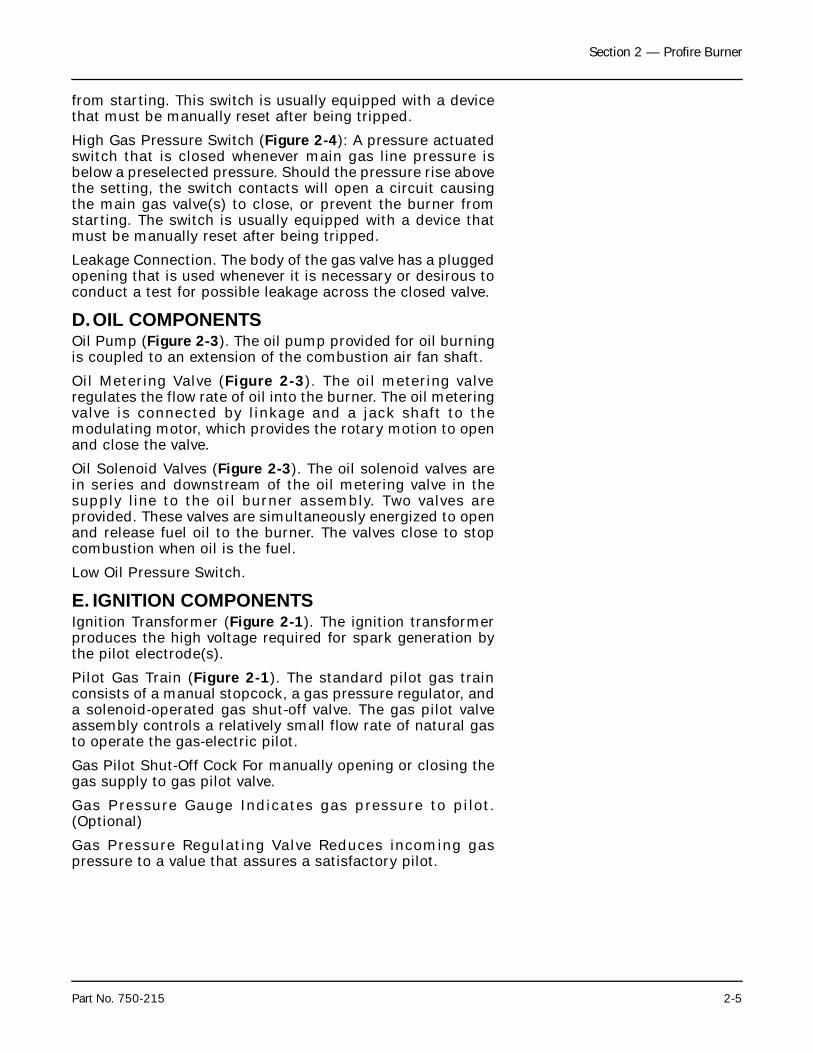
F. SAFETY AND CONTROLSFlame Safety (Figure 2-5, A): The flame safeguard controlsthe operating sequences of the combustion system(prepurge, pilot, firing, and shutdown). The control alsomonitors the flame, using a scanner which is sensitive tospecific flame frequencies. The flame safeguard alsoautomatically shuts down the burner when the flame signalbecomes too weak. Different types of flame safeguarddevices can be installed in the combustion systems. Checkthe wiring diagram for your burner for information on thespecific unit installed on your burner.
Fuel Selector Switch (Figure 2-5, B): Allows the operator toselect either gas or oil as the active fuel on combinationburners.
Combustion Air Proving Switch (Figure 2-1). The combustionair proving switch provides confirmation to the flamesafeguard that the combustion air fan is providing air flow.The fuel supply valves will not open if this switch does notsense adequate air pressure.
Modulating Motor (Figure 2-3). The modulating motor iscoupled to the jack shaft that operates the main air shutterand the fuel valve linkages. The modulating motor producesthe torque and rotary positioning required for firing ratecontrol.
Rear Cap (Figure 2-3). The rear cap contains the lockingsetscrew for adjustment of the diffuser relative to the airbaffle, and also the flame scanner for the flame safeguard.The rear cap must be removed to enable removal of the oilgun assembly.
The actual controls furnished with any given boiler willdepend upon the type of fuel for which it is equipped.
Boilers having optionally ordered features may have controlcomponents not listed here.
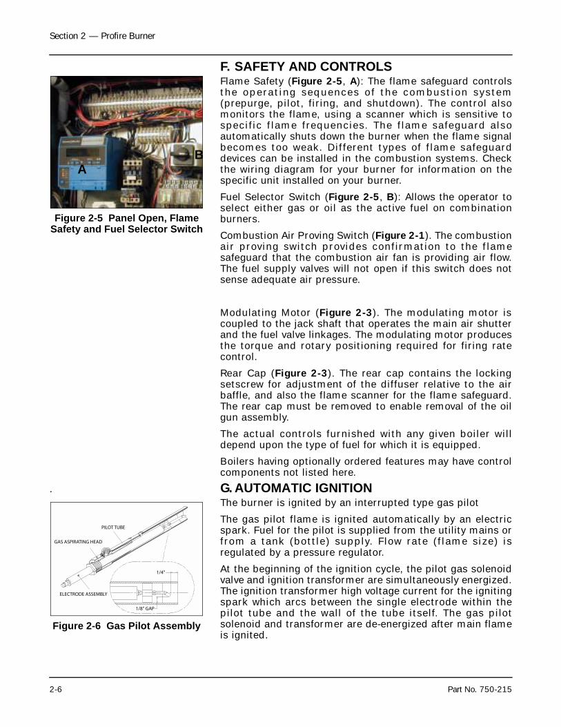
. G. AUTOMATIC IGNITION The burner is ignited by an interrupted type gas pilot
The gas pilot flame is ignited automatically by an electricspark. Fuel for the pilot is supplied from the utility mains orfrom a tank (bottle) supply. Flow rate (flame size) isregulated by a pressure regulator.
At the beginning of the ignition cycle, the pilot gas solenoidvalve and ignition transformer are simultaneously energized.The ignition transformer high voltage current for the ignitingspark which arcs between the single electrode within thepilot tube and the wall of the tube itself. The gas pilotsolenoid and transformer are de-energized after main flameis ignited.
Figure 2-5 Panel Open, Flame Safety and Fuel Selector Switch
AB
Figure 2-6 Gas Pilot Assembly
ELECTRODE ASSEMBLY
PILOT TUBE
GAS ASPIRATING HEAD
1/4"
1/8" GAP
Section 2 — Profire Burner
Part No. 750-215 2-7
H.COMBUSTION AIR Air for the combustion of fuel is delivered by the forced draftfan of the burner.
The supply of combustion air is regulated by modulating theair damper to maintain the correct ratio of air to fuel forefficient combustion throughout the range of firing rates.
I. OPERATION - NATURAL GASThe gas flow system is shown with the direction of flowindicated by the arrow. (Figure 2-4)
Metered gas from the utility flows into the burner’s gaspiping through a main gas shut-off cock; through a pressureregulator where the pressure is reduced to the pressuresuitable to the burner’s requirements; through an electricallyoperated main gas valve and through a butterfly gas valve tothe burner. Gas required for pilot operation is taken from thisline prior to the main gas shut-off cock.
Gas for the pilot operation flows through a shut-off cock intoa pressure regulator where the pilot operating pressure isestablished. A solenoid valve controls the flow of the gas andwhen energized (opened) allows the gas to flow to the pilotwhere it is mixed with combustion air. This mixture is ignitedby a controlled electric spark to establish the pilot flame.The pilot burns only during the time required for main flameignition.
At the beginning of the ignition cycle, the pilot solenoid valveis energized through circuitry in the programmer control andthe pi lot ignited. When pi lot f lame is proven, theprogramming control energizes the electrically operatedmain gas valve, allowing flow through the butterfly valve tothe burner. The rate of flow to the burner depends upon theposit ion of the vane in the butterf ly valve. This ismechanically controlled by the modulating motor and variedin the same manner as the air damper, thus properlyproportioning gas and combustion air.
The gas pressure regulator’s diaphragm and valve positionsitself to the degree required to maintain a constant pressureon its downstream side. The pressure to which its spring isset reduces the incoming pressure to prevent over-firingwhile still providing the volume of gas required by the burnerand at a pressure high enough to overcome the pressure lossdue to the frictional resistance imposed by the burnersystem and the control valves.
Gas flows through the burner orifice ring to enter thecombustion zone where it is intimately mixed withcombustion air to produce main flame.
The boiler has a modulating motor for controlling firing rate.This type of motor is reversible and will move in eitherdirection or stop at any position within its range. Through alinkage arrangement it controls the air damper and fuel
Section 2 — Profire Burner
2-8 Part No. 750-215
valve(s) to maintain the air-fuel ratio throughout the firingrange.
The main fuel valve(s) cannot be energized (opened) unlessthe combustion air proving switch is closed to indicate asufficient supply of combustion air.
Some insurance requirements specify two main fuel valves.Additional requirements call for a normally open vent valveto be placed between them for venting gas should any bepresent in main gas line when main gas valves are de-energized. The vent valve closes when the main gas valvesopen.
Milwaukee, Wisconsin
www.cleaver-brooks.com
Section 3The Pressure Vessel
A. General . . . . . . . . . . . . . . . . . . . . . . . . . . . . . . . . . . . . . . . . . . . 3-2B. Construction . . . . . . . . . . . . . . . . . . . . . . . . . . . . . . . . . . . . . . . . 3-2C. Water Requirements . . . . . . . . . . . . . . . . . . . . . . . . . . . . . . . . . . 3-3
Hot Water Boiler . . . . . . . . . . . . . . . . . . . . . . . . . . . . . . . . . . . 3-3Air Removal . . . . . . . . . . . . . . . . . . . . . . . . . . . . . . . . . . . . . . 3-3Continuous Flow . . . . . . . . . . . . . . . . . . . . . . . . . . . . . . . . . . 3-3Multiple Boiler Installation . . . . . . . . . . . . . . . . . . . . . . . . . . . . 3-3Pressure Drop . . . . . . . . . . . . . . . . . . . . . . . . . . . . . . . . . . . . 3-3Pressure . . . . . . . . . . . . . . . . . . . . . . . . . . . . . . . . . . . . . . . . 3-4Steam Boiler . . . . . . . . . . . . . . . . . . . . . . . . . . . . . . . . . . . . . 3-4Feed Pump Operation . . . . . . . . . . . . . . . . . . . . . . . . . . . . . . . 3-4Minimum Boiler Water Temperature . . . . . . . . . . . . . . . . . . . . . 3-4
D. Water Treatment . . . . . . . . . . . . . . . . . . . . . . . . . . . . . . . . . . . . . 3-4Objectives of water treatment in general are: . . . . . . . . . . . . . . . 3-5
E. Cleaning . . . . . . . . . . . . . . . . . . . . . . . . . . . . . . . . . . . . . . . . . . 3-5F. Boil-Out of a New Unit . . . . . . . . . . . . . . . . . . . . . . . . . . . . . . . . 3-7G. Washing Out . . . . . . . . . . . . . . . . . . . . . . . . . . . . . . . . . . . . . . . 3-9
Steam Boiler . . . . . . . . . . . . . . . . . . . . . . . . . . . . . . . . . . . . . 3-9Hot Water Boiler . . . . . . . . . . . . . . . . . . . . . . . . . . . . . . . . . . 3-9Flushing of Pressure Vessel Interior . . . . . . . . . . . . . . . . . . . . . . 3-9
H. Blowdown — Steam Boiler . . . . . . . . . . . . . . . . . . . . . . . . . . . . . 3-9Types of Blowdown . . . . . . . . . . . . . . . . . . . . . . . . . . . . . . . 3-10Intermittent Blowdown . . . . . . . . . . . . . . . . . . . . . . . . . . . . . 3-10Continuous Blowdown . . . . . . . . . . . . . . . . . . . . . . . . . . . . . 3-11Frequency of Intermittent Blowdown . . . . . . . . . . . . . . . . . . . . 3-11Manual Blowdown Procedure . . . . . . . . . . . . . . . . . . . . . . . . 3-12
I. Periodic Inspection . . . . . . . . . . . . . . . . . . . . . . . . . . . . . . . . . . 3-12J. Fireside Cleaning . . . . . . . . . . . . . . . . . . . . . . . . . . . . . . . . . . . 3-14K. Water Washing — Fireside (Oil Fired Unit) . . . . . . . . . . . . . . . . . 3-15L. Preparation for Extended Lay-Up . . . . . . . . . . . . . . . . . . . . . . . . 3-16
Dry Storage . . . . . . . . . . . . . . . . . . . . . . . . . . . . . . . . . . . . . 3-16Wet Storage . . . . . . . . . . . . . . . . . . . . . . . . . . . . . . . . . . . . . 3-16
Section 3 — The Pressure Vessel
3-2 Part No. 750-215
A.GENERALThis chapter is devoted primarily to the waterside care of thepressure vessel.
The operator must familiarize himself with this chapterbefore attempting to place the unit into operation.
Waterside care is of prime importance. The subject of watersupply and treatment cannot adequately be covered in thismanual. The services of a feedwater consultant should beobtained and their recommendations followed.
Water treatment is a must and has an important bearing onthe type of service your boiler provides. This is true for bothsteam and hot water boilers. It is essential to boiler life andlength of service. Constant attention to this area will paydividends in the form of longer life, less down time, andprevention of costly repairs. Care taken in placing thepressure vessel into initial service is vital. The waterside ofnew boilers and new or remodeled steam or hot watersystems may contain oil, grease or other foreign matter. Amethod of boi l ing out the vessel to remove theseaccumulations is described later in this chapter.
Feedwater equipment should be checked and ready for use.See that all valves, piping, boiler feed pump, and receiver areinstalled in accordance with prevailing codes and practices.
If the boiler is to be used for temporary heat, as for examplein new construction, properly treated water must be used.Failure to do so can be detrimental to the boiler.
Boilers, as part of a hot water system, require propercirculation and the system must be operated as intended byits designer to avoid severe, possibly damaging, stressesoccurring to the pressure vessel. Refer to Section of thischapter.
B.CONSTRUCTIONAll Cleaver-Brooks boi lers are bui l t to ASME Coderequirements and may be identified by the Code symbolstamped on the pressure vessel. indicates powerboilers: indicates heating boilers.
Heating boilers are defined as low pressure steam boilers foroperation at pressures not exceeding 15 psi and/or hotwater boilers operating at pressures not exceeding 160 psiand/or t empera tu res not exceed ing 250°F : andmanufactured to the ASME heating boiler Code.
Power boilers are steam boilers designed for pressures inexcess of 15 psi or high temperature water boilers operatingin excess of 250°F; and manufactured to the ASME powerboiler Code.
SH
Section 3 — The Pressure Vessel
Part No. 750-215 3-3
C.WATER REQUIREMENTS
1. Hot Water BoilerAir RemovalAll Cleaver-Brooks hot water boiler outlet connectionsinclude a dip tube which extends into the top drum. This diptube reduces the possibility of any air (which may be trappedat the top of the drum) entering into the system.
Any oxygen or air that may be released in the boiler willcollect or be trapped at the top of the drum and will find itsway out of the boiler through the air vent tapping. Thistapping, on the top center line of the drum should be pipedinto the expansion or compression tank.
Continuous FlowIt is required that the system be piped and the controlsarranged so that there will be water circulation through theboiler under all operating conditions. The minimumcirculation is 1/2 to 1 gallon per minute per boilerhorsepower. Constant circulation through the boilereliminates the possibility of stratification and results in moreeven water temperature to the system. Constant circulationis mandatory for a boiler equipped with an internal coil. Ablend pump is included as standard constructionon M5 HotWater boilers.
Multiple Boiler InstallationWhen multiple boilers of equal or unequal size are used, caremust be taken to insure adequate flow through each. Ifbalancing cocks or orifice plates are used, a significantpressure drop (for example, 3 to 5 psi) must be taken acrossthe balancing device to determine required flow rates.
If care is not taken to insure adequate flow through theboilers this can result in wide variation of firing rate betweenthem.
Pressure DropThere will be a pressure drop of less than 9 feet head (1 psi – 2.31 ft. hd.) through all standardly equipped Cleaver-Brooks boilers operating in any system which has more thanthe 20°F. temperature drop. This drop will vary with boilersize. Consult factory for specific information.
Section 3 — The Pressure Vessel
3-4 Part No. 750-215
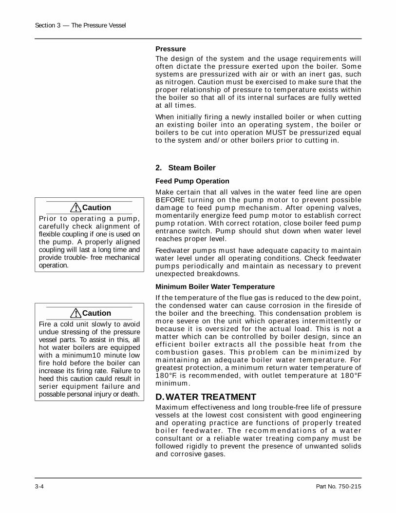
PressureThe design of the system and the usage requirements willoften dictate the pressure exerted upon the boiler. Somesystems are pressurized with air or with an inert gas, suchas nitrogen. Caution must be exercised to make sure that theproper relationship of pressure to temperature exists withinthe boiler so that all of its internal surfaces are fully wettedat all times.
When initially firing a newly installed boiler or when cuttingan existing boiler into an operating system, the boiler orboilers to be cut into operation MUST be pressurized equalto the system and/or other boilers prior to cutting in.
2. Steam BoilerFeed Pump OperationMake certain that all valves in the water feed line are openBEFORE turning on the pump motor to prevent possibledamage to feed pump mechanism. After opening valves,momentarily energize feed pump motor to establish correctpump rotation. With correct rotation, close boiler feed pumpentrance switch. Pump should shut down when water levelreaches proper level.
Feedwater pumps must have adequate capacity to maintainwater level under all operating conditions. Check feedwaterpumps periodically and maintain as necessary to preventunexpected breakdowns.
Minimum Boiler Water TemperatureIf the temperature of the flue gas is reduced to the dew point,the condensed water can cause corrosion in the fireside ofthe boiler and the breeching. This condensation problem ismore severe on the unit which operates intermittently orbecause it is oversized for the actual load. This is not amatter which can be controlled by boiler design, since anefficient boiler extracts all the possible heat from thecombustion gases. This problem can be minimized bymaintaining an adequate boiler water temperature. Forgreatest protection, a minimum return water temperature of180°F. is recommended, with outlet temperature at 180°Fminimum.
D.WATER TREATMENTMaximum effectiveness and long trouble-free life of pressurevessels at the lowest cost consistent with good engineeringand operating practice are functions of properly treatedboi ler feedwater. The recommendations of a waterconsultant or a reliable water treating company must befollowed rigidly to prevent the presence of unwanted solidsand corrosive gases.
! CautionPrior to ope rat ing a pump,carefully check alignment offlexible coupling if one is used onthe pump. A properly alignedcoupling will last a long time andprovide trouble- free mechanicaloperation.
! CautionFire a cold unit slowly to avoidundue stressing of the pressurevessel parts. To assist in this, allhot water boilers are equippedwith a minimum10 minute lowfire hold before the boiler canincrease its firing rate. Failure toheed this caution cauld result inserier equipment failure andpossable personal injury or death.
Section 3 — The Pressure Vessel
Part No. 750-215 3-5
Objectives of water treatment in general are:1. Prevention of hard scale deposits or soft sludge deposits
which impair the rate of heat transfer and can lead to overheated metal and costly down time and repairs.
2. Elimination of corrosive gases such as oxygen and carbon dioxide in the supply or boiler water.
3. Prevention of intercrystalline cracking or caustic embrittlement of boiler metal.
4. Prevention of carryover and foaming.
The accomplishment of these objectives generally requireproper feedwater treatment before and after introduction ofthe water into the boiler. The selection of pre-treatmentprocesses depends upon the water source, its chemicalcharacteristics, amount of make-up water needed, plantoperating practices, etc. These treating methods includefiltering, softening, de-mineralizing, derating and pre-heating. After treatment involves chemical treatment of theboiler water.
Because of the variables involved, no one “boiler compound”can be considered a “cure-all” nor is it advisable toexperiment with homemade treating methods. Soundrecommendations and their employment should beaugmented by a periodic analysis of the feedwater, boilerwater, and condensate.
The internal or waterside surfaces of the pressure vesselshould be inspected with sufficient frequency to determinethe presence of any contamination, accumulations of foreignmatter, of corrosion and/or pitting. If these conditions aredetected the water consultant or feedwater treatingcompany should be consulted for advice on correctiveaction.
It is recommended that a properly sized water meter beinstalled in the raw water make-up line to accuratelydetermine the amount of raw water admitted to the boiler(steam or hot water) to aid the water treatment program inmaintaining proper waterside conditions.
The general feeling exists that a hot water boiler does notrequire water treatment, but this is a false assumption. Therecommendations of a reliable water treating company or awater consultant should be followed rigidly. Even thoughthese generally operate on a closed system and blowdown isseldom practiced, the need remains to be alert to systemwater losses. A water meter is recommended for watermake-up lines.
E. CLEANING• Hot Water and Steam Piping
Steam and water piping systems connected to the boilermay contain oil, grease or foreign matter. These impurities
Section 3 — The Pressure Vessel
3-6 Part No. 750-215
must be removed to prevent damage to pressure vesselheating surfaces. On steam systems the condensate shouldbe wasted until tests show the elimination of undesirableimpurities. During the period that condensate is wasted,attention must be given to the treatment of the raw waterused as make up so that an accumulation of unwantedmaterials or corrosion does not occur. Follow the advice ofyour water treating company.
On hot water systems, chemical cleaning is generallynecessary and the entire system should be drained aftertreatment. Consult water treatment companies forrecommendations, cleaning compounds and applicationprocedures.
• Pressure Vessel
The waterside of the pressure vessel must be kept clean fromgrease, sludge and foreign material. Such deposits ifpresent, will not only shorten the life of the pressure vesseland interfere with efficient boiler operation and functioningof control or safety devices, but might quite possibly causeunnecessary and expensive re-work, repairs and down time.
The pressure vessel and the steam and return lines or hotwater piping represent, in effect, a closed system. Althoughthe steam and return (condensate) lines or the hot waterpiping system may have been previously cleaned it ispossible that:
1. Cleaning has been inadequate.
2. Partial or total old system is involved.
3. Conditions may prevent adequate cleaning of piping.
The installation and operating conditions to which the boilerwill be subjected must be considered and the cleaning of thewaterside of the pressure vessel must be provided during thecourse of initial start-up.
The pressure vessel waterside must be inspected on aperiodic basis. This will reveal true internal conditions andserve as a check against conditions indicated by chemicalanalysis of the boiler water. Inspection must be made threemonths after initial starting and at regular six monthintervals thereafter. The frequency of further periodicinspections wil l however depend upon the internalconditions found.
If any unwanted conditions are observed, your waterconsultant or water treating company must be contacted forrecommendations.
Any sludge, mud or sediment found must be flushed out. Theeffectiveness of the blowdown practiced on steam boilers willbe verified and scheduling or frequency of blowdown mayhave to be revised. The need for periodic draining or washoutwill also be indicated.
Section 3 — The Pressure Vessel
Part No. 750-215 3-7
Any oil or grease present on the heating surfaces must beremoved promptly by a boil-out with an alkaline detergentsolution.
F. BOIL-OUT OF A NEW UNITThe internal surfaces of a newly installed boiler may have oil,grease or other coatings for various reasons beyond themanufacturer’s control. These coatings must be removedsince they lower the heat transfer rate and could causeoverheating of heating surfaces. Before boil ing outprocedures may begin, the burner must be ready for firing.The operator must be familiar with the procedure outlinedunder burner operation.
Your water consultant or water treating company will be ableto recommend a cleaning or boil-out procedure. In the eventsuch service is unavailable or is yet unselected, the followinginformation may be of assistance.
Suggested procedure for boiling out new units prior to initialfiring is as follows:
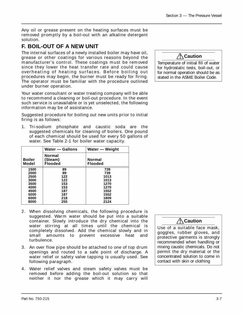
1. Tri-sodium phosphate and caustic soda are thesuggested chemicals for cleaning of boilers. One poundof each chemical should be used for every 50 gallons ofwater. See Table 2-1 for boiler water capacity.
2. When dissolving chemicals, the following procedure issuggested. Warm water should be put into a suitablecontainer. Slowly introduce the dry chemical into thewater stirring at all times until the chemical iscompletely dissolved. Add the chemical slowly and insmall amounts to prevent excessive heat andturbulence.
3. An over flow pipe should be attached to one of top drumopenings and routed to a safe point of discharge. Awater relief or safety valve tapping is usually used. Seefollowing paragraph.
4. Water relief valves and steam safety valves must beremoved before adding the boil-out solution so thatneither it nor the grease which it may carry will
! CautionTemperature of initial fill of waterfor hydrostatic tests, boil-out, orfor normal operation should be asstated in the ASME Boiler Code.
BoilerModel
Water — Gallons Water — WeightNormal(Steam)Flooded
NormalFlooded
1500200025003000350040004500500060008000
8989
122122153153187187218255
739739
10131013127012701552155218092124
! CautionUse of a suitable face mask,goggles, rubber gloves, andprotective garments is stronglyrecommended when handling ormixing caustic chemicals. Do notpermit the dry material or theconcentrated solution to come incontact with skin or clothing
Section 3 — The Pressure Vessel
3-8 Part No. 750-215
contaminate these valves. Use care in removing and re-installing valves.
5. All valves in the piping leading to or from the systemmust be closed to prevent cleaning solution from gettinginto the system.
6. Fill pressure vessel with clean water until top of tubeopenings in upper drum are covered. Add the cleaningsolution and then fill to the top.
7. The boiler should then be fired intermittently at a lowrate sufficient to hold solution just at the boiling point.Boil the water for at least 5 hours. Do not producesteam pressure.
8. Allow a small amount of fresh water to enter boiler tocreate a slight overflow that will carry off surfaceimpurities.
9. Continue boiling and overflow until water clears.
10. Stop the burner and drain boiler using caution that thehot water is discharged with safety.
11. Remove cover plate in upper drum and inspection plugsin lower drum and wash the waterside surfacesthoroughly using a high pressure water stream.
12. Inspect surfaces and if not clean repeat the boil-out.
13. After closing openings and re-installing safety or reliefvalve(s), fill the boiler and fire until water is heated to atleast 180°F. to drive off any dissolved gases which mightotherwise corrode the metal.
The above procedure may be omitted in the case of unitspreviously used or known to be internally clean, however,cons iderat ion must be g iven to the possib i l i ty ofcontaminating materials entering the boiler from thesystem.
On a steam system the condensate should be wasted untiltests show the elimination of undesirable impurities. Duringthe period that condensate is wasted, attention must begiven to the treatment of the raw water used as make up sothat an accumulation of unwanted materials or corrosiondoes not occur. Follow the advice of your water treatingcompany.
On a hot water system chemical cleaning of the entiresystem is generally necessary and the entire system shouldbe drained after treatment. Consult a water treatmentcompany for recommendations, cleaning compounds andapplication procedure.
Section 3 — The Pressure Vessel
Part No. 750-215 3-9
G. WASHING OUT
1. Steam BoilerNo later than 3 months after initially placing the boiler intooperation and thereafter as conditions warrant, the pressurevessel should be drained after being properly cooled to nearambient temperature, handhole cover or closure plate in theupper drum and handhole covers in the lower drum removedand internal waterside surfaces inspected for corrosion,pitting, or formation of deposits.
2. Hot Water BoilerIn theory, a hot water system and boiler that has beeninitially cleaned, filled with treated water, and with no make-up water added will require no further cleaning or treatment.However, since the system (new or old) may allow entranceof air and unnoticed or undetected leakage of water,introductions of raw water make-up or air may lead topitting, corrosion and formation of sludge, sediment, scale,etc., on the pressure vessel waterside.
If there is any doubt then the pressure vessel watersideshould be inspected no later than 3 months after initiallyplacing the boiler into operation and periodically thereafteras indicated by conditions observed during inspections.
Flushing of Pressure Vessel InteriorUpon completion of inspection, the pressure vessel interiorshould be flushed out as required with a high pressure hose.If deposits are not fully removed by such flushing, this mayrequire immediate consultation with your water consultantor feedwater treatment company, and in extreme cases, itmay be necessary to resort to acid cleaning. Professionaladvice is recommended if acid cleaning is required.
These inspections will indicate the effectiveness of thefeedwater treatment. The effectiveness of treatment, thewater conditions, and the amount of fresh water make-uprequired are all factors to be considered in establishingfrequency of future pressure vessel wash-out periods.Subsequent inspections will indicate the effectiveness of thewater treating program as well as the suitability of theintervals between washouts. The feedwater consultant orwater treatment company service should include periodicpressure vessel inspection and water analysis.
H.BLOWDOWN — STEAM BOILERBoiler water blowdown is the removal of some of theconcentrated water from the pressure vessel and itsreplacement with feedwater so that a lowering of theconcentration in the boiler water occurs.
Solids are present in the feedwater even though this water istreated prior to use with external processes that are
Section 3 — The Pressure Vessel
3-10 Part No. 750-215
designed to remove unwanted substances which contributeto scale and deposit formations. However, none of theseprocesses are in themselves capable of removing allsubstances and regardless of their high efficiency, a smallamount of encrusting solids will be present in the boilerwater.
Solids become less soluble in the high temperature of theboiler water and tend to crystallize and concentrate onheating surfaces. Internal chemical treatment is, therefore,required to prevent the solids from forming harmful scaleand sludge.
Scale has a low heat transfer valve and acts as an insulationbarrier. This retards heat transfer, which not only results inlower operating efficiency and consequently higher fuelconsumption, but, more importantly can cause overheatingof boiler metal.
This can result in tube failures or other pressure vessel metaldamage causing boiler down time and costly repairs.
Scale is caused primarily by calcium and magnesium saltsand silica. Any calcium and magnesium salts in the boilerwater are generally precipitated by the use of sodiumphosphate along with organic materials to maintain theseprecipitates or “sludge” in a fluid form. The solids such assodium salts and suspended dirt do not readily form scale,but as the boiler water boils off as relatively pure steam, theremaining water is thicker with the sol ids. I f th isconcentration is permitted to accumulate, foaming andpriming will occur and the sludge can cause harmfuldeposits that bring about overheating of the metal.
The lowering or removal of this concentration requires theuse of boiler water blowdown.
1. Types of BlowdownThere are two principal types of blowdown: intermittentmanual blowdown and continuous blowdown.
Intermittent BlowdownManual or sludge blowdown is necessary for the operation ofthe boiler regardless of whether or not continuous blowdownis employed.
The blowdown tapping is located in the bottom drum. Inaddition to lowering the dissolved solids in the pressurevessel water, blowdown also removes a portion of the sludgewhich accumulates in the lower drum.
Equipment generally consists of a quick opening valve and ashut-off valve. These, along with the necessary piping, arenot normally furnished with the boiler, but supplied byothers. All piping must be to a safe point of discharge. Pipingmust be properly supported and free to expand.
! CautionBoiler and water level controlblowdown must be performed ona regular basis to ensure thatconsentrated solids are removedfrom the boiler and in order toavoid damage to the equipment
Section 3 — The Pressure Vessel
Part No. 750-215 3-11
Continuous BlowdownContinuous blowdown is used in conjunction with a surfaceblow-of f tapping and is the continuous removal ofconcentrated water.
The surface blow-off opening, located in the rear head of theupper drum, is slightly below the working water level for thepurpose of skimming surface sediment, oil or otherimpurities from the surface of the pressure vessel water.
A controlled orifice valve is used to allow a continual — yetcontrolled — flow of concentrated water.
Periodic adjustments are made to the valve setting toincrease or decrease the amount of blowdown in accordancewith test analysis.
The flow control valve and piping are generally provided byothers. All piping must be to a safe point of discharge.
2. Frequency of Intermittent BlowdownWhen continuous blowdown is util ized, intermittentblowdown is primarily used to remove suspended solids orsludge. The continuous blowdown removes sediment and oilfrom the surface of the water along with a prescribed amountof dissolved solids.
When surface or continuous blowdown is not utilized,manual blowdown is used to control the dissolved orsuspended solids in addition to the sludge.
In practice, the valve(s) of the bottom blowdown are openedperiodically in accordance with an operating schedule and/or chemical control tests. From the standpoint of control,economy and results, frequent short blows are preferred toinfrequent lengthy blows. This is particularly true whensuspended solids content of the water is high. With the useof frequent short blows a more uniform concentration of thepressure vessel water is maintained.
In cases where the feedwater is exceptionally pure, or wherethere is a high percentage of return condensate, blowdownmay be employed less frequently since less sludgeaccumulates in the pressure vessel. When dissolved and/orsuspended solids approach or exceed pre-determined limits,manual blowdown to lower these concentrations is required.
It is generally recommended that steam boilers be blowndown at least once in every eight hour period, but this mayvary depending upon water and operating conditions. Theblowdown amounts and a schedule should be recommendedby a water treating company or a water consultant.
A hot water boiler does not normally include a tapping forsurface blowdown but does have a drain opening in the lowerdrum. Blowdown is not commonly practiced with a hot watersystem, however may be necessary depending upon thecondition of system, variable water and make-up. The need
Section 3 — The Pressure Vessel
3-12 Part No. 750-215
remains to be a l e r t to sys tem wate r l osses andcorresponding amount of raw water make-up. A water meterwith a small flow rate is recommended for water make-uplines.
3. Manual Blowdown ProcedureBlowdown is most effective at a time when generation ofsteam is at the lowest rate since feedwater input then is alsolow, providing a minimum dilution of the boiler water withlow concentration feedwater.
Make sure blow-off piping, and tank, if used, are in properoperating condition and discharge vents clear of obstruction,and that waste is piped to a point of safe discharge. The valveinstallation must be in accordance with applicable codes.
Most blow-off lines are provided with two valves, generally aquick opening valve nearest the boiler and a slow openingglobe type valve downstream. Two slow opening valves ortandem valves may be used. Valves will vary depending uponpressure involved and make or manufacture.
If a quick opening valve and a globe type or slow openingvalve are in combination, the former is normally opened firstand closed last with blowing down accomplished with theglobe or slow opening valve. If seatless valves are installedfollow the manufacturer’s recommendations.
When opening the second or down stream valve, crack itslightly to allow the lines to warm up, then continue openingslowly.
The length of each blow should be determined by actualwater analysis. Lowering the water in the gauge glassapproximately 1/2" is often acceptable as a guide toadequate blow, however, this should not be interpreted as arule since water analysis procedures should prevail. If theglass cannot be viewed by the party operating the valve,another operator should watch the glass and direct the valveoperator.
Close the downstream (slow opening) valve first and as fastas possible. Then close the valve next to the boiler. Slightlycrack the downstream valve and then close it tightly.
A blow-off valve must not be left open and the operator mustnever leave until the blowdown operation is completed andthe valves closed.
I. PERIODIC INSPECTIONInsurance regulations or local laws will require a periodicinspection of the pressure vessel by an authorized inspector.Sufficient notice is generally given to permit removal fromservice and preparation for inspection.
When shutting down, the load should be reduced graduallyand the pressure vessel cooled at a rate that avoids
! WarningBe sure thwt the blowdown pipingis in good condition, the dischargevents are clear of obstruction, andthat the waste is piped to a safepoint of discharge, in order toavoid serious personal injury ordeath.
Section 3 — The Pressure Vessel
Part No. 750-215 3-13
damaging temperature differential that can cause harmfulstresses. Vessels should not normally be drained until allpressure is relieved again to prevent uneven contraction andtemperature differentials. Draining the unit too quickly maycause the baking of deposits that may be present on theheating surfaces. Some heat, however, may be desirable todry out the interior of the boiler.
If the internal inspection is being made at the request of anauthorized inspector, it is well to learn from him whether hedesires to observe the conditions prior to cleaning orflushing of waterside surfaces.
Handhole openings are located in the drum heads. Theseopenings provide access and permit waterside inspection ofthe drum.
The handhole plates should be tightened securely to preventleakage. Always use a new gasket when resealing. Make surethat seating surfaces are clean. Snugging the nut after awarm-up period will help provide a tight seal.
Be certain that proper gaskets are available along with anyother items needed to place the unit back into operationafter inspection.
Have available information on the boiler design, dimensions,generating capacity, operating pressure or temperature,time in service, defects found previously and any repairs ormodifications. Also have available for reference records ofprevious inspections.
Be prepared to perform any testing required by the inspectorincluding hydrostatic.
After proper cooling and draining of vessel, flush out thewaterside with a high pressure water hose. Remove any scaleor deposits from the waterside surfaces and check forinternal or external corrosion and leakage.
The fireside surfaces should also be thoroughly cleaned sothat metal surfaces, welds, joints, etc. plus any previousrepairs can be readily checked. See Section .
Be sure that steam valves, system valves, (hot water)feedwater valves, blow-off valves, all fuel valves, valves toexpansion tanks, and electrical switches are shut off prior toopening inspection cover or removing plugs. Flashlightsrather than extension cords are recommended as a safetyfactor. Cleaners should preferably work in pairs.
Clean out the low water cut-off piping, the water levelcontrols and cross connecting piping. Replace water gaugeglass and clean out water cocks and tricocks.
Also check and clean drain and blowdown valves and piping.
Check all water and steam piping and valves for leaks, wear,corrosion and other damage. Replace or repair as required.
Section 3 — The Pressure Vessel
3-14 Part No. 750-215
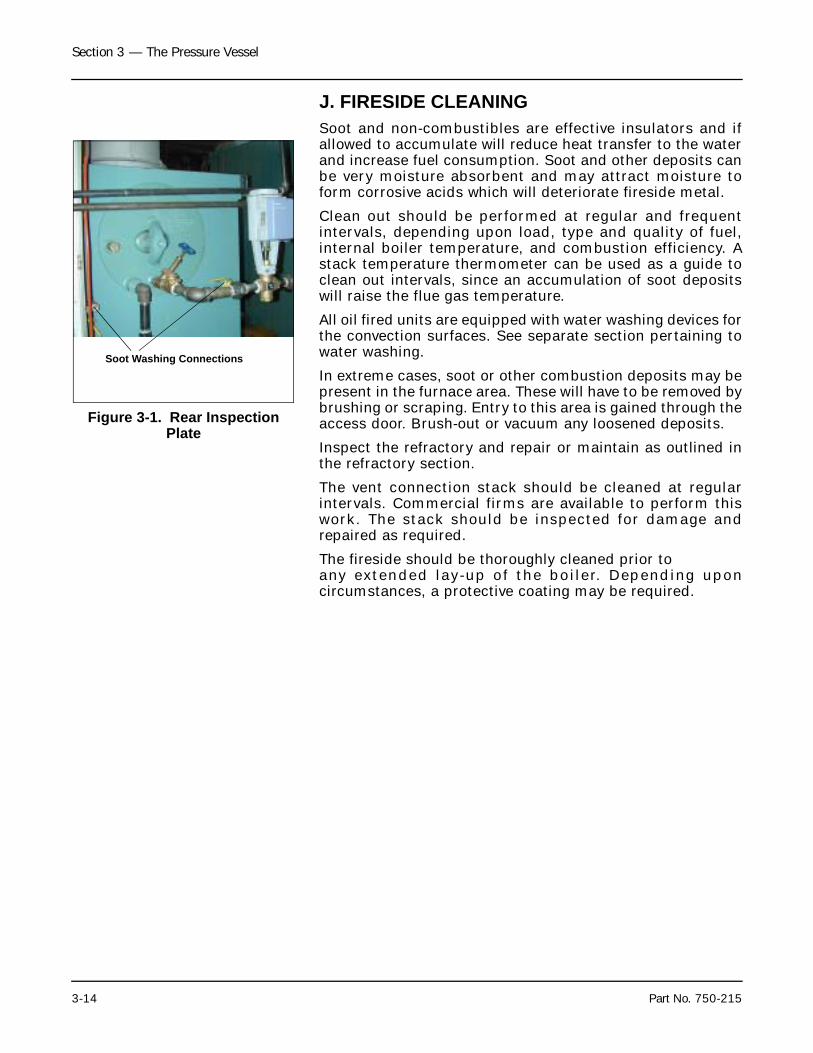
J. FIRESIDE CLEANINGSoot and non-combustibles are effective insulators and ifallowed to accumulate will reduce heat transfer to the waterand increase fuel consumption. Soot and other deposits canbe very moisture absorbent and may attract moisture toform corrosive acids which will deteriorate fireside metal.
Clean out should be performed at regular and frequentintervals, depending upon load, type and quality of fuel,internal boiler temperature, and combustion efficiency. Astack temperature thermometer can be used as a guide toclean out intervals, since an accumulation of soot depositswill raise the flue gas temperature.
All oil fired units are equipped with water washing devices forthe convection surfaces. See separate section pertaining towater washing.
In extreme cases, soot or other combustion deposits may bepresent in the furnace area. These will have to be removed bybrushing or scraping. Entry to this area is gained through theaccess door. Brush-out or vacuum any loosened deposits.
Inspect the refractory and repair or maintain as outlined inthe refractory section.
The vent connection stack should be cleaned at regularintervals. Commercial firms are available to perform thiswork. The stack should be inspected for damage andrepaired as required.
The fireside should be thoroughly cleaned prior to any extended lay-up of the boiler. Depending uponcircumstances, a protective coating may be required.
Figure 3-1. Rear Inspection Plate
Soot Washing Connections
Section 3 — The Pressure Vessel
Part No. 750-215 3-15
K.WATER WASHING — FIRESIDE (OIL FIRED UNIT)
An oil fired boiler has water washing lances located in thepassageway between the convection tube wall and thefurnace tube wall on both sides of the boiler (see Figures 3-1). Their purpose is to provide a means of washing away anysoot that may have built up on the tube wall surfaces. Thefrequency of water washing depends upon operatingconditions. Boilers with long operating runs at high fire andwith efficient flame will require less frequent cleaning thanthose with frequent cycling, prolonged low fire operation,improperly adjusted combustion, etc.
A periodic log of stack temperatures determined through useof a stack thermometer will alert the operator to the need forcleaning. A marked increase in temperature over anestablished level indicates a loss in efficiency and heattransfer caused by soot deposits.
A flexible hose from the building water supply should beattached to the hand operated valve on the lance. Do not useboiler feedwater. In the event permanent piping or tubing isprovided instead of a hose, a suitable swivel joint must beinstalled to allow rotation of the lance. A shutoff valve at thesupply point is recommended.
Remove the drain caps or fully open valves in the drain piping— depending upon installation. If drain piping is notprovided, the use of a drain hose is suggested. If the boileris situated adjacent to a drain it may be possible to merelylet the discharge wash water run into it. Thoroughly wet thefloor first to aid in floating away soot.
Bring the boiler up to its approximate operating pressure ortemperature before washing. With the burner in low fire,open one lance valve and rotate the lance in an arc thatassures washing panel surfaces. Note the reference mark onthe lance to indicate location of spray holes. Continuerotating back and forth until drain water runs clear. Openingand closing the valve to obtain frequent, short spraysprovides better results than a steady flow.
Care must be taken to be sure that water is draining away atapproximately the same rate as its input to avoid flooding orentering the furnace.
When drain water is clear, repeat the process in the otherbank. After washing, the close the lance valve and whendraining stops, shut the drain valves or replace caps.
To be sure that all moisture is evaporated, continue firing forat least 45 minutes after washing so that the convection areais thoroughly dried. During this drying period the burnermay be cycled to the high fire position.
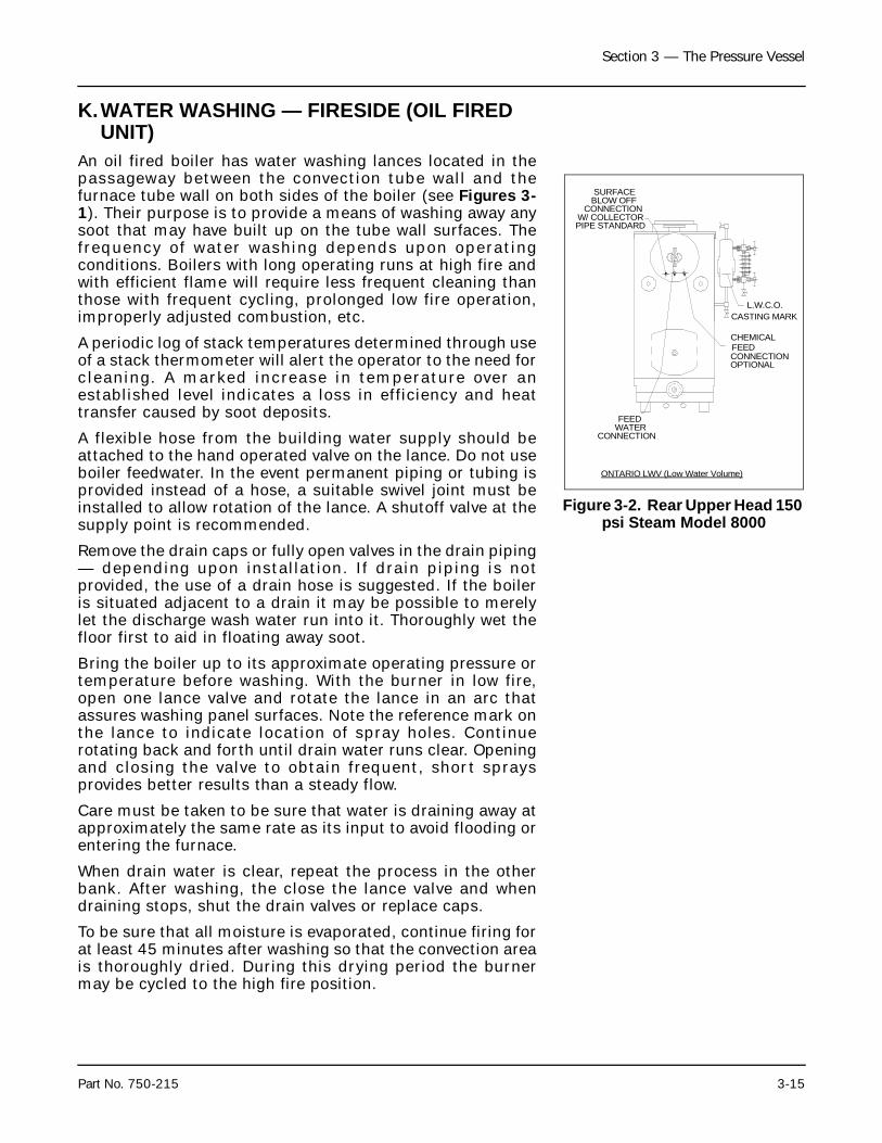
Figure 3-2. Rear Upper Head 150 psi Steam Model 8000
ONTARIO LWV (Low Water Volume)
SURFACEBLOW OFF
CONNECTIONW/ COLLECTORPIPE STANDARD
FEEDWATER
CONNECTION
CHEMICALFEEDCONNECTIONOPTIONAL
L.W.C.O.CASTING MARK
Section 3 — The Pressure Vessel
3-16 Part No. 750-215
The front end of the water drain troughs on the under side ofthe drum are equipped with capped openings. Theseopenings enable the trough to be flushed with a hose, ifnecessary, to remove any accumulation. When doing this,make sure that the drains are open and that water is drainingaway.
L. PREPARATION FOR EXTENDED LAY-UPA boiler used for heating or seasonal loads or for stand-byservice may have an extended period of non-use. Specialattention must be given so that neither waterside nor firesidesurfaces are allowed to deteriorate from corrosion.
There are two methods of storage — wet or dry. Your waterconsultant or feedwater treating company can recommendthe better method, depending upon circumstances in aparticular installation. Section VII of the ASME Code alsocontains information relating to laying up a boiler.
1. Dry StorageDry storage is generally employed when the boiler will be outof service for some time or when freezing temperatures mayoccur. In this method, the boiler must be thoroughly dried,since any moisture will cause corrosion. Both waterside andfireside surfaces must be clean of all scale and deposits,soot, etc. Steps must be taken to eliminate moisture byplacing moisture absorbing material, such as quicklime orsilica-gel, on trays inside the drums and furnace. These traysshould not be completely filled with the material, so that thecorrosion liquid gathered in them does not overflow onto theboiler surfaces. Refractories should be brushed clean andwash-coated. fireside surfaces may be sprayed or coatedwith an anti-corrosive material. All openings to pressurevessel must be shut tightly. Feedwater and steam valvesshould be closed. Damper and vents should be closed toprevent air from reaching fireside surfaces. Periodicinspection must be made and the absorption materialsrenewed.
Care must be taken to remove all of the moisture absorbingmaterial before any attempt is made to refill the boiler.Serious damage can result otherwise. As a precaution it isrecommended that warning signs be conspicuously posted.These signs could be similar to the following
2. Wet StorageWet storage is generally used for a boiler held in standbycondition or in a case where dry storage is not practical. Thepossibility of freezing temperatures must be considered.Care must be taken to protect metal surfaces. Variablespreclude definite recommendations, however, it is suggestedthat after the vessel is drained and cleaned that it be refilledto overflowing with treated water. If deaerated water is notavailable, the boiler should be fired to boil the water for a
Important!Moisture absorption material hasbeen placed in the waterside andfurnace areas of this boiler. Thismaterial must be removed beforeany water is placed in boiler andbefore burner is fired. Inspectperiodically and replace withf r esh and /o r r egene ra tedmaterials
Section 3 — The Pressure Vessel
Part No. 750-215 3-17
short period of time. Additional chemicals may be suggestedby the water consultant to minimize corrosion. Internalwater pressure should be maintained at greater thanatmospheric pressure. Nitrogen is often used for thispurpose. fireside surfaces must be thoroughly cleaned andrefractories should be wash-coated. It is advisable, iffeasible, to occasionally circulate the water to preventstratification and to insure that fresh inhibitor is in contactwith all the surfaces. If additional chemicals are added forthis idle period, more frequent blowdowns may be requiredwhen the boiler is returned to service to rapidly reduce thechemical composition to normal operating levels.
During storage, steps should be taken to protect the exteriorcomponents from the possibility of rust or corrosion. Theseparts should be coated with a rust inhibitor and protectedfrom moisture and condensation. Operating controls,regulators, valves, etc. should be drained and dried.Electrical equipment should likewise be protected. Keepingthe control circuit energized may prevent condensation fromforming in the control cabinet or on the flame safeguardcontrol.
Section 3 — The Pressure Vessel
3-18 Part No. 750-215
Notes
Milwaukee, Wisconsin
www.cleaver-brooks.com
Section 4Sequence Of Operation
A. General . . . . . . . . . . . . . . . . . . . . . . . . . . . . . . . . . . . . . . . . . . . 4-2B. Circuit and Interlock Controls . . . . . . . . . . . . . . . . . . . . . . . . . . . . 4-2C. Sequence of Operation - Oil or Gas . . . . . . . . . . . . . . . . . . . . . . . . 4-5D. Flame Loss Sequence . . . . . . . . . . . . . . . . . . . . . . . . . . . . . . . . . 4-7
Section 4 — Sequence Of Operation
4-2 Part No. 750-215
A.GENERALChapter 4 outlines the electrical sequencing of variouscontrols through the pre-purge, ignition, run, and shutdowncycles of the burner.
The program relay establishes the sequence of operationand directs the operation of all other controls andcomponents to provide an overall operating sequence.
Abbreviations for the various electrical components arelisted in Figure 4-1. The sequences outlined in Chapter 4employ specific nomenclature to aid in applying the text tothe wiring diagram.
The burner and control system are in starting conditionwhen the following conditions exist:
• Boiler water is up to the correct level, closing the low-water cutoffswitch.
• The low-water light (panel) is off.
• The operating limit pressure control (steam boiler) or the operatinglimit temperature control (hot water boiler) and high limit pressureor temperature control are below their cutoff setting.
• All applicable limits are correct for burner operation.
• The load demand light glows.
• All entrance switches are closed and power is present at the lineterminals of:
• Blower motor starter
• Oil pump motor starter (if provided).
The sequences do not attempt to correlate the action of thefuel supply system or feedwater system except for theinterlock controls that directly relate to the action of theprogram relay. Chapters 5 and 6 contain operatinginstructions and specific information on setting andadjusting the controls.
B.CIRCUIT AND INTERLOCK CONTROLSThe burner control circuit is a two-wire system designed for115 Vac, 60 Hz, single-phase power.
The electrical portion of the boiler is made up of individualcircuits with controls that are wired in a manner designed toprovide a safe workable system. The program relay providesconnection points for the interconnection of the variouscircuits.
The controls used vary depending upon the fuel oil or gasand the specific requirement of applicable regulatory bodies.Refer to the boiler wiring diagram to determine the actualcontrols provided. The circuits and controls normally used inthe circuits follow and are referred to in the followingsequence of operation.
NoticeThe m a ke o r mod e l o f th eprogram relay provided will varyde pe nd in g u pon j obspecifications. The followingsequence applies regardless ofthe make or model. Please referto the Wiring Diagram (WD)prepared by Cleaver-Brooks foryour specific installation.
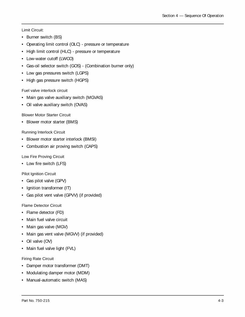
Section 4 — Sequence Of Operation
Part No. 750-215 4-3
Limit Circuit:
• Burner switch (BS)
• Operating limit control (OLC) - pressure or temperature
• High limit control (HLC) - pressure or temperature
• Low-water cutoff (LWCO)
• Gas-oil selector switch (GOS) - (Combination burner only)
• Low gas pressures switch (LGPS)
• High gas pressure switch (HGPS)
Fuel valve interlock circuit
• Main gas valve auxiliary switch (MGVAS)
• Oil valve auxiliary switch (OVAS)
Blower Motor Starter Circuit
• Blower motor starter (BMS)
Running lnterlock Circuit
• Blower motor starter interlock (BMSI)
• Combustion air proving switch (CAPS)
Low Fire Proving Circuit
• Low fire switch (LFS)
Pilot Ignition Circuit
• Gas pilot valve (GPV)
• Ignition transformer (IT)
• Gas pilot vent valve (GPVV) (if provided)
Flame Detector Circuit
• Flame detector (FD)
• Main fuel valve circuit
• Main gas valve (MGV)
• Main gas vent valve (MGVV) (if provided)
• Oil valve (OV)
• Main fuel valve light (FVL)
Firing Rate Circuit
• Damper motor transformer (DMT)
• Modulating damper motor (MDM)
• Manual-automatic switch (MAS)
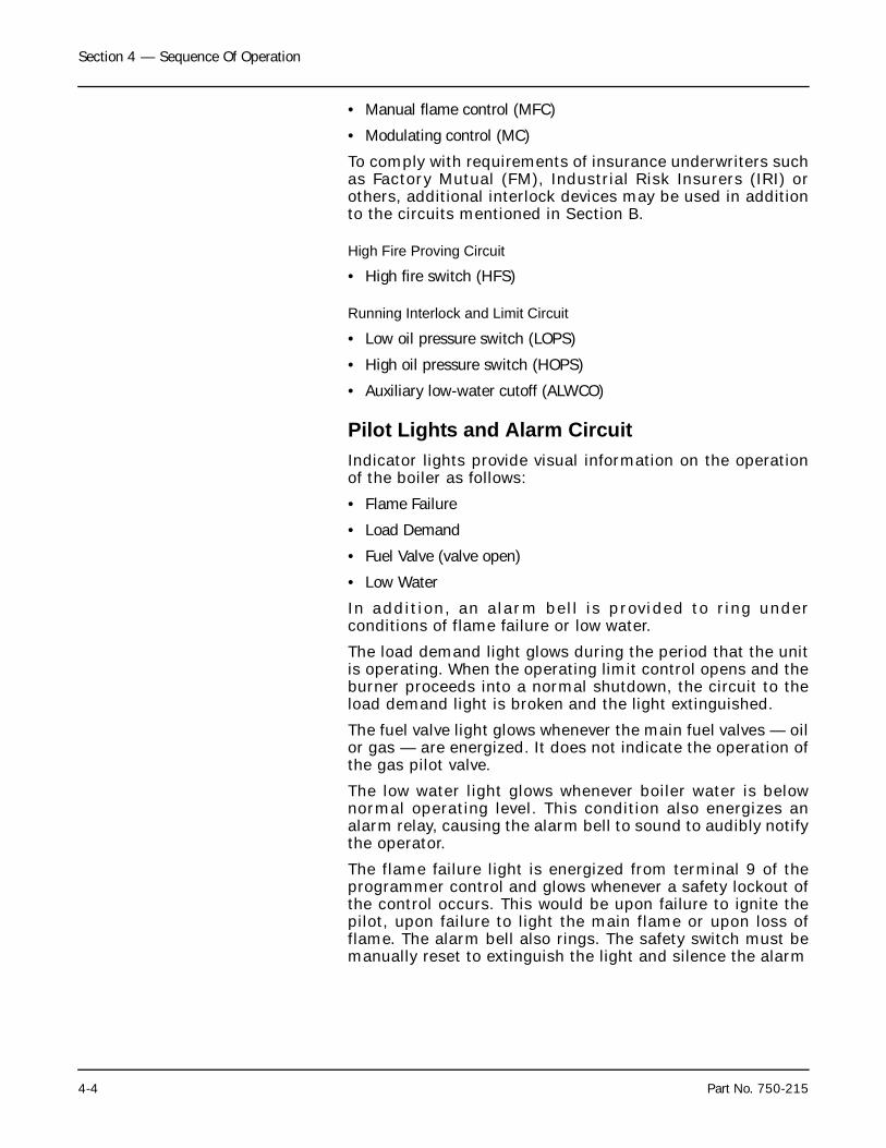
Section 4 — Sequence Of Operation
4-4 Part No. 750-215
• Manual flame control (MFC)
• Modulating control (MC)
To comply with requirements of insurance underwriters suchas Factory Mutual (FM), Industrial Risk Insurers (IRI) orothers, additional interlock devices may be used in additionto the circuits mentioned in Section B.
High Fire Proving Circuit
• High fire switch (HFS)
Running Interlock and Limit Circuit
• Low oil pressure switch (LOPS)
• High oil pressure switch (HOPS)
• Auxiliary low-water cutoff (ALWCO)
Pilot Lights and Alarm CircuitIndicator lights provide visual information on the operationof the boiler as follows:
• Flame Failure
• Load Demand
• Fuel Valve (valve open)
• Low Water
In addition, an alarm bell is provided to ring underconditions of flame failure or low water.
The load demand light glows during the period that the unitis operating. When the operating limit control opens and theburner proceeds into a normal shutdown, the circuit to theload demand light is broken and the light extinguished.
The fuel valve light glows whenever the main fuel valves — oilor gas — are energized. It does not indicate the operation ofthe gas pilot valve.
The low water light glows whenever boiler water is belownormal operating level. This condition also energizes analarm relay, causing the alarm bell to sound to audibly notifythe operator.
The flame failure light is energized from terminal 9 of theprogrammer control and glows whenever a safety lockout ofthe control occurs. This would be upon failure to ignite thepilot, upon failure to light the main flame or upon loss offlame. The alarm bell also rings. The safety switch must bemanually reset to extinguish the light and silence the alarm
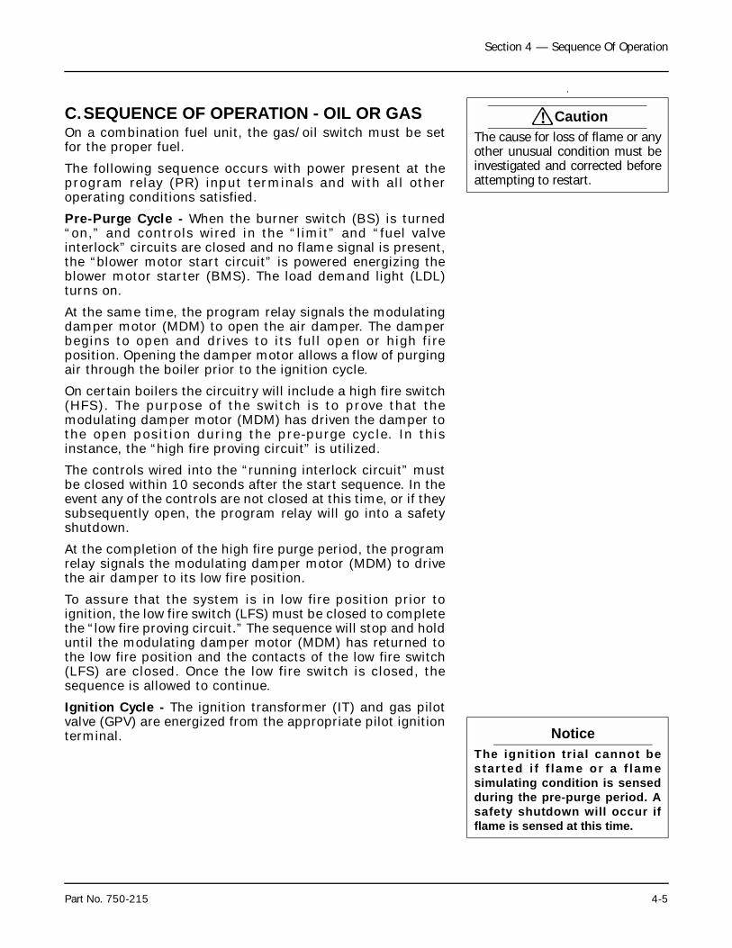
Section 4 — Sequence Of Operation
Part No. 750-215 4-5
.
C.SEQUENCE OF OPERATION - OIL OR GASOn a combination fuel unit, the gas/oil switch must be setfor the proper fuel.
The following sequence occurs with power present at theprogram relay (PR) input terminals and with all otheroperating conditions satisfied.
Pre-Purge Cycle - When the burner switch (BS) is turned“on,” and controls wired in the “limit” and “fuel valveinterlock” circuits are closed and no flame signal is present,the “blower motor start circuit” is powered energizing theblower motor starter (BMS). The load demand light (LDL)turns on.
At the same time, the program relay signals the modulatingdamper motor (MDM) to open the air damper. The damperbegins to open and drives to its full open or high fireposition. Opening the damper motor allows a flow of purgingair through the boiler prior to the ignition cycle.
On certain boilers the circuitry will include a high fire switch(HFS). The purpose of the switch is to prove that themodulating damper motor (MDM) has driven the damper tothe open position during the pre-purge cycle. In thisinstance, the “high fire proving circuit” is utilized.
The controls wired into the “running interlock circuit” mustbe closed within 10 seconds after the start sequence. In theevent any of the controls are not closed at this time, or if theysubsequently open, the program relay will go into a safetyshutdown.
At the completion of the high fire purge period, the programrelay signals the modulating damper motor (MDM) to drivethe air damper to its low fire position.
To assure that the system is in low fire position prior toignition, the low fire switch (LFS) must be closed to completethe “low fire proving circuit.” The sequence will stop and holduntil the modulating damper motor (MDM) has returned tothe low fire position and the contacts of the low fire switch(LFS) are closed. Once the low fire switch is closed, thesequence is allowed to continue.
Ignition Cycle - The ignition transformer (IT) and gas pilotvalve (GPV) are energized from the appropriate pilot ignitionterminal.
! CautionThe cause for loss of flame or anyother unusual condition must beinvestigated and corrected beforeattempting to restart.
NoticeThe ignit ion trial cannot bestar ted i f f lame or a f lamesimulating condition is sensedduring the pre-purge period. Asafety shutdown will occur ifflame is sensed at this time.
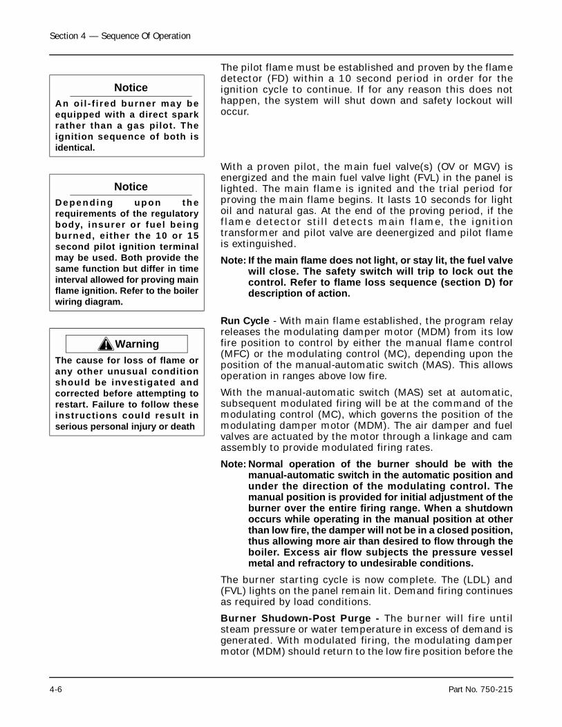
Section 4 — Sequence Of Operation
4-6 Part No. 750-215
The pilot flame must be established and proven by the flamedetector (FD) within a 10 second period in order for theignition cycle to continue. If for any reason this does nothappen, the system will shut down and safety lockout willoccur.
With a proven pilot, the main fuel valve(s) (OV or MGV) isenergized and the main fuel valve light (FVL) in the panel islighted. The main flame is ignited and the trial period forproving the main flame begins. It lasts 10 seconds for lightoil and natural gas. At the end of the proving period, if theflame detector still detects main flame, the ignitiontransformer and pilot valve are deenergized and pilot flameis extinguished.
Note: If the main flame does not light, or stay lit, the fuel valvewill close. The safety switch will trip to lock out thecontrol. Refer to flame loss sequence (section D) fordescription of action.
Run Cycle - With main flame established, the program relayreleases the modulating damper motor (MDM) from its lowfire position to control by either the manual flame control(MFC) or the modulating control (MC), depending upon theposition of the manual-automatic switch (MAS). This allowsoperation in ranges above low fire.
With the manual-automatic switch (MAS) set at automatic,subsequent modulated firing will be at the command of themodulating control (MC), which governs the position of themodulating damper motor (MDM). The air damper and fuelvalves are actuated by the motor through a linkage and camassembly to provide modulated firing rates.
Note: Normal operation of the burner should be with themanual-automatic switch in the automatic position andunder the direction of the modulating control. Themanual position is provided for initial adjustment of theburner over the entire firing range. When a shutdownoccurs while operating in the manual position at otherthan low fire, the damper will not be in a closed position,thus allowing more air than desired to flow through theboiler. Excess air flow subjects the pressure vesselmetal and refractory to undesirable conditions.
The burner starting cycle is now complete. The (LDL) and(FVL) lights on the panel remain lit. Demand firing continuesas required by load conditions.
Burner Shudown-Post Purge - The burner will fire untilsteam pressure or water temperature in excess of demand isgenerated. With modulated firing, the modulating dampermotor (MDM) should return to the low fire position before the
NoticeAn oi l - f i red burner may beequipped with a direct sparkrather than a gas pilot. Theignition sequence of both isidentical.
NoticeDe pe n d i ng up on th erequirements of the regulatorybody, insurer or fuel beingburned, ei ther the 10 or 15second pilot ignition terminalmay be used. Both provide thesame function but differ in timeinterval allowed for proving mainflame ignition. Refer to the boilerwiring diagram.
! WarningThe cause for loss of flame orany other unusual conditionshould be investigated andcorrected before attempting torestart. Failure to follow theseinstructions could result inserious personal injury or death
Section 4 — Sequence Of Operation
Part No. 750-215 4-7
operating limit control (OLC) opens. When the limit controlcircuit is opened, the following sequence occurs:
The main fuel valve circuit is deenergized, causing the mainfuel valve (MGV) or (OV) to close. The flame is extinguished.The control panel lights (LDL) and (FVL) are turned off. Theblower motor continues to run to force air through the boilerfor the post purge period.
The blower motor start circuit is deenergized at the end ofthe post purge cycle and the shutdown cycle is complete.
The program relay is now ready for subsequent recycling,and when steam pressure or water temperature drops toclose the contacts of the operating control, the burner againgoes through its normal starting and operating cycle.
D.FLAME LOSS SEQUENCEThe program relay will recycle automatically each time theoperating control closes, or after a power failure. It willlockout following a safety shutdown caused by failure toignite the pilot, or the main flame, or by loss of flame.Lockout will also occur if flame or flame simulating conditionoccurs during the prepurge period.
The control will prevent start-up or ignition if limit circuitcontrols or fuel valve interlocks are open. The control willlock out upon any abnormal condition affecting airsupervisory controls wired in the running interlock circuit.
1. No pilot flame.
The pilot flame must be ignited and proven within a 10-second period after the ignition cycle begins. If not provenwithin this period, the main fuel valve circuit will not bepowered and the fuel valve(s) will not be energized. Theignition circuit is immediately deenergized and the pilotvalve closes, the reset switch lights and lockout occursimmediately.
The blower motor will continue to operate. The flame failurelight and the alarm bell (optional) are energized 10 secondslater.
The blower motor will be deenergized. The lockout switchmust be manually reset before operation can be resumed.(Refer to the previous caution.)
2. Pilot but no main flame.
When the pilot flame is proven, the main fuel valve circuit isenergized. Depending upon the length of the trial-for-ignitionperiod, the pilot flame will be extinguished 10 or 15 secondslater. The flame detecting circuit will respond to deenergizethe main fuel valve circuit within 2 to 4 seconds to stop theflow of fuel. The reset switch lights and lockout occursimmediately. The blower motor will continue to operate.
! CautionThe lockout switch must bemanually reset following a safetyshutdown. The cause for loss offlame or any unusual conditionshould be invest igated andcorrected before attempting torestart. Failure to follow theseinstructions could cause damageto the equipment.
Section 4 — Sequence Of Operation
4-8 Part No. 750-215
The flame failure light and alarm bell (optional) areenergized 10 seconds later.
The blower motor will be then deenergized. The lockoutswitch must be manually reset before operation can beresumed. (Refer to the previous caution.)
3. Loss of flame.
If a flame outage occurs during normal operation and/or theflame is no longer sensed by the detector, the flame relay willtrip within 2 to 4 seconds to deenergize the fuel valve circuitand shut off the fuel flow. The reset switch lights and lockoutoccurs immediately. The blower motor continues operation.The flame failure light and alarm bell (optional) areenergized 10 seconds later.
The blower motor will be deenergized. The lockout switchmust be manually reset before operation can be resumed.(Refer to the previous caution.)
If the burner will not start, or upon a safety lockout, thetrouble shooting section in the operating manual and thetechnical bulletin should be referred to for assistance inpinpointing problems that may not be readily apparent.
The program relay has the capability to self-diagnose and todisplay a code or message that indicates the failurecondition. Refer to the control bulletin for specifics andsuggested remedies. Familiarity with the program relay andother controls in the system can be obtained by studying thecontents of the manual and this bulletin.
Knowledge of the system and its controls will maketroubleshooting much easier. Costly down time or delays canbe prevented by systematic checks of the actual operationagainst the normal sequence to determine the stage atwhich performance deviates from normal. Following aroutine may possibly eliminate overlooking an obviouscondition, often one that is relatively simple to correct.
Remember, a safety device, for the most part, is doing its jobwhen it shuts down or refuses to operate. Never attempt tocircumvent any of the safety features.
Preventive maintenance and scheduled inspection of allcomponents should be followed. Periodic checking of therelay is recommended to see that a safety lockout will occurunder conditions of failure to ignite either pilot or mainflame, or from loss of flame.
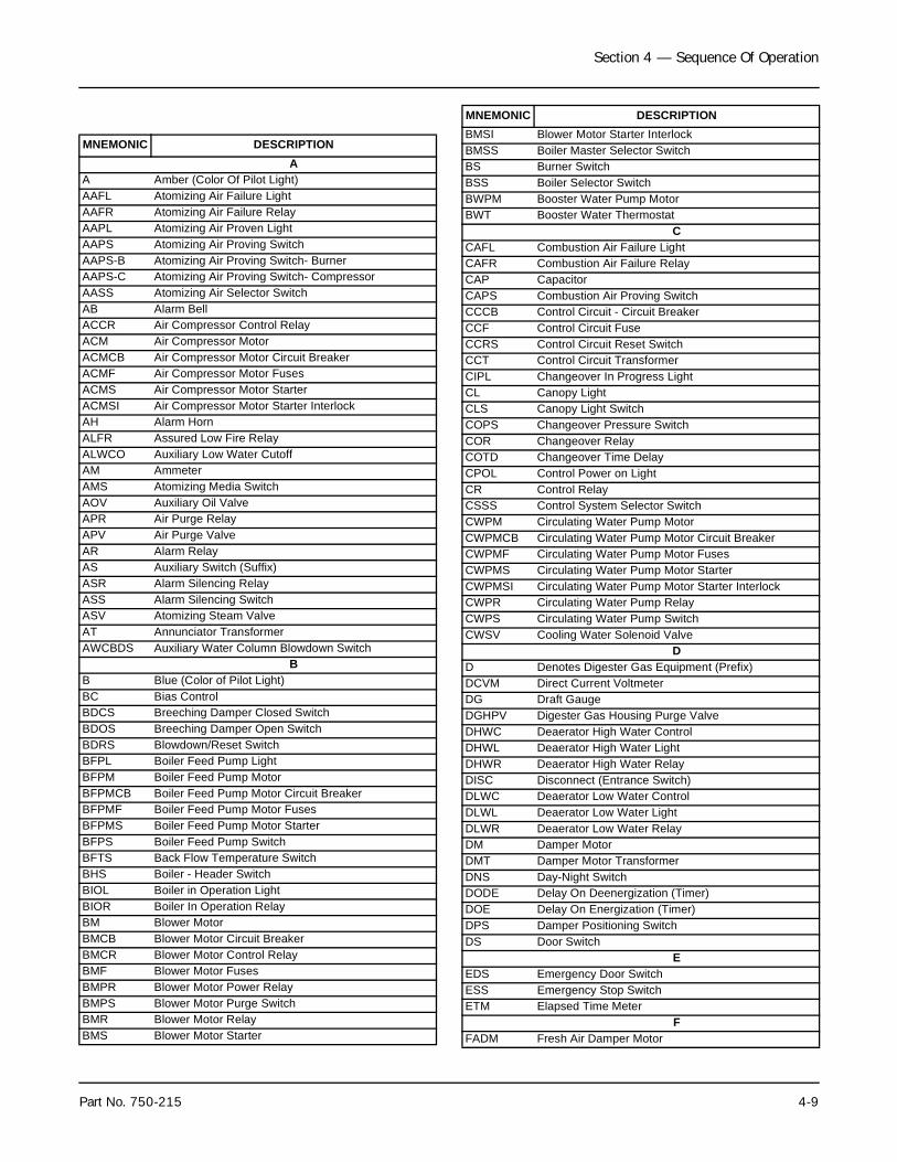
Section 4 — Sequence Of Operation
Part No. 750-215 4-9
MNEMONIC DESCRIPTIONA
A Amber (Color Of Pilot Light)AAFL Atomizing Air Failure LightAAFR Atomizing Air Failure RelayAAPL Atomizing Air Proven LightAAPS Atomizing Air Proving SwitchAAPS-B Atomizing Air Proving Switch- BurnerAAPS-C Atomizing Air Proving Switch- CompressorAASS Atomizing Air Selector SwitchAB Alarm BellACCR Air Compressor Control RelayACM Air Compressor MotorACMCB Air Compressor Motor Circuit BreakerACMF Air Compressor Motor FusesACMS Air Compressor Motor StarterACMSI Air Compressor Motor Starter InterlockAH Alarm HornALFR Assured Low Fire RelayALWCO Auxiliary Low Water CutoffAM AmmeterAMS Atomizing Media SwitchAOV Auxiliary Oil ValveAPR Air Purge RelayAPV Air Purge ValveAR Alarm RelayAS Auxiliary Switch (Suffix)ASR Alarm Silencing RelayASS Alarm Silencing SwitchASV Atomizing Steam ValveAT Annunciator TransformerAWCBDS Auxiliary Water Column Blowdown Switch
BB Blue (Color of Pilot Light)BC Bias ControlBDCS Breeching Damper Closed SwitchBDOS Breeching Damper Open SwitchBDRS Blowdown/Reset SwitchBFPL Boiler Feed Pump LightBFPM Boiler Feed Pump MotorBFPMCB Boiler Feed Pump Motor Circuit BreakerBFPMF Boiler Feed Pump Motor FusesBFPMS Boiler Feed Pump Motor StarterBFPS Boiler Feed Pump SwitchBFTS Back Flow Temperature SwitchBHS Boiler - Header SwitchBIOL Boiler in Operation LightBIOR Boiler In Operation RelayBM Blower MotorBMCB Blower Motor Circuit BreakerBMCR Blower Motor Control RelayBMF Blower Motor FusesBMPR Blower Motor Power RelayBMPS Blower Motor Purge SwitchBMR Blower Motor RelayBMS Blower Motor Starter
BMSI Blower Motor Starter Interlock BMSS Boiler Master Selector SwitchBS Burner SwitchBSS Boiler Selector SwitchBWPM Booster Water Pump MotorBWT Booster Water Thermostat
CCAFL Combustion Air Failure LightCAFR Combustion Air Failure RelayCAP CapacitorCAPS Combustion Air Proving SwitchCCCB Control Circuit - Circuit BreakerCCF Control Circuit FuseCCRS Control Circuit Reset SwitchCCT Control Circuit TransformerCIPL Changeover In Progress LightCL Canopy LightCLS Canopy Light SwitchCOPS Changeover Pressure SwitchCOR Changeover RelayCOTD Changeover Time DelayCPOL Control Power on LightCR Control RelayCSSS Control System Selector SwitchCWPM Circulating Water Pump MotorCWPMCB Circulating Water Pump Motor Circuit BreakerCWPMF Circulating Water Pump Motor FusesCWPMS Circulating Water Pump Motor StarterCWPMSI Circulating Water Pump Motor Starter InterlockCWPR Circulating Water Pump RelayCWPS Circulating Water Pump SwitchCWSV Cooling Water Solenoid Valve
DD Denotes Digester Gas Equipment (Prefix)DCVM Direct Current VoltmeterDG Draft GaugeDGHPV Digester Gas Housing Purge ValveDHWC Deaerator High Water ControlDHWL Deaerator High Water LightDHWR Deaerator High Water RelayDISC Disconnect (Entrance Switch)DLWC Deaerator Low Water ControlDLWL Deaerator Low Water LightDLWR Deaerator Low Water RelayDM Damper MotorDMT Damper Motor TransformerDNS Day-Night SwitchDODE Delay On Deenergization (Timer)DOE Delay On Energization (Timer)DPS Damper Positioning SwitchDS Door Switch
EEDS Emergency Door SwitchESS Emergency Stop SwitchETM Elapsed Time Meter
FFADM Fresh Air Damper Motor
MNEMONIC DESCRIPTION
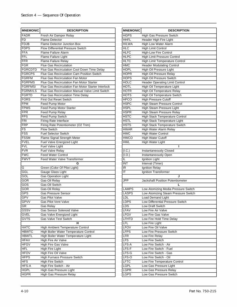
Section 4 — Sequence Of Operation
4-10 Part No. 750-215
FADR Fresh Air Damper RelayFD Flame DetectorFDJB Flame Detector Junction BoxFDPS Flow Differential Pressure SwitchFFA Flame Failure AlarmFFL Flame Failure LightFFR Flame Failure RelayFGR Flue Gas RecirculationFGRCDTD Flue Gas Recirculation Cool Down Time DelayFGRCPS Flue Gas Recirculation Cam Position SwitchFGRFM Flue Gas Recirculation Fan MotorFGRFMS Flue Gas Recirculation Fan Motor StarterFGRFMSI Flue Gas Recirculation Fan Motor Starter InterlockFGRMVLS Flue Gas Recirculation Manual Valve Limit SwitchFGRTD Flue Gas Recirculation Time DelayFORS First Out Reset SwitchFPM Feed Pump MotorFPMS Feed Pump Motor StarterFPR Feed Pump RelayFPS Feed Pump SwitchFRI Firing Rate InterfaceFRP Firing Rate Potentiometer (O2 Trim)FS Flow SwitchFSS Fuel Selector SwitchFSSM Flame Signal Strength MeterFVEL Fuel Valve Energized LightFVL Fuel Valve LightFVR Fuel Valve RelayFWC Feed Water ControlFWVT Feed Water Valve Transformer
GG Green (Color Of Pilot Light)GGL Gauge Glass LightGOL Gas Operation LightGOR Gas-Oil RelayGOS Gas-Oil SwitchGOR Gas-Oil RelayGPS Gas Pressure SensorGPV Gas Pilot ValveGPVV Gas Pilot Vent ValveGR Gas RelayGSSV Gas Sensor Solenoid ValveGVEL Gas Valve Energized LightGVTS Gas Valve Test Switch
HHATC High Ambient Temperature ControlHBWTC High Boiler Water Temperature ControlHBWTL High Boiler Water Temperature LightHFAV High Fire Air ValveHFGV High Fire Gas ValveHFL High Fire LightHFOV High Fire Oil ValveHFPS High Furnace Pressure SwitchHFS High Fire SwitchHFS-A High Fire Switch - AirHGPL High Gas Pressure LightHGPR High Gas Pressure Relay
MNEMONIC DESCRIPTIONHGPS High Gas Pressure SwitchHHFL Header High Fire LightH/LWA High Low Water AlarmHLC High Limit ControlHLFC High-Low Fire ControlHLPC High Limit Pressure ControlHLTC High Limit Temperature ControlHMC Header Modulating ControlHOPL High Oil Pressure LightHOPR High Oil Pressure RelayHOPS High Oil Pressure SwitchHOLC Header Operating Limit ControlHOTL High Oil Temperature LightHOTR High Oil Temperature RelayHOTS High Oil Temperature SwitchHPCO High Pressure CutoffHSPC High Steam Pressure ControlHSPL High Steam Pressure LightHSPR High Steam Pressure RelayHSTC High Stack Temperature ControlHSTL High Stack Temperature LightHSTS High Stack Temperature SwitchHWAR High Water Alarm RelayHWC High Water ControlHWCO High Water CutoffHWL High Water Light
I(I.C.) Instantaneously Closed(I.O.) Instantaneously OpenIL Ignition LightINT Interval (Timer)IR Ignition RelayIT Ignition Transformer
JJPP Jackshaft Position Potentiometer
LLAMPS Low Atomizing Media Pressure SwitchLASPS Low Atomizing Steam Pressure SwitchLDL Load Demand LightLDPS Low Differential Pressure SwitchLDS Low Draft SwitchLFAV Low Fire Air ValveLFGV Low Fire Gas ValveLFHTD Low Fire Hold Time DelayLFL Low Fire LightLFOV Low Fire Oil ValveLFPS Low Fire Pressure SwitchLFR Low Fire RelayLFS Low Fire SwitchLFS-A Low Fire Switch - AirLFS-F Low Fire Switch - FuelLFS-G Low Fire Switch - GasLFS-O Low Fire Switch - OilLFTC Low Fire Temperature ControlLGPL Low Gas Pressure LightLGPR Low Gas Pressure RelayLGPS Low Gas Pressure Switch
MNEMONIC DESCRIPTION
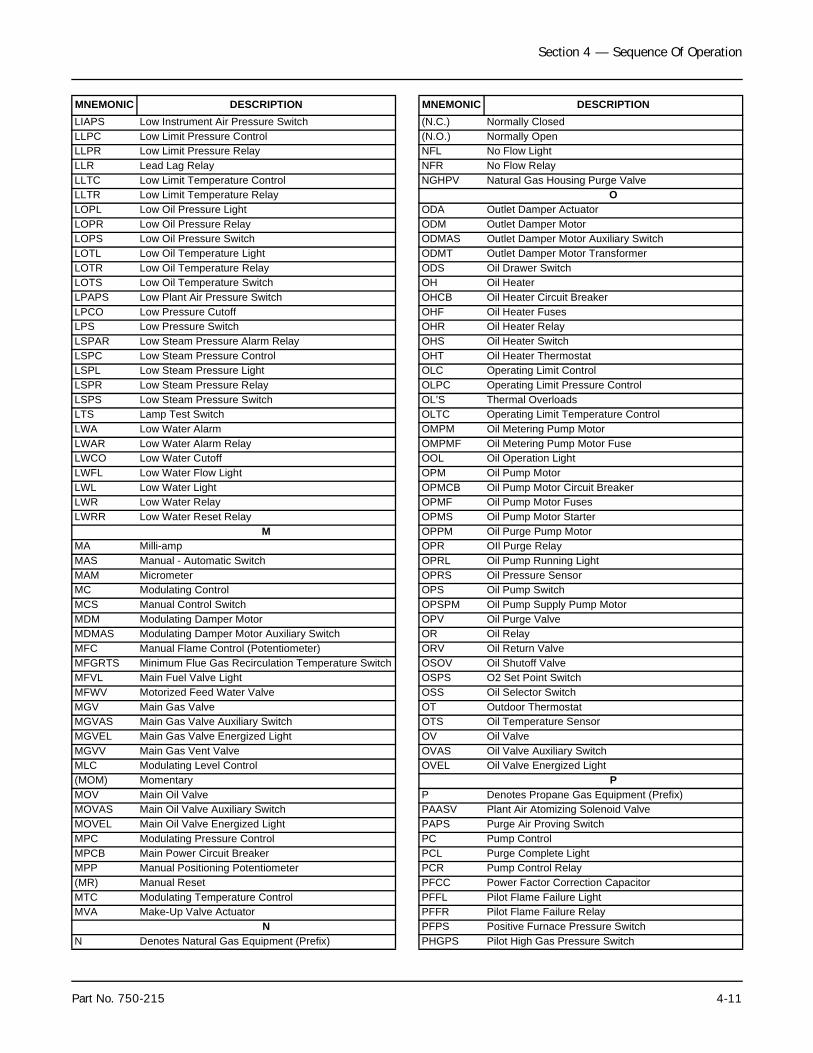
Section 4 — Sequence Of Operation
Part No. 750-215 4-11
LIAPS Low Instrument Air Pressure SwitchLLPC Low Limit Pressure ControlLLPR Low Limit Pressure RelayLLR Lead Lag RelayLLTC Low Limit Temperature ControlLLTR Low Limit Temperature RelayLOPL Low Oil Pressure LightLOPR Low Oil Pressure RelayLOPS Low Oil Pressure SwitchLOTL Low Oil Temperature LightLOTR Low Oil Temperature RelayLOTS Low Oil Temperature SwitchLPAPS Low Plant Air Pressure SwitchLPCO Low Pressure CutoffLPS Low Pressure SwitchLSPAR Low Steam Pressure Alarm RelayLSPC Low Steam Pressure ControlLSPL Low Steam Pressure LightLSPR Low Steam Pressure RelayLSPS Low Steam Pressure SwitchLTS Lamp Test SwitchLWA Low Water AlarmLWAR Low Water Alarm RelayLWCO Low Water CutoffLWFL Low Water Flow LightLWL Low Water LightLWR Low Water RelayLWRR Low Water Reset Relay
MMA Milli-ampMAS Manual - Automatic SwitchMAM MicrometerMC Modulating ControlMCS Manual Control SwitchMDM Modulating Damper MotorMDMAS Modulating Damper Motor Auxiliary SwitchMFC Manual Flame Control (Potentiometer)MFGRTS Minimum Flue Gas Recirculation Temperature SwitchMFVL Main Fuel Valve LightMFWV Motorized Feed Water ValveMGV Main Gas ValveMGVAS Main Gas Valve Auxiliary SwitchMGVEL Main Gas Valve Energized LightMGVV Main Gas Vent ValveMLC Modulating Level Control(MOM) MomentaryMOV Main Oil ValveMOVAS Main Oil Valve Auxiliary SwitchMOVEL Main Oil Valve Energized LightMPC Modulating Pressure ControlMPCB Main Power Circuit BreakerMPP Manual Positioning Potentiometer(MR) Manual ResetMTC Modulating Temperature ControlMVA Make-Up Valve Actuator
NN Denotes Natural Gas Equipment (Prefix)
MNEMONIC DESCRIPTION(N.C.) Normally Closed(N.O.) Normally OpenNFL No Flow LightNFR No Flow RelayNGHPV Natural Gas Housing Purge Valve
OODA Outlet Damper ActuatorODM Outlet Damper MotorODMAS Outlet Damper Motor Auxiliary SwitchODMT Outlet Damper Motor TransformerODS Oil Drawer SwitchOH Oil HeaterOHCB Oil Heater Circuit BreakerOHF Oil Heater FusesOHR Oil Heater RelayOHS Oil Heater SwitchOHT Oil Heater ThermostatOLC Operating Limit ControlOLPC Operating Limit Pressure ControlOL’S Thermal OverloadsOLTC Operating Limit Temperature ControlOMPM Oil Metering Pump MotorOMPMF Oil Metering Pump Motor FuseOOL Oil Operation LightOPM Oil Pump MotorOPMCB Oil Pump Motor Circuit BreakerOPMF Oil Pump Motor FusesOPMS Oil Pump Motor StarterOPPM Oil Purge Pump MotorOPR OIl Purge RelayOPRL Oil Pump Running LightOPRS Oil Pressure SensorOPS Oil Pump SwitchOPSPM Oil Pump Supply Pump MotorOPV Oil Purge ValveOR Oil RelayORV Oil Return ValveOSOV Oil Shutoff ValveOSPS O2 Set Point SwitchOSS Oil Selector SwitchOT Outdoor ThermostatOTS Oil Temperature SensorOV Oil ValveOVAS Oil Valve Auxiliary SwitchOVEL Oil Valve Energized Light
PP Denotes Propane Gas Equipment (Prefix)PAASV Plant Air Atomizing Solenoid ValvePAPS Purge Air Proving SwitchPC Pump ControlPCL Purge Complete LightPCR Pump Control RelayPFCC Power Factor Correction CapacitorPFFL Pilot Flame Failure LightPFFR Pilot Flame Failure RelayPFPS Positive Furnace Pressure SwitchPHGPS Pilot High Gas Pressure Switch
MNEMONIC DESCRIPTION
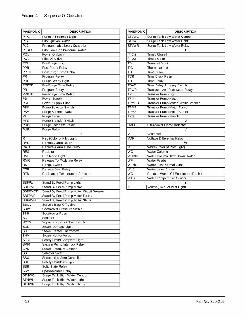
Section 4 — Sequence Of Operation
4-12 Part No. 750-215
PIPL Purge in Progress LightPIS Pilot Ignition SwitchPLC Programmable Logic ControllerPLGPS Pilot Low Gas Pressure SwitchPOL Power On LightPOV Pilot Oil ValvePPL Pre-Purging LightPPR Post Purge RelayPPTD Post Purge Time DelayPR Program RelayPRL Purge Ready LightPRPTD Pre-Purge Time DelayPR Program RelayPRPTD Per-Purge Time DelayPS Power SupplyPSF Power Supply FusePSS Pump Selector SwitchPSV Purge Solenoid ValvePT Purge TimerPTS Pump Transfer SwitchPUCR Purge Complete RelayPUR Purge Relay
RR Red (Color of Pilot Light)RAR Remote Alarm RelayRATD Remote Alarm Time DelayRES ResistorRML Run Mode LightRMR Release To Modulate RelayRS Range SwitchRSR Remote Start RelayRTD Resistance Temperature Detector
SSBFPL Stand By Feed Pump LightSBFPM Stand By Feed Pump MotorSBFPMCB Stand By Feed Pump Motor Circuit BreakerSBFPMF Stand By Feed Pump Motor FusesSBFPMS Stand By Feed Pump Motor StarterSBOV Surface Blow Off ValveSBPS Sootblower Pressure SwitchSBR Sootblower RelaySC ScannerSCTS Supervisory Cock Test SwitchSDL Steam Demand LightSHT Steam Heater ThermostatSHV Steam Heater ValveSLCL Safety Limits Complete LightSPIR System Pump Interlock RelaySPS Steam Pressure SensorSS Selector SwitchSSC Sequencing Step ControllerSSL Safety Shutdown LightSSR Solid State RelaySSV SpanSolenoid RelaySTHWC Surge Tank High Water ControlSTHWL Surge Tank High Water LightSTHWR Surge Tank High Water Relay
MNEMONIC DESCRIPTIONSTLWC Surge Tank Low Water ControlSTLWL Surge Tank Low Water LightSTLWR Surge Tank Low Water Relay
T(T.C.) Timed Closed(T.O.) Timed OpenTB Terminal BlockT/C ThermocoupleTC Time ClockTCR Time Clock RelayTD Time DelayTDAS Time Delay Auxiliary SwitchTFWR Transistorized Feedwater RelayTPL Transfer Pump LightTPM Transfer Pump MotorTPMCB Transfer Pump Motor Circuit BreakerTPMF Transfer Pump Motor FusesTPMS Transfer Pump Motor StarterTPS Transfer Pump Switch
UUVFD Ultra-Violet Flame Detector
VV VoltmeterVDR Voltage Differential Relay
WW White (Color of Pilot Light)WC Water ColumnWCBDS Water Column Blow Down SwitchWF Water FeederWFNL Water Flow Normal LightWLC Water Level ControlWO Denotes Waste Oil Equipment (Prefix)WTS Water Temperature Sensor
YY Yellow (Color of Pilot Light)
MNEMONIC DESCRIPTION
Milwaukee, Wisconsin
www.cleaver-brooks.com
Section 5Starting and Operating InstructionsA. General Preparation for Initial Startup . . . . . . . . . . . . . . . . . . . . . . 5-2B. Startup Procedures . . . . . . . . . . . . . . . . . . . . . . . . . . . . . . . . . . . 5-6C. Burner Adjustments, Single Fuel Natural Gas . . . . . . . . . . . . . . . . . 5-8D. Burner Adjustments, Single Fuel, Oil-fired
(Return Flow Pressure Atomization) . . . . . . . . . . . . . . . . . . . . . . . 5-12E. Burner Adjustments, Combination Gas and Oil . . . . . . . . . . . . . . . 5-14F. Startup, Operating And Shutdown - All Fuels . . . . . . . . . . . . . . . . . 5-19
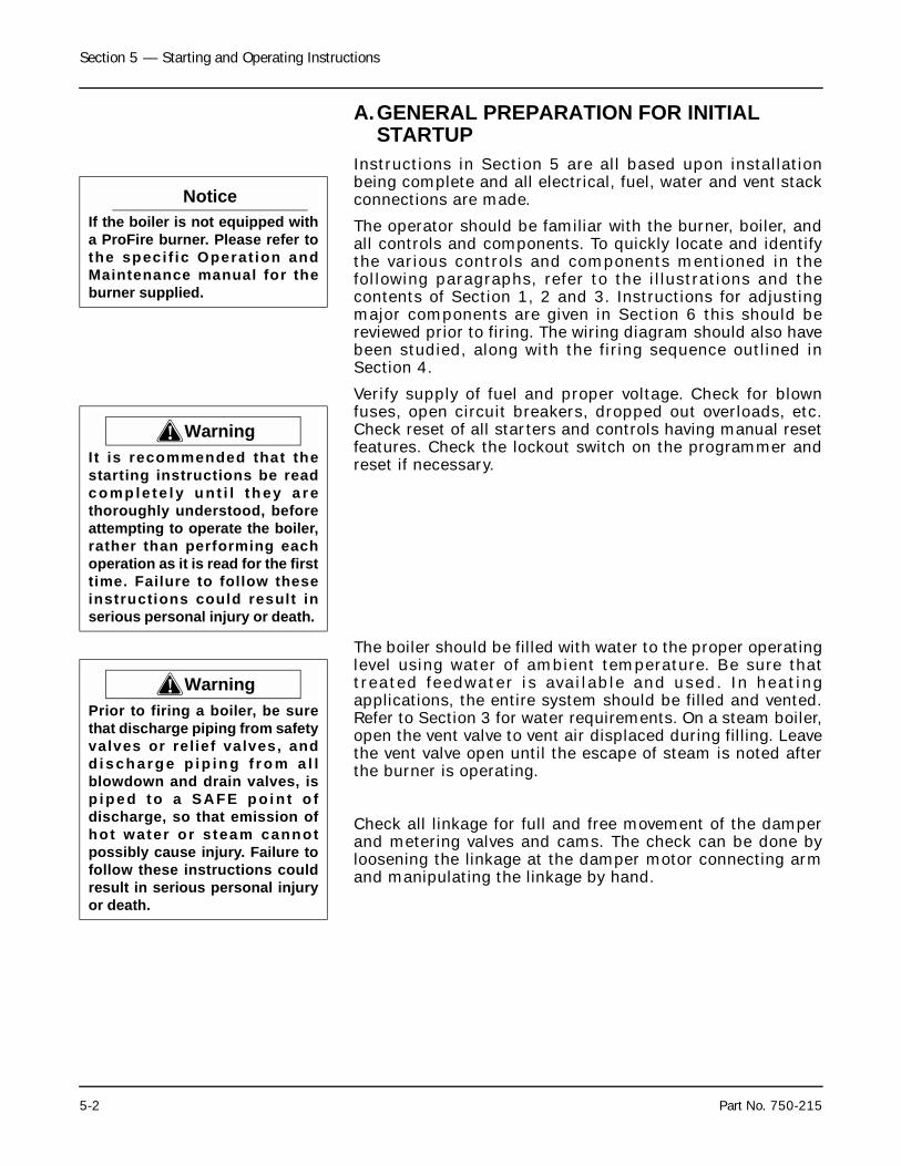
Section 5 — Starting and Operating Instructions
5-2 Part No. 750-215
A.GENERAL PREPARATION FOR INITIAL STARTUP
Instructions in Section 5 are all based upon installationbeing complete and all electrical, fuel, water and vent stackconnections are made.
The operator should be familiar with the burner, boiler, andall controls and components. To quickly locate and identifythe various controls and components mentioned in thefollowing paragraphs, refer to the illustrations and thecontents of Section 1, 2 and 3. Instructions for adjustingmajor components are given in Section 6 this should bereviewed prior to firing. The wiring diagram should also havebeen studied, along with the firing sequence outlined inSection 4.
Verify supply of fuel and proper voltage. Check for blownfuses, open circuit breakers, dropped out overloads, etc.Check reset of all starters and controls having manual resetfeatures. Check the lockout switch on the programmer andreset if necessary.
The boiler should be filled with water to the proper operatinglevel using water of ambient temperature. Be sure thattreated feedwater is available and used. In heatingapplications, the entire system should be filled and vented.Refer to Section 3 for water requirements. On a steam boiler,open the vent valve to vent air displaced during filling. Leavethe vent valve open until the escape of steam is noted afterthe burner is operating.
Check all linkage for full and free movement of the damperand metering valves and cams. The check can be done byloosening the linkage at the damper motor connecting armand manipulating the linkage by hand.
NoticeIf the boiler is not equipped witha ProFire burner. Please refer tothe speci f ic Operat ion andMaintenance manual for theburner supplied.
! WarningIt is recommended that thestarting instructions be readc omp le te l y u n t i l th ey a r ethoroughly understood, beforeattempting to operate the boiler,rather than performing eachoperation as it is read for the firsttime. Failure to follow theseinstructions could result inserious personal injury or death.
! WarningPrior to firing a boiler, be surethat discharge piping from safetyvalves or relief valves, andd i s ch ar g e p ip in g f r o m a l lblowdown and drain valves, isp i pe d to a SA FE p o i n t o fdischarge, so that emission ofhot water or s team cannotpossibly cause injury. Failure tofollow these instructions couldresult in serious personal injuryor death.
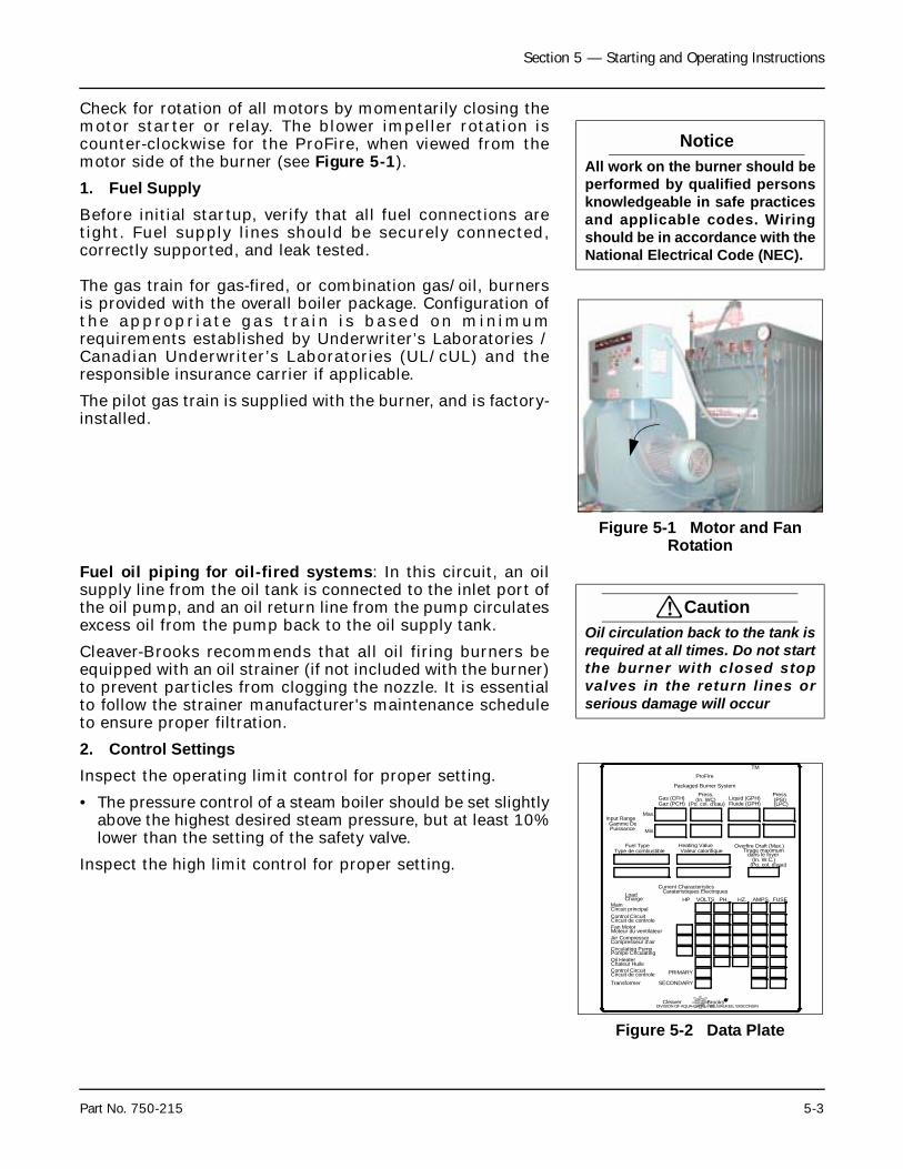
Section 5 — Starting and Operating Instructions
Part No. 750-215 5-3
Check for rotation of all motors by momentarily closing themotor starter or relay. The blower impeller rotation iscounter-clockwise for the ProFire, when viewed from themotor side of the burner (see Figure 5-1).
1. Fuel SupplyBefore initial startup, verify that all fuel connections aretight. Fuel supply lines should be securely connected,correctly supported, and leak tested.
The gas train for gas-fired, or combination gas/oil, burnersis provided with the overall boiler package. Configuration ofthe appropr ia te gas t ra in i s based on min imumrequirements established by Underwriter’s Laboratories /Canadian Underwriter’s Laboratories (UL/cUL) and theresponsible insurance carrier if applicable.
The pilot gas train is supplied with the burner, and is factory-installed.
Fuel oil piping for oil-fired systems: In this circuit, an oilsupply line from the oil tank is connected to the inlet port ofthe oil pump, and an oil return line from the pump circulatesexcess oil from the pump back to the oil supply tank.
Cleaver-Brooks recommends that all oil firing burners beequipped with an oil strainer (if not included with the burner)to prevent particles from clogging the nozzle. It is essentialto follow the strainer manufacturer's maintenance scheduleto ensure proper filtration.
2. Control Settings Inspect the operating limit control for proper setting.
• The pressure control of a steam boiler should be set slightlyabove the highest desired steam pressure, but at least 10%lower than the setting of the safety valve.
Inspect the high limit control for proper setting.
NoticeAll work on the burner should beperformed by qualified personsknowledgeable in safe practicesand applicable codes. Wiringshould be in accordance with theNational Electrical Code (NEC).
Figure 5-1 Motor and Fan Rotation
! CautionOil circulation back to the tank isrequired at all times. Do not startthe burner with closed stopvalves in the return lines orserious damage will occur
Figure 5-2 Data Plate
Packaged Burner System
Fan Motor
BrooksMILWAUKEE, WISCONSINDIVISION OF AQUA-CHEM, INC.
R
Air CompressorMoteur du ventilateur
Compresseur d'air
Cleaver
PH.Main
LoadHP VOLTS
Control Circuit
HZ. AMPS.
Current CharacteristicsCarateristiques Electriques
Charge
Circuit principal
Circuit de controle
(LPC)(PSI)Press.
Liquid (GPH)Fluide (GPH)
Gas (CFH)Gaz (PCH)
Min.
Max.
(Po. col. d'eau)
Press.(In. WC)
Type de combustibleFuel Type Heating Value
Valeur calorifique
Gamme DeInput Range
TMProFire
FUSE
Control CircuitCircuit de controleTransformer
PRIMARY
SECONDARY
(Po. col. d'eau)(In. W.C.)
Overfire Draft (Max.)dans le foyer
Tirage maximum
Puissance
Pompe CirculatingCirculating Pump
Chaleur HuileOil Heater
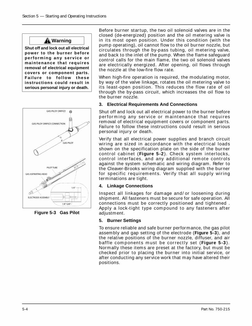
Section 5 — Starting and Operating Instructions
5-4 Part No. 750-215
Before burner startup, the two oil solenoid valves are in theclosed (de-energized) position and the oil metering valve isin its most open position. Under this condition (with thepump operating), oil cannot flow to the oil burner nozzle, butcirculates through the by-pass tubing, oil metering valve,and back to the inlet of the pump. When the flame safeguardcontrol calls for the main flame, the two oil solenoid valvesare electrically energized. After opening, oil flows throughthe nozzle at the low-fire flow rate.
When high-fire operation is required, the modulating motor,by way of the valve linkage, rotates the oil metering valve toits least-open position. This reduces the flow rate of oilthrough the by-pass circuit, which increases the oil flow tothe burner nozzle.
3. Electrical Requirements And ConnectionsShut off and lock out all electrical power to the burner beforeperforming any service or maintenance that requiresremoval of electrical equipment covers or component parts.Failure to follow these instructions could result in seriouspersonal injury or death.
Verify that all electrical power supplies and branch circuitwiring are sized in accordance with the electrical loadsshown on the specification plate on the side of the burnercontrol cabinet (Figure 5-2). Check system interlocks,control interfaces, and any additional remote controlsagainst the system schematic and wiring diagram. Refer tothe Cleaver-Brooks wiring diagram supplied with the burnerfor specific requirements. Verify that all supply wiringterminations are tight.
4. Linkage ConnectionsInspect all linkages for damage and/or loosening duringshipment. All fasteners must be secure for safe operation. Allconnections must be correctly positioned and tightened .Apply a lock-tight type compound to any fasteners afteradjustment.
5. Burner SettingsTo ensure reliable and safe burner performance, the gas pilotassembly and gap setting of the electrode (Figure 5-3), andthe relative positions of the burner nozzle, diffuser, and airbaffle components must be correctly set (Figure 5-3).Normally these items are preset at the factory, but must bechecked prior to placing the burner into initial service, orafter conducting any service work that may have altered theirpositions.
! WarningShut off and lock out all electricalpower to the burner beforepe r fo rming any ser v ice ormaintenance tha t requi resremoval of electrical equipmentcovers or component parts.Fa i lu re to fo l l ow t he s einstructions could result inserious personal injury or death.
Figure 5-3 Gas Pilot
ELECTRODE ASSEMBLY
PILOT TUBE
GAS ASPIRATING HEAD
1/4"
1/8" GAP
GAS PILOT
GAS PILOY ORIFICE
GAS PILOY ORIFICE CONNECTION
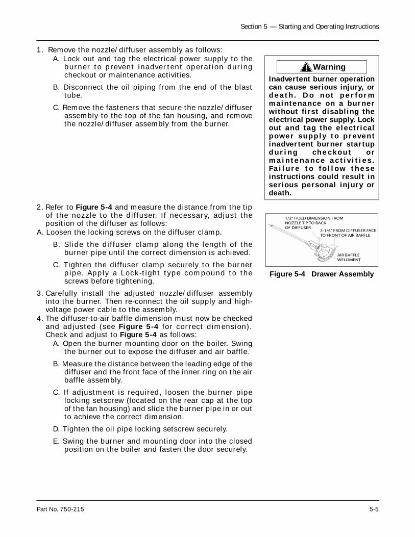
Section 5 — Starting and Operating Instructions
Part No. 750-215 5-5
1. Remove the nozzle/diffuser assembly as follows:A. Lock out and tag the electrical power supply to the
burner to prevent inadvertent operation duringcheckout or maintenance activities.
B. Disconnect the oil piping from the end of the blasttube.
C. Remove the fasteners that secure the nozzle/diffuserassembly to the top of the fan housing, and removethe nozzle/diffuser assembly from the burner.
2. Refer to Figure 5-4 and measure the distance from the tipof the nozzle to the diffuser. If necessary, adjust theposition of the diffuser as follows:
A. Loosen the locking screws on the diffuser clamp.
B. Slide the diffuser clamp along the length of theburner pipe until the correct dimension is achieved.
C. Tighten the diffuser clamp securely to the burnerpipe. Apply a Lock-tight type compound to thescrews before tightening.
3. Carefully install the adjusted nozzle/diffuser assemblyinto the burner. Then re-connect the oil supply and high-voltage power cable to the assembly.
4. The diffuser-to-air baffle dimension must now be checkedand adjusted (see Figure 5-4 for correct dimension).Check and adjust to Figure 5-4 as follows:
A. Open the burner mounting door on the boiler. Swingthe burner out to expose the diffuser and air baffle.
B. Measure the distance between the leading edge of thediffuser and the front face of the inner ring on the airbaffle assembly.
C. If adjustment is required, loosen the burner pipelocking setscrew (located on the rear cap at the topof the fan housing) and slide the burner pipe in or outto achieve the correct dimension.
D. Tighten the oil pipe locking setscrew securely.
E. Swing the burner and mounting door into the closedposition on the boiler and fasten the door securely.
! WarningInadvertent burner operationcan cause serious injury, ordeath . Do no t per fo rmmaintenance on a burnerwithout first disabling theelectrical power supply. Lockout and tag the electricalpower supply to preventinadvertent burner startupdur ing checkout o rmaintenance ac t iv i t i es .Fa i lu re to fo l low theseinstructions could result inserious personal injury ordeath.
Figure 5-4 Drawer Assembly
1/2" HOLD DIMENSION FROMNOZZLE TIP TO BACKOF DIFFUSER
3-1/4" FROM DIFFUSER FACETO FRONT OF AIR BAFFLE
AIR BAFFLEWELDMENT
Section 5 — Starting and Operating Instructions
5-6 Part No. 750-215
B.STARTUP PROCEDURESPRESTART TASKS AND CHECKLIST - ALL FUELS
Before proceeding with system startup and adjustment, besure that overall installation is complete. Review the boileroperating and installation manual set carefully to verify thatthe boiler is properly set up for operation. Check that allshipped-loose items (those items not installed whenshipped) have been correctly installed. Verify the supply offuel. Check to make sure the burner is wired as shown on thewiring diagram. Ensure that all control wiring terminals aretight.
Complete the following checklist in preparation for systemstartup:
• Confirm that the fuel and electrical connections have beencompleted in accordance with the applicable codes andinsurance requirements ( i f necessary), and thatconnections comply with the piping schematic and wiringdiagram.
• Check the combustion air fan motor for correct rotationaldirection.
• Check that the boiler is filled with water to the proper level,and that all circulating pumps (hot water units) arecorrectly installed and operational.
• Verify that there is proper gas pressure at the gas train, ifthis is a gas or combination burner. See the burnerspecification plate (Figure 5-8) for minimum and maximumnatural gas pressure requirements.
• For oil burners confirm that the oil tank is adequately filledwith the correct grade of fuel oil, and that any isolationvalves in the supply and return lines are open.
• Check that the flame safeguard has been properly installedinside the control panel.
• Provide the following test equipment on site:
1. Combustion analyzer for O2.2. U-tube manometer, or pressure gauge, to measure gas
pressures (main and pilot).3. Inclined manometer to measure draft pressures.4. Smoke spot tester for oil fired units. CO analyzer for gas
fired burners.5. Voltmeter.6. Thermometers and thermocouples.
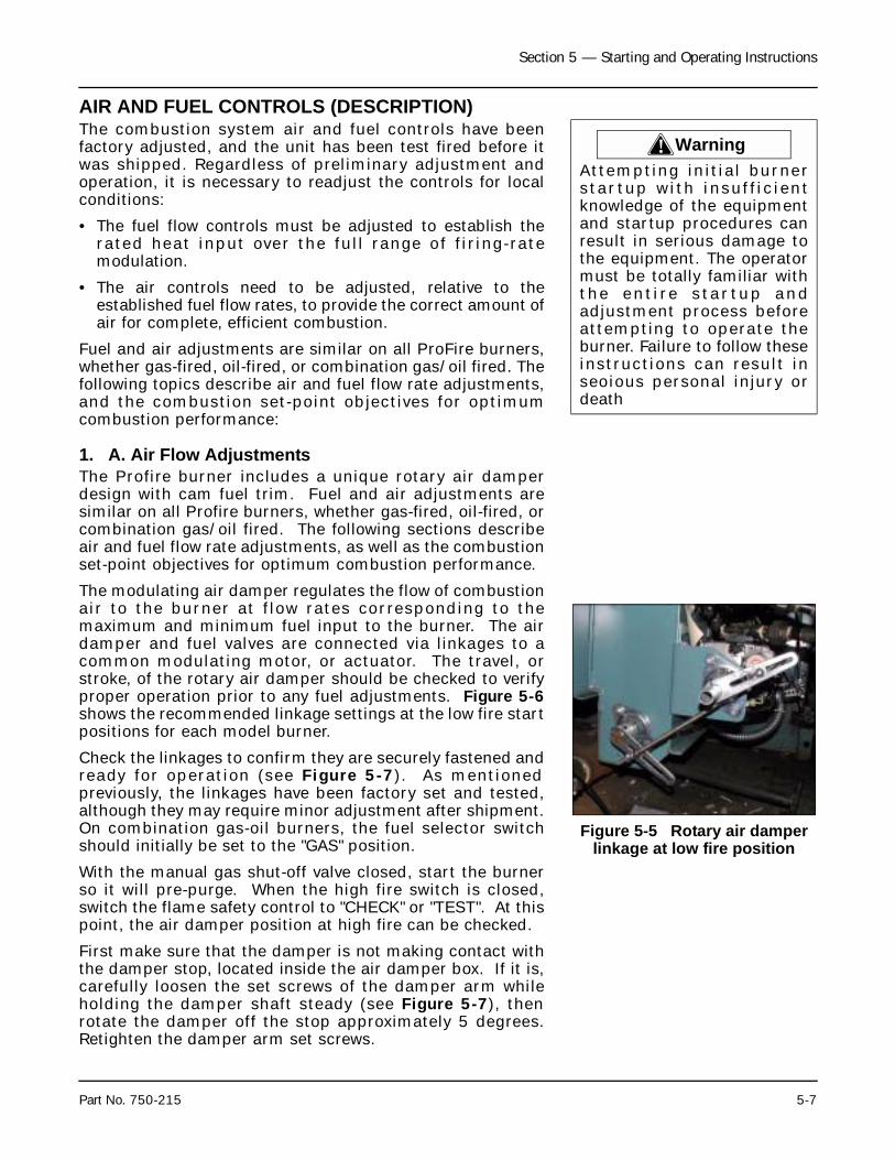
Section 5 — Starting and Operating Instructions
Part No. 750-215 5-7
AIR AND FUEL CONTROLS (DESCRIPTION)The combustion system air and fuel controls have beenfactory adjusted, and the unit has been test fired before itwas shipped. Regardless of preliminary adjustment andoperation, it is necessary to readjust the controls for localconditions:
• The fuel flow controls must be adjusted to establish therated heat input over the full range of f iring-ratemodulation.
• The air controls need to be adjusted, relative to theestablished fuel flow rates, to provide the correct amount ofair for complete, efficient combustion.
Fuel and air adjustments are similar on all ProFire burners,whether gas-fired, oil-fired, or combination gas/oil fired. Thefollowing topics describe air and fuel flow rate adjustments,and the combustion set-point objectives for optimumcombustion performance:
1. A. Air Flow AdjustmentsThe Profire burner includes a unique rotary air damperdesign with cam fuel trim. Fuel and air adjustments aresimilar on all Profire burners, whether gas-fired, oil-fired, orcombination gas/oil fired. The following sections describeair and fuel flow rate adjustments, as well as the combustionset-point objectives for optimum combustion performance.
The modulating air damper regulates the flow of combustionair to the burner at f low rates corresponding to themaximum and minimum fuel input to the burner. The airdamper and fuel valves are connected via linkages to acommon modulating motor, or actuator. The travel, orstroke, of the rotary air damper should be checked to verifyproper operation prior to any fuel adjustments. Figure 5-6shows the recommended linkage settings at the low fire startpositions for each model burner.
Check the linkages to confirm they are securely fastened andready for operation (see Figure 5-7). As mentionedpreviously, the linkages have been factory set and tested,although they may require minor adjustment after shipment.On combination gas-oil burners, the fuel selector switchshould initially be set to the "GAS" position.
With the manual gas shut-off valve closed, start the burnerso it will pre-purge. When the high fire switch is closed,switch the flame safety control to "CHECK" or "TEST". At thispoint, the air damper position at high fire can be checked.
First make sure that the damper is not making contact withthe damper stop, located inside the air damper box. If it is,carefully loosen the set screws of the damper arm whileholding the damper shaft steady (see Figure 5-7), thenrotate the damper off the stop approximately 5 degrees.Retighten the damper arm set screws.
! WarningAttempting initial burnerstar tup with insuf f ic ientknowledge of the equipmentand startup procedures canresult in serious damage tothe equipment. The operatormust be totally familiar withthe en t i re s ta r tup andadjustment process beforeattempting to operate theburner. Failure to follow theseinstructions can result inseoious personal injury ordeath
Figure 5-5 Rotary air damper linkage at low fire position
Section 5 — Starting and Operating Instructions
5-8 Part No. 750-215
The damper shaft slot should be in a near vertical position.The air damper can now be stroked for full modulation.Switch the f lame safety control back to "RUN". Themodulating motor should drive to the low fire position.Observe the air damper travel and adjust the linkage rodclamp if the air damper does not travel to the desiredposition (5 to 25 degrees open) at low fire -- depending onthe burner model, fuel, and turndown -- to a full openposition at high fire. If necessary, repeat untill air damperstrokes properely.
2. Combustion SettingsFuel and air flow rates are individually adjusted at low fire, athigh fire, and at each intermediate cam screw position toachieve rated heat input, firing rate turndown, optimumefficiency, safe operation, and the ability to cope withenvironmental changes (including air temperature, humidity,barometr ic pressure, ) and fuel proper ty changes.Adjustments may be required to meet certain environmentalemissions criteria, such as NOx or CO. Combustionadjustments also vary with specific system applications.
Turndown capability for oil is typically less than that fornatural gas. Therefore, on combination fueled burners, gasturndown performance may be restricted (or determined) bythe excess air levels set initially for oil combustion.
Two key components residing in flue gas are used tooptimize combustion efficiency; excess air and unburnedfuel. The system should be adjusted to the minimum excessair quantity that provides low levels of unburned fuel withsu f f ic ient remain ing oxygen to cope wi th normalatmospheric and fuel related changes. Unburned fuel ismeasured as carbon monoxide (CO) when burning naturalgas, and smoke spots when burning oil.
ProFire burners are capable of operating at CO levels of lessthan 50 ppm at all firing rates. The burner should be set-upand maintained to yield smoke spot levels less than a #2spot (ASTM D2156 Shell-Bacharach Scale) to minimize sootbuild-up in the boiler.
C.BURNER ADJUSTMENTS, SINGLE FUEL NATURAL GAS
Note: The operator must consider and allow for normalvariations in air and fuel, which would reduce the rangeof excessive oxygen in the flue gas accordingly.
NoticeThe low fire position will befine-tuned during combustionstart-up.
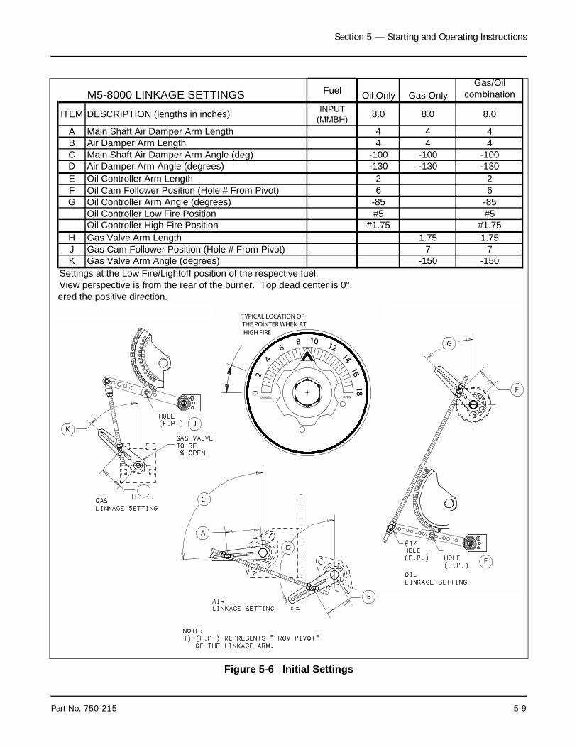
Section 5 — Starting and Operating Instructions
Part No. 750-215 5-9
Figure 5-6 Initial Settings
TYPICAL LOCATION OFTHE POINTER WHEN ATHIGH FIRE
OPENCLOSED
16
14
12108
6
42
0
18
KJ
H
A
C
D
B
G
E
F
M5-8000 LINKAGE SETTINGS Fuel Oil Only Gas OnlyGas/Oil
combination
ITEM DESCRIPTION (lengths in inches) INPUT (MMBH) 8.0 8.0 8.0
A Main Shaft Air Damper Arm Length 4 4 4B Air Damper Arm Length 4 4 4C Main Shaft Air Damper Arm Angle (deg) -100 -100 -100D Air Damper Arm Angle (degrees) -130 -130 -130E Oil Controller Arm Length 2 2F Oil Cam Follower Position (Hole # From Pivot) 6 6G Oil Controller Arm Angle (degrees) -85 -85
Oil Controller Low Fire Position #5 #5Oil Controller High Fire Position #1.75 #1.75
H Gas Valve Arm Length 1.75 1.75J Gas Cam Follower Position (Hole # From Pivot) 7 7K Gas Valve Arm Angle (degrees) -150 -150
Settings at the Low Fire/Lightoff position of the respective fuel.View perspective is from the rear of the burner. Top dead center is 0°. ered the positive direction.
Section 5 — Starting and Operating Instructions
5-10 Part No. 750-215
Note: This section provides detailed procedures for setup andadjustment of a gas-fired combustion system. Similardiscussions are also presented in this chapter forstartup and adjustment of oil-fired and combination-fueled gas or oil systems.
These procedures assume that the pre-startup tasks,checklists, and adjustments have been completed, and thatthe boiler system is prepared for initial startup. All necessarytest equipment, should be available on site and installed.
CONTROLS SETUP. Complete the following burner systemcontrol setup steps before beginning the natural gas startupprocedure:
1. Check the linkages to confirm they are securly fastened and ready for operation (Figure 5-6)
2. Set the burner switch in the "OFF" position.3. Place the Manual/Auto mode switch to the "MANUAL"
position.4. Adjust the manual flame control to the "CLOSED" (or low
fire) position.
5. Verify that the gas valve cam trim and linkage assembly isclose to the settings listed in Table XX. Check that thecam follower, linkage and gas valve arm are in the properpositions and properly tightened. The slot in the gas valveshaft should be 5 to 10% open at the low fire position.
STARTUP. Proceed with startup of the natural gas-firedsystem as follows:
1. Close the downstream manual shut-off valve of the burner gas train.
2. Turn on electrical power for the burner, boiler, and relatedcomponents.
3. Place the upstream manual gas valve in the on position,allowing natural gas to enter the gas train. (furthest fromthe burner) . Reset Low Gas Pressure Switch ( i fapplicable).
4. Verify that the gas metering valve is nearly closed.5. Turn the burner switch on. This will start the combustion
air fan motor and initiate the pre-purge sequence.Observe the travel of the gas valve. The valve should benearly full open at the high fire position. If necessary,adjust the gas valve linkage rod clamp setting.
6. When the prepurge sequence ends, the pilot valve willopen. The pilot flame should be visible from the viewingwindow.
7. When the pilot is established, the flame safeguard willenergize the main gas valve (this is accompanied by fuelvalve activity and illumination of the FUEL VALVE light).The main gas valve should be visually checked byobserving the stem move from the CLOSED to the OPENposition. Slowly open the manual shut-off valve.
! WarningAttempting initial burnerstar tup with insuf f ic ientknowledge of the equipmentand startup procedures canresult in serious damage tothe equipment. The operatormust be totally familiar withthe ent i re s ta r tup andadjustment process beforeattempting to operate theburner. Failure to follow theseinstructions can result inserious personal injury ordeath
NoticeThe l inkages have beenfac tor y -se t and tes ted ,although they may requiref ine adjus tment fo r thespecific application. If thelinkage is not in place, or ifthe setting has been lost,ins ta l l the l inkage inaccordance with Figure 5-9.
NoticeFor initial boiler startup, thedownstream manual gasshutoff valve should be in theclosed position to ensureproper operat ion o f theautomatic gas valves. Thisvalve can then be slowlyopened when the pilot isestablished and proven.
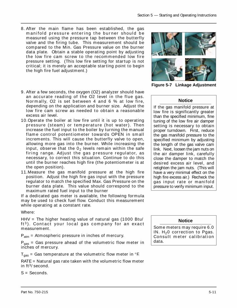
Section 5 — Starting and Operating Instructions
Part No. 750-215 5-11
8. After the main flame has been established, the gasmanifold pressure entering the burner should bemeasured using the pressure tap between the butterflyvalve and the firing tube. This measurement should becompared to the Min. Gas Pressure value on the burnerdata plate. Obtain a stable operating point by adjustingthe low fire cam screw to the recommended low firepressure setting. (This low fire setting for startup is notcritical; it is merely an acceptable starting point to beginthe high fire fuel adjustment.)
9. After a few seconds, the oxygen (O2) analyzer should havean accurate reading of the O2 level in the flue gas.Normally, O2 is set between 4 and 6 % at low fire,depending on the application and burner size. Adjust thelow fire cam screw as needed to obtain a reasonableexcess air level.
10.Operate the boiler at low fire until it is up to operatingpressure (steam) or temperature (hot water). Thenincrease the fuel input to the boiler by turning the manualflame control potentiometer towards OPEN in smallincrements. This will cause the butterfly valve to open,allowing more gas into the burner. While increasing theinput, observe that the 02 levels remain within the safefiring range. Adjust the gas pressure regulator, asnecessary, to correct this situation. Continue to do thisuntil the burner reaches high fire (the potentiometer is atthe open position).
11.Measure the gas manifold pressure at the high fireposition. Adjust the high fire gas input with the pressureregulator to match the specified Max. Gas Pressure on theburner data plate. This value should correspond to themaximum rated fuel input to the burner
If a dedicated gas meter is available, the following formulamay be used to check fuel flow. Conduct this measurementwhile operating at a constant rate.
Where:
HHV = The higher heating value of natural gas (1000 Btu/ft3) . Contact your local gas company for an exactmeasurement.
Patm = Atmospheric pressure in inches of mercury.
Pgas = Gas pressure ahead of the volumetric flow meter ininches of mercury.
Tgas = Gas temperature at the volumetric flow meter in °F.
RATE = Natural gas rate taken with the volumetric flow meterin ft3/second.
S = Seconds.
Figure 5-7 Linkage Adjustment
NoticeIf the gas manifold pressure atlow fire is significantly greaterthan the specified minimum, finetuning of the low fire air dampersetting is necessary to obtainproper turndown. First, reducethe gas manifold pressure to thespecified minimum by adjustingthe length of the gas valve camlink. Next, loosen the jam nuts onthe air damper link, carefullyclose the damper to match thedesired excess air level, andretighten the jam nuts. (This willhave a very minimal effect on thehigh fire excess air.) Recheck thegas inpu t ra te o r man i fo ldpressure to verify minimum input.
NoticeSome meters may require 6.0IN. H20 correction to Pgas.Consult meter calibrationdata.
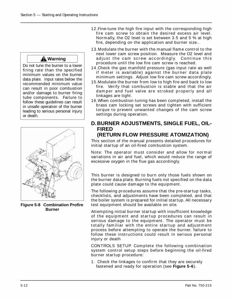
Section 5 — Starting and Operating Instructions
5-12 Part No. 750-215
12.Fine-tune the high fire input with the corresponding highfire cam screw to obtain the desired excess air level.Normally, the O2 level is set between 3.5 and 5 % at highfire, depending on the application and burner size..
13.Modulate the burner with the manual flame control to thenext lower cam screw position. Measure the O2 level andadjust the cam screw accordingly. Continue thisprocedure until the low fire cam screw is reached.
14.Check the gas manifold pressure (gas input rate as wellif meter is available) against the burner data plateminimum settings. Adjust low fire cam screw accordingly.
15.Modulate the burner from low to high fire and back to lowfire. Verify that combustion is stable and that the airdamper and fuel valve are stroked properly and alllinkages are tight.
16.When combustion tuning has been completed, install thebrass cam locking set screws and tighten with sufficienttorque to prevent unwanted changes of the cam screwsettings during operation.
D.BURNER ADJUSTMENTS, SINGLE FUEL, OIL-FIRED(RETURN FLOW PRESSURE ATOMIZATION)
This section of the manual presents detailed procedures forinitial startup of an oil-fired combustion system.
Note: The operator must consider and allow for normalvariations in air and fuel, which would reduce the range ofexcessive oxygen in the flue gas accordingly.
This burner is designed to burn only those fuels shown onthe burner data plate. Burning fuels not specified on the dataplate could cause damage to the equipment.
The following procedures assume that the pre-startup tasks,checklists, and adjustments have been completed, and thatthe boiler system is prepared for initial startup. All necessarytest equipment should be available on site.
Attempting initial burner startup with insufficient knowledgeof the equipment and startup procedures can result inserious damage to the equipment. The operator must betotally familiar with the entire startup and adjustmentprocess before attempting to operate the burner. failure tofollow these instructions could result in serious personalinjury or death
CONTROLS SETUP. Complete the following combinationsystem control setup steps before beginning the oil-firedburner startup procedure:
1. Check the linkages to confirm that they are securely fastened and ready for operation (see Figure 5-6).
! WarningDo not tune the burner to a lowerfiring rate than the specifiedminimum values on the burnerdata plate. Input rates below therecommended minimum valuecan result in poor combustionand/or damage to burner firingtube components. Failure tofollow these guidelines can resultin unsafe operation of the burnerleading to serious personal injuryor death.
Figure 5-8 Combination Profire Burner
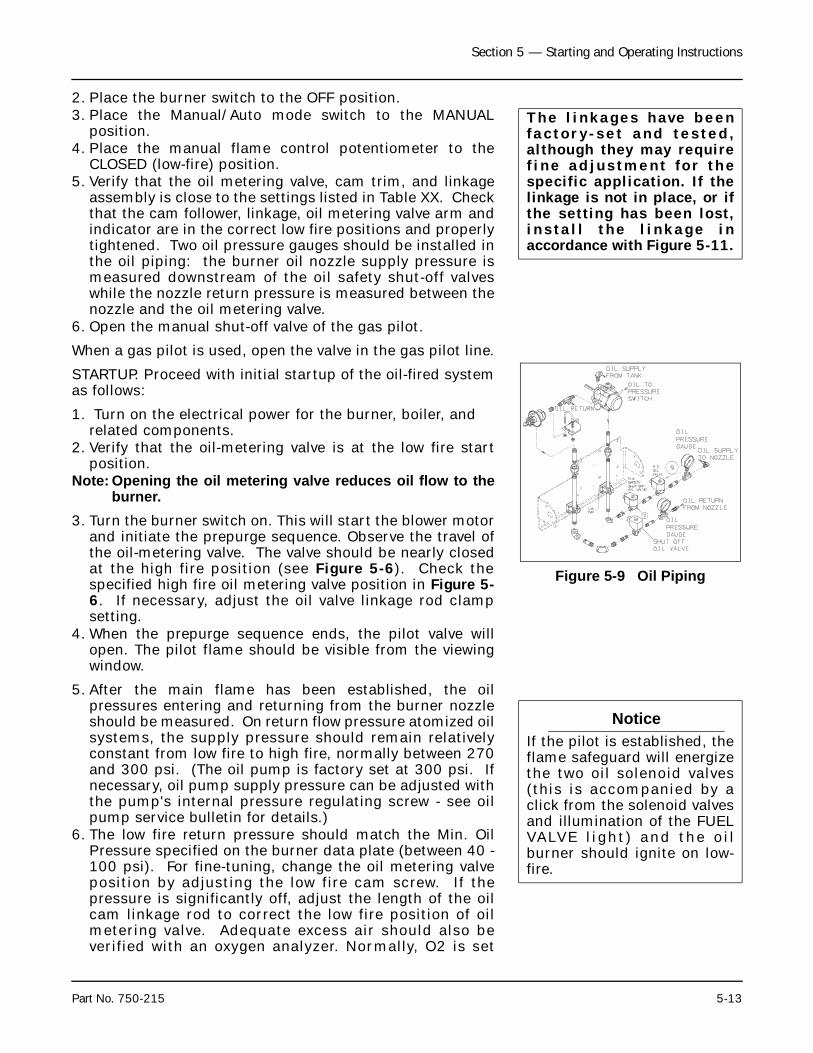
Section 5 — Starting and Operating Instructions
Part No. 750-215 5-13
2. Place the burner switch to the OFF position.3. Place the Manual/Auto mode switch to the MANUAL
position.4. Place the manual flame control potentiometer to the
CLOSED (low-fire) position.5. Verify that the oil metering valve, cam trim, and linkage
assembly is close to the settings listed in Table XX. Checkthat the cam follower, linkage, oil metering valve arm andindicator are in the correct low fire positions and properlytightened. Two oil pressure gauges should be installed inthe oil piping: the burner oil nozzle supply pressure ismeasured downstream of the oil safety shut-off valveswhile the nozzle return pressure is measured between thenozzle and the oil metering valve.
6. Open the manual shut-off valve of the gas pilot.
When a gas pilot is used, open the valve in the gas pilot line.
STARTUP. Proceed with initial startup of the oil-fired systemas follows:
1. Turn on the electrical power for the burner, boiler, and related components.
2. Verify that the oil-metering valve is at the low fire startposition.
Note: Opening the oil metering valve reduces oil flow to theburner.
3. Turn the burner switch on. This will start the blower motorand initiate the prepurge sequence. Observe the travel ofthe oil-metering valve. The valve should be nearly closedat the high fire position (see Figure 5-6). Check thespecified high fire oil metering valve position in Figure 5-6. If necessary, adjust the oil valve linkage rod clampsetting.
4. When the prepurge sequence ends, the pilot valve willopen. The pilot flame should be visible from the viewingwindow.
5. After the main flame has been established, the oilpressures entering and returning from the burner nozzleshould be measured. On return flow pressure atomized oilsystems, the supply pressure should remain relativelyconstant from low fire to high fire, normally between 270and 300 psi. (The oil pump is factory set at 300 psi. Ifnecessary, oil pump supply pressure can be adjusted withthe pump's internal pressure regulating screw - see oilpump service bulletin for details.)
6. The low fire return pressure should match the Min. OilPressure specified on the burner data plate (between 40 -100 psi). For fine-tuning, change the oil metering valveposition by adjusting the low fire cam screw. If thepressure is significantly off, adjust the length of the oilcam linkage rod to correct the low fire position of oilmetering valve. Adequate excess air should also beverified with an oxygen analyzer. Normally, O2 is set
The l inkages have beenfac tor y -se t and tes ted ,although they may requiref ine ad jus tment fo r thespecific application. If thelinkage is not in place, or ifthe setting has been lost,ins ta l l the l inkage inaccordance with Figure 5-11.
Figure 5-9 Oil Piping
NoticeIf the pilot is established, theflame safeguard will energizethe two oil solenoid valves(this is accompanied by aclick from the solenoid valvesand illumination of the FUELVALVE l ight ) and the o i lburner should ignite on low-fire.
Section 5 — Starting and Operating Instructions
5-14 Part No. 750-215
between 4 and 6 % at low fire, depending on theapplication and burner size.
7. Operate at low fire until it is thoroughly warmed. Then,one cam screw at a time, modulate to high fire with themanual flame control. This will cause the oil meteringvalve to close, resulting in an increase in the return line oilpressure. Check the excess air in the flue gas whilemodulating to high fire (maintain O2 levels between 4 - 6% ). Make cam screw adjustments as needed to maintainadequate excess air.
8. Verify that the high fire supply pressure stays between 280to 300 psi. (The oil pump is factory set at 300 psi. Ifnecessary, oil pump supply pressure can be adjusted withthe pump's internal pressure regulating screw - see oilpump service bulletin for details.)
9. Set the high fire oil return pressure to match the specifiedburner data plate Max. Oil Pressure setting (usually in therange of 160 - 220 psi) by adjusting the correspondingcam screw to open or close the oil-metering valve, asnecessary.
10.Check the high fire excess air level. Normally, the O2level is set between 3.5 and 5 % at high fire, depending onthe application and burner size
11.Modulate the burner with the manual flame control to thenext lower cam screw position. Measure the O2 level atintermediate screw positions and adjust each cam screwto maintain between 3.5 to 5 %. Continue this procedureuntil the low fire cam screw is reached.
12.Verify that the low fire return oil pressure is at the burnerdata plate specified minimum pressure. Excess air levelshould be set between 4 to 6 % O2. Fine tune by adjustingthe low fire cam screw accordingly.
13.Following combustion setup, tighten all linkages. Checkfor smooth light off by cycling the burner through the pre-purge sequence again. During pre-purge, verify that alllinkages, dampers and valves operate smoothly withoutinterference or binding. Verify that the pilot flame issufficient and the burner lights off smoothly.
14.Modulate and recheck combustion air at different firingrate positions. Smoke spot measurements should be lessthan a No. 2 (Bacharach).
15.When combustion tuning has been completed, install thebrass cam locking set screws and tighten with sufficienttorque to prevent unwanted changes of the cam screwsettings during operation.
E. BURNER ADJUSTMENTS, COMBINATION GAS AND OIL
Note: The operator must consider and allow for normalvariations in air and fuel, which would reduce the rangeof excessive oxygen in the flue gas accordingly.
NoticeIf the excess air significantlydeviates from the recommendedO2 level after making the properlow fire oil valve adjustment, finetuning of the low fire air dampersetting is necessary to obtainproper turndown. Loosen the jamnuts on the air damper link,carefully adjust the damper tomatch the desired excess airlevel, and retighten the jam nuts.(This will have a very minimaleffect on the high fire excess air.)Recheck the low fire oil returnpressure to verify minimum input.
NoticeBurner input can be verified withthe use of oil meters in the supplyand return lines from the burnernozzle. The flow rate measured inthe return line must be subtractedfrom the flow rate measured inthe supply line. Following start-up, it is strongly recommendedthat the flow meters be removedfrom the system.
Section 5 — Starting and Operating Instructions
Part No. 750-215 5-15
This section of the manual presents procedures to befollowed for initial startup of a combination ProFire burner.
These procedures assume that the pre-startup tasks,checklists, and adjustments have been completed, and thatthe boiler system is prepared for initial startup. All necessarytest equipment should be available on site.
In general, the combination fueled system is to be startedfirst using oil, because, as a fuel, oil has a greatercombustion air requirement than natural gas. After beingcompletely adjusted for oil combustion, the burner is re-started and adjusted using natural gas as fuel. Combustionadjustment of the combination burner for natural gasinvolves balancing the input gas rates only against theexisting flow of combustion air, as established initially for oil-firing. Do not readjust the air shutters when tuning thecombination burner for combustion of natural gas.
CONTROLS SETUP. Complete the following system controlsetup steps before beginning the combination burnerstartup procedure:
1. Check the linkages to confirm that they are securely fastened and ready for operation.
NOTE: The linkages have been factory-set and tested,although they may require fine tuning for the specificapplication. If the linkage is not in place, or if the setting hasbeen lost, install the linkage in accordance with Figure 5-6.
2. Place the burner switch in the OFF position.3. Place the Modulating Mode switch in the MANUAL
position.4. Place the manual flame potentiometer in the CLOSE (low-
fire) position.5. Verify that the oil metering valve, gas valve, cam trim and
associated linkage assemblies are close to the settingslisted in Figure 5-6. Check that the cam followers,linkages, valve arms and indicators are in the correct lowfire positions and properly tightened. Two oil pressuregauges should be installed in the oil piping: the burner oilnozzle supply pressure is measured downstream of the oilsafety shut-off valves while the nozzle return pressure ismeasured between the nozzle and the oil metering valve.The slot in the gas valve shaft should be 5 to 10% open atthe low fire position.
6. Open the manual shut-off valve of the gas pilot.
STARTUP. Proceed with initial startup using oil as follows:
1. Position the fuel selector switch to "OIL".2. Proceed with startup and combustion adjustments using
the same procedures defined for oil-fired burners.
! CautionThis burner is designed toburn only those fuels shownon the burner data plate.Burning fuels not specified onthe data plate could causedamage to the equipment.
! WarningAttempting initial burnerstar tup with insuf f ic ientknowledge of the equipmentand startup procedures canresult in serious damage. Theoperator must be total lyfami l i a r w i th the en t i res ta r tup and ad jus tmentprocess before attempting tooperate the burner.
Section 5 — Starting and Operating Instructions
5-16 Part No. 750-215
3. After the system has been completely adjusted for oil-firing, place the burner switch to the off position, andposition the fuel selector switch to GAS.
4. Place the Manual/Auto mode switch to the MANUALposition.
5. Place the manual flame control potentiometer to theCLOSE (low-fire) position.
6. Close the downstream manual shutoff valve on the burnergas train (closest to the burner).
7. Admit natural gas to the gas train.8. Verify that the butterfly valve is in a position that is nearly
closed.9. Proceed with startup and combustion adjustment
procedures as described for gas-fired burners. Onlyadjustments to the gas valve linkage settings should beundertaken at this point. No adjustments should be madeto the air damper linkage settings. Changes to the airdamper settings could adversely effect oil combustiontuning.
10.When combustion tuning has been completed on bothfuels, install the brass cam locking set screws and tightenwith sufficient torque to prevent unwanted changes of thecam screw settings during operation.
Turn the burner switch on. This will start the blower motorand initiate the prepurge sequence.
When the prepurge sequence ends, the pilot valve will open.The pilot flame should be visible from the viewing window.
When the pilot is established, the flame safeguard willenergize the main gas valve (this is accompanied by fuelvalve activity and illumination of the FUEL VALVE light). Themain gas valve should be visually checked by observing thestem move from the CLOSED to the OPEN position.
NOTE: The downstream manual gas shutoff valve should bein the closed position, for initial boiler startup, to ensureproper operation of the automatic gas valves. This valve canthen be slowly opened when the pilot is established andproven.
After the main flame has been established, the gas pressureentering the burner should be read (using the pressure tapbetween the butterfly valve and the blast tube) to determinean initial estimate of the gas input rate. By doing so, andreferring to Figure 5-10, an approximation of the burnerinput can be assessed. Obtain a stable operating point byadjusting the butterfly valve to the pressure indicated inFigure 5-10 and select the temporary firing rate. This rate forstartup is not critical, but merely an acceptable startingpoint to begin the high fire adjustment procedures.
After a few seconds, the O2 analyzer should have an accuratereading of the O2 present in the flue gas. Table 5-1 provides
Section 5 — Starting and Operating Instructions
Part No. 750-215 5-17
a representation of the acceptable O2 range for the gasburner. Normally, the O2 levels are set between 3 and 5percent at low fire, depending on the application and burnersize (see the burner specification plate for the minimumfiring rate).
Operate the boiler at low fire until it is thoroughly warmed.Then increase the fuel input to the boiler by turning themanual f lame potentiometer towards open in smallincrements. This will cause the butterfly valve to openfarther, allowing more gas into the burner. While increasingthe input, observe that the O2 levels remain within the rangeshown in Table 5-1. Adjust the gas pressure regulator, asnecessary, to correct this situation. Continue to do this untilthe burner reaches high fire (the potentiometer is at theopen position).
Adjust the high fire gas input to match the maximum rating.At high fire, the butterfly valve should be near the full openposition (readjust linkage if required). Adjust the gaspressure to obtain the correct fuel input. (Maximumpressure specified on the burner specification plate.)
If a dedicated gas meter is available, the following formulamay be used to check fuel flow. Conduct this measurementwhile operating at a constant rate.
NOTE: Some meters may require 6.0 IN. H20 correction toPgas. Consult meter calibration data.
Where:
HHV = The higher heating value of natural gas (1000 Btu/ft3) . Contact your local gas company for an exactmeasurement.
Patm = Atmospheric pressure in inches of mercury.
Pgas = Gas pressure ahead of the volumetric flow meter ininches of mercury.
Tgas = Gas temperature at the volumetric flow meter in °F.
RATE = Natural gas rate taken with the volumetric flow meterin ft3/second
S = Seconds.
NOTE: It is unnecessary to readjust the position of the high-fire or low-fire shutters after having been set for oil firing.
Modulate the burner to low fire. The butterfly valve should beadjusted to provide the correct fuel pressure at the low-fireposition in accordance with the burner data plate minimumgas-pressure rating.
FUEL FLOW ADJUSTMENTS. Fuel flow rates are adjusted toprovide the design-rated heat inputs into the burner at bothhigh-fire (maximum rate) and low-fire (minimum rate)operating conditions. The maximum and minimum fuel inputflow rates for the burner are identified on the data plate (see
Section 5 — Starting and Operating Instructions
5-18 Part No. 750-215
Figure 5-8). Natural gas flow rates are specified in cfh (cubicfeet per hour), and fuel oil flow rates are specified in gph(gallons per hour).
Fuel flow rate adjustment for both natural gas and oil isaccomplished by regulating the fuel pressure against a fixeddiameter orifice (nozzle). The methods for accomplishingthe pressure regulation, however, are different for natural gasand oil.
The method for regulating the natural gas flow rate (manifoldpressure) is as follows:
Maximum flow rate is established by operating the burner athigh-fire with the butterfly valve fully open, then adjustingthe manifold pressure to the maximum as specified on thedata plate. Maximum manifold pressure is obtained byadjusting the main gas pressure regulator on the gas trainwhile operating the burner at high-fire.
Gas flow modulation for turndown is accomplished bythrottling the flow rate with the butterfly valve. The flowrestriction of the partially closed butterfly valve reduces theflow of gas through the burner nozzle. The butterfly valvethrottling position is controlled by linkage from the main airshutter shaft, which is operated by the modulating motor.
With the modulating motor positioned for low-fire operation,the butterfly valve linkage is adjusted to provide theminimum pressure in the nozzle manifold, as specified onthe burner data plate.
The method for regulating the fuel-oil flow rate (nozzlepressure) is as follows:
Maximum flow rate is established by operating the burner athigh-fire with the oil metering valve in a nearly closedposition with the modulating motor set at the high-fireposition. In this position, the flow of fuel oil through the oilby-pass is minimal, resulting in nearly maximum flowpressure from the pump. High-fire oil flow adjustment isaccomplished by adjusting the linkage to the oil meteringvalve so that the burner nozzle pressure equals themaximum oil pressure specification on the burner data plate(see Figure 5-8).
Oil pressure modulation for turndown to low-fire operation isaccomplished by increasing the flow rate of oil through theoil by-pass loop, which reduces pressure in the burnernozzle. This is accomplished by setting the modulatingmotor to the low-fire position, which causes the oil meteringvalve to open. While in this position, the oil metering valvelinkage can be adjusted so that the burner nozzle pressureequals the minimum oil pressure specification on the burnerspecification plate (see Figure 5-8).
Section 5 — Starting and Operating Instructions
Part No. 750-215 5-19
F. STARTUP, OPERATING AND SHUTDOWN - ALL FUELS
Depending upon the fuel being burned, the applicableprevious sections in Chapter 5 should be reviewed forpreliminary instructions.
The fuel selector switch should be, accordingly, set to eitheroil or gas.
Set the manual-automatic switch (Figure 2-1) to “manual”and turn the manual flame control to “close.”
Turn burner switch to “ON.” The load demand light shouldglow. The low-water level light should remain out, indicatinga safe water level in the boiler. The programmer is nowsequencing. See Chapter 4 for sequence details.
On an initial starting attempt, several efforts might berequired to accomplish “bleeding” of fuel lines, main or pilot.If ignition does not then occur, do not repeat unsuccessfulattempts without rechecking the burner and pi lotadjustment.
On ignition failure, the flame failure light will glow and theblower will purge the boiler of unburned fuel vapors beforestopping. After ignition failure, wait a few moments beforere-setting the lockout switch.
Do not re-light the pilot or attempt to start the main burner,either oil or gas, if the combustion chamber is hot and/or ifgas or oil vapor combustion gases are present in the furnaceor flue passages. Failure to follow these instructions couldresult in serious personal injury or death.
The burner and control system is designed to provide a “pre-purge” period of fan operation prior to establishing ignitionspark and pilot flame. Do not attempt to alter the system ortake any action that might circumvent the “pre-purge”feature. Failure to follow these instructions could result inserious personal injury or death.
After main flame ignition, the burner should be set onmanual control at its low fire setting (that is, with manualflame control at “close”) until the boiler is properly warmed.In the case of a steam boiler, CLOSE THE VENT VALVE whenthe steam begins to appear.
A hot water boiler must have a continuous flow of systemwater through the vessel during the warm-up period. Theentire water content of the system and boiler must bewarmed prior to increasing fuel input.
If the flame at low fire provides insufficient heat to reachnormal operating pressure or temperature after 30 minutes,gradually increase the firing rate by turning the manual
Section 5 — Starting and Operating Instructions
5-20 Part No. 750-215
flame control in one point increments. Operate at theincreased fuel input rate for a period of time until an increaseis noted in pressure or temperature.
After the boiler is thoroughly warmed, turn the manual flamecontrol to high fire. At this point a combustion analysisshould be made, with instruments, and fuel flow regulated asrequired. Refer to the adjustment procedures in Chapter 6.After making the high-fire adjustment, manually decreasethe firing rate to analyze combustion gases, and adjust asrequired.
To properly perform the testing and adjusting, it is necessarythat the burner be allowed to fire at a maximum rate longenough to achieve desired results.
Operating - Normal operation of the burner should be withthe switch in the automatic position and under the directionof the modulating control. The manual position is providedfor initial adjustment of the burner over the entire firingrange. When a shutdown occurs while operating in themanual position at other than low fire, the damper will notbe in a closed position, thus allowing more air than desiredto flow through the boiler. The hot flame to cool air cyclingsubjects the pressure vessel metal and refractory toundesirables conditions.
With the switch set at “auto,” the burner will operate on amodulating basis according to the load demand.
The burner will continue to operate with modulated firinguntil the operating limit pressure or temperature is reached,unless:
The burner is manually turned “off.”
A low-water condition is detected by low-water level control.
The electrical or fuel supply is interrupted.
The combustion air pressure drops below minimum level.
There can be other reasons for shutdown such as motoroverload, flame outages, tripped circuit breakers, blownfuses, or through other interlock devices in the circuitry.
When the burner is shut down normally, by either theoperating limit control or by manually switching the burneroff, the load demand light no longer glows.
Shutdown through conditions causing safety or interlockcontrols to open will actuate the flame failure light (andalarm if so equipped) and the load demand light will remainlit. The cause of this type of shutdown will have to be located,investigated, and corrected before operation can beresumed. Refer to the troubleshooting section in Chapter 7.
Section 5 — Starting and Operating Instructions
Part No. 750-215 5-21
Shutdown - When the operating limit control setting isreached to open the circuit or if the burner switch is turned“off,” the following sequence occurs.
The fuel valve is deenergized and the flame is extinguished.The timer begins operation and the blower motor continuesrunning to force air through the furnace in the post-purgeperiod.
At the end of the programmed post-purge period, the blowermotor is turned off. The timer has returned to its originalstarting position and stops. The unit is ready to re-start.
It is advisable to check for tight shut-off of fuel valves.Despite precautions and strainers, foreign material in eithernew or renovated fuel lines may lodge under a valve seat andprevent tight closure. The situation is especially true in newinstallations. Promptly correct any conditions causingleakage. Failure to follow these instructions could result inserious personal injury or death
G. CONTROL OPERATIONAL TEST AND CHECKS
Proper operation of the various controls should be verifiedand tested when the boiler is initially placed into service, orwhenever a control is replaced. Periodic checks should bemade thereafter in accordance with a planned maintenanceprogram.
The operating limit control may be checked by allowingsteam pressure to increase until the burner shuts down.Depending upon the load, it may be necessary to manuallyincrease the firing rate to raise steam pressure to the burnershut off point. If the load is heavy, the header valve can beclosed or throttled until the pressure increases. Observe thesteam gauge to check the cut off pressure as the operatinglimit control shuts the burner down. Slowly open the headervalve to release steam pressure and check the cut-in settingas the burner restarts. Check the modulating control for thedesired operating pressure range. See Chapter 6 forinstructions on the adjustment of controls.
The water temperature on a hot water boiler that may beoperating at less than full load may be raised by manuallyincreasing the firing rate until the burner shuts down throughthe action of the operating limit control. Observe thethermometer to verify the desired settings at the point of cut-out and again when the burner restarts. Return the manualautomatic switch to “automatic” and check the modulatingcontrol for the desired temperature range. See Chapter 6 forinstructions on the adjustment of the controls.
Check the proper operation and setting of the low-watercutoff and the auxiliary low water cutoff (and pumpoperating control, if used).
Proper operation of the flame failure device should bechecked at startup and at least once a week thereafter. Refer
Section 5 — Starting and Operating Instructions
5-22 Part No. 750-215
to Chapter 8 for information on flame safety checks. Checkthe program relay’s annunciation for any system failure.Observe the promptness of ignition of the pilot flame and themain flame.
Milwaukee, Wisconsin
www.cleaver-brooks.com
Section 6Adjustment and Maintenance
A. General . . . . . . . . . . . . . . . . . . . . . . . . . . . . . . . . . . . . . . . . . . . 6-2B. Periodic Inspection . . . . . . . . . . . . . . . . . . . . . . . . . . . . . . . . . . . 6-3C. Water Level Controls and Waterside of Pressure Vessel . . . . . . . . . . . 6-3D. Water Gauge Glass . . . . . . . . . . . . . . . . . . . . . . . . . . . . . . . . . . . 6-5E. Operating Controls . . . . . . . . . . . . . . . . . . . . . . . . . . . . . . . . . . . . 6-5
1. Setting and Adjusting . . . . . . . . . . . . . . . . . . . . . . . . . . . . . 6-62. Pressure Controls — Steam Boiler . . . . . . . . . . . . . . . . . . . . 6-73. Temperature Controls — Hot Water Boiler . . . . . . . . . . . . . . . 6-94. Combustion Air Proving Switch . . . . . . . . . . . . . . . . . . . . . 6-105. Low Gas Pressure Switch . . . . . . . . . . . . . . . . . . . . . . . . . 6-116. High Gas Pressure Switch . . . . . . . . . . . . . . . . . . . . . . . . . 6-117. Low Oil Pressure Switch (Optional) . . . . . . . . . . . . . . . . . . . 6-118. Programming Control . . . . . . . . . . . . . . . . . . . . . . . . . . . . 6-119. Control Operational Test . . . . . . . . . . . . . . . . . . . . . . . . . . 6-13
F. Oil Burner . . . . . . . . . . . . . . . . . . . . . . . . . . . . . . . . . . . . . . . . . 6-141. General . . . . . . . . . . . . . . . . . . . . . . . . . . . . . . . . . . . . . . 6-142. Oil Pump . . . . . . . . . . . . . . . . . . . . . . . . . . . . . . . . . . . . . 6-153. Combustion Adjustment — Oil . . . . . . . . . . . . . . . . . . . . . . 6-16
G. Gas Burner . . . . . . . . . . . . . . . . . . . . . . . . . . . . . . . . . . . . . . . . 6-171. General . . . . . . . . . . . . . . . . . . . . . . . . . . . . . . . . . . . . . . 6-172. Gas Pilot Flame Adjustment . . . . . . . . . . . . . . . . . . . . . . . 6-173. Gas Pressure and Flow Information . . . . . . . . . . . . . . . . . . 6-194. Combustion Adjustment — Gas . . . . . . . . . . . . . . . . . . . . . 6-22
H. Damper Motor and Auxiliary Switches . . . . . . . . . . . . . . . . . . . . . 6-24I. Air Damper Adjustment . . . . . . . . . . . . . . . . . . . . . . . . . . . . . . . . 6-26J. Safety Valves . . . . . . . . . . . . . . . . . . . . . . . . . . . . . . . . . . . . . . . 6-28K. Motorized Gas Valve . . . . . . . . . . . . . . . . . . . . . . . . . . . . . . . . . . 6-29L. Solenoid Valves: Gas Pilot/Fuel Oil/Vent Valves . . . . . . . . . . . . . . . 6-30M. Refractory . . . . . . . . . . . . . . . . . . . . . . . . . . . . . . . . . . . . . . . . 6-30N. Fuel Changeover Maintenance . . . . . . . . . . . . . . . . . . . . . . . . . . 6-31O. Forced Draft Fan . . . . . . . . . . . . . . . . . . . . . . . . . . . . . . . . . . . . 6-31P. Furnace Access and Fireside Cleaning . . . . . . . . . . . . . . . . . . . . . . 6-31
Section 6 — Adjustment and Maintenance
6-2 Part No. 750-215
A.GENERALWhile each boiler is tested for correct operation beforeshipment from the factory, variable conditions, such asburning characteristics of the fuel used and operating loadconditions, require further adjustment after installation toassure maximum operating efficiency and economy. Prior toplacing the boiler into initial service, a complete inspectionshould be made of all controls, connecting piping, wiring,and all fastenings such as nuts, bolts and setscrews to besure that no damage or misadjustments occurred duringshipment and installation.
A well planned maintenance program avoids unnecessarydowntime or costly repairs, promotes safety and aids boilercode and local inspectors. An inspection schedule with al ist ing of procedures should be establ ished. I t isrecommended that a boi ler room log or record bemaintained, recording daily, weekly, monthly and yearlymaintenance activities. This provides a valuable guide andaids in obtaining economies and length of service fromCleaver-Brooks equipment.
Even though the boiler has electrical and mechanical devicesthat make it automatic or semi-automatic in operation, thesedevices require systematic and periodic maintenance. Any“automatic” features do not relieve the operator fromresponsibility, but rather free him of certain repetitivechores, providing him time to devote to upkeep andmaintenance.
Good housekeeping helps maintain a professional appearingboiler room. Only trained and authorized personnel shouldbe permitted to operate, adjust or repair the boiler and itsrelated equipment. The boiler room should be kept free of allmaterial and equipment not necessary to the operation ofthe boiler or heating system.
Alertness in recognizing an unusual noise, improper gaugereading, leaks, etc., can make the operator aware of animproper condition, permitting prompt corrective actionthat may prevent extensive repairs or unexpected downtime.Any steam, water or fuel leaks should be repaired as soon asthey are noticed. Leaks are wasteful as well as hazardous.Include in the program preventive maintenance measuressuch as regularly checking the tightness of connections,locknuts, setscrews, packing glands, etc.
The air-fuel ratio should be checked often since this will alertthe operator to losses in combustion efficiency which do notproduce v is ible f lame changes. Var iat ions in fuelcomposition from one time to another may requirereadjustment of the burner. A combustion analyzer shouldbe used to adjust fuel input for maximum operatingefficiency and economy.
Section 6 — Adjustment and Maintenance
Part No. 750-215 6-3
B.PERIODIC INSPECTIONInsurance regulations or local laws require a periodicinspection of the pressure vessel by an authorized inspector.
Section 3 contains information relative to this inspection.
Inspections of this type are usually, though not necessarily,scheduled for periods of normal boiler downtime such as anoff-season. This major inspection can often be used toaccomplish maintenance, replacements or repairs thatcannot easily be done at other times. This also serves as agood basis for establishing a schedule for annual, monthly orother periodic maintenance programs.
While this inspection pertains primarily to the waterside andfireside surfaces of the pressure vessel, it provides theoperator an excellent opportunity for detailed inspection ofall components of the boiler including piping, valves, pumps,gaskets, refractory, etc. Comprehensive cleaning, spotpainting or repainting and the replacement of expendableitems should be planned for and taken care of during thistime. Any major repairs or replacements that may berequired should also, if possible, be coordinated with thisperiod of boiler shutdown.
Replacement spare parts, if not on hand, should be orderedsufficiently prior to shutdown.
Cleaver-Brooks boilers are designed, engineered and built togive long life and excellent service on the job. Good operatingpractices and conscientious maintenance and care willobtain efficiency and economy from their operation andcontribute to long years of performance.
C.WATER LEVEL CONTROLS AND WATERSIDE OF PRESSURE VESSEL
The need to periodically check water level controls and thewaters ide of the pressure vesse l cannot be over-emphasized. Most instances of major boiler damage are theresult of operating with low water or the use of untreated (orincorrectly treated) water.
Always be sure of the boiler water level. The water columnshould be blown down routinely. Check samples of boilerwater and condensate in accordance with proceduresrecommended by your water consultant. Refer to Section Hand Section in Section3 for blowdown instructions andinternal inspection procedures.
A typical water level control is mounted in the water columnand has float actuated switches. One switch is connected tothe burner limit circuit and will stop the burner if a low watercondition occurs. On a steam boiler the other switch isconnected to the feedwater circuit to energize a water pumpor feeder valve to maintain water at the proper operatinglevel.
Section 6 — Adjustment and Maintenance
6-4 Part No. 750-215
Usually, the control is of the automatic reset type and willremake the limit circuit when the water level is restored.Some applications require that a control be equipped with amanual reset mechanism that must be manually reset beforethe burner can be restarted. This is usually accomplishedwith the use of a second or auxiliary control that has thisfeature.
Since low water cutoff devices are generally set by theoriginal manufacturer, no attempt should be made to adjustthese controls to alter the point of low water cutoff or pointof pump cut-in or cut-out. If a low water device shouldbecome erratic in operation or if its setting changes fromprevious established levels, check for reasons and correct,repair or replace as required.
These controls normally function for long periods of timewhich may lead to laxity in testing on the assumption thatnormal operation will continue indefinitely.
The controls’ operation may be checked by stopping thewater supply to the boiler while the burner is operating at lowfire. While under constant attendance allow the water tolower at a normal rate. If a control does not break the circuitto stop the burner at the proper point, then SHUT DOWNTHE BURNER IMMEDIATELY.
Do not restart until all cross connecting piping is checked forobstructions. Also check the float bowl. If these are clean,repair or replace the control.
Repeat the above test to insure proper operation prior toreturning the boiler to service.
On a steam boiler, the head mechanism of the low watercutoff device(s) should be removed from the bowl at leastonce a month to check and clean the float ball, the internalmoving parts, and the bowl or water column.
Remove the pipe plugs from the tees or crosses and makecertain the cross connecting piping is clean and free ofobstructions. Controls must be mounted in a plumb positionfor proper performance. Determine that piping is verticallyaligned after shipment and installation and throughout life ofequipment.
A scheduled blowdown of the water controls on a steamboiler should be maintained.
It is impractical to blowdown the low water cutoff devices ona hot water boiler since the entire water content of thesystem would become involved. Many hot water systems arefully closed and any loss of water will require make-up andadditional feedwater treatment that might not otherwise benecessary. Since the boiler and system arrangement usuallymakes it impractical to perform daily and monthlymaintenance of the low water cutoff devices, it is essential toremove the operating mechanism from the bowl annually or
Section 6 — Adjustment and Maintenance
Part No. 750-215 6-5
more frequently, if possible, to check and clean float ball,internal moving parts, and the bowl housing. Also check thecross connecting piping to make certain that it is clean andfree of obstruction.
D.WATER GAUGE GLASSA broken or discolored glass must be replaced at once.Periodic replacement should be a part of the maintenanceprogram. Always use new gaskets when replacing a glass.Use a proper size rubber packing. Do not use “loosepacking” which could be forced below the glass and possiblyplug the valve opening.
Close the valves when replacing the glass. Slip a packing nut,a packing washer, and packing ring onto each end of theglass. Insert one end of the glass into the upper gauge valvebody far enough to allow the lower end to be dropped intothe lower body. Slide the packing nuts onto each valve andtighten.
If the glass is replaced while the boiler is in service, open theblowdown and slowly bring the glass to operatingtemperature by cracking the gauge valves slightly. After glassis warmed up, close the blowdown valve and open the gaugevalves completely.
Check try-cocks and gauge cocks for freedom of operationand clean as required. It is imperative that the gauge cocksare mounted in exact alignment. If they are not, the glass willbe strained and may fail prematurely.
A blowdown cock is provided on the lower gauge glass fittingand a daily blowdown is recommended.
E. OPERATING CONTROLSIn general, when adjusting controls check to see that they arelevel, especially those containing mercury switches. Ontemperature sensing controls make sure that the bulb isproperly bottomed in its well. Make sure that connectingtubing is not kinked or damaged.
Controls are carefully calibrated during their manufactureand do not normally require re-calibration. The dial settingsare generally quite accurate although it is not unusual tohave a slight variation between a scale setting and an actualpressure gauge or thermometer reading and to re-adjustcontrol setting to agree with these readings. This ispredicated, however, on pressure gauges and thermometersbeing accurate.
Most of the operat ing contro ls require ver y l i t t lemaintenance beyond occasional inspection. Examinetightness of electrical connections. Keep controls clean. Ifany dust accumulates in the interior of the control, removewith a low pressure air hose taking care not to damage themechanism.

Section 6 — Adjustment and Maintenance
6-6 Part No. 750-215
Examine any mercury tube switches for damage or cracks:this condition, indicated by a dark scum over the normallybright surface of the mercury, may lead to erratic switchingaction. Make certain that controls of this nature are correctlyleveled using the leveling indicator if provided. Pipingleading to various controls actuated by pressure should becleaned if necessary. Covers should be left on controls at alltimes.
Dust and dirt can cause excessive wear and overheating ofmotor starter and relay contacts and maintenance of theseis a requirement. Starter contacts are plated with silver andare not harmed by discoloration and slight pitting. Do notuse files or abrasive materials such as sandpaper on thecontact points since this only wastes the metallic silver withwhich the points are covered. Use a burnishing tool or a hardsurface paper to clean and polish contacts. Replacement ofthe contacts is necessary only if the silver has worn thin.
Thermal relay units (overloads) are of the melting alloy typeand when tripped, the alloy must be given time to resolidifybefore relay can be reset. If overloads trip out repeatedlywhen motor current is normal, replace them with newoverloads. If this condition continues after replacement, itwill be necessary to determine the cause of excessive currentdraw.
Power supply to the boiler must be protected with dualelement fuses (fusetrons) or circuit breakers. Similar fusesshould be used in branch circuits and standard one-shotfuses are not recommended.
1. Setting and AdjustingBurner controls properly set to match load demands willprovide operational advantages and achieve the followingdesirable objectives:
1. The burner will be operating in low fire position prior to shut down.
2. The burner will operate at low fire for a brief period on each start during normal operation.
3. Eliminates frequent burner on-off cycling.
Normal operation of the burner should be with the damperpositioning switch in the “auto” position rather than either“low” or “high”. This allows the burner to automatically shiftfrom one firing rate to the other in accordance with loadrequirements.
When firing a cold boiler, it is recommended that the burnerbe kept under manual flame control until normal operatingpressure or temperature is approached. If the burner is notunder manual control on a cold start, it will immediatelymove to high fire.
Section 6 — Adjustment and Maintenance
Part No. 750-215 6-7
The Model 5 boiler is designed to withstand considerablechange in steam pressure or water temperature, however,good operating practice with any boiler is to avoid rapid andfrequent variations. Therefore, it is advantageous to set thecontrols so that the burner is in low-fire position beforeshutdown and so that it does not immediately go to high fireupon a restart.
Any control setting must not cause the boiler to operate ator in excess of the safety valve setting. Settings that do notexceed 90% of the valve setting are recommended, withlower settings greatly desirable if load conditions permit.Avoid having the operating pressure too near the valve setpressure, because the closer the operating pressure is to thevalve pressure, the greater the possibility of valve leakage.Continued leakage, however slight, will cause erosion andnecessitate early valve replacement. The control settings ona hot water boiler must be within the temperature andpressure limits of the boiler.
Ideally, the burner operating controls should be set underactua l load cond i t ions. Of ten , espec ia l l y on newconstruction, the boiler is initially started and set to operateunder less than full load requirements. As soon as possiblethereafter the controls should he reset to provide maximumutilization of the firing system.
In the setting of these controls, consideration must be givento the time required for a burner restart. Upon each start,there is a pre-purge period of some length, plus the fixedtime required for the proving of the pilot and main flame.This, plus the time required for damper motor travel fromlow to high fire, may allow pressure or temperature to dropbelow desirable limits.
The mechanics of setting the controls are:
2. Pressure Controls — Steam BoilerThe pressure controls that serve as the operating limitcontrol and as the high-low fire control are equipped with anadjustable differential setting. See the following portion ofthis section for adjustment procedures.
The switch in the control opens when the steam pressurereaches a pressure equal to the main scale setting andcloses at a pressure equal to that shown on the main scale,MINUS the amount of differential.
In an installation that does not require very close control ofthe steam pressure, the differential setting should beadjusted to its maximum, since this will provide lessfrequent burner cycling.
The high-low fire control should be set to open at 5 to 10 psilower than the operating limit setting. The suggested settingon a low pressure steam boiler is 2 to 3 psi. The differentialsetting on this control may be set low, to give quite close
Section 6 — Adjustment and Maintenance
6-8 Part No. 750-215
control of steam pressure. In any case, the control should beadjusted so that it opens and causes the burner to go to lowfire at a pressure below the limit control opening point. Whenthe pressure controls are properly set, the burner willmaintain steam pressure within narrow limits.
On a rise in steam pressure, the high-low fire control opensits contacts and the damper motor returns to low-fireposition. The burner continues to operate at low fire rate. Ifsteam pressure drops, the control will again close tocomplete the circuit and return the burner to high fire. Ifsteam pressure continues to rise, the boiler will remain atlow fire rate. Should the boiler pressure reach the set pointof the operating limit control, its contacts will open to turnoff the burner. When boiler pressure drops, the operatinglimit control contacts close, causing the burner to restart. Itis desirable to have the high-low fire control adjusted so thatthe burner does not immediately go to high fire upon start,but rather operates at low for a brief period beforedecreasing steam pressure causes control to close and theburner to drive to high fire.
Operating Limit Pressure Control (Steam) (Honeywell L404A)Set “cut-out” (burner off) pressure on the main scale usingthe large adjusting screw. Set differential on the short scaleturning the small adjusting screw until the indicator pointsto the desired difference between cut-out and cut-inpressures. The “cut-in” (burner on) pressure is the cut-outpressure MINUS the differential. The cut-out pressure shouldnot exceed 90% of the safety valve setting.
High Limit Pressure Control (Steam) (Honeywell L404C)Set “cut-out” (burner off) pressure oil scale using adjustingscrew. The control will break a circuit to shut off burner whenpressure reaches this point. The sett ing should besufficiently above the operating limit pressure control toavoid shutdowns, and preferably not exceed 90% of safetyvalve setting. This control requires manual resetting aftertripping on a pressure increase. To reset, allow boiler pressureto return to normal and then press the reset button.
High-Low Fire Control (Honeywell L404A) (Steam)Set the “cut-out” pressure — the point at which the burnerwill return to low fire — on the main scale using the largeadjusting screw. This setting should be sufficiently below thecut-out setting of the operating limit control so that theburner will return to the low fire position prior to shutting offat the operating limit.
The “cut-in” pressure — the point at which the burner drivesto high fire — is set on the differential scale. This setting isequal to the cut-out pressure MINUS the amount of thedifferential. It should be adjusted so that it is sufficiently
Section 6 — Adjustment and Maintenance
Part No. 750-215 6-9
below the burner “on” pressure of the operating control sothat the burner when starting will operate briefly at the lowfire position prior to advancing to high fire.
3. Temperature Controls — Hot Water BoilerThe temperature controls that serve as the operating limitcontrol and as the high-low fire control are equipped with anadjustable differential setting. The switch in the controlopens when the water temperature reaches a temperatureequal to the dial setting and closes at a temperature equalto the dial setting MINUS the amount of differential. Seefollowing portion of this section for instructions on controladjustment.
In an installation that does not require very close control ofthe water temperature, the differential setting should beadjusted as widely as possible since this will provide lessfrequent burner cycling.
The operating limit temperature control should be setslightly above the highest desired water temperature andwithin the limits of the pressure vessel. The high limit controlshould be set 5 to 10 degrees above the operating limittemperature control setting. The high-low fire control shouldbe adjusted so that it is below the burner “on” temperatureof the operating control.
Relative settings of the temperature controls are as follows:
• High Limit ControlOpen – 200°F
• Operating Limit ControlOpen – 190°FClose – 180°F
• High-Low Fire ControlOpen – 180°F (Low Fire)Close – 175°F (High Fire)
With settings similar to these, the following operationalsequence occurs. On a rise in boiler water temperature, thehigh-low fire control opens its contacts at 170 degrees F tode-energize the damper motor and place the burner in itslow fire range.
If temperature decreases during low fire, the burner willreturn to high fire as soon as the high-low fire control closesat its 175 degree setting. As temperature increases duringhigh fire rate, the burner will be switched back to low firewhen the control opens at 180 degrees.
If temperature increases during low fire, the burner will shutdown when the operating limit setting of 190 degrees isreached. When temperature drops back to 180 degrees theoperating limit will close to restart the burner. The unit willfire at its low rate unless temperature continues to drop to
Section 6 — Adjustment and Maintenance
6-10 Part No. 750-215
175 degrees, at which time the high-low fire control will closeto move the burning rate to high fire.
The settings listed are typical and will vary according to jobrequirements. However, setting the controls with theserelations to each other is desirable, since this will prevent theburner from shutting down while in high fire or fromimmediately going to high fire upon restarting.
Operating Limit Temperature Control(Hot Water) (Honeywell L4008A)Set “cut-out” (burner off) temperature on scale by insertinga screwdriver through the cover opening to engauge theslotted head adjusting screw.
The “cut-in” (burner on) temperature is the cut-outtemperature MINUS the differential. The differential isadjustable from 5 to 30 degrees F. Differential is adjusted byrotating the wheel on the back of the snap switch.
High Limit Temperature Control (Hot Water) (Honeywell L4008E)Set the “cut-out” (burner off) temperature on scale usingadjusting screw. This control will break the circuit andlockout on a rise in water temperature above the setting. Thesetting should be sufficiently above the operating limittemperature to avoid unnecessary shutdowns. On 30 lb. hotwater generators the setting is not to exceed 240 degrees F.The control requires manual resetting after tripping on atemperature increase. To reset allow water temperature todrop below the cut-out setting, less differential, and thenpress the manual reset button.
High-Low Fire Control (Hot Water) (Honeywell L4008A)Set the “cut-out” temperature — the point at which theburner will return to low fire — on the indicating dial. Thissetting should be sufficiently below the cut-out setting of theoperating limit temperature control so that the burner willreturn to the low-fire position prior to shutting off at theoperating limit.
The “cut-in” temperature — the point at which the burnerdrives to high fire — is set on the differential scale. Thissetting is equal to the cut-out temperature MINUS theamount of the differential. It should be adjusted so that it issufficiently below the burner “on” temperature of theoperating control so that the burner when starting canoperate briefly in the low-fire position prior to advancing tohigh fire.
4. Combustion Air Proving SwitchAir pressure against the diaphragm actuates the switchwhich, when made, completes a circuit to prove the presenceof the combustion air. Since the pressure of the combustion
Section 6 — Adjustment and Maintenance
Part No. 750-215 6-11
air is at its minimum value when the damper is full open, theswitch should be adjusted under that situation. It should beset to actuate under a condition of minimum pressure, butnot too close to that point to cause nuisance shutdowns.
5. Low Gas Pressure SwitchTurn adjusting screw until indicator on scale moves to apressure setting slightly below the operating gas pressure.The control will break a circuit if pressure is below this value.The control should be finally adjusted to prevent operationwith low gas pressure, but should not be set at a value closeenough to normal operating pressure to cause unnecessaryshutdowns. When setting this control consideration must begiven to the fact that gas line distribution pressure maydecrease under some conditions and it is advisable that thecontrol does not cut out unnecessarily.
The switch must be manually reset after tripping on a dropof gas pressure below the cut-out setting. To reset allow gaspressure to rise and press the manual reset button.
6. High Gas Pressure SwitchTurn adjusting screw until indicator on scale moves to apressure setting slightly above the maximum operating gaspressure. The control will break a circuit if pressure exceedsthis value. The control should be adjusted to preventoperation with excessive gas pressure but should not be setat a value close enough to normal operating pressure tocause unnecessary shutdowns.
This switch must be manually reset after tripping on a rise ofgas pressure above the cut-out setting. To reset allow gaspressure to drop and press the manual reset button.
7. Low Oil Pressure Switch (Optional)This control prevents burner from igniting or stops itsoperation when the oil pressure is below a preset point. Thecontrol contains a single-pole, single-throw mercury switchwhich closes on a pressure rise. Pressure settings are madewith the knobs on the face of the control. The “low” settingindicates the point at which switch action takes place on apressure drop. Initially set this knob to the bottom of thescale. Adjust the “high” knob to a point slightly below thenormal operating oil pressure. Then set “low” knobsomewhat lower, but not less than 150 psi. The burner willoperate as long as oil pressure exceeds the lower setting.
8. Programming ControlThis control requires no adjustment, nor should any attemptbe made to alter contact settings. The contacts may requireoccasional cleaning. If so, follow instructions given in themanufacturer’s bulletin. Do not use abrasive materials. Thecontrol cabinet door should be closed during normaloperation.
Section 6 — Adjustment and Maintenance
6-12 Part No. 750-215
The manufacturer’s bulletin also contains troubleshootinginformation.
The flame detector lens should be cleaned as often asoperating conditions demand. Use a soft cloth, moistenedwith detergent if necessary. The UV sensing tube within theflame detector is not field replaceable. If the flame detectoris replaced be sure to properly connect the blue lead to theF terminal and the white lead to the G terminal. Reversingthe leads even momentarily may destroy the UV tube.
Replacement of internal components, other than the plug-inamplifier is neither practical nor recommended.
A periodic safety check procedure should be established totest the complete safeguard system at least once a month oroftener. Tests should verify safety shutdown and a safetylockout upon failure to ignite the pilot, upon failure to ignitethe main flame, and upon loss of flame. Each of theseconditions should be checked on a scheduled basis. Thesetests will also verify fuel valve tightness.
Checking Pilot Flame FailureClose the gas pilot shutoff cock. Also shut off the main fuelsupply. Turn the burner switch “on”. The pilot system will beenergized at the end of the pre-purge period. Since there isno pilot flame to be detected, the pilot valve will be de-energized and the main fuel valves will not be energized.Check to see that there is an ignition spark but no flame. Theprogrammer will complete its cycle during which time thelockout switch will trip on a safety lockout.
Turn the burner switch off. Reset the safety switch afterallowing the thermal element to cool for a few moments.Reopen the gas pilot shutoff cock and reestablish main fuelsupply.
Checking Failure to Light Main FlameLeave the gas pilot shut off cock open. Shut off the mainburner fuel supply. Turn the burner switch on. The pilot willlight upon completion of the pre-purge period. The main fuelvalve(s) will be energized but there should be no flame. Relay2K should drop out within 4 seconds after main burnerignition trial ends. The safety switch should trip and lock outabout 30 seconds after end of the ignition trial.
Turn the burner switch off. Reset the safety switch afterallowing the thermal element to cool for a few moments. Re-establish the main fuel supply.
! CautionWhen replacing a control or cleaning contacts, be sureto open the main power supply switch, since the controlis “hot” even though the burner switch is off.

Section 6 — Adjustment and Maintenance
Part No. 750-215 6-13
Checking Loss of FlameWith the burner in normal operation, shut off the mainburner fuel supply to extinguish main flame. Relay 2K shoulddrop out within 4 seconds after flame is extinguished. Theblower motor runs during the post purge. The lockout switchwill trip approximately 30 seconds later de-energizingmaster relay 1K.
Turn the burner switch off. Reset the safety switch afterallowing the thermal element to cool for a few moments. Re-establish main fuel supply.
9. Control Operational TestProper operation of the various controls should be verifiedand tested when the boiler is initially placed into service orwhenever a control is replaced. Periodic checks should bemade thereafter in accordance with a planned maintenanceprogram.
The operating limit control may be checked by allowingsteam pressure or water temperature to increase until theburner shuts down. Depending upon the load, it may benecessary to manually increase the firing rate to raise steampressure to the burner shutoff point. If load is heavy, theheader valve can be closed or throttled until the pressureincreases. Observe the steam gauge to check the cutoffpressure as the operating limit control shuts the burnerdown. Open the header valve to release steam pressure orvent steam and check the cut-in setting as the burnerrestarts. Check the high-low fire control for desired operatingpressure range.
Water temperature, on a hot water boiler that may beoperating at less than full load, may be raised by manuallyincreasing the firing rate until the burner shuts down thru theaction of the operat ing l imit control . Obser ve thethermometer to verify the desired setting at the point ofcutout and again when burner restarts. Check the high-low firecontrol for the desired operating temperature range.
Observe the ignition and programming control operations tomake sure that they are correct. Check the proper operationand setting of the low water cutoff (and pump operatingcontrol, if used).
Proper operation of the flame failure device should bechecked at time of starting and at least once a weekthereafter. Refer to previous section for information on flamesafety checks.
Check for tight shutoff of all fuel valves. Despite precautionsand strainers, foreign material may lodge under a valve seatpreventing tight closure. Promptly correct any conditionscausing leakage.
Section 6 — Adjustment and Maintenance
6-14 Part No. 750-215
F. OIL BURNER
1. GeneralThere are relatively few adjustments that can be made to theburner drawer, however, a check should be made to see thatall components are properly located and that all holdingdevices such as setscrews properly tightened. Figures 6-1and 6-2 cover typical burner drawers and show pertinentdimensions.
The burner drawer should be periodically inspected forevidence of damage due to improperly adjusted combustion.The air cooling tubes surrounding the nozzles should beinspected occasionally for any carbon residue or anyclogging that might be caused by unusual dusty or lint-ladenatmosphere. The setting of the oil nozzle in relation to theopening in the cooling tube is important and should bemaintained.
DiffuserProper positioning of the diffuser should be maintained sothat oil spray or flame does not impinge on it. Remove anycarbon or other deposits if any have accumulated so that airflow pattern is not affected. Do not attempt to change thegap or angle of the fins.
Burner NozzlesEfficient oil burner operation requires clean nozzles. Thenozzles deliver a spray of extreme fineness to assure propermixing with the air stream. If at any time the flame becomes“stringy or lazy” it is possible that one or more of the nozzlesis clogged or worn. Even though the oil pressure gauge mayindicate correct pressure, plugged or partially pluggednozzles will greatly reduce oil delivery.
The nozzles may be cleaned. However, if they appear worn orif they have been in service for a considerable time, it is moreeconomical to replace them. Any cleaning should be donewith a wood splinter rather than with any metal to avoiddamaging the hole in the tip or the oil grooves. Checkstrainer and clean if necessary.
Nozzles may be of different capacities and it is extremelyimportant that they are replaced in proper firing order.Nozzles can be identified by the capacity and spray anglestamped on them.
The capacity stamped on side of nozzle represents deliveryrate with oil pressure at 100 psi. Since the burner isdesigned to use considerably higher atomizing oil pressures,the capacity of the nozzle is greatly increased. Do notassume that undersized nozzles are installed on the basis ofnozzle marking compared to the burner input.
The oil pressure required for full burner input ranges fromapproximately 180 to 267 psi depending on boiler size. Oil
Section 6 — Adjustment and Maintenance
Part No. 750-215 6-15
pressure is adjusted by the regulator in the fuel oil pump. Ifsmoke occurs at open damper, the pressure should beadjusted downward to clear the fire. See the later sectioncovering oil burner combustion adjustment.
Ignition SystemMaintain the proper gap and dimensions of the ignitionelectrode(s) for best ignition results. Figure 6-1 or 6-2 showsthe correct settings.
Inspect electrode tips for signs of pitting or combustiondeposits and dress as required with a fine file. Inspect theinsulators of the electrodes and the feed through insulatorsfor evidences of cracks or chipping. If any are presentreplace the items, since this can cause grounding of ignitionvoltage. Carbon is an electrical conductor, so it is necessaryto keep the insulating portion of electrode wiped clean if anyis present. Ammonia will aid in removing carbon or soot.
Check ignition cables for cracks in the insulation. Also seethat all connections between transformer and electrodes aretight.
2. Oil PumpThe oil pump has a built-in strainer of the self-cleaning knifetype that normally requires no servicing, however, any otherstrainers or filters in the suction line must be cleanedperiodically.
Problems attributed to the pump can generally be traced toother causes such as broken or restricted fuel lines, lack offuel, clogged filters, stuck or closed valves, a high vacuum oreven an excessive head of oil. Improperly sized suction andreturn lines will cause problems.
The pressure gauge (Figure 1-2) reveals that the pump gearsare pumping and building up a steady even pressure todeliver oil to the nozzles and at the pressure to which theintegral regulator has been set. Collapse of the nozzle spraybelow the set limit can indicate worn internal parts, althoughthese units are designed to give long periods of operationwithout undue wear. If this situation is verified, it is generallyadvisable to replace the pump. It is recommended that theremoved pump be returned to the factory for completereconditioning rather than field replacement of individualparts.
If the oil supply is below the level of the pump, a vacuumgauge can be installed at the suction port of the pump asthis is helpful in checking the condition of the suction lineand aids in pinpointing problems. Normally a vacuumreading should not exceed 10". Vacuums higher than this canlead to problems in oil separation or in erratic or decliningdelivery. Excessive readings can indicate restrictions such askinked or clogged lines, sticking or closed valves, or even afrozen oil line. If there is no reading, look for air leaks in the
Section 6 — Adjustment and Maintenance
6-16 Part No. 750-215
lines, valve fittings, or pump. On gravity fed installations avacuum gauge should read zero. If not, this is evidence ofrestrictions being present.
If the oil supply is above the level of the pump, a pressuregauge can be installed in the pump bypass port for use indetermining that the head of oil is not too great. If the headpressure is over 3 psi, damage or seal leakage can occur. Apressure reducing valve should be installed in this instance.
Seal leakage may also be caused by restrictions in the returnline.
In an initial start-up a pump noise in the form of a whine maybe noticed. This is a condition that results from air in the oilline and should cease as soon as the pump is able to clearthe line of air. If the condition persists after a long period ofoperation, it may indicate a leak in the suction line.
Oil Pump BeltThe V-belt driving the oil pump requires no servicing and nopreservatives or dressing compounds should be used. Beltsnormally stretch with use and proper tension should bemaintained. Do not apply excessive tension since this canresult in damage to the pump shaft bearings.
On a 200 series boiler, it is recommended that the belt beremoved when gas is used for an extended period as this willprolong the life of the pump and belt.
3. Combustion Adjustment — OilEach boiler is adjusted prior to shipment from the factory,however circumstances caused by shipment, installation, oroperating load conditions may require further adjustment toassure maximum operating efficiency and economy. Periodicrechecks o f ad jus tments and se t t ings a re a l sorecommended.
The burner system should be adjusted on the basis of acombustion efficiency analysis after the unit has been inoperation sufficiently long to assure a warm boiler.
Proper air-fuel ratio should be established by the use of acombustion gas analyzer. This instrument measures thecontent by percent of carbon dioxide (CO2), oxygen (02) andcarbon monoxide (CO) in the flue gas. Efficiency is measuredby the percentage of C02 present in the flue gas. The idealsetting from a standpoint of efficiency is reached when thereis no measurable percentage of oxygen present. It is,however, more practical to set the burner to operate with areasonable amount of excess air to compensate for minorvariations in the pressure or burning properties of oil. 15 to20 percent excess air is considered normal. A C02 range of12 to 13% is desirable. The burner should never be operatedwith an air-fuel ratio that indicates a detectable percentageof carbon monoxide.
Section 6 — Adjustment and Maintenance
Part No. 750-215 6-17
Turn the burner to high fire and let it operate at this rate forseveral minutes. Observe the color and size of the flame.Color alone is a poor means of determining efficiency,although it can serve as a guide for tentative setting. Ifsmoke or haze is visible additional combustion air isrequired. If the flame is overly bright, rumbles or emitssparks, the amount of combustion air will have to bereduced.
Take a sample of flue gas with an instrument known to be ingood working order and determine C02 reading. Based onthis analysis, make any required adjustments to increase ordecrease the air and/or oil flow.
Recheck low fire to determine whether it was affected by highfire adjustments. If so, additional linkage adjustment may berequired.
G. GAS BURNER
1. GeneralThere are relatively few adjustments that can be made to theburner drawer, however, a check should be made to see thatall components are properly located and that all holdingdevices such as setscrews are properly t ightened.Periodically inspect the burner drawer for evidence ofdamage due to improperly adjusted combustion.
Check the gas pilot electrode for proper setting (see Figure6-2) and also for any cracks in the porcelain insulator. Crackscan cause grounding of ignition voltage. Check the tip ofelectrode for signs of pitting and dress as required. Checkthe ignition cable for insulation cracks. See that allconnections between transformer and electrode are tight.
2. Gas Pilot Flame AdjustmentThe size of the gas pilot flame is regulated by adjusting thegas flow through the pilot gas regulator. The flame must besufficient to ignite the main flame and to be seen by theflame detector but an extremely large flame is not required.An overly rich flame can cause sooting of the flame detector.Too small a flame can cause ignition problems.
To check the pilot flame, visually observe it thru the rearsight port. A flame that encircles approximately one-half ofthe diffuser is satisfactory. To control the flame size, makethe necessary adjustment to the gas pilot regulator.
A preferred method of setting a flame is to obtain a micro-amp reading of the flame signal. This can be measured witha good quality micro-ammeter or a suitable multi-meter witha zero to 25 micro amp DC rating.
The meter is connected to a jack in the amplifier of the flamesafeguard control. Use a meter connecting plug harness(Cleaver-Brooks 884-72). Connect the plus (red meter lead)
Section 6 — Adjustment and Maintenance
6-18 Part No. 750-215
to the red tab of the harness and the minus (black meterlead) to the black tab before inserting the plug in the meterjack.
1. To measure and adjust the pilot, turn the damper switch to low. Fully open the pilot shut-off cock. Close the cock in the main gas line.
2. Connect the micro-ammeter as outlined above.
3. Turn burner switch on. Let the burner go through the normal pre-purge cycle. When the ignition area of the timer dial is opposite the index notch, set the timer switch to the TEST position to stop the timer. Relay 2K should pull in when the pilot ignites.
4. If the pilot flame is not established within ten seconds, turn off the burner switch. Repeat the lighting attempt.
Note: On an initial starting attempt, portions of the fuel linesmay be empty and require “bleeding” time. It is better toaccomplish this with repeated short lighting trialperiods with intervening purge periods than to riskprolonged fuel introduction. If the pilot does not lightafter several attempts, check all components of the pilotsystem.
5. When the pilot flame is established, remove the flame detector from the burner plate. The pilot flame can then be observed thru this opening
6. To make the final adjustment, slowly close the gas pilot regulator until the flame can no longer be seen through the sight tube. Then slowly open the regulator until a flame providing full sight tube coverage is observed.
This adjustment must be accomplished within the time limitof the safety switch or approximately 30 seconds after thedetector is removed. If the control shuts down, allow severalmoments for the thermal element in the safety switch to cooland then manually reset it. Replace the detector and repeatfrom step 3.
7. When a suitable flame is obtained, replace the detector. Observe the reading on the micro-ammeter. The reading should be between two and five micro-amps and the reading must be steady. If the reading fluctuates, recheck the adjustment. Make sure that the flame detector is properly seated and that the lens is clean.
8. Reset the timer switch from the TEST position to the NORM position.
9. If main flame has not been previously established, proceed to do so in accordance with instructions elsewhere in the manual.
10. The micro-amp reading of the main flame signal should also be checked. Observe the flame signal for pilot alone, pilot and main burner flame together and the main burner
! CautionKeep eyes sufficiently away fromthe sight tube opening and wear aprotective shield or suitableglasses. Never remove the flamedetector while the main burner isfiring.
Section 6 — Adjustment and Maintenance
Part No. 750-215 6-19
flame at high, low, and intermediate firing rate positions. Readings should be steady and in the range indicated in step 7. If there are any deviations, refer to the troubleshooting section in the technical bulletin.
The gas burner housing surrounding the diffuser plateshould be periodically checked for any signs of damage thatmight be caused by an improperly adjusted burner or by apoor seal to the refractory. Routine maintenance shouldinclude this resealing which can be done with a mixture ofrefractory cement and insulating pulp. Use care not to clogor obstruct the holes in the face of the gas housing.
The diffuser should be positioned as shown in Figure 6-2. Donot attempt to change the gap or angle of the fins.
3. Gas Pressure and Flow InformationBecause of variables in both the properties of gas and thesupply system, it will be necessary to regulate the pressureof the gas to a level that produces a steady, dependableflame that yields highest combustion efficiency at ratedperformance yet prevents overfiring. Once this optimumpressure has been established, it should be recorded andperiodic checks made to verify that the regulator is holdingthe pressure at this level. Occasional modification in fuelcomposition or pressure by the supplier may, at times,require readjustment to return the burner to peak efficiency.
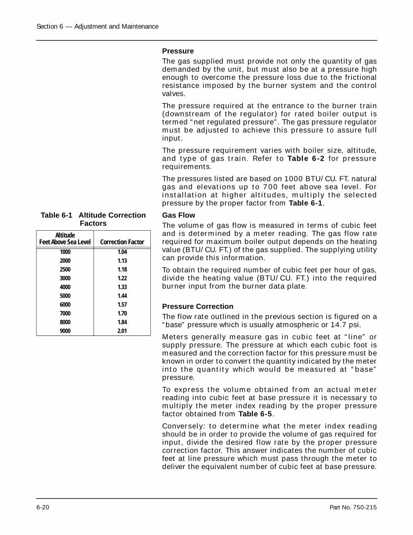
Section 6 — Adjustment and Maintenance
6-20 Part No. 750-215
PressureThe gas supplied must provide not only the quantity of gasdemanded by the unit, but must also be at a pressure highenough to overcome the pressure loss due to the frictionalresistance imposed by the burner system and the controlvalves.
The pressure required at the entrance to the burner train(downstream of the regulator) for rated boiler output istermed “net regulated pressure”. The gas pressure regulatormust be adjusted to achieve this pressure to assure fullinput.
The pressure requirement varies with boiler size, altitude,and type of gas train. Refer to Table 6-2 for pressurerequirements.
The pressures listed are based on 1000 BTU/CU. FT. naturalgas and elevations up to 700 feet above sea level. Forinstallation at higher altitudes, multiply the selectedpressure by the proper factor from Table 6-1.
Table 6-1 Altitude Correction Factors
Gas FlowThe volume of gas flow is measured in terms of cubic feetand is determined by a meter reading. The gas flow raterequired for maximum boiler output depends on the heatingvalue (BTU/CU. FT.) of the gas supplied. The supplying utilitycan provide this information.
To obtain the required number of cubic feet per hour of gas,divide the heating value (BTU/CU. FT.) into the requiredburner input from the burner data plate.
Pressure CorrectionThe flow rate outlined in the previous section is figured on a“base” pressure which is usually atmospheric or 14.7 psi.
Meters generally measure gas in cubic feet at “line” orsupply pressure. The pressure at which each cubic foot ismeasured and the correction factor for this pressure must beknown in order to convert the quantity indicated by the meterinto the quantity which would be measured at “base”pressure.
To express the volume obtained from an actual meterreading into cubic feet at base pressure it is necessary tomultiply the meter index reading by the proper pressurefactor obtained from Table 6-5.
Conversely: to determine what the meter index readingshould be in order to provide the volume of gas required forinput, divide the desired flow rate by the proper pressurecorrection factor. This answer indicates the number of cubicfeet at line pressure which must pass through the meter todeliver the equivalent number of cubic feet at base pressure.
AltitudeFeet Above Sea Level Correction Factor
1000 1.042000 1.132500 1.183000 1.224000 1.335000 1.446000 1.577000 1.708000 1.849000 2.01
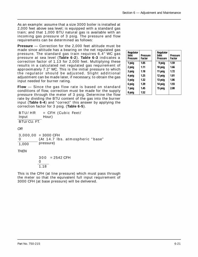
Section 6 — Adjustment and Maintenance
Part No. 750-215 6-21
As an example: assume that a size 3000 boiler is installed at2,000 feet above sea level; is equipped with a standard gastrain; and that 1,000 BTU natural gas is available with anincoming gas pressure of 3 psig. The pressure and flowrequirements can be determined as follows:
Pressure — Correction for the 2,000 feet altitude must bemade since altitude has a bearing on the net regulated gaspressure. The standard gas train requires 6.4" WC gaspressure at sea level (Table 6-2). Table 6-3 indicates acorrection factor of 1.13 for 2,000 feet. Multiplying theseresults in a calculated net regulated gas requirement ofapproximately 7.2" WC. This is the initial pressure to whichthe regulator should be adjusted. Slight additionaladjustment can be made later, if necessary, to obtain the gasinput needed for burner rating.
Flow — Since the gas flow rate is based on standardconditions of flow, correction must be made for the supplypressure through the meter of 3 psig. Determine the flowrate by dividing the BTU content of the gas into the burnerinput (Table 6-4) and “correct” this answer by applying thecorrection factor for 3 psig. (Table 6-5).
OR
THEN
This is the CFH (at line pressure) which must pass throughthe meter so that the equivalent full input requirement of3000 CFH (at base pressure) will be delivered.
Regulator InletPressure
PressureFactor
Regulator InletPressure
PressureFactor
1 psig 1.05 9 psig 1.592 psig 1.11 10 psig 1.663 psig 1.18 11 psig 1.724 psig 1.25 12 psig 1.815 psig 1.32 13 psig 1.866 psig 1.39 14 psig 1.937 psig 1.45 15 psig 2.008 psig 1.52
BTU/HRInput
= CFH (Cubic Feet/Hour)
BTU/CU. FT.
3,000,000
= 3000 CFH (At 14.7 lbs. atmospheric “base”pressure)1,000
3000
= 2542 CFH
1.18
Section 6 — Adjustment and Maintenance
6-22 Part No. 750-215
Checking Gas FlowYour gas supplier can generally furnish a chart developed todetermine the cubic feet/hour reading from the meter basedon the number of seconds per revolution of the 10 cubic feetdial. This provides a knowledge of the flow rate after arelatively short observation period.
Lacking a chart of this nature it is possible to “clock the gasmeter” as follows:
1. Turn off all other gas appliances that may be served by the meter.
2. Set burner at high fire.
3. Note meter reading and record consumption for 3 minutes.
4. The following formula will provide the required gas input for a 3 minute period:
Input (BTU/HR) ÷ Heating Value (BTU/CU. FT.) ÷ 20 = Gas input in cubic feet for 3 minutes.
5. Apply any necessary pressure correction factor to this answer to obtain the desired rate.
6. To illustrate, using circumstances from previous example, compute as follows:
BTU/HR ÷ BTU/CU. FT. ÷ 20 = 3 minute input in cu. ft.
OR
3,000,000 ÷ 1000 ÷ 20 = 150 cu. ft. (base pressure)
150 ÷ 1.18 (pressure correction = 127 cu. ft. (line pressure)
7. If the input timed for 3 minutes does not agree with the rating indicated by the formula, adjust the gas pressure regulator to increase or decrease flow as required.
Note: The information given in this section is for all practicalpurposes sufficient to set and adjust controls for gasinput. Your gas supplier can if necessary furnish exactcorrection factors that take into consideration BTUcontent, exact base pressure, specific gravity,temperature, etc., of the gas used.
4. Combustion Adjustment — GasGas input adjustment is accomplished by increasing ordecreasing the pressure of gas downstream of the pressureregulator. Any required adjustment to the regulator shouldbe done with burner at high fire and with the gas butterflyvalve wide open.
In the event linkage or regulator adjustments are required,proceed as follows. Initially set the linkage by backing outthe low fire stop screw so the valve is closed. Then turn screw
Section 6 — Adjustment and Maintenance
Part No. 750-215 6-23
in two complete turns. Adjust the connecting rod so thattension is released.
It is not practical to list specific setting of the connectionpoints or of the angles of the arms. The final setting shouldprovide a coordinated movement of the damper and the gasvalve. If the gas valve opens rapidly compared to the airdamper, an overly rich fire will occur during transitionbetween the two firing positions. This improper fuel-air ratiocan cause sooting of the fireside surfaces. If it opens tooslowly then the propor tionally greater air f low couldextinguish the flame.
Points to remember are that the motor arm must completeits full travel and that the valve arm should travel its requiredarc without excessive stretching of the override springs. Thecloser that the swivel joint in the motor arm is to the hub, theless distance it will travel. To increase the valve arm travel,move the connecting rod closer to the hub or away from it ifdecreased travel is required.
This low fire setting should be regarded as tentative untilproper gas pressure for high fire operation is established.
After operating at low fire for a sufficient period of time toassure a warm boiler, turn the damper positioning switch to“high”. Observe the burner as it progresses toward high fire.In the event gas pressure is too low or if the butterfly valvemovement is not properly coordinated with the air damper,it is possible that increased air flow may extinguish the flame.Immediately turn burner off. Determine and correctcondition causing flame failure before repeating attempt.
At high-fire position, the butterfly valve should be wide openas indicated by the slot on the end of its shaft. Set and lockthe high fire stop screw until it is just touching the valve arm.
Determine the actual gas flow from a meter reading asoutlined in another section. If corrections are necessary toobtain the required input, increase or decrease the gaspressure by adjusting the pressure regulator. Turn itsadjusting screw clockwise to increase pressure, orcounterclockwise to decrease pressure.
When the high fire gas flow is established, no furtheradjustment of the regulator is required.
With proper gas flow, any further adjustment necessary toobtain a desirable flue gas analysis must be done with theair damper. Check all adjustments with a combustion gasanalyzer.
When the high fire air fuel ratio is set, shut the burner down,relight and check low fire. It may be necessary to readjustthe low fire stop screw or the linkage. To assure that low-fireposition of the butterfly valve is always the same, allow aminimum of one turn of the stop screw for over-travel.
Section 6 — Adjustment and Maintenance
6-24 Part No. 750-215
Any adjustment must not cause extensive stretching of theoverride springs. If linkage adjustments are made, recheckto determine that high fire is not affected.
The appearance or color of the gas flame is not an indicationof its efficiency since an efficient gas flame will vary fromtransparent blue to translucent yellow.
Proper setting of the air/fuel ratios at all rates of firing mustbe established by the use of a combustion gas analyzer. Thisinstrument measures the content, by percentage, of carbondioxide (CO2), oxygen (O2), and carbon monoxide (CO) in theflue gas.
Burner efficiency is measured by the amount or percentageof CO2 present in the flue gas. The theoretical maximum CO2percentage for natural gas is approximately 11.7%. This isattained when there is no excess oxygen (O2) or carbonmonoxide (CO). A definite percentage of excess air (oxygen)is required by most local gas authorities and, of course, theburner should never be operated with an air-fuel ratio thatindicates a detectable percentage of carbon monoxide.
Subject to local regulations pertaining to specific amounts ofexcess oxygen, it is generally recommended that CO2readings of between 9-1/2 and 10-1/2% be attained withcorresponding 02 readings of 2 to 4%.
Water washing of the fireside surfaces of a gas fired boiler isusually not required. Washing lances are not providedalthough a gas burning boiler — Series 700 — does haveprovisions for their addition. If stack temperatures indicatea need for washing, lances can be ordered from your agent.However, a condition of this nature would indicate a definitemaladjustment of the burner that requires attention andcorrection.
H.DAMPER MOTOR AND AUXILIARY SWITCHES
The damper motor, in addition to controlling the damper(and the gas valve linkage) contains one, or two, internalswitches which serve as a Low Fire Switch and, if required, aHigh Fire Switch. These switches are actuated by camsattached to the shaft of the motor. They are factory set andshould not normally require any adjustment.
If adjustment is required to the internal switches, loosen thelocking screw on the cam assembly about one half turn. Donot remove the cam assembly.
With the motor in its fully closed position, rotate the camcounterclockwise until the switch makes an “audible click”.Adjust the cam so that the slow-rise portion of the lobeengauges the switch lever to operate the switch. This gives aswitching differential of approximately 10°.
Section 6 — Adjustment and Maintenance
Part No. 750-215 6-25
The Low Fire Switch (LFS) used on all boilers must be closedto complete programmer circuitry that assures that thedamper is in the low-fire position before ignition takes place.The switch opens when the damper motor drives to openduring pre-purge and closes when it returns to low-fireposition on completion of pre-purge. The switch, therefore,must be actuated just prior to the damper reaching itsclosed position.
The High Fire Switch (HFS), when required, is used to provethat the air damper opens during the pre-purge. Its terminalsshould make when the damper is nearly open and just beforethe timing of the programmer returns the motor to low-fireposition.
Oil Valve SwitchesAttached to the damper motor is an auxiliary controlcontaining two switches. See Figure 6-3.
The first switch (left hand side) is used for the intermediateoil valve. The right hand switch is used for the high fire oilvalve.
The following directions are based on adjusting the switchprior to its attachment to the damper. While particularlyuseful during replacement, they will also serve as a guide forfinal adjustment.
1. BEFORE attaching the switch to the mounting bracket, depress the scale lock and rotate the scale so that the zero mark of the outer scale on the silver scale is at the index mark.
2. Release the scale lock. Remove the thumb nut and the top set of cams.
3. Loosen both cam locking screws on the remaining set of cams. Align the two cam lobes so that only the operational cam (silver colored) will cause switch lever movement. Tighten the differential cam screw.
4. The switching action desired is for the normally open leads (red and blue) to close as the motor travels from low to high fire. Using the index mark as a reference point, push the scale lock down and turn the scale counterclockwise approximately 10° (motor stroke is 90°). Release the scale lock.
5. Turn cam until the cam roller of the switch lever is exactly over the outer corner of the operational cam lobe. A slight movement of the cam at this point should produce an audible click in the switch. Tighten the operational cam’s locking screw.
6. No cam differential is desired between the make and the break of the contacts, so be sure that the differential cam lobe (brass colored) and the operational cam lobe are
Section 6 — Adjustment and Maintenance
6-26 Part No. 750-215
aligned so that the differential cam has no effect on the switch.
7. Place the second set of cams on the shaft. Make sure that the operational cam’s locking screw is on the opposite side of the shaft of the switch the cam is to operate (when the scale plate is set at zero).
8. Adjust the cam lobes as described in step 3.
9. Depress the scale lock. Turn the cam so that the cam roller of the No. 2 switch lever is exactly over the outer corner of the operational cam lobe when the scale indicates 60°. Replace and tighten thumb screw.
10. Connect the red and blue leads to the oil valve circuit as shown on the wiring diagram. The yellow lead is not required and its end should be insulated to prevent short circuits.
11. Check the operation of the switches under actual operating conditions. Make any necessary cam adjustments to insure that the oil valves open at the desired point.
The variables involved may require adjustment of the camsunder operating conditions. The point of valve actuation isdirectly related to the amount of damper travel on aparticular burner. The first switch should be actuated toclose midway between low and high fire. This causes theintermediate oil valve to open and the second nozzle to fire,providing an increased firing rate for a smoother changeoverbetween the low and high fire rates and vice versa. As the airdamper moves towards the high-fire position, an increasingamount of air is allowed into the boiler. The valve shouldopen in approximately mid range of the air input butdefinitely at a point where sufficient air is present so thatthere is no incomplete combustion or smoke. The positioningof the cam must be guided while observing the fire or stackwhen the valve opens. If smoke or haze is noticed, repositioncam to slightly retard valve opening.
The second oil valve switch should be actuated just as thedamper reaches its open position. Based upon a combustionanalysis, a damper position linkage adjustment may berequired to provide more or less air at this point.
I. AIR DAMPER ADJUSTMENTThe arms and connecting rod that transmit motion from thedamper motor to the air damper (and to the gas butterflyvalve on a gas fired unit) are set at the factory and should notnormally need further adjustment.
If adjustments are required, or to aid in determining theposition of linkage in event of replacement, the followingfactors should serve as guides.
Section 6 — Adjustment and Maintenance
Part No. 750-215 6-27
1. The damper motor should be able to complete its full travel range of 90 degrees. A restriction can cause damage.
2. Initial adjustment is done with the motor in its closed or unpowered condition. The power end of the shaft will be in its most counterclockwise position.
3. Secure the motor arm approximately 60 degrees below the horizontal centerline.
4. The slot on the end of the damper shaft indicates the position of the damper blade.
5. It is not practical to list specific setting of all of the connections or of the damper arm angle, since adjustment conditions must exist to meet combustion requirements or load conditions.
6. The closer the swivel joint in the motor arm is to the hub, the less distance it will travel.
7. The amount of damper opening increases when its connecting joint is closer to the hub. To decrease opening, move the ball joint away from the hub.
8. Final adjustments should result in a coordinated movement of the damper and damper motor.
Normally, at low fire the damper blade is cracked slightlyopen. With the burner firing at its low rate, hold the dampershaft securely with pliers and loosen the setscrew on its arm.Manually close damper until a slight haze appears and thenopen until it clears. Tighten setscrews and for referencepurposes mark the position of the shaft slot to indicateapproximate low fire damper setting.
Turn the damper positioning switch to “high” and observethe burner as it progresses to high fire, to be sure that airflow is coordinated with fuel flow.
Too much air can extinguish the flame and damper travelmust be regulated accordingly. When high-fire position isreached again observe the flame appearance. If it is hazythen more air is required. Determine approximate setting byfollowing the procedure outlined in the previous paragraphto obtain a haze-free fire. Again, make a reference markshowing the open position.
Note: As pointed out in the sections pertaining to combustionadjustment, color is a poor indication of flameefficiency and should be used only for tentativeadjustment. Final adjustments should be made basedupon stack analysis and with proper fuel input.
With the limits of low fire and high fire damper traveldetermined from reference marks, adjustment can now bemade to the connecting rod connections.
Section 6 — Adjustment and Maintenance
6-28 Part No. 750-215
Periodically check for proper adjustment. Check tightness ofsetscrews to prevent slippage. Occasionally oil swivel jointswith a graphite or silicone type lubricant.
J. SAFETY VALVESThe safety valve is a very important safety device anddeserves attention accordingly.
The purpose of the valve(s) is to prevent pressure buildupover the design pressure of the pressure vessel. The size,rating and number of valves on a boiler is determined by theASME Boiler Code. The installation of a valve is of primaryimportance to its service life. A valve must be mounted in avertical position so that discharge piping and Code requireddrains can be properly piped to prevent buildup of backpressure and accumulation of foreign material around thevalve seat area. Apply only a moderate amount of pipecompound to male threads and avoid overtightening as thiscan distort the seats. Use only flat jawed wrenches on theflats provided. When installing a flange connected valve, usea new gasket and draw the mounting bolts down evenly. Donot install or remove side outlet valves by using a pipe orwrench in the outlet.
A drip pan elbow or a flexible connection between the valveand the escape pipe is recommended. The discharge pipingmust be properly arranged and supported so that its weightdoes not bear upon the valve.
Do not paint, oil, or otherwise cover any interior or workingparts of the safety valve. A valve does not require anylubrication or protective coating to work properly.
Follow the recommendations of your boiler inspectorregarding valve inspection and testing. The frequency oftesting, either by the use of the lifting lever or by raising thesteam pressure, should be based on the recommendation ofyour boiler inspector, and/or the valve manufacturer, and inaccordance with Sections VI and VII of the ASME Boiler andPressure Vessel Code.
Avoid excessive operation of the safety valve as even oneopening can provide a means of leakage. Safety valvesshould be operated only often enough to assure that they arein good working order. When a pop test is required, raise theoperating pressure to the set pressure of the safety valve,allowing it to open and reseat as it would in normal service.
Do not hand operate the valve with less than 75% of thestamped set pressure exerted on the underside of the disc.When hand operating, be sure and hold the valve in an openposition long enough to purge accumulated foreign materialfrom the seat area and then allow the valve to snap shut.
Frequent usage of the safety valve will cause the seat anddisc to become wire drawn or steam cut. This will cause thevalve to leak and necessitate downtime of the boiler for valve
Section 6 — Adjustment and Maintenance
Part No. 750-215 6-29
repair or replacement. Repair of a valve must be done onlyby the manufacturer or his authorized representative.
Avoid having the operating pressure too near the safety valveset pressure. A 10% differential is recommended. An evengreater differential is desirable and will assure better seattightness and valve longevity.
Steam is expensive to generate and, for the sake of economy,wastage should be avoided whenever possible.
The above comments, although written primarily for a safetyvalve on a steam boiler, are largely applicable to a relief valveon a hot water boiler. It is imperative that the dischargepiping be properly supported to avoid valve distortion andthat this piping is directed to a safe point of discharge.
K.MOTORIZED GAS VALVEShould the valve fail to operate, check its operation byapplying test leads of the proper voltage to terminals 1 and2 of the actuator. Make certain that the main shutoff cock isclosed prior to testing. If the actuator falls to operate, it mustbe replaced. The actuator is not field repairable nor shouldit be disassembled.
To remove the actuator, loosen the two 5/32" allen setscrewsthat hold the actuator collar to the valve bonnet.
After replacement, cycle the valve with the fuel shutoff todetermine that it opens and closes. If the valve has a visualindicator, observe the colored indicator: yellow — shut; red— open.
The auxiliary switch normally used as a valve closedindication switch is replaceable as a component.
Section 6 — Adjustment and Maintenance
6-30 Part No. 750-215
L. SOLENOID VALVES: GAS PILOT/FUEL OIL/VENT VALVES
Foreign matter between the valve seat and seat disc cancause leakage. Valves are readily disassembled, however,care must be used during disassembly to be sure thatinternal parts are not damaged during the removal and thatreassembly is in proper order.
A low hum or buzzing will normally be audible when coil isenergized. If valve develops loud buzzing or a chatteringnoise check for proper voltage and clean plunger assemblyand interior plunger tube thoroughly. Do not use any oil.Make sure that plunger tube and solenoid are tight whenreassembled. Take care not to nick, dent or damage theplunger tube.
Coils may be replaced without removing the valve from theline. Be sure to turn off power to the valve. Check coilposition and make sure that any insulating washers orretaining springs are reinstalled in proper order.
M.REFRACTORYThe Model 4 Boiler is shipped with completely installedrefractory. This consists of the burner tile, access door arida bed covering the lower drum.
The refractory should be checked for evidence of shippingdamage and repairs made prior to initial firing.
Periodic inspection will keep the operator informed of thecondition of refractory. Normal maintenance requires littletime and expense and prolongs operating life. Frequentwashcoating of al l surfaces is recommended. Hightemperature, air-dry type mortar diluted with water to theconsistency of light cream is used for this purpose. Coatingintervals will vary with service and are best determined byinspection.
Face all joints or cracks by applying mortar with a trowel orfinger tip. Do this as soon as cracks are detected. It isnormal for refractories exposed to hot gases to develop thin“hairl ine” cracks. This is caused by expansion andcontraction. Cracks up to 1/8 inch across may be expectedto close at high temperatures. If there are any that arerelatively large (1/8 to 1/4 inch) clean them and fill with hightemperature bonding mortar.
Refractory, under normal condit ions, wi l l last forconsiderable periods before replacement is necessary.
In the event of spalling of the furnace floor, remove affectedarea and replace with a mix made from regular Furnas-Crete(Kaiser).
The burner tile are precast special shapes, and replacementscan be ordered from your Cleaver-Brooks representative.Installation is generally done by working from inside of
Section 6 — Adjustment and Maintenance
Part No. 750-215 6-31
furnace and through the access door. Dry fit all the segmentsand chip to fit, if necessary. Reinstall, using properrefractory cement. Make sure that all joints are tight andcoated with cement. Mix insulating cement with refractorymortar and work the mixture into the crevices formed by theback of the tile and the boiler tube panel. It is important thata good tight seal be attained between the burner housingand the brick. Make sure that the insulating material is inplace and cement all joints and crevices. Periodically checkthe seal and repack as required.
N.FUEL CHANGEOVER MAINTENANCEA boiler that is equipped to burn either oil or gas is often runfor extended periods on either one of these fuels. To insurethat the alternate fuel system is in working order, it issuggested that the burner be changed over for a short run ona periodic basis such as monthly. This prevent ivemaintenance will permit checking of fuel valves and controlsto determine their standby readiness. Circulation of oilthrough the system on a unit primarily firing gas is beneficialto the pump.
O.FORCED DRAFT FANRotation of the fan is counterclockwise when viewed fromfront of burner. If motor is ever replaced be sure that rotationis proper when motor leads are reconnected. Remove the oilpump belt before testing for motor rotation. Occasionallycheck to see that fan is securely tightened on motor shaft. Aretaining washer on the end of motor shaft holds the fan inthe proper position and there should be no rubbing orcontact with the air inlet. If the boiler is installed in a dustylocation check the vanes for deposits of dust or dirt; buildupof such deposits can cause a decrease in air capacity or leadto an unbalanced fan condition.
P. FURNACE ACCESS AND FIRESIDE CLEANING
The entire windbox is attached to a davit and can be swungaside from the boiler. A bolted panel is provided for furnaceinspection or access.
To swing front head:
1. Remove access casing panels and insulation on both sides of boiler.
Disconnect the fuel l ines at unions or other pipingconnections
Section 6 — Adjustment and Maintenance
6-32 Part No. 750-215
.
2. Disconnect the sight tube cooling line.
3. Disconnect pressure control lines on a steam boiler. Remove the remote bulbs from the water controls on a hot water boiler.
4. Unbolt the windbox from the burner flange.
5. Swing the windbox assembly on its davit
.
6. Remove bolting from access panel.
Reassemble in reverse order. Check the condition of the gasketing on theaccess panel and on the burner flange and replace if necessary. Restorethe fuel supply and check the tightness of all reconnected piping.
Before firing, remove the burner drawer and reseal the burner housing.See Section of this chapter.
Refer to appropriate sections in Chapter 2 for information on cleaningof fireside and waterside boiler surfaces. Lubrication
Electric MotorsManufacturers of electric motors vary in their specifications forlubrication and care of motor bearings and their recommendationsshould be followed.
Ball bearing equipped motors are pre-lubricated. The length of time abearing can run without having grease added or the bearing replaced,will depend upon many factors. The rating of the motor, type of motorenclosure, duty, atmospheric conditions, humidity, and ambienttemperatures are but a few of the factors involved.
Complete renewal of grease can, on some motors, be accomplished byforcing out the old grease with the new. Thoroughly wipe those portionsof the housing around the filler and drain plugs (above and belowbearings). Remove the drain plug (bottom) and free the drain hole of anyhardened grease which may have accumulated. With the motor notrunning, add new grease through the filler hole until clear grease startsto come out of the drain hole. Before replacing the drain plug run themotor for 10 to 20 minutes to expel any excess grease. The filler anddrain plugs should be thoroughly cleaned before they are replaced.
! CautionMake certain that fuel supply —oil and/or gas — is properly shutoff prior to disconnecting.
! CautionCheck for interference for fieldinstalled wiring or piping.
Section 6 — Adjustment and Maintenance
Part No. 750-215 6-33
The lubricant used should be clean and equal to one of the goodcommercial grades of grease locally available. Some lubricants that aredistributed nationally are:
Control LinkageApply a non-gumming dripless high temperature lubricant, such asgraphite or a silicone derivative to all pivot points and moving parts.Work lubricant in well and wipe excess. Repeat application at requiredintervals to maintain freedom of motion of parts.
Solenoid valves and motorized valves require no lubrication.BurnerHousing Seal
The area between the end of the burner housing and the refractoryfacing of the oven must be properly sealed to avoid damage. Thecondition of this seal must be checked prior to placing the boiler intoinitial operation and periodically thereafter. Whenever the front head isswung aside, it will be necessary to reseal this area.
Resealing can be accomplished by using a half and half mixture ofinsulating pulp and refractory cement. Remove the burner drawer andclean away as much of the old seal as possible. Force the sealing mixturearound the outer perimeter of the burner housing using care to makesure that the holes in the gas housing are not obstructed. The use of amirror can be helpful in making a proper seal.
Gulf Oil – Precision GreaseNo. 2
Humble Oil – Andok BTexaco – Multifak No. 2Phillips – 1 B + RB No. 2Fiske Bros. – Ba l l Bear ing
LubriplateS tandard/Mobile
– Mobilux No. 2
Section 6 — Adjustment and Maintenance
6-34 Part No. 750-215
Notes:
Milwaukee, Wisconsin
www.cleaver-brooks.com
Section 7Troubleshooting
A. Burner Does Not Start . . . . . . . . . . . . . . . . . . . . . . . . . . . . . . . . . . . . 7-2B. No Ignition . . . . . . . . . . . . . . . . . . . . . . . . . . . . . . . . . . . . . . . . . . . . . 7-3C. Pilot Flame, But No Main Flame . . . . . . . . . . . . . . . . . . . . . . . . . . . 7-4D. Burner Stays in Low Fire . . . . . . . . . . . . . . . . . . . . . . . . . . . . . . . . . 7-4E. Shutdown Occurs During Firing . . . . . . . . . . . . . . . . . . . . . . . . . . . . 7-5F. Damper Motor Does Not Operate . . . . . . . . . . . . . . . . . . . . . . . . . . . 7-6
Section 7 — Troubleshooting
7-2 Part No. 750-215
This section assumes that the unit has been properlyinstalled and adjusted and that it has been running for sometime prior to the trouble listed in the heading of eachsection. It is further assumed that the operator has becomethoroughly familiar with both burner and manual by thistime. The points under each heading are set down briefly aspossible causes, suggestions or clues to simplify locatingthe source of trouble. Methods of correcting the trouble,once it has been identified, may be found elsewhere in thismanual.
If the burner will not start, or operate properly, refer to thistroubleshooting section and to the programming relaybulletin for assistance in pinpointing problems that may notbe readily apparent. Familiarity with the programmer andother controls in the system may be obtained by studying thecontents of this manual and the bulletin. Knowledge of thesystem and its controls will make troubleshooting mucheasier. Costly downtime or delays can be prevented bysystematic checks of the actual operation against thenormal sequence to determine the stage at whichperformance deviates from normal. Following a routine maypossibly eliminate overlooking an obvious condition, oftenone that is relatively simple to correct.
If an obvious condition is not apparent, check the continuityof the circuits with a voltmeter or test lamp. Each circuit canbe checked and the fault isolated and corrected. Mostcircuitry checking can be done between appropriateterminals on the terminal boards in the control cabinet orthe entrance box. Refer to the schematic Wiring Diagram forterminal identification.
A.BURNER DOES NOT START 1. Main disconnect switch open.
2. Blown fuses, tripped overload, loose electrical connections.
3. Combustion control safety switch requires resetting.
A. Refer to instructions supplied with program relay(combustion control).
B. Check for 120 V power input to the program relay(combustion control).
C. Check for power to the blower motor).
D. Check that appropriate relay contacts are closed (seeprogrammer bulletin).
4. Limit circuit not completed
A. Pressure or temperature is above setting of operating control.
B. Water below required level
1). Low water light, if provided, should indicate thiscondition.
Section 7 — Troubleshooting
Part No. 750-215 7-3
2). Check manual reset button, if provided, on low watercontrol.
C. Fuel pressure must be within settings of low pressure andhigh pressure switches.
5. Motor defective
6. If burner starts, but shuts down after a few seconds, check the air proving switch circuit.
B. No Ignition1. Lack of spark
A. Electrode grounded or porcelain cracked
B. Improper electrode setting
C. Loose terminal on ignition cable: cable shorted
D. Inoperative ignition transformer
E. Check appropriate program relay contacts.
2. Spark but no flame
A. Lack of fuel — no gas pressure, closed valve, empty tank,broken line, etc.
B. Inoperative pilot solenoid or low fire oil valve
C. Insufficient or no voltage to gas pilot solenoid valve.
3. Low fire switch open
A. Damper motor not closed, slipped cam, defective switch
B. Damper jammed or linkage binding
4. Check interlocks.
5. Timer switch in TEST position and timer stopped in “pre-purge”
Section 7 — Troubleshooting
7-4 Part No. 750-215
C. Pilot Flame, But No Main Flame1. Insufficient pilot flame
2. Gas fired unit:
A. Manual gas cock closed
B. Main gas valve inoperative
1). Low or high gas pressure (reset switch if necessary)
3. Oil fired unit:
A. Oil supply cut-off by obstruction, closed valve, or loss ofsuction
B. Pump inoperative; belt broken or slipping
C. No fuel
D. Inoperative solenoid valve
E. Check oil nozzles and lines.
4. Inoperative programmer
A. If appropriate relay does not pull in when pilot flame lights,check flame detector, contacts, amplifier.
B. Flame detector defective, sight tube obstructed or detectorlens dirty
C. Check for voltage to fuel valve when appropriate relatactivates.
D. Burner Stays in Low Fire1. Pressure or temperature above high-low fire control setting
2. Damper positioning switch in wrong position
3. Inoperative damper motor (See Section F)
4. Defective high-low fire control
5. Binding or loose linkage, cams, setscrews, etc.
6. Check appropriate relay contacts.
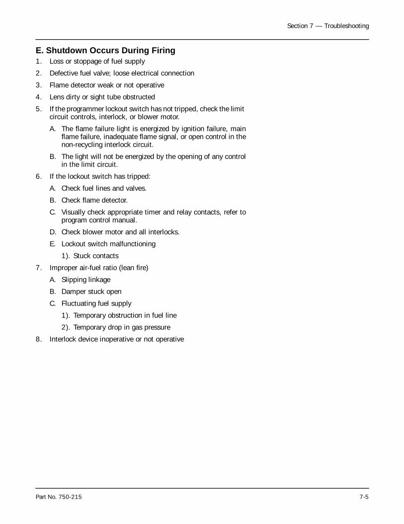
Section 7 — Troubleshooting
Part No. 750-215 7-5
E. Shutdown Occurs During Firing1. Loss or stoppage of fuel supply
2. Defective fuel valve; loose electrical connection
3. Flame detector weak or not operative
4. Lens dirty or sight tube obstructed
5. If the programmer lockout switch has not tripped, check the limit circuit controls, interlock, or blower motor.
A. The flame failure light is energized by ignition failure, mainflame failure, inadequate flame signal, or open control in thenon-recycling interlock circuit.
B. The light will not be energized by the opening of any controlin the limit circuit.
6. If the lockout switch has tripped:
A. Check fuel lines and valves.
B. Check flame detector.
C. Visually check appropriate timer and relay contacts, refer toprogram control manual.
D. Check blower motor and all interlocks.
E. Lockout switch malfunctioning
1). Stuck contacts
7. Improper air-fuel ratio (lean fire)
A. Slipping linkage
B. Damper stuck open
C. Fluctuating fuel supply
1). Temporary obstruction in fuel line
2). Temporary drop in gas pressure
8. Interlock device inoperative or not operative
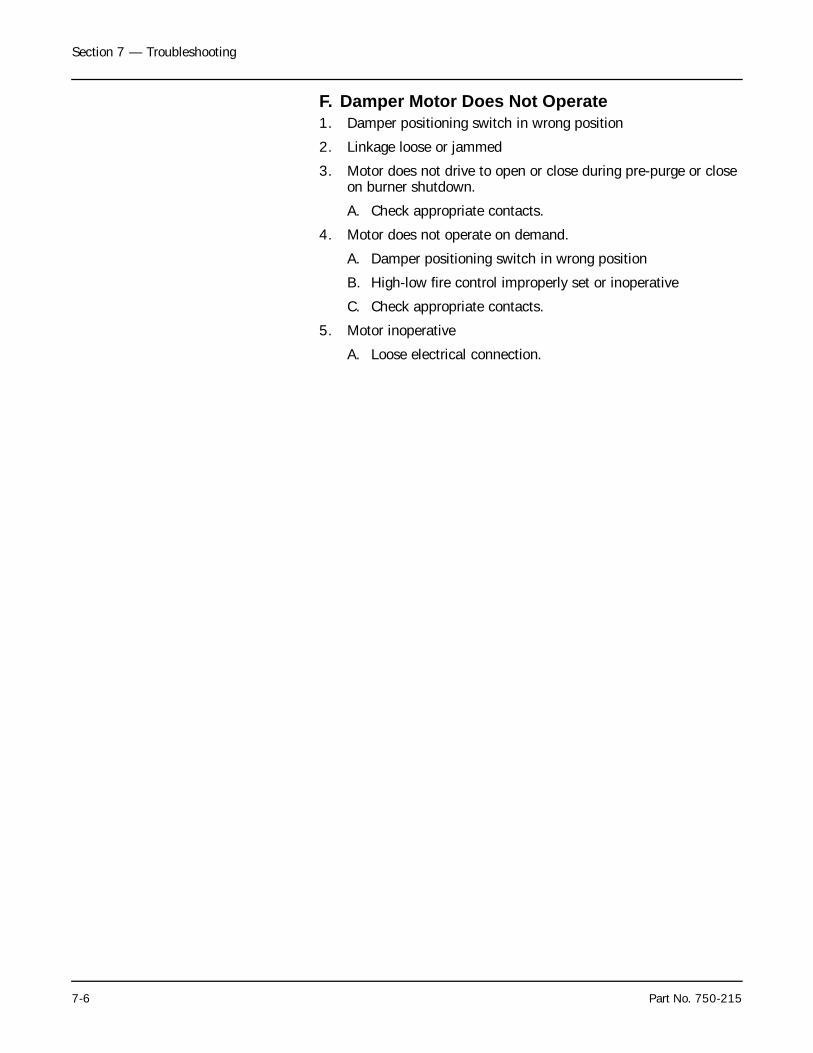
Section 7 — Troubleshooting
7-6 Part No. 750-215
F. Damper Motor Does Not Operate1. Damper positioning switch in wrong position
2. Linkage loose or jammed
3. Motor does not drive to open or close during pre-purge or close on burner shutdown.
A. Check appropriate contacts.
4. Motor does not operate on demand.
A. Damper positioning switch in wrong position
B. High-low fire control improperly set or inoperative
C. Check appropriate contacts.
5. Motor inoperative
A. Loose electrical connection.
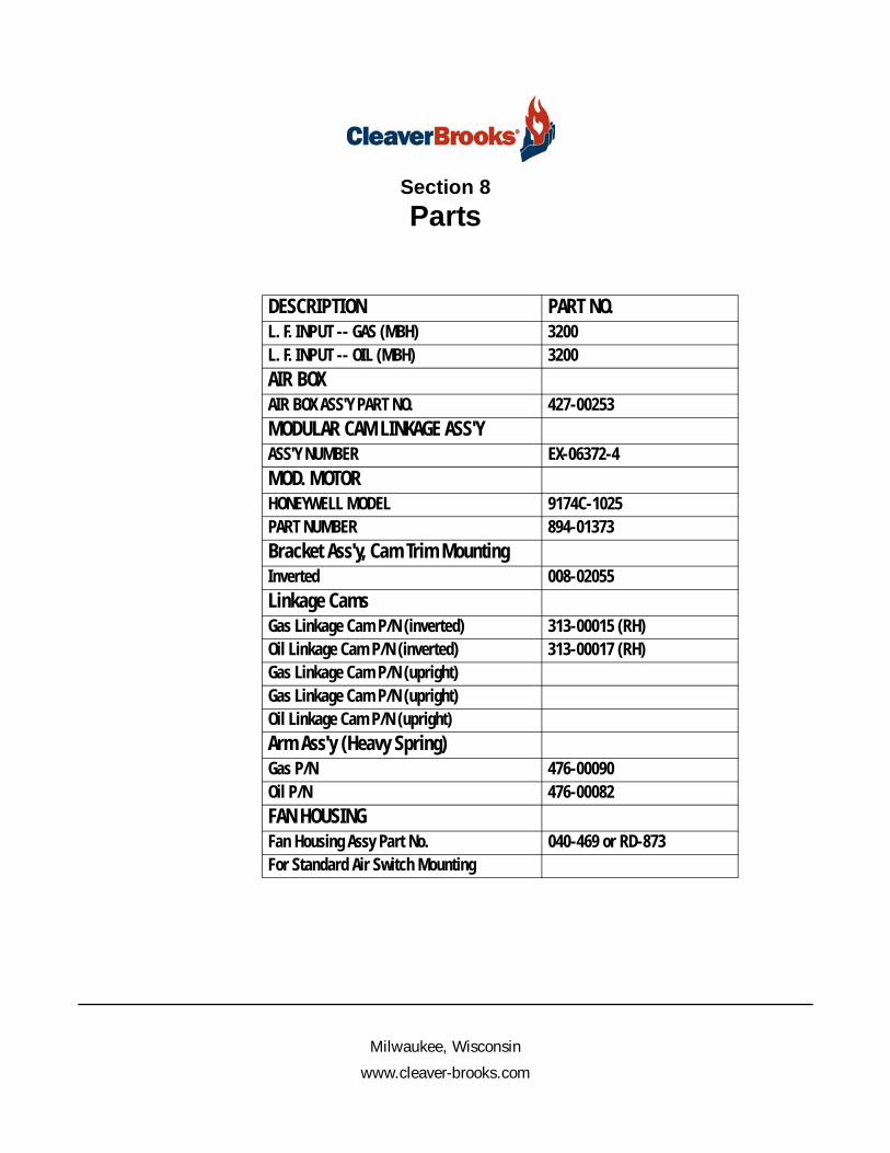
Milwaukee, Wisconsin
www.cleaver-brooks.com
Section 8Parts
DESCRIPTION PART NO.L. F. INPUT -- GAS (MBH) 3200L. F. INPUT -- OIL (MBH) 3200AIR BOXAIR BOX ASS'Y PART NO. 427-00253MODULAR CAM LINKAGE ASS'YASS'Y NUMBER EX-06372-4MOD. MOTORHONEYWELL MODEL 9174C-1025PART NUMBER 894-01373Bracket Ass'y, Cam Trim MountingInverted 008-02055Linkage CamsGas Linkage Cam P/N (inverted) 313-00015 (RH)Oil Linkage Cam P/N (inverted) 313-00017 (RH)Gas Linkage Cam P/N (upright)Gas Linkage Cam P/N (upright)Oil Linkage Cam P/N (upright)Arm Ass'y (Heavy Spring)Gas P/N 476-00090Oil P/N 476-00082FAN HOUSINGFan Housing Assy Part No. 040-469 or RD-873For Standard Air Switch Mounting
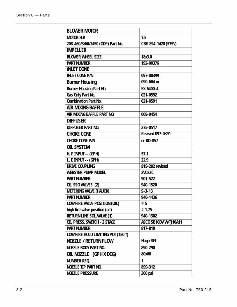
Section 8 — Parts
8-2 Part No. 750-215
BLOWER MOTORMOTOR H.P. 7.5208-460/3/60/3450 (ODP) Part No. CB#894-1420 (575V)IMPELLERBLOWER WHEEL SIZE 18x3.0PART NUMBER 192-00376INLET CONEINLET CONE P/N 097-00399Burner Housing 090-604 orBurner Housing Part No. EX-6400-4Gas Only Part No. 021-0592Combination Part No. 021-0591AIR MIXING BAFFLEAIR MIXING BAFFLE PART NO. 009-0454DIFFUSERDIFFUSER PART NO. 275-0517CHOKE CONE Revised 097-0391CHOKE CONE P/N or RD-857OIL SYSTEMH. F. INPUT -- (GPH) 57.1L. F. INPUT -- (GPH) 22.9DRIVE COUPLING 819-202 revisedWEBSTER PUMP MODEL 2V023CPART NUMBER 901-522OIL SSO VALVES (2) 940-1520METERING VALVE (HAUCK) S-3-13PART NUMBER 940-1436LOW FIRE VALVE POSITION (OIL) #5high fire valve position (oil) #1.75RETURN LINE SOL.VALVE (1) 940-1302OIL PRESS. SWITCH - 2 STAGE ASCO SB10DV W/TJ10A11PART NUMBER 817-810LOW FIRE HOLD LIMITING POT (150 ?)NOZZLE / RETURN FLOW Hago RFLNOZZLE BODY PART NO. 890-290OIL NOZZLE (GPH X DEG) 80x60NUMBER REQ. 1NOZZLE TIP PART NO. 899-312NOZZLE PRESSURE 300 psi
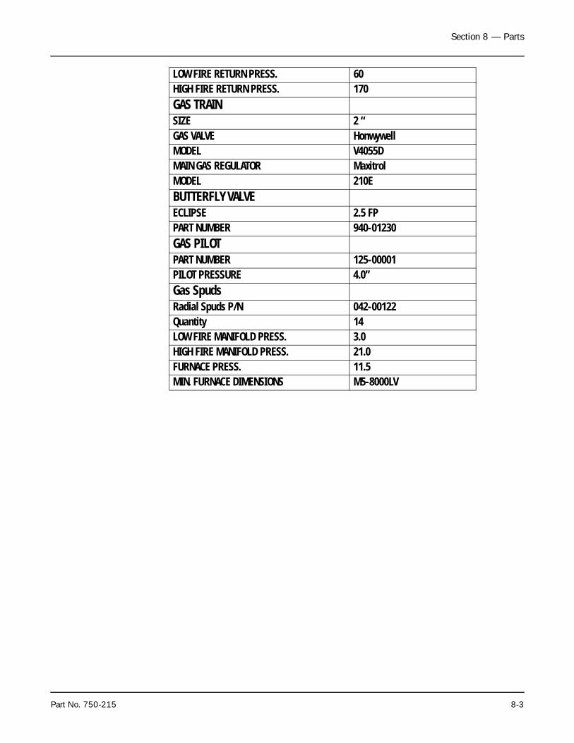
Section 8 — Parts
Part No. 750-215 8-3
LOW FIRE RETURN PRESS. 60HIGH FIRE RETURN PRESS. 170GAS TRAINSIZE 2 “GAS VALVE HonwywellMODEL V4055DMAIN GAS REGULATOR MaxitrolMODEL 210EBUTTERFLY VALVEECLIPSE 2.5 FPPART NUMBER 940-01230GAS PILOTPART NUMBER 125-00001PILOT PRESSURE 4.0”Gas SpudsRadial Spuds P/N 042-00122Quantity 14LOW FIRE MANIFOLD PRESS. 3.0HIGH FIRE MANIFOLD PRESS. 21.0FURNACE PRESS. 11.5MIN. FURNACE DIMENSIONS M5-8000LV

Section 8 — Parts
8-4 Part No. 750-215

NOTES

e-mail: [email protected] Address: http://www.cleaverbrooks.com