model 4010 installation, configuration, and programming
TRANSCRIPT

Model 4010 Radio Dispatch Console Installation and Programming
025-9227S

©Zetron, Inc. All rights reserved. This publication is protected by copyright; information in this document is subject to change without notice. Zetron and the Zetron logo are registered trademarks of Zetron, Inc. Other company names and product names may be the trademarks or registered trademarks of their respective owners. This publication may not be reproduced, translated, or altered, in whole or in part, without prior written consent from Zetron, Inc.
Software License
The Zetron software described in this manual is subject to the terms and conditions of Zetron's Software License Agreement, a copy of which is contained on the product distribution media or otherwise provided or presented to buyer. Installation and/or use of the Zetron software constitutes acceptance of Zetron's Software License Agreement.
Limited Warranty
Buyer assumes responsibility for the selection of the Products to achieve buyer's or its customer's intended results obtained from the Products. If buyer has provided Zetron with any requirements, specifications or drawings, or if Zetron provides buyer with such materials, such materials are provided solely for buyer's convenience and shall not be binding on Zetron unless agreed in writing by the President of Zetron. ZETRON DOES NOT WARRANT THAT THE PRODUCTS OR ITS CUSTOMER'S REQUIREMENTS OR SPECIFICATIONS OR THAT OPERATION OF THE PRODUCTS WILL BE UNINTERRUPTED OR ERROR FREE. SUBJECT TO THE LIMITATIONS SET FORTH BELOW, Zetron warrants that all Zetron Products and Zetron Accessories will be free from material defects in material and workmanship for one year from date of shipment (except where indicated otherwise in the Zetron Price Book). For buyer's convenience, Zetron may purchase and supply additional items manufactured by others. In these cases, although Zetron's warranty does not apply, buyer shall be the beneficiary of any applicable third party manufacturer's warranties, subject to the limitations therein. Zetron's warranty covers parts and Zetron factory labor. Buyer must provide written notice to Zetron within the warranty period of any defect. If the defect is not the result of improper or excessive use, or improper service, maintenance or installation, and if the Zetron Products or Zetron Accessories have not been otherwise damaged or modified after shipment, AS ZETRON'S SOLE AND EXCLUSIVE LIABILITY AND BUYER'S SOLE AND EXCLUSIVE REMEDY, Zetron shall either replace or repair the defective parts, replace the Zetron Products or Zetron Accessories or refund the purchase price, at Zetron's option, after return of such items by buyer to Zetron. Shipment shall be paid for by the buyer. No credit shall be allowed for work performed by the buyer. Zetron Products or Zetron Accessories which are not defective shall be returned at buyer's expense, and testing and handling expense shall be borne by buyer. Out-of-warranty repairs will be invoiced at the then - current Zetron hourly rate plus the cost of needed components. THE FOREGOING WARRANTY AND THE THIRD PARTY MANUFACTURER'S WARRANTIES, IF ANY, ARE IN LIEU OF ANY AND ALL OTHER WARRANTIES EXPRESSED, IMPLIED OR ARISING UNDER LAW, INCLUDING, BUT NOT LIMITED TO, THE IMPLIED WARRANTIES OF MERCHANTABILITY, NON-INFRINGEMENT AND FITNESS FOR A PARTICULAR PURPOSE.
Limitation of Liability
Zetron makes no representation with respect to the contents of this document and/or the contents, performance, and function of any accompanying software.ZETRON SHALL NOT UNDER ANY CIRCUMSTANCES BE LIABLE TO BUYER OR ANY THIRD PARTY FOR ANY INCIDENTAL, SPECIAL, CONSEQUENTIAL OR INDIRECT LOSS OR DAMAGE ARISING OUT OF OR CONNECTED WITH BUYER'S PURCHASE OR USE OF PRODUCTS OR SERVICES, INCLUDING WITHOUT LIMITATION, LOSS OF USE, LOSS OR ALTERATION OF DATA, DELAYS, LOST PROFITS OR SAVINGS, EVEN IF ZETRON HAS BEEN ADVISED OF THE POSSIBILITY OF SUCH DAMAGES AND EVEN IF THE LIMITED REMEDY ABOVE IS FOUND TO FAIL OF ITS ESSENTIAL PURPOSE. IN NO EVENT SHALL ZETRON'S LIABILITY (WHETHER FOR NEGLIGENCE OR OTHER TORT, IN CONTRACT OR OTHERWISE) EXCEED THE PRICE PAID TO ZETRON FOR THE PRODUCTS.IP networks by their nature are subject to a number of limitations, such as security, reliability, and performance. Anyone using non-dedicated IP networks, such as shared WANs or the Internet, to connect to any Zetron Products or systems should consider and is responsible for these limitations.

3
Compliance Statements
This equipment has been tested and found to comply with the limits for a Class A digital device, pursuant to Part 15 of the FCC Rules. These limits are designed to provide reasonable protection against harmful interference when the equipment is operated in a commercial environment. This equipment generates, uses, and can radiate radio frequency energy and, if not installed and used in accordance with the instruction manual, may cause harmful interference to radio communications. Operation of this equipment in a residential area is likely to cause harmful interference in which case the user will be required to correct the interference at his own expense.This equipment meets the applicable Industry Canada Terminal Equipment Technical Specifications. This is confirmed by the registration number. The abbreviation, IC, before the registration number signifies that registration was performed based on a Declaration of Conformity indicating that Industry Canada technical specifications were met. It does not imply that Industry Canada approved the equipment.The Ringer Equivalence Number (REN) for this terminal equipment is 0.1. The REN assigned to each terminal equipment provides an indication of the maximum number of terminals allowed to be connected to a telephone interface. The termination on an interface may consist of any combination of devices subject only to the requirement that the sum of the RENs of all the devices does not exceed 5.0.
Safety Summary
• Follow all warnings and instructions marked on the equipment or included in documentation.• Only technically qualified service personnel are permitted to install or service the equipment.• Be aware of and avoid contact with areas subject to high voltage or amperage. Because some components can store
dangerous charges even after power is disconnected, always discharge components before touching.• Never insert objects of any kind through openings in the equipment. Conductive foreign objects could produce a short
circuit that could cause fire, electrical shock, or equipment damage.• Remove rings, watches, and other metallic objects from your body before opening equipment. These could be
electrical shock or burn hazards.• Ensure that a proper electrostatic discharge device is used, to prevent damage to electronic components.• Do not attempt internal service of equipment unless another person, capable of rendering aid and resuscitation, is
present.• Do not work near rotating fans unless absolutely necessary. Exercise caution to prevent fans from taking in foreign
objects, including hair, clothing, and loose objects.• Use care when moving equipment, especially rack-mounted modules, which could become unstable. Certain items
may be heavy. Use proper care when lifting.
Warning! For your safety and the protection of the equipment, observe these precautions when installing or servicing Zetron equipment:
Information on Disposal of Old Electrical and Electronic Equipment and Batteries (applicable for EU countries that have adopted separate waste collection systems)
Products and batteries with the symbol (crossed-out wheeled bin) cannot be disposed as household waste. Old electrical and electronic equipment and batteries should be recycled at a facility capable of handling these items and their waste byproducts.
Contact your local authority for details in locating a recycle facility nearest to you.
Proper recycling and waste disposal will help conserve resources whilst preventing detrimental effects on our health and the environment.
Notice: The sign “Pb” below the symbol for batteries indicates that this battery contains lead.
STOP

4 025-9227S
Change List for Rev S, 7 March 2011
• Added caution about silkscreen labels in Dual Channel Card Jumpers and Switches on page 27.• Corrected the channels associated with J2, J3, and J4 in Model 4010 Main Control Board on
page 104.• Added to the description of Instant Call on page 127.• Updated JP6-B description in Configuration on page 51.• Removed Entering IDs in Ericsson/GE MDX Radio.

Contents
5
Contents
Introduction. . . . . . . . . . . . . . . . . . . . . . . . . . . . . . . . . . . . . . . . . . . . . . . . . . . . . . . 9Manuals . . . . . . . . . . . . . . . . . . . . . . . . . . . . . . . . . . . . . . . . . . . . . . . . . . . . . . . . . . . . . . . . . . . . 11Specifications . . . . . . . . . . . . . . . . . . . . . . . . . . . . . . . . . . . . . . . . . . . . . . . . . . . . . . . . . . . . . . . . 12
Transmit Electrical Specifications . . . . . . . . . . . . . . . . . . . . . . . . . . . . . . . . . . . . . . . . . . . . . 12Receive Electrical Specifications . . . . . . . . . . . . . . . . . . . . . . . . . . . . . . . . . . . . . . . . . . . . . . 12Other Electrical Specifications . . . . . . . . . . . . . . . . . . . . . . . . . . . . . . . . . . . . . . . . . . . . . . . . 12Console Power Requirements . . . . . . . . . . . . . . . . . . . . . . . . . . . . . . . . . . . . . . . . . . . . . . . 13Power Supply (802-0092) Specifications . . . . . . . . . . . . . . . . . . . . . . . . . . . . . . . . . . . . . . . 13Physical Specifications . . . . . . . . . . . . . . . . . . . . . . . . . . . . . . . . . . . . . . . . . . . . . . . . . . . . . 13
Overview . . . . . . . . . . . . . . . . . . . . . . . . . . . . . . . . . . . . . . . . . . . . . . . . . . . . . . . . . . . . . . . . . . . 14System Description . . . . . . . . . . . . . . . . . . . . . . . . . . . . . . . . . . . . . . . . . . . . . . . . . . . . . . . . 14Installation Sequence. . . . . . . . . . . . . . . . . . . . . . . . . . . . . . . . . . . . . . . . . . . . . . . . . . . . . . . 15
Console Installation . . . . . . . . . . . . . . . . . . . . . . . . . . . . . . . . . . . . . . . . . . . . . . . 17Overview . . . . . . . . . . . . . . . . . . . . . . . . . . . . . . . . . . . . . . . . . . . . . . . . . . . . . . . . . . . . . . . . . . . 17Important Notes . . . . . . . . . . . . . . . . . . . . . . . . . . . . . . . . . . . . . . . . . . . . . . . . . . . . . . . . . . . . . . 18
New Units. . . . . . . . . . . . . . . . . . . . . . . . . . . . . . . . . . . . . . . . . . . . . . . . . . . . . . . . . . . . . . . . 18Program/Run Switch . . . . . . . . . . . . . . . . . . . . . . . . . . . . . . . . . . . . . . . . . . . . . . . . . . . . . . . 18
Physical Installation . . . . . . . . . . . . . . . . . . . . . . . . . . . . . . . . . . . . . . . . . . . . . . . . . . . . . . . . . . . 18Console Location . . . . . . . . . . . . . . . . . . . . . . . . . . . . . . . . . . . . . . . . . . . . . . . . . . . . . . . . . . 18Console Access . . . . . . . . . . . . . . . . . . . . . . . . . . . . . . . . . . . . . . . . . . . . . . . . . . . . . . . . . . . 18
Power . . . . . . . . . . . . . . . . . . . . . . . . . . . . . . . . . . . . . . . . . . . . . . . . . . . . . . . . . . . . . . . . . . . . . 19Primary Power . . . . . . . . . . . . . . . . . . . . . . . . . . . . . . . . . . . . . . . . . . . . . . . . . . . . . . . . . . . . 19Auxiliary Power . . . . . . . . . . . . . . . . . . . . . . . . . . . . . . . . . . . . . . . . . . . . . . . . . . . . . . . . . . . 19
System Grounding . . . . . . . . . . . . . . . . . . . . . . . . . . . . . . . . . . . . . . . . . . . . . . . . . . . . . . . . . . . . 20Slot Mapping . . . . . . . . . . . . . . . . . . . . . . . . . . . . . . . . . . . . . . . . . . . . . . . . . . . . . . . . . . . . . . . . 21Configuring Dispatch Consoles . . . . . . . . . . . . . . . . . . . . . . . . . . . . . . . . . . . . . . . . . . . . . . . . . . 24
Model 4010 Options . . . . . . . . . . . . . . . . . . . . . . . . . . . . . . . . . . . . . . . . . . . . . . . . . . . . . . . . 25Configuring Dual Channel Cards . . . . . . . . . . . . . . . . . . . . . . . . . . . . . . . . . . . . . . . . . . . . . . . . . 26
Channel Type . . . . . . . . . . . . . . . . . . . . . . . . . . . . . . . . . . . . . . . . . . . . . . . . . . . . . . . . . . . . . 26Line Termination. . . . . . . . . . . . . . . . . . . . . . . . . . . . . . . . . . . . . . . . . . . . . . . . . . . . . . . . . . . 28Busy Transmit Inhibit . . . . . . . . . . . . . . . . . . . . . . . . . . . . . . . . . . . . . . . . . . . . . . . . . . . . . . . 28Channel Cross-Mute . . . . . . . . . . . . . . . . . . . . . . . . . . . . . . . . . . . . . . . . . . . . . . . . . . . . . . . 29Tone Control, HLGT Duration. . . . . . . . . . . . . . . . . . . . . . . . . . . . . . . . . . . . . . . . . . . . . . . . . 29DC Current Control — Current Selection . . . . . . . . . . . . . . . . . . . . . . . . . . . . . . . . . . . . . . . . 29Full Duplex . . . . . . . . . . . . . . . . . . . . . . . . . . . . . . . . . . . . . . . . . . . . . . . . . . . . . . . . . . . . . . . 29LOTL Disable . . . . . . . . . . . . . . . . . . . . . . . . . . . . . . . . . . . . . . . . . . . . . . . . . . . . . . . . . . . . . 29
Contents
6 025-9227S
Channel VOX Hang Time . . . . . . . . . . . . . . . . . . . . . . . . . . . . . . . . . . . . . . . . . . . . . . . . . . . 30Wiring to the Channels . . . . . . . . . . . . . . . . . . . . . . . . . . . . . . . . . . . . . . . . . . . . . . . . . . . . . . . . 31
Push to Talk +/-. . . . . . . . . . . . . . . . . . . . . . . . . . . . . . . . . . . . . . . . . . . . . . . . . . . . . . . . . . . 31Logging Recorder Output . . . . . . . . . . . . . . . . . . . . . . . . . . . . . . . . . . . . . . . . . . . . . . . . . . . 31Auxiliary Output . . . . . . . . . . . . . . . . . . . . . . . . . . . . . . . . . . . . . . . . . . . . . . . . . . . . . . . . . . 32Transmit Audio +/- . . . . . . . . . . . . . . . . . . . . . . . . . . . . . . . . . . . . . . . . . . . . . . . . . . . . . . . . 32Receive Audio +/- . . . . . . . . . . . . . . . . . . . . . . . . . . . . . . . . . . . . . . . . . . . . . . . . . . . . . . . . . 32Cross-Busy Input/Output . . . . . . . . . . . . . . . . . . . . . . . . . . . . . . . . . . . . . . . . . . . . . . . . . . . 32Equivalent Circuits . . . . . . . . . . . . . . . . . . . . . . . . . . . . . . . . . . . . . . . . . . . . . . . . . . . . . . . . 33
Split 50 66m Type Punch-Down Block . . . . . . . . . . . . . . . . . . . . . . . . . . . . . . . . . . . . . . . . . . . . 35Protected Punch-Down Block Configuration . . . . . . . . . . . . . . . . . . . . . . . . . . . . . . . . . . . . 36
Inputs and Outputs . . . . . . . . . . . . . . . . . . . . . . . . . . . . . . . . . . . . . . . . . . . . . . . . . . . . . . . . . . . 37Inputs . . . . . . . . . . . . . . . . . . . . . . . . . . . . . . . . . . . . . . . . . . . . . . . . . . . . . . . . . . . . . . . . . . 37Outputs . . . . . . . . . . . . . . . . . . . . . . . . . . . . . . . . . . . . . . . . . . . . . . . . . . . . . . . . . . . . . . . . . 38
Auxiliary Audio . . . . . . . . . . . . . . . . . . . . . . . . . . . . . . . . . . . . . . . . . . . . . . . . . . . . . . . . . . . . . . 39Labeling . . . . . . . . . . . . . . . . . . . . . . . . . . . . . . . . . . . . . . . . . . . . . . . . . . . . . . . . . . . . . . . . . . . 39Model 4115B Connections . . . . . . . . . . . . . . . . . . . . . . . . . . . . . . . . . . . . . . . . . . . . . . . . . . . . . 40
Loop Address . . . . . . . . . . . . . . . . . . . . . . . . . . . . . . . . . . . . . . . . . . . . . . . . . . . . . . . . . . . . 40Loop Address Jumpers. . . . . . . . . . . . . . . . . . . . . . . . . . . . . . . . . . . . . . . . . . . . . . . . . . . . . 40
Preliminary System Check . . . . . . . . . . . . . . . . . . . . . . . . . . . . . . . . . . . . . . . . . . . . . . . . . . . . . 41Bringing the System On Line . . . . . . . . . . . . . . . . . . . . . . . . . . . . . . . . . . . . . . . . . . . . . . . . 41
Level Adjustments . . . . . . . . . . . . . . . . . . . . . . . . . . . . . . . . . . . . . . . . . . . . . . . . . . . . . . . . . . . 42Receive Audio Adjustment . . . . . . . . . . . . . . . . . . . . . . . . . . . . . . . . . . . . . . . . . . . . . . . . . . 42Microphone Adjustments . . . . . . . . . . . . . . . . . . . . . . . . . . . . . . . . . . . . . . . . . . . . . . . . . . . 43Auxiliary Audio Input Adjustment . . . . . . . . . . . . . . . . . . . . . . . . . . . . . . . . . . . . . . . . . . . . . 44Speaker Minimum Audio Level . . . . . . . . . . . . . . . . . . . . . . . . . . . . . . . . . . . . . . . . . . . . . . . 44Tone Level Adjustments . . . . . . . . . . . . . . . . . . . . . . . . . . . . . . . . . . . . . . . . . . . . . . . . . . . . 45Transmit Audio Adjustment. . . . . . . . . . . . . . . . . . . . . . . . . . . . . . . . . . . . . . . . . . . . . . . . . . 45
Option Installation . . . . . . . . . . . . . . . . . . . . . . . . . . . . . . . . . . . . . . . . . . . . . . . . . 47Gooseneck Microphone . . . . . . . . . . . . . . . . . . . . . . . . . . . . . . . . . . . . . . . . . . . . . . . . . . . . . . . 48Desk Microphone . . . . . . . . . . . . . . . . . . . . . . . . . . . . . . . . . . . . . . . . . . . . . . . . . . . . . . . . . . . . 49Footswitch . . . . . . . . . . . . . . . . . . . . . . . . . . . . . . . . . . . . . . . . . . . . . . . . . . . . . . . . . . . . . . . . . 50Headset Jackbox . . . . . . . . . . . . . . . . . . . . . . . . . . . . . . . . . . . . . . . . . . . . . . . . . . . . . . . . . . . . 50Secondary Headset Jack Box . . . . . . . . . . . . . . . . . . . . . . . . . . . . . . . . . . . . . . . . . . . . . . . . . . 50
Introduction. . . . . . . . . . . . . . . . . . . . . . . . . . . . . . . . . . . . . . . . . . . . . . . . . . . . . . . . . . . . . . 50Installation . . . . . . . . . . . . . . . . . . . . . . . . . . . . . . . . . . . . . . . . . . . . . . . . . . . . . . . . . . . . . . 51
Telephone/Radio Headset Interface . . . . . . . . . . . . . . . . . . . . . . . . . . . . . . . . . . . . . . . . . . . . . . 53Overview. . . . . . . . . . . . . . . . . . . . . . . . . . . . . . . . . . . . . . . . . . . . . . . . . . . . . . . . . . . . . . . . 53Connections . . . . . . . . . . . . . . . . . . . . . . . . . . . . . . . . . . . . . . . . . . . . . . . . . . . . . . . . . . . . . 53Console Programming for TRHI . . . . . . . . . . . . . . . . . . . . . . . . . . . . . . . . . . . . . . . . . . . . . . 53Off-Hook Control. . . . . . . . . . . . . . . . . . . . . . . . . . . . . . . . . . . . . . . . . . . . . . . . . . . . . . . . . . 53
Model 4010 Phone Patch Card . . . . . . . . . . . . . . . . . . . . . . . . . . . . . . . . . . . . . . . . . . . . . . . . . 54Installation . . . . . . . . . . . . . . . . . . . . . . . . . . . . . . . . . . . . . . . . . . . . . . . . . . . . . . . . . . . . . . 54Programming . . . . . . . . . . . . . . . . . . . . . . . . . . . . . . . . . . . . . . . . . . . . . . . . . . . . . . . . . . . . 55Level Adjustments . . . . . . . . . . . . . . . . . . . . . . . . . . . . . . . . . . . . . . . . . . . . . . . . . . . . . . . . 55
Model 4010 Auxiliary I/O Card . . . . . . . . . . . . . . . . . . . . . . . . . . . . . . . . . . . . . . . . . . . . . . . . . . 56Installation . . . . . . . . . . . . . . . . . . . . . . . . . . . . . . . . . . . . . . . . . . . . . . . . . . . . . . . . . . . . . . 56Auxiliary Outputs . . . . . . . . . . . . . . . . . . . . . . . . . . . . . . . . . . . . . . . . . . . . . . . . . . . . . . . . . 56Auxiliary Inputs . . . . . . . . . . . . . . . . . . . . . . . . . . . . . . . . . . . . . . . . . . . . . . . . . . . . . . . . . . . 57Auxiliary Output Jumper Settings . . . . . . . . . . . . . . . . . . . . . . . . . . . . . . . . . . . . . . . . . . . . . 57Programming . . . . . . . . . . . . . . . . . . . . . . . . . . . . . . . . . . . . . . . . . . . . . . . . . . . . . . . . . . . . 58

7
Contents
Connector Pinout . . . . . . . . . . . . . . . . . . . . . . . . . . . . . . . . . . . . . . . . . . . . . . . . . . . . . . . . . . 59Split 50 66M Type Punch-Down Block . . . . . . . . . . . . . . . . . . . . . . . . . . . . . . . . . . . . . . . . . . 61
Model 4010 Tone Remote System Adapter . . . . . . . . . . . . . . . . . . . . . . . . . . . . . . . . . . . . . . . . . 62Installation . . . . . . . . . . . . . . . . . . . . . . . . . . . . . . . . . . . . . . . . . . . . . . . . . . . . . . . . . . . . . . . 62Adjustments . . . . . . . . . . . . . . . . . . . . . . . . . . . . . . . . . . . . . . . . . . . . . . . . . . . . . . . . . . . . . . 62High Level Guard Tone Timing. . . . . . . . . . . . . . . . . . . . . . . . . . . . . . . . . . . . . . . . . . . . . . . . 63Notch Filters . . . . . . . . . . . . . . . . . . . . . . . . . . . . . . . . . . . . . . . . . . . . . . . . . . . . . . . . . . . . . . 63Audio Delay . . . . . . . . . . . . . . . . . . . . . . . . . . . . . . . . . . . . . . . . . . . . . . . . . . . . . . . . . . . . . . 63
Model 4010 DC Remote Daughter Board . . . . . . . . . . . . . . . . . . . . . . . . . . . . . . . . . . . . . . . . . . 64Installation . . . . . . . . . . . . . . . . . . . . . . . . . . . . . . . . . . . . . . . . . . . . . . . . . . . . . . . . . . . . . . . 64DC Current Calibration. . . . . . . . . . . . . . . . . . . . . . . . . . . . . . . . . . . . . . . . . . . . . . . . . . . . . . 65Programming . . . . . . . . . . . . . . . . . . . . . . . . . . . . . . . . . . . . . . . . . . . . . . . . . . . . . . . . . . . . . 65LOTL Option. . . . . . . . . . . . . . . . . . . . . . . . . . . . . . . . . . . . . . . . . . . . . . . . . . . . . . . . . . . . . . 65
Model 4010 Tone LOTL Daughter Board . . . . . . . . . . . . . . . . . . . . . . . . . . . . . . . . . . . . . . . . . . . 66Installation . . . . . . . . . . . . . . . . . . . . . . . . . . . . . . . . . . . . . . . . . . . . . . . . . . . . . . . . . . . . . . . 66
Model 4010 Channel ANI Decoder . . . . . . . . . . . . . . . . . . . . . . . . . . . . . . . . . . . . . . . . . . . . . . . 67Installation . . . . . . . . . . . . . . . . . . . . . . . . . . . . . . . . . . . . . . . . . . . . . . . . . . . . . . . . . . . . . . . 67Checkout . . . . . . . . . . . . . . . . . . . . . . . . . . . . . . . . . . . . . . . . . . . . . . . . . . . . . . . . . . . . . . . . 67Configuration . . . . . . . . . . . . . . . . . . . . . . . . . . . . . . . . . . . . . . . . . . . . . . . . . . . . . . . . . . . . . 68Jumper and Switch Settings. . . . . . . . . . . . . . . . . . . . . . . . . . . . . . . . . . . . . . . . . . . . . . . . . . 68
Model 4010 Parallel Status Option . . . . . . . . . . . . . . . . . . . . . . . . . . . . . . . . . . . . . . . . . . . . . . . 69Cable Installation . . . . . . . . . . . . . . . . . . . . . . . . . . . . . . . . . . . . . . . . . . . . . . . . . . . . . . . . . . 69Channel Card Termination . . . . . . . . . . . . . . . . . . . . . . . . . . . . . . . . . . . . . . . . . . . . . . . . . . . 69Console Programming . . . . . . . . . . . . . . . . . . . . . . . . . . . . . . . . . . . . . . . . . . . . . . . . . . . . . . 70
GE-Star Decoder . . . . . . . . . . . . . . . . . . . . . . . . . . . . . . . . . . . . . . . . . . . . . . . . . . . . . . . . . . . . . 72GE-STAR Overview . . . . . . . . . . . . . . . . . . . . . . . . . . . . . . . . . . . . . . . . . . . . . . . . . . . . . . . . 72GE-STAR Decoder Setup . . . . . . . . . . . . . . . . . . . . . . . . . . . . . . . . . . . . . . . . . . . . . . . . . . . 72Error Indications . . . . . . . . . . . . . . . . . . . . . . . . . . . . . . . . . . . . . . . . . . . . . . . . . . . . . . . . . . . 73Output Format . . . . . . . . . . . . . . . . . . . . . . . . . . . . . . . . . . . . . . . . . . . . . . . . . . . . . . . . . . . . 73
Model 4010 T2-2R Base Station Installation . . . . . . . . . . . . . . . . . . . . . . . . . . . . . . . . . . . . . . . . 75Method 1 . . . . . . . . . . . . . . . . . . . . . . . . . . . . . . . . . . . . . . . . . . . . . . . . . . . . . . . . . . . . . . . . 75Method 2 . . . . . . . . . . . . . . . . . . . . . . . . . . . . . . . . . . . . . . . . . . . . . . . . . . . . . . . . . . . . . . . . 75
PTT Handset with Cradle . . . . . . . . . . . . . . . . . . . . . . . . . . . . . . . . . . . . . . . . . . . . . . . . . . . . . . 77
Programming . . . . . . . . . . . . . . . . . . . . . . . . . . . . . . . . . . . . . . . . . . . . . . . . . . . . 79Introduction . . . . . . . . . . . . . . . . . . . . . . . . . . . . . . . . . . . . . . . . . . . . . . . . . . . . . . . . . . . . . . . . . 79Versions and Compatibility . . . . . . . . . . . . . . . . . . . . . . . . . . . . . . . . . . . . . . . . . . . . . . . . . . . . . 79
DOS and Windows. . . . . . . . . . . . . . . . . . . . . . . . . . . . . . . . . . . . . . . . . . . . . . . . . . . . . . . . . 79Firmware Compatibility. . . . . . . . . . . . . . . . . . . . . . . . . . . . . . . . . . . . . . . . . . . . . . . . . . . . . . 80
Installation . . . . . . . . . . . . . . . . . . . . . . . . . . . . . . . . . . . . . . . . . . . . . . . . . . . . . . . . . . . . . . . . . . 80Installation . . . . . . . . . . . . . . . . . . . . . . . . . . . . . . . . . . . . . . . . . . . . . . . . . . . . . . . . . . . . . . . 80Uninstallation . . . . . . . . . . . . . . . . . . . . . . . . . . . . . . . . . . . . . . . . . . . . . . . . . . . . . . . . . . . . . 80
CPSW Menu Structure . . . . . . . . . . . . . . . . . . . . . . . . . . . . . . . . . . . . . . . . . . . . . . . . . . . . . . . . 81Using CPSW . . . . . . . . . . . . . . . . . . . . . . . . . . . . . . . . . . . . . . . . . . . . . . . . . . . . . . . . . . . . . . . . 83
Starting CPSW . . . . . . . . . . . . . . . . . . . . . . . . . . . . . . . . . . . . . . . . . . . . . . . . . . . . . . . . . . . . 83Configuring CPSW. . . . . . . . . . . . . . . . . . . . . . . . . . . . . . . . . . . . . . . . . . . . . . . . . . . . . . . . . 83Loading a Configuration . . . . . . . . . . . . . . . . . . . . . . . . . . . . . . . . . . . . . . . . . . . . . . . . . . . . . 83Editing a Configuration. . . . . . . . . . . . . . . . . . . . . . . . . . . . . . . . . . . . . . . . . . . . . . . . . . . . . . 85Saving a Configuration. . . . . . . . . . . . . . . . . . . . . . . . . . . . . . . . . . . . . . . . . . . . . . . . . . . . . 100Sending a Configuration to a Console . . . . . . . . . . . . . . . . . . . . . . . . . . . . . . . . . . . . . . . . . 101

Contents
8 025-9227S
Appendix A: Model 4010 Components . . . . . . . . . . . . . . . . . . . . . . . . . . . . . . . 103Model 4010 Dual Channel Card Layout . . . . . . . . . . . . . . . . . . . . . . . . . . . . . . . . . . . . . . . . . . 103Model 4010 Main Control Board . . . . . . . . . . . . . . . . . . . . . . . . . . . . . . . . . . . . . . . . . . . . . . . 104
Model 4010 Control Board Connectors and Fuse . . . . . . . . . . . . . . . . . . . . . . . . . . . . . . . 105Model 4010 Display Board . . . . . . . . . . . . . . . . . . . . . . . . . . . . . . . . . . . . . . . . . . . . . . . . . . . . 106Model 4010 Tone Remote Adapter . . . . . . . . . . . . . . . . . . . . . . . . . . . . . . . . . . . . . . . . . . . . . 107
Appendix B: CPSW Reference Material . . . . . . . . . . . . . . . . . . . . . . . . . . . . . . . 109DC and Tone Remote Function Definitions . . . . . . . . . . . . . . . . . . . . . . . . . . . . . . . . . . . . . . . . 110Achieving Motorola/GE DC Control Currents . . . . . . . . . . . . . . . . . . . . . . . . . . . . . . . . . . . . . . . 111Paging Format Specifications . . . . . . . . . . . . . . . . . . . . . . . . . . . . . . . . . . . . . . . . . . . . . . . . . . . 112Description of Key Functions and Parameters . . . . . . . . . . . . . . . . . . . . . . . . . . . . . . . . . . . . . . 119
Channel Functions . . . . . . . . . . . . . . . . . . . . . . . . . . . . . . . . . . . . . . . . . . . . . . . . . . . . . . . . 119System Functions . . . . . . . . . . . . . . . . . . . . . . . . . . . . . . . . . . . . . . . . . . . . . . . . . . . . . . . . 123Auxiliary Input/Output . . . . . . . . . . . . . . . . . . . . . . . . . . . . . . . . . . . . . . . . . . . . . . . . . . . . . 128
Appendix C: Maintenance. . . . . . . . . . . . . . . . . . . . . . . . . . . . . . . . . . . . . . . . . . 131Battery Check/Replacement. . . . . . . . . . . . . . . . . . . . . . . . . . . . . . . . . . . . . . . . . . . . . . . . 131Firmware Upgrade . . . . . . . . . . . . . . . . . . . . . . . . . . . . . . . . . . . . . . . . . . . . . . . . . . . . . . . 131Display Board Adjustment . . . . . . . . . . . . . . . . . . . . . . . . . . . . . . . . . . . . . . . . . . . . . . . . . 132
Appendix D: Troubleshooting. . . . . . . . . . . . . . . . . . . . . . . . . . . . . . . . . . . . . . . 133
Index . . . . . . . . . . . . . . . . . . . . . . . . . . . . . . . . . . . . . . . . . . . . . . . . . . . . . . . . . . . 135

9
Introduction
The Model 4010 Radio Dispatch Console is a self-contained, multichannel, desktop console. It is a single position console that interfaces directly to the radio transceivers and telephone lines. It is suitable for use in public safety applications, such as police and fire communications, as well as public service applications, such as utility and industrial communications. The Model 4010 may be tailored to fit the size of the system, from 2 to 12 radio channels, by adding dual channel cards as required. The channels can be configured to support a mix of control types: DC remote, tone remote, local control, and E&M control.
Figure 1: Model 4010
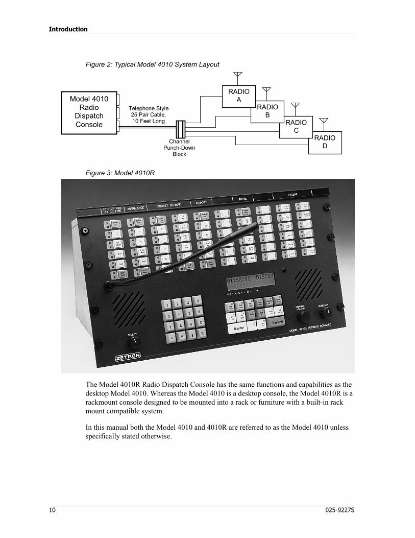
The diagram in Figure 2 illustrates a Model 4010 Radio Dispatch Console configured with four radio channels. A console can be configured with up to 12 radio channels.
Introduction
10 025-9227S
Figure 2: Typical Model 4010 System Layout
Figure 3: Model 4010R
The Model 4010R Radio Dispatch Console has the same functions and capabilities as the desktop Model 4010. Whereas the Model 4010 is a desktop console, the Model 4010R is a rackmount console designed to be mounted into a rack or furniture with a built-in rack mount compatible system.
In this manual both the Model 4010 and 4010R are referred to as the Model 4010 unless specifically stated otherwise.
RADIOD
RADIOC
RADIOB
RADIOAModel 4010
RadioDispatchConsole
Telephone Style25 Pair Cable,10 Feet Long
ChannelPunch-Down
Block
11
Manuals
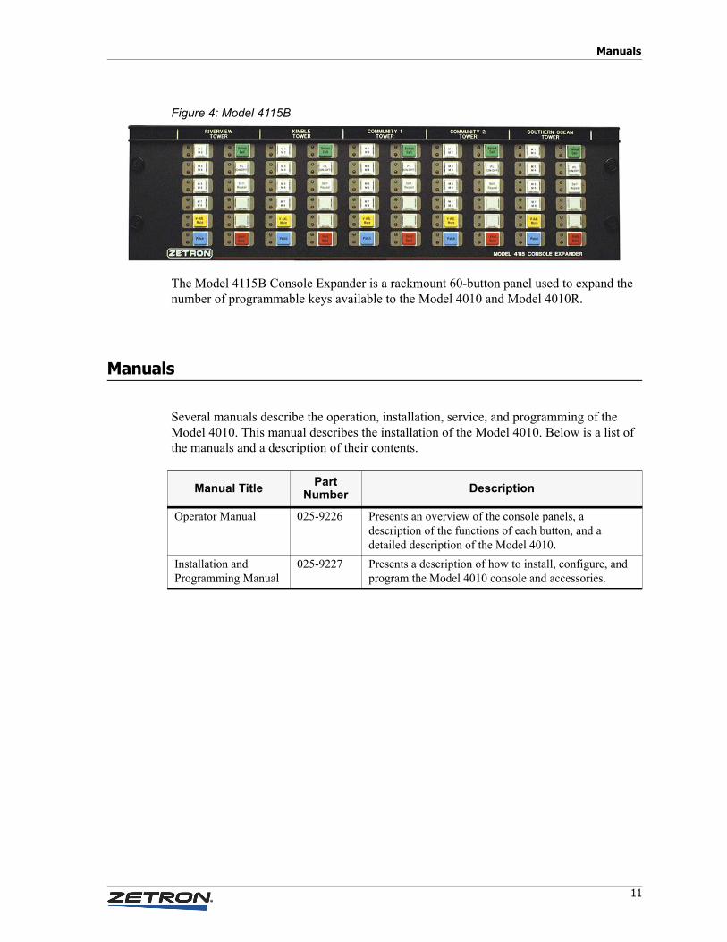
Figure 4: Model 4115B
The Model 4115B Console Expander is a rackmount 60-button panel used to expand the number of programmable keys available to the Model 4010 and Model 4010R.
Manuals
Several manuals describe the operation, installation, service, and programming of the Model 4010. This manual describes the installation of the Model 4010. Below is a list of the manuals and a description of their contents.
Manual Title Part Number Description
Operator Manual 025-9226 Presents an overview of the console panels, a description of the functions of each button, and a detailed description of the Model 4010.
Installation and Programming Manual
025-9227 Presents a description of how to install, configure, and program the Model 4010 console and accessories.
Introduction
12 025-9227S
Specifications
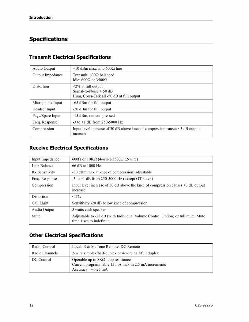
Transmit Electrical Specifications
Receive Electrical Specifications
Other Electrical Specifications
Audio Output +10 dBm max. into 600Ω lineOutput Impedance Transmit: 600Ω balanced
Idle: 600Ω or 3500ΩDistortion <2% at full output
Signal-to-Noise > 50 dB Hum, Cross-Talk all -50 dB at full output
Microphone Input -65 dBm for full outputHeadset Input -20 dBm for full outputPage/Spare Input -15 dBm, not compressedFreq. Response -3 to +1 dB from 250-5000 HzCompression Input level increase of 30 dB above knee of compression causes <3 dB output
increase
Input Impedance 600Ω or 10KΩ (4-wire)/3500Ω (2-wire)Line Balance 66 dB at 1000 HzRx Sensitivity -30 dBm max at knee of compression; adjustableFreq. Response -3 to +1 dB from 250-5000 Hz (except GT notch)Compression Input level increase of 30 dB above the knee of compression causes <3 dB output
increaseDistortion < 2%Call Light Sensitivity -20 dB below knee of compressionAudio Output 5 watts each speakerMute Adjustable to -28 dB (with Individual Volume Control Option) or full mute. Mute
time 1 sec to indefinite
Radio Control Local, E & M, Tone Remote, DC RemoteRadio Channels 2-wire simplex/half-duplex or 4-wire half/full duplexDC Control Operable up to 8KΩ loop resistance
Current programmable 15 mA max in 2.5 mA increments Accuracy +/-0.25 mA

13
Specifications
Console Power Requirements
Power Supply (802-0092) Specifications
Physical Specifications
Tone Control 15 standard tones supported programmable (no trimmer adjustment) 650 to 2050 Hz High Level Guard Tone duration 120/600 mSec Function Tone Duration 40 mSec Guard Tone Frequency 2175 Hz Tone frequency accuracy +/- 0.2%; timing accuracy +/-1.0%
Local Control PTT normally open relay contact rated 1.0 A at 24 VAC/DC
E & M Control TX control via PTT relay, external 48V requiredBusy Channel Detect Local Cross-Busy detection
Guard Tone or DC Control detection (LOTL) optionalRecorder Outputs 1 per channel (TX/RX audio summation), plus 1 output per console (various
combinations of select, unselect and microphone audio) 0 dBm level, 600Ω, single-ended outputs
Capacity 12 radio channels plus 1 or 2 phone lines with an optional phone patch cardOperating Temp. +5° to +50° Celsius
Voltage +13.5 VDC (+11.5 VDC minimum — +16.0 VDC maximum)Current 2.5 amperes maximum
Voltage +13.5 VDC ± 0.5 volts Current 7 amperesAC Input 95 to 250 VAC, 47 to 63 HzApproval CE
Model 4010
Size height = 9″ x width = 18″ x depth = 14″ inchesWeight 15 pounds
Model 4010R
Size height = 10.5″ x width = 19″ x depth = 10.5″ inchesWeight 15 pounds
Model 4115B
Size height = 5.25″ x width = 19″ x depth = 2.25″ inchesWeight 4 pounds

Introduction
14 025-9227S
Overview
System Description
The Model 4010 Radio Dispatch Console is a single position unit that has many built-in features. The Model 4010 is a desktop unit, and the Model 4010R is a rackmount unit. Both units have identical features and capabilities and are referred to as the Model 4010 in this manual unless specifically stated otherwise. Up to three positions may be paralleled for multioperator applications with fairly simple wiring. If more positions are necessary, contact Zetron Technical Support.
The console has individual channel volume, clock and volume meter, all-mute, simulselect, alerts, site intercom, instant transmit, and individual channel frequency/PL select. The unit can be configured between 2 and 12 channels in increments of two channels. The console is self-contained and interfaces directly to base station or repeater wire lines.
The Model 4010 has a built-in paging encoder which is capable of generating all popular signaling formats, including: Motorola/GE Two-Tone, and DTMF. Rotary Dial (1500 Hz or 2805 Hz), Plectron, Quick-Call 1 (2+2), and 5/6 Tone Sequential are available as an option with Extended Call Paging. With the Instant Call Paging option, these tones can be automatically routed to the proper channel. Without this option, the tones must be manually routed. This Instant Call Paging option also allows individual control buttons to be programmed to send one or an entire sequence of pages.
Each channel can be optioned to support a mix of control types: DC remote, tone remote, local control, and E&M control. The DC remote control requires one optional DC Control Daughter Board per DC channel. This DC Control Daughter Board also has a line-operated transmit light (LOTL) to show if a channel is in use via another source. The tone remote control requires one optional Tone Remote System Adapter Board per system. Each channel that requires tone control can now be configured with the channel option jumpers. If a channel requires LOTL indication, a Tone Remote LOTL Daughter Board is then added for that specific channel.
A Phone Patch Card is an option that allows the console operator to establish a patch between any radio channel and a telephone line. The card can have either one or two telephone interfaces. The console can also function as a hands-free, single-line or dual-line telephone, giving the operator the ability to receive and place telephone calls from the console. Only one card can be added per system. It does not require one of the dual channel slots.
The Expanded Auxiliary I/O Card adds input and output capabilities over the standard 8 inputs and 8 outputs available. This card does require one of the Dual Channel Card slots.
The Model 4115B is a rackmount panel, which allows the system to be configured with an additional 60 programmable switches. The system can accept a maximum of two expansion panels. The Console Programming System (CPSW) is used to define the function of the additional panel(s).

15
Overview
The console can be configured with a variety of communication options. The standard options are desk microphone, gooseneck microphone, or PTT handset with cradle, and/or headset. A PTT footswitch is also available to control transmissions.
Installation Sequence
Prior to installation, you are encouraged to review this manual as well as the Operator’s Manual. This will help your understanding of the system and will ease the installation. This manual is laid out section-by-section, in the sequence in which the system should be installed. If you should need help during installation, call Zetron.
Planning
Installation begins with planning the system layout. It is best to consider carefully the placement of the console and its options, the wiring to a punch-down block, and to the radios. The channel I/O connectors are laid out with four channels per the 50 pin Amphenol-type connector and one punch-down block is required per four channels.
Mapping
Card-slot mapping allocates a particular channel and console card slot to your base stations. It also creates a cross-reference between the channel and position names that you are familiar with. After the card-slots have been mapped, the channel and console should be configured using their various jumpers and switches.
Wiring
After the system has been configured, then wiring of the system may begin. The system will require wiring between the Console and any punch-down block, the radio base station, and between the consoles and their various accessory options (microphones, recorders, encoders, etc.).
Testing
When planning, mounting, configuring, and wiring have been completed, the system is ready for its first installed test. The components have been tested at the Zetron factory, but it is necessary for you to perform a preliminary system check in order to verify the proper configuring and wiring.
Level Setting
The last step is to adjust the audio levels in the system. Adjustments must be per-formed for the receive and transmit audio levels at every channel, and audio levels within the console.

Introduction
16 025-9227S
Operation
During its initial operation, the system will operate according to the programming done at the Zetron factory. If you wish to alter operation through programming, see Programming on page 79. Changes in the programming may be performed by you once the system is installed.
Overview
17
Console Installation
Overview
The Model 4010 Communication Console is a self-contained unit, which makes for an easy installation. Accessories may be added to the console including headset jack box, desk microphone, handset (desktop unit only), gooseneck microphone, footswitch, and telephone/radio headset interface. The handset and gooseneck microphone options are installed at the factory if ordered with the console. They are also an easily added option if ordered later. Instructions for installing options are included in the following chapter, Option Installation on page 47.
Major sections in this chapter:• Important Notes on page 18• Physical Installation on page 18• Power on page 19• System Grounding on page 20• Slot Mapping on page 21• Configuring Dispatch Consoles on page 24• Configuring Dual Channel Cards on page 26• Wiring to the Channels on page 31• Split 50 66m Type Punch-Down Block on page 35• Inputs and Outputs on page 37• Outputs on page 38• Auxiliary Audio on page 39• Labeling on page 39• Model 4115B Connections on page 40• Preliminary System Check on page 41• Level Adjustments on page 42

Console Installation
18 025-9227S
Important Notes
New Units
The Model 4010 Communication Console you have received is fully functional and calibrated to a factory standard of 0 dBm for both RX and TX levels. The line terminations are set at low impedance (600 Ω). You will need to reset RX and TX levels for the radio types and wiring configuration at each site.
It is important to set the impedance of the audio lines to high when connecting the channel card audio lines in parallel with another 4010 system or remote unit. One device remains at low impedance (600 ohm) and the remainder are set to high. See Configuring Dual Channel Cards on page 26 for setting the termination jumpers.
Program/Run Switch
The Model 4010 is programmed by sending a configuration file to it from a PC over a temporary serial connection. The configuration data is stored in write-protected memory, so writing must first be enabled by the program/run switch located on the bottom of the unit. Do not move this switch unless programming or checking the options in the 4010. On a desktop Model 4010, this switch is located on the bottom of the unit. The "normal" or "run" switch position is to the right (towards the Unselect speaker). Detailed programming instructions are provided in Programming on page 79.
Physical Installation
Console Location
When preparing to place the control panels, consider the amount of tabletop space required not only for the console, but also for a writing surface for the operator. Also, consider where accessory items such as microphones, foot switches, and headset jack-boxes may be placed. Another consideration is how close the placement will be to a power outlet. A solid earth ground must be provided.
Console Access
The channel connectors of the Model 4010 Console and option wiring are accessed from the rear of the unit. Routing of the channel wires to the common connector block must be considered. The rear of the unit also has the channel status lights, which need to be monitored during system verification and troubleshooting. To gain access to insert channel cards or to make channel or console adjustments, the top of the desktop console is opened in a clamshell fashion that requires about 17 inches of vertical space. A service loop on the

19
Power
wiring may be necessary for ease of access. The rack-mount console requires the removal of two screws that hold the top cover on. Access to the cards is then from the top of the unit and probably requires the unit to be removed from the rack or furniture enclosure.
Power
Primary Power
The Model 4010 requires an external 2.5 Ampere, 13.5 VDC regulated supply. The minimum input voltage of the console is 11.5 VDC and maximum of 15 VDC. Zetron P/N 802-0092 provides 7 Amps, 13.5 VDC ± 0.5 volts, with a DIN connector to mate with the input power connector J5. The module operates with an input of 95 to 250 VAC, 47 to 63 Hz, and is UL, CSA, VDE, and CE approved. The pin connections are as follows:
The console is equipped with an internal fuse. This is labeled F1 on the Control Board near the input power connect J5. The fuse is accessible by lifting the top cover of the unit. If replacement is required, replace only with 2.5-ampere, slow-blow AGC-type fuse.
Auxiliary Power
A connection for auxiliary power is also provided internal to the unit. Screw terminal connector J16 is used to connect +12 VDC and ground. The specifications for the auxiliary DC voltage is the same as the main supply, however the voltage level must not exceed the main supply by more than 2.5 VDC or drain on the auxiliary supply may occur. The auxiliary supply is automatically connected when the primary voltage drops more than 3.5 VDC below the voltage of the auxiliary supply.
Connection to the auxiliary is made through the wiring access hole in the back of the unit. The three-position screw terminal strip J16 is used for connection and AWG #18 stranded
J5 PIN SIGNAL
1 PWR-2 Open3 PWR+4 PWR-5 PWR+
Shell Chassis GND

Console Installation
20 025-9227S
wire is recommended. Strip the ends of the wire back 0.25 inches and insert into J16 and secure by screwing down the terminal. The pin connections are as follows:
System Grounding
Proper earth grounding is an important electrical consideration. The earth ground protects the system and personnel from lightning strikes, provides a path for any electrostatic discharge (ESD), and provides a solid reference for the system. Improper grounding of the system could cause susceptibility to ESD, induced noise from input power wiring, and reduced effectiveness of lightning protection devices. Induced noise could cause false signal indications or a variety of system errors.
A “star” grounding system (a single point ground to which satellite grounds are connected) is the best grounding system. The central star point must be firmly attached to a low-impedance earth ground point, such as a ground rod.
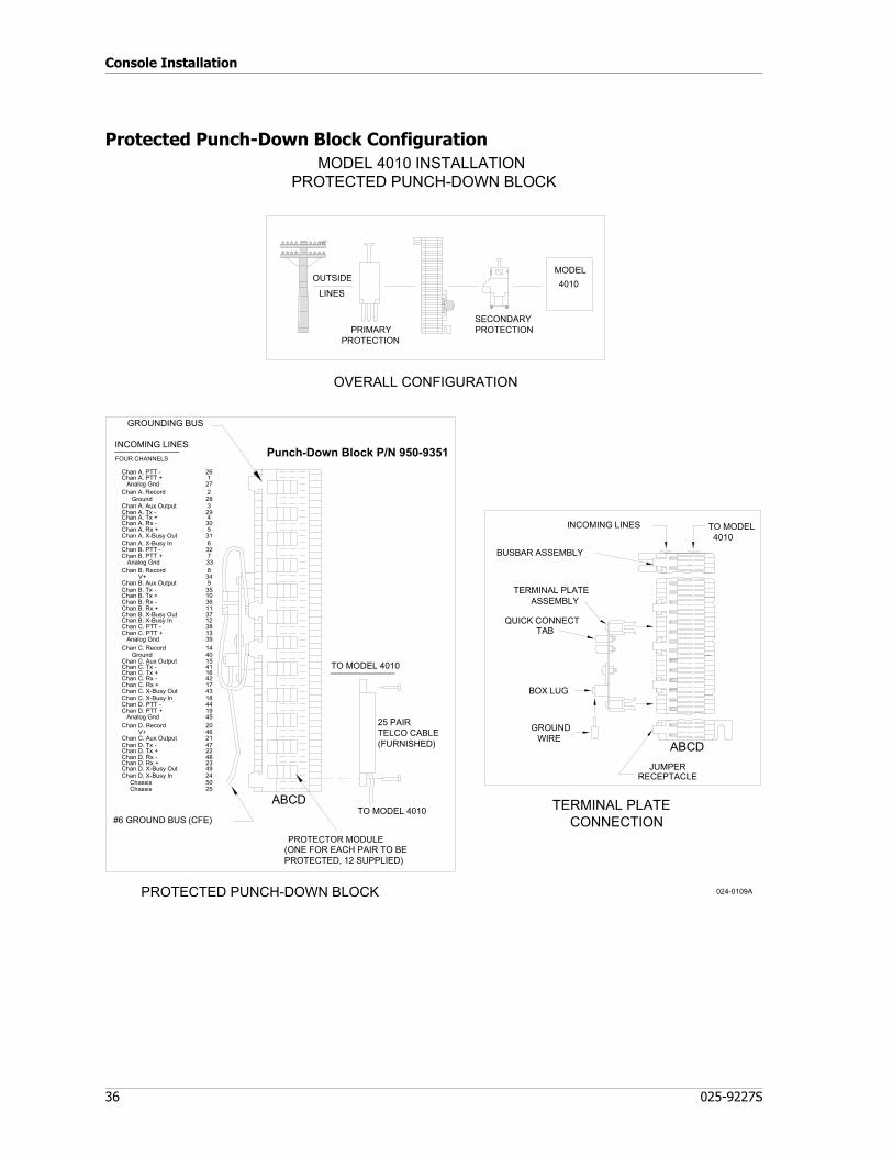
If protective punch-down blocks are used, a large diameter (6-gauge) copper conductor (or equivalent braided strap/ bus bar) must be connected between the ground lug of each block and the earth ground or central star grounding point. With the protected punch-down blocks, it is best to wire directly to the earth ground if possible. Each piece of equipment should have its chassis grounded to the central star point with a separate ground wire. The gauge of the wire depends on the length of the run, 12 gauge is adequate if the length is less than 15 feet. The length of the runs should be minimized. Securely connect a grounding wire to the case of each unit making sure that a metal-to-metal connection is made (no paint or oxidation layer). Most Zetron equipment provides a grounding stud. Figure 5 shows a central star grounding system.
All earth grounds in the system should be isolated from signal lines. It is easy to couple ESD or lightning noise spikes if these lines run parallel for any distance. The AC power
J16 PIN Location SIGNAL
1 Nearest to channel card slot PWR+2 Center terminal PWR-3 Nearest to side of case PWR-
Warning! Improper system grounding can cause electric shock to personnel, damage to equipment, and system malfunctions.
STOP

21
Slot Mapping
wires (and DC power to a lesser degree) should also be routed separately. AC lines can have large switching current noise spikes that could couple into signal lines.
Figure 5: Typical Star Grounding System
Slot Mapping
Slot mapping gives a reference of the channel number, type of channel, channel nomenclature, and plug designator used throughout this and other manuals. The slot map is necessary in order to complete the configuration and wiring of the system, and necessary to maintain the system. Usually the Zetron factory will prepare a slot map to your specifications, especially if you requested factory programming, since the map is required before the system can be programmed. If prepared at the factory, you will find a copy of your slot map with this manual. Even if the slot map has been provided, you are encouraged to continue to read this section.
The first step in preparing your slot map is to become familiar with the channel cards and option boards contained in the console. Open the desktop console by unscrewing the two
Caution! Do not connect signal ground to the central star ground. The conditioning and reference of the signal grounds is controlled inside the Zetron equipment. The system will be more susceptible to noise interference.
!
PowerSupply
Jack Box
Console
ProtectedPunch-Down
Block 3
ProtectedPunch-Down
Block 2
ProtectedPunch-Down
Block 1
Grounding stud onConsole Back

Console Installation
22 025-9227S
latches on the back of the console and lifting the top open. The rack-mount console has two screws that hold the top cover on located on the back of the unit.
Figure 6 shows the view of the desktop console with the top opened. You will notice several card slots designated J6-J12. Since the system is tested at the Zetron factory, you will find the channel cards already plugged into the assigned slots. Slots J12-J7 are for channel cards or Auxiliary I/O boards. J6 is for the Phone Patch card. On the back of the unit are three 50-conductor male Amphenol-type plugs used to connect the Console to the punch-down blocks and radios. These are designated J4 (channels 1-4), J3 (channels 5-8), and J2 (channels 9-12).
Figure 6: A Model 4010 with its case open
Caution! Keep the front of the desktop unit on the tabletop, do not let the front hang over a table edge. The console can be knocked off balance onto the floor in this position.
!

23
Slot Mapping
Table 1: Slot/Card Compatibility Matrix
Slot Card Compatibility
J12 Dual Channel Card, channels 1-2 Aux I/O CardJ11 Dual Channel Card, channels 3-4 Aux I/O CardJ10 Dual Channel Card, channels 5-6 Aux I/O CardJ9 Dual Channel Card, channels 7-8 Aux I/O CardJ8 Dual Channel Card, channels 9-10 Aux I/O CardJ7 Dual Channel Card, channels 11-12 Aux I/O CardJ6 Phone Patch Card, line 1-2

Console Installation
24 025-9227S
Configuring Dispatch Consoles
The console has several jumper selectable configuration options. Table 2 shows the various options and the normal factory setting. See Model 4010 Dual Channel Card Layout on page 103 for the location of these jumpers.
Table 2: Model 4010 Control Board Jumpers and Switches
Jumper Options Notes
JP1 Recorder Output & VU meter The audio recorder output and the VU meter include the console microphone transmit audio and its Select receive audio. Place the jumper in position B to add Unselect receive audio as well.
A* Unselect audio not sent to Recorder/VU
B Unselect audio mixed with Select audio to Recorder Output and VU
JP2 Auxiliary Audio to Select Audio The transmitted audio from the auxiliary audio input may be monitored with the Select speaker. For example, when an external encoder is used, the operator can hear the encoder tones as they are being transmitted.
A* Auxiliary audio mixed with Select audio on Select speaker
B Auxiliary audio disabled
JP3 Unselect Speaker / Headset & Handset Audio Determines where Unselect audio is heard. You might want to change this if, for example, you want the Unselect speaker to turn off when the software detects a handset lifted from a cradle or a headset plugged into a jack.
A* Unselect audio always on unselect speaker
B Unselect audio switch under software control
C Unselect audio always on headset/handset
JP4 Headset/Handset Unselect Monitor Occasionally, it is desirable to monitor both Select and Unselect audio on the earpiece of the headset or handset. Jumper JP4 may be used to enable the Unselect audio monitoring.
A* Unselect audio not heard at headset/handset
B Unselect audio heard at headset/handset
JP5 Auxiliary Audio input impedance If an external encoder is used, use JP5 to set the input impedance of the Model 4010 to match the output impedance of the encoder.
A* Auxiliary Audio 600 Ω impedance
B Auxiliary Audio 10 kΩ impedance
JP6 Select Speaker / Headset & Handset audio Determines where Select audio is heard. You might want to change this. For example if you want the Select speaker to turn off when the software detects a handset lifted from a cradle or a headset plugged into a jack.
A Select audio always on select speaker
B* Select audio switch under software control
C Select audio always on headset/handset
JP7 Tone generator input filter The output of the tone generator has an additional high frequency filter that can be inserted. This filter is not required, in which case the jumper should be left in position A.
A* No tone filter
B Tone filter connected
JP8 Reserved for use with the TRHI. See Telephone/Radio Headset Interface on page 53.
JP9 Not used.
JP10 Operator Paging/Alert/Warning Audio Operator audio refers to the paging and alert/warning tones generated by the M4010. These tones can be irritating when monitored by the dispatcher, depending on where it is heard and how loud it is. The level is adjusted by R104.
A* Operator Audio to Select Speaker
B Operator Audio to Unselect Speaker

25
Configuring Dispatch Consoles
Model 4010 Options
The Model 4010 console may be shipped with optional features that deviate from standard operation. There is a method to determine what options are enabled in a particular console. The Model 4010 has a programming switch located on the bottom of the console. Put the programming switch in the program position* for approximately one second and then return it to the normal run position while pressing the # key on the keypad. As long as the # key is held down the option code may be read from the LCD display.
If no options are installed in the unit then the display will show “Opt:-”. If there are options enabled in the unit then “Opt:” will be followed by one or more letters indicating the options enabled. Use Table 3 to interpret the letters appearing after the prompt.
Table 3: Model 4010 Console Option Code Definition
Note In Table 2, the asterisk (*) is used to show the typical position of a jumper. However, the M4010 is configured and programmed at the factory according to various customer preferences, so your default positions from the factory may be different than the typical positions listed here.
Note * On the Model 4010, the “program” position is toward the Select speaker.
Option Code Description Default
B DC I Boost enabled. For DC channels only, this provides an initially boosted current to overcome greater capacitance found in longer wire runs. After the initial boost, current returns to normal levels.
DC I Boost disabled. Normal current levels are used.
D D-PTT always selects the desk mic. This option is required when using both a desk mic and a gooseneck mic at the same time.
A contact closure on D-PTT selects the dynamic input programmed by CPSW.
C Coded/Clear TX feature enabled. For tone control only, this allows encrypted control of the base station.
Coded/Clear TX feature disabled.
X Extended Paging enabled. This adds several paging formats: Rotary Dial/1500 Hz or 2805 Hz, Plectron, Quick-Call I (2+2), and 5/6 Tone Sequential.
Paging formats are limited to Motorola Two-Tone, GE Two-Tone, DTMF, and alert tones.
I Instant Call Paging enabled. This allows frequently used pages or sequences of pages to be initiated and automatically steered to the correct channel with a single key press.
Instant Call Paging disabled. All pages are entered manually.
If an option code is not displayed, that option is set to the default condition.

Console Installation
26 025-9227S
Some options require purchasing. To inquire about changing options to a Model 4010 console already in service, please contact Zetron’s Technical Support.
Configuring Dual Channel Cards
Now that the system slot map has been developed, you know the allocation of channels and you can configure each Dual Channel Card (DCC) to meet the requirements of the channel pairs. Card configuration is usually performed at the Zetron factory to comply with the customer’s system configuration request, but it must be checked when installed at the end user's site. The following will be useful for understanding the options available and for system modifications or additions.
The first step is to label each card with your names for channel A and B. This is helpful so that once configuration and adjustments have been made, the card will not be placed in a wrong slot, which probably has different configuration and adjustment requirements.
Channel Type
Each channel in the Model 4010 can be programmed to be one of three control types: Local, Tone, or DC. This programming is performed using CPSW software. Refer to Channel Configuration on page 85 for details.
In addition to programming, there are some jumper and switch settings that must be reviewed.
Local Control
This is the default for all channels and no additional hardware is required. If a Tone Remote Adapter is installed, then the DCC’s Guard Tone Enable jumpers (JP4 and JP6) must be set to position A to disable the low-level guard tone.
Tone Control
To have any tone control channels, a Tone Remote Adapter must be installed (only one is required for all channels). In addition to programming, the DCC’s Guard Tone Enable jumpers (JP4 and JP6) must be set to position B.
DC Control
For a channel to be DC controlled, the DC remote adapter board must be installed. One adapter is required for each channel that is to be set to DC. Jumpers (JP4 and/or JP6) must be in the A or Local position; however, if a DC module is installed on a channel defined in CPSW as local, a card error will be displayed on the console. Programming allows the DC type to be set as momentary or constant.

27
Configuring Dual Channel Cards
The Dual Channel Card has several jumper and switch selectable options. The configuration switches of the Dual Channel Cards are located at the bottom rear edge of the dual channel card and labelled on the back panel. There are eight switches in two halves. The top four are labeled for an odd channel (or channel A on the card) and the bottom four are labeled for an even channel (or channel B on the card). See Table 4.
To make jumper verification easier, the console may be powered down and the Dual Channel Card taken from its card slot by removing the one mounting screw from the back panel and pulling the card up and towards the front of the unit. This will allow the LEDs to clear their rear panel openings. To install the card, insert the front edge of the connector first and push down and towards the rear panel. Verify that the LEDs line up properly while positioning. Reinstall the screw through the back panel to the bracket on the card.
The subsections following Table 4 describe the jumper/switch option settings.
Table 4: Dual Channel Card Jumpers and Switches
Caution! The cards in a Model 4010 are not hot swappable in the unit. You must power the unit off before any cards can be safely removed or added to the system.
Caution! When comparing the DIP switch’s ON/OFF labelling with the Model 4010’s ON/OFF labelling, the installer might notice that the direction of ON and OFF disagree.
The ON and OFF directions provided in Table 4 are intended to be used with the Model 4010 silkscreen labelling.
!
!
Option Name Channel A Channel B Notes
2W Line Termination
See Line Termination on page 28.
Low Impedance (600Ω) JP1-A JP7-AHigh Impedance (3.5 KΩ) JP1-B JP7-B
4W Line TerminationLow Impedance (600Ω) JP2-A JP3-AHigh Impedance (10 KΩ) JP2-B JP3-B
Guard Tone Enable Disable for local control or DC channels. Enable for tone control channels.
Guard Tone disabled JP4-A JP6-AGuard Tone enabled JP4-B JP6-B
Busy Transmit Inhibit (BTI)See Busy Transmit Inhibit on page 28.BTI enabled SW1-1-ON SW1-5-ON
BTI disabled SW1-1-OFF SW1-5-OFFChannel Cross Muting (CCM)
See Channel Cross-Mute on page 29.CCM disabled SW1-2-OFF SW1-6-OFF
CCM enabled SW1-2-ON SW1-6-ON

Console Installation
28 025-9227S
Line Termination
The transmit audio output and receive audio input may be configured for low-impedance or high-impedance. For systems with only one control point on a channel, the channel should be configured for low-impedance (600 Ω). For systems with multiple control points on a channel, all but one parallel-connected channel should be configured for high-impedance. One control point in a multiple control point system should be configured for low-impedance termination, and this should be the channel card at the far end of the transmission line from the base station.
Low-impedance configurations present a 600Ω impedance on the transmit and receive lines at all times. High-impedance configurations present a 3500Ω (or greater) impedance on the transmit/2-wire receive line while idle, and 600Ω while transmitting. On the 4-wire receive line, high-impedance is 10,000Ω at all times.
Busy Transmit Inhibit
Each channel may be configured to either allow or inhibit transmission on a Busy channel. A channel is Busy whenever its cross-busy input (Busy In) is activated by a locally paralleled control point, or when its line-operated transmit light (LOTL) is activated by a remotely paralleled control point. Usually inhibiting while busy is desired to prevent confused communications and to keep proper line terminations and levels. However, when line conditions cause falsing of the LOTL, it is desirable to be able to transmit even while busy.
Option Switch (OPT) - function depends on type of channelTone Control
See Tone Control, HLGT Duration on page 29.Standard HLGT Duration SW1-3-OFF SW1-7-OFF
Custom HLGT Duration SW1-3-ON SW1-7-ONDC Current Control See DC Current Control —
Current Selection on page 29.
Zetron standard levels SW1-3-OFF SW1-7-OFFMotorola/GE currents SW1-3-ON SW1-7-ON
Full Duplex (FD)See Full Duplex on page 29.FD disabled SW1-4-OFF SW1-8-OFF
FD enabled SW1-4-ON SW1-8-ONLOTL
See LOTL Disable on page 29.LOTL enabled JP1-A * N/A
LOTL disabled JP1-B * N/A* JP1 in this instance refers to jumper JP1 on the daughter board, not the Dual Channel Card.Jumpers JP5 and JP8 are fixed in place and should not be changed.
Option Name Channel A Channel B Notes

29
Configuring Dual Channel Cards
Channel Cross-Mute
Each channel may be configured so that the external cross-busy input (Busy In) will also mute the receive audio of the channel to all console positions. This is useful to prevent audio feedback between consoles present in the same room.
If you need to cross mute more than three consoles, call ZETRON Technical Support for guidance.
Tone Control, HLGT Duration
When a channel is programmed for tone remote control, the OPT switch allows selection between the standard HLGT (high-level guard tone) duration (120 milliseconds) or the custom HLGT duration (defined via CPSW). Placing the switch in the OFF position selects the standard duration. Placing the switch in the ON position selects the custom duration.
DC Current Control — Current Selection
To control transmission using DC current, the optional DC Remote Daughter Board must be installed on the Dual Channel card for that specific channel. When the daughter board is installed, the OPT switch controls the current setting level for transmission. In the OFF position, the standard Zetron level, which is appropriate for most applications, is used. In the ON position, the standard Motorola/GE settings are used.
Full Duplex
Each channel may be configured for full duplex or simplex operation. Full duplex operation requires a 4-wire system and allows the dispatcher to transmit and receive simultaneously (like a telephone). Simplex (or half-duplex) operation may either be a 2-wire or 4-wire system, and allows the dispatcher to transmit or receive but not both simultaneously. This switch selectable option prevents dispatchers in full duplex operation from hearing themselves, and thus prevents feedback.
LOTL Disable
The option boards, DC Remote Daughter Board and Tone Remote LOTL Daughter Board, may be configured to ignore LOTL parallel remote transmit signals. Note that when parallel control points are used, the FCC requires that the LOTL function be enabled. If no parallel control points are installed, it may be desirable to disable the LOTL function, because when enabled, the LOTL function operates even when this console is transmitting.

Console Installation
30 025-9227S
Channel VOX Hang Time
The VOX signal is used to activate the unit CALL LED and to control patch transmission. The hang time of the CALL LED is programmable via CPSW, allowing the CALL indicator to remain on for a number of seconds after the actual voice activity ends. The hang time for patching is controlled by the channel or telephone card VOX circuit. Experience has shown that an optimal patch hang time is about one second, which is the factory default. Contact Technical Support if you need to change this timing.
31
Wiring to the Channels
Wiring to the Channels
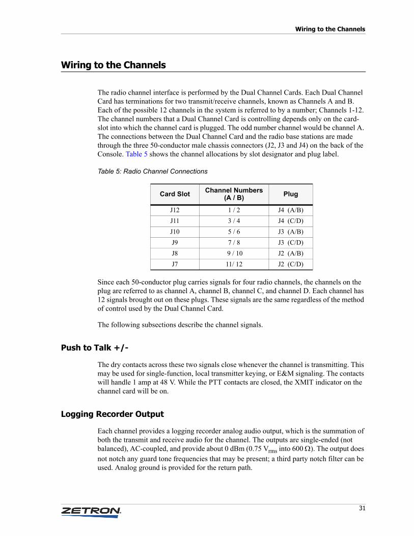
The radio channel interface is performed by the Dual Channel Cards. Each Dual Channel Card has terminations for two transmit/receive channels, known as Channels A and B. Each of the possible 12 channels in the system is referred to by a number; Channels 1-12. The channel numbers that a Dual Channel Card is controlling depends only on the card-slot into which the channel card is plugged. The odd number channel would be channel A. The connections between the Dual Channel Card and the radio base stations are made through the three 50-conductor male chassis connectors (J2, J3 and J4) on the back of the Console. Table 5 shows the channel allocations by slot designator and plug label.
Table 5: Radio Channel Connections
Since each 50-conductor plug carries signals for four radio channels, the channels on the plug are referred to as channel A, channel B, channel C, and channel D. Each channel has 12 signals brought out on these plugs. These signals are the same regardless of the method of control used by the Dual Channel Card.
The following subsections describe the channel signals.
Push to Talk +/-
The dry contacts across these two signals close whenever the channel is transmitting. This may be used for single-function, local transmitter keying, or E&M signaling. The contacts will handle 1 amp at 48 V. While the PTT contacts are closed, the XMIT indicator on the channel card will be on.
Logging Recorder Output
Each channel provides a logging recorder analog audio output, which is the summation of both the transmit and receive audio for the channel. The outputs are single-ended (not balanced), AC-coupled, and provide about 0 dBm (0.75 Vrms into 600 Ω). The output does not notch any guard tone frequencies that may be present; a third party notch filter can be used. Analog ground is provided for the return path.
Card Slot Channel Numbers(A / B) Plug
J12 1 / 2 J4 (A/B)J11 3 / 4 J4 (C/D)J10 5 / 6 J3 (A/B)J9 7 / 8 J3 (C/D)J8 9 / 10 J2 (A/B)J7 11/ 12 J2 (C/D)

Console Installation
32 025-9227S
Auxiliary Output
This open-collector output pulls to ground when the standby-base feature for the channel is activated. This output will sink 500 mA to 0.8 V when active, and will withstand no more than 12 V when inactive. Ground is provided for the return path.
Transmit Audio +/-
This is the balanced source for transmit audio. Normally, the impedance of this output is 600Ω, however, with the replacement of a jumper, this output can be made to go to 3500Ω when not actually sourcing audio. This can be useful for paralleling control stations on the same set of wires. The output is isolated for voltages up to 1500 VAC.
The TX Audio signal wires are also used for receiving audio in a 2-wire system. The 2-wire receive sensitivity may be adjusted to -30 dBm using the 2W RX adjustment on the channel card.
Receive Audio +/-
This is the balanced input for receive audio in a 4-wire system. Normally, the impedance of this input is 600Ω, however, with the replacement of a jumper, this input can be made to go to 10,000Ω useful for paralleling multiple control points. The output is isolated for voltages up to 1500 VAC. The 4-wire receive sensitivity may be adjusted to -30 dBm using the 4W RX adjustment on the channel card edge.
Cross-Busy Input/Output
This input/output pair is used for cross-busy handshaking for multiple parallel control point arbitration. The X-Busy Output sinks current to ground when the channel is being transmitted upon. The X-Busy Input inhibits transmission on the channel while the input is grounded (or within 1 volt). The output will sink up to 0.5 amperes at 0.8 V when active, and will tolerate no more than 12 V when inactive. The input represents a 3300Ω load to +12 VDC but will withstand up to 25 V across its signal. While the X-Busy Input is active, the BSY-I indicator on the channel card will be on. If enabled via the BTI and CCM DCC DIP switch segments (and the Bsy-Out connector block terminals are wired to the appropriate Bsy-In terminals), the X-Busy Input will mute the audio of the channel when the input is active.
Note The transmit audio level may be adjusted close to +10 dBm using the TX adjustment on the channel card.
Tip The transmitting console will not busy itself out, even with its Busy Output connected to its Busy Input. This reduces the complexity of the wiring by allowing the installer to MUX those outputs and inputs together, not having to keep them separate.

33
Wiring to the Channels
Equivalent Circuits
The figures accompanying Table 6 illustrate the interface signals’ equivalent circuits and the plug connections on which they may be found. All pin numbers listed in the following table refer to the 50-pin connectors on the rear of the unit and correspond to the terminal numbering on the punch-down blocks.
Table 6: Equivalent Circuits for Console I/O
Table 7 summarizes the signals found on each channel plug. The table also contains the wire colors for the 25-pair cables often used to connect to the plugs.
2.2uF600 Ohm
600 Ohm
10K Ohm
2.2 uF 10K Ohm
3.3K Ohm
10K Ohm
+12V
+12V
600 Ohm10 uF
50-Pin Connector Pin NumbersJ2, J3, and J4
Ch-A Ch-B Ch-C Ch-D Signal
1 7 13 19 PTT +
26 32 38 44 PTT –
2 8 14 20 Record
27 33 39 45 Analog Ground
3 9 15 21 Aux Output
28 gnd 34 v+ 40 gnd 46 v+ Ground or V+
4 10 16 22 Tx Audio +
29 35 41 47 Tx Audio –
5 11 17 23 Rx Audio +
30 36 42 48 Rx Audio –
6 12 18 24 Busy Input
31 37 43 49 Busy Output

Console Installation
34 025-9227S
Table 7: Channel Plug Signals (J2, J3, J4) and 25-Pair Cable Colors
Signal Wire Color Connector Wire Color Signal
Chan A. PTT- White/Blue 26 -----------1 Blue/White Chan A. PTT+Analog Ground White/Orange 27 -----------2 Orange/White Chan A. Recorder OutDigital Ground White/Green 28 -----------3 Green/White Chan A. Aux OutputChan A. TX - White/Brown 29 -----------4 Brown/White Chan A. TX +Chan A. Rx - White/Slate 30 -----------5 Slate/White Chan A. Rx +Chan A. X-Busy Out Red/Blue 31 -----------6 Blue/Red Chan A. X-Busy In
Chan B. PTT- Red/Org 32 -----------7 Org/Red Chan B. PTT+Analog Ground Red/Green 33 -----------8 Green/Red Chan B. Recorder OutV+ Red/Brown 34 -----------9 Brown/Red Chan B. Aux OutputChan B. TX - Red/Slate 35 --------- 10 Slate/Red Chan B. TX +Chan B. Rx - Black/Blue 36 --------- 11 Blue/Black Chan B. Rx +Chan B. X-Busy Out Black/Org 37 --------- 12 Org/Black Chan B. X-Busy In
Chan C. PTT- Black/Green 38 --------- 13 Green/Black Chan C. PTT+Analog Ground Black/Brown 39 --------- 14 Brown/Black Chan C. Recorder OutDigital Ground Black/Slate 40 --------- 15 Slate/Black Chan C. Aux OutputChan C. TX - Yellow/Blue 41 --------- 16 Blue/Yellow Chan C. TX +Chan C. Rx - Yellow/Orange 42 --------- 17 Orange/Yellow Chan C. Rx + Chan C. X-Busy Out Yellow/Green 43 --------- 18 Green/Yellow Chan C. X-Busy In
Chan D. PTT- Yellow/Brown 44 --------- 19 Brown/Yellow Chan D. PTT+Analog Ground Yellow/Slate 45 --------- 20 Slate/Yellow Chan D. Recorder OutV+ Violet/Blue 46 --------- 21 Blue/Violet Chan D. Aux OutputChan D. TX - Violet/Orange 47 --------- 22 Orange/Violet Chan D. TX +Chan D. Rx - Violet/Green 48 --------- 23 Green/Violet Chan D. Rx +Chan D. X-Busy Out Violet/Brown 49 --------- 24 Brown/Violet Chan D. X-Busy In
Chassis Ground Violet/Slate 50 --------- 25 Slate/Violet Chassis Ground
Note First color is main color, second color is stripe.

35
Split 50 66m Type Punch-Down Block
Split 50 66m Type Punch-Down Block
P/N 950-9351Four Channels UPChan A. PTT - 26 — — — — 26Chan A. PTT + 1 — — — — 1
Analog GND 27 — — — — 27Chan A. Record 2 — — — — 2
Ground 28 — — — — 28Chan A. Aux Output 3 — — — — 3Chan A. TX - 29 — — — — 29Chan A. TX + 4 — — — — 4Chan A. RX - 30 — — — — 30Chan A. RX + 5 — — — — 5Chan A. X-Busy Out 31 — — — — 31 Signals shownChan A. X-Busy In 6 — — — — 6 for four channelsChan B. PTT - 32 — — — — 32Chan B. PTT + 7 — — — — 7
Analog GND 33 — — — — 33Chan B. Record 8 — — — — 8
V+ 34 — — — — 34Chan B. Aux Output 9 — — — — 9Chan B. TX - 35 — — — — 35Chan B. TX + 10 — — — — 10Chan B. RX - 36 — — — — 36Chan B. RX + 11 — — — — 11Chan B. X-Busy Out 37 — — — — 37Chan B. X-Busy In 12 — — — — 12Chan C. PTT - 38 — — — — 38Chan C. PTT + 13 — — — — 13
Analog GND 39 — — — — 39Chan C. Record 14 — — — — 14
Ground 40 — — — — 40Chan C. Aux Output 15 — — — — 15Chan C. TX - 41 — — — — 41Chan C. TX + 16 — — — — 16Chan C. RX - 42 — — — — 42Chan C. RX + 17 — — — — 17Chan C. X-Busy Out 43 — — — — 43Chan C. X-Busy In 18 — — — — 18Chan D. PTT - 44 — — — — 44Chan D. PTT + 19 — — — — 19
Analog GND 45 — — — — 45Chan D. Record 20 — — — — 20
V+ 46 — — — — 46Chan D. Aux Output 21 — — — — 21Chan D. TX - 47 — — — — 47Chan D. TX + 22 — — — — 22Chan D. RX - 48 — — — — 48Chan D. RX + 23 — — — — 23Chan D. X-Busy Out 49 — — — — 49Chan D. X-Busy In 24 — — — — 24
Chassis 50 — — — — 50Chassis 25 — — — — 25
Warning! Do not place a bridge clip across the V+ contacts (34-34 and 46-46).
STOP
Console Installation
36 025-9227S
Protected Punch-Down Block Configuration
PROTECTOR MODULE
BUSBAR ASSEMBLY
TERMINAL PLATEASSEMBLY
QUICK CONNECTTAB
BOX LUG
GROUNDWIRE
JUMPERRECEPTACLE
INCOMING LINES
MODEL4010
SECONDARYPROTECTIONPRIMARY
PROTECTION
OUTSIDE
LINES
TERMINAL PLATECONNECTION
OVERALL CONFIGURATION
PROTECTED PUNCH-DOWN BLOCK
MODEL 4010 INSTALLATIONPROTECTED PUNCH-DOWN BLOCK
024-0109A
(ONE FOR EACH PAIR TO BEPROTECTED, 12 SUPPLIED)
#6 GROUND BUS (CFE)
25 PAIRTELCO CABLE(FURNISHED)
GROUNDING BUS
INCOMING LINES_____________
TO MODEL 4010
TO MODEL 4010ABCD
ABCD
Chan A. PTT -Chan A. PTT + Analog Gnd Chan A. Record Ground Chan A. Aux Output Chan A. Tx -Chan A. Tx + Chan A. Rx -Chan A. Rx + Chan A. X-Busy Out Chan A. X-Busy In Chan B. PTT -Chan B. PTT + Analog Gnd Chan B. Record V+ Chan B. Aux Output Chan B. Tx -Chan B. Tx + Chan B. Rx -Chan B. Rx + Chan B. X-Busy Out Chan B. X-Busy In Chan C. PTT -Chan C. PTT + Analog Gnd Chan C. Record Ground Chan C. Aux Output Chan C. Tx -Chan C. Tx + Chan C. Rx -Chan C. Rx + Chan C. X-Busy Out Chan C. X-Busy In Chan D. PTT -Chan D. PTT + Analog GndChan D. Record V+Chan C. Aux OutputChan D. Tx -Chan D. Tx +Chan D. Rx -Chan D. Rx +Chan D. X-Busy OutChan D. X-Busy In Chassis Chassis
26 127 228 329 430 531 632 733 834 93510361137123813391440154116421743184419452046214722482349245025
FOUR CHANNELS
_____________
TO MODEL 4010
Punch-Down Block P/N 950-9351

37
Inputs and Outputs
Inputs and Outputs
The main board of the Model 4010 is equipped with eight inputs and outputs. These inputs and outputs can be used as auxiliary I/O, or as spare I/O. All inputs on the board must be one or the other (auxiliary or spare). All outputs must be one or the other (auxiliary or spare). By default, the I/O is set to spare inputs and outputs. See Input/Output Configuration on page 90 for an explanation of the differences between auxiliary and spare I/O.
Auxiliary I/O can be added by installing Auxiliary I/O Cards (see Model 4010 Auxiliary I/O Card on page 56). Each Auxiliary I/O Card adds six auxiliary inputs and six auxiliary outputs. There is no method for adding spare inputs or spare outputs.
Inputs
The Console has eight inputs, which are a standard feature and located on the Control Board (as are the outputs below). Inputs are programmed through CPSW (see Input/Output Configuration on page 90). Inputs are TTL compatible (0 to 5 VDC only) and accessible through the wiring access hole in the rear of the unit and wired to P8. The mating connector is provided with the unit. The pinout is shown in Table 8.
Table 8: P8 Inputs
Signal P8 Pin #
INPUT 1 1INPUT 2 2INPUT 3 3INPUT 4 4INPUT 5 5INPUT 6 6INPUT 7 7INPUT 8 8
(open) 9GROUND 10

Console Installation
38 025-9227S
Outputs
The Console has eight outputs, which can be programmed through CPSW. Outputs 1-4 are open collector drivers that can drive 0 to 25 VDC, 200 mA. Although the open collector outputs can each source 200 mA, only one collector output can be active at a time. If more than one is to be activated, the load should be no more than 100 mA.
Outputs 5-8 are relay outputs which have the common (C) and normally open (NO) contacts brought out to connector P7. These contacts are capable of 1 Amp and 50 V non-inductive load. Wiring access is through the rear of the unit. The mating connector is provided with the unit. The connector pinout is listed in Table 9.
Table 9: P7 Outputs
Output 1 has a special function that can be used to generate an off-hook signal for the TRHI (see Telephone/Radio Headset Interface on page 53).
Signal P7 Pin # Signal P7 Pin #
OUTPUT 1 1 OUTPUT 6 - NO 8OUTPUT 2 2 OUTPUT 7 - C 9OUTPUT 3 3 OUTPUT 7 - NO 10OUTPUT 4 4 OUTPUT 8 - C 11OUTPUT 5 - C 5 OUTPUT 8 - NO 12OUTPUT 5 - NO 6 GROUND 13OUTPUT 6 - C 7 GROUND 14

39
Auxiliary Audio
Auxiliary Audio
The console has additional audio signals available on connector P1 at the rear of the unit. Most of these signals are used when installing optional equipment. The mating screw terminal connector is supplied with the console. The connector pinout is listed in Table 10.
Table 10: Auxiliary Audio
Labeling
The push button switches of the control panels usually come from the factory with customer specified labeling installed. If for any reason, the labeling needs to be changed, the labels may be replaced in the field. Spare clear key tops are provided with the unit for future modification. The key tops are accessible by removing the push-button key top from its plastic plunger. Grasp the key top with thumb and forefinger placed on horizontal edges of the key. Gently pull the key top off. Pliers may be used, but care must be taken so not to slip and scratch the cover. Only the outer portion of the key should be grasped when removing to allow the lower locking rib to release. Use a rocking motion to release one side at a time.
Labels may be made of white or colored typing paper, upon which the desired words have been typed or photocopied. Guidelines for cutting the label to the proper size may be made
Signal P1 Pin #
BUSY OUT 1
SELECT AUDIO OUT 2
AUX AUDIO IN 3
AUX AUDIO COMMON 4
AUX PTT IN 5
PTT COMMON 6
D. MIC AUD IN+ 7
D. MIC AUD IN– 8
D. MIC PTT IN 9
PTT COMMON 10
MONITOR SW IN 11
MON COMMON 12
FOOTSWITCH 13
FS COMMON 14
COMB AUDIO OUT* 15
* Set JP1 to position B to enable unselect audio at pin 15. See Table 2 on page 24.

Console Installation
40 025-9227S
by lightly drawing a rectangle, .39" x .43" in dimension centered over the label words. Insert the label into the clear key top with the bottom of the label orientated toward the tabs of the key top. The key top is placed on the switch with the tabs down.
Model 4115B Connections
The expansion panel communicates with the dispatch console via a serial data loop. There may be a maximum of three panels per position: one dispatch console, and optionally two expansion panels. Each panel has a Loop In and a Loop Out connector. Every Loop Out must be connected to the Loop In of the next panel with the supplied four-conductor modular telephone-type cable. In this way, the data loops around from panel to panel in a daisy chain.
Power is supplied to the expansion panel via the loop cable from the Model 4010. Each panel is also protected by a fuse labeled F2, which is accessible via the cutout in the rear panel. It should be replaced only with a 2.0 ampere, AGC type fuse.
Loop Address
Because two expansion panels may be included in the data loop of the console, each of these units must have a unique loop address to identify it from another identical unit. Jumper JP1 on the back of the 4115B may be placed in position B or position C to determine the panel loop address. No two units at the same console may have the same loop address; otherwise, improper operation will result. The 60-button panel that is part of the Model 4010 console is given address 1, so this address is not available for the expansion panel. When one panel is added, it must be given address 2 (JP1 in position B). The second expansion panel is given address 3 (JP1 in position C).
Loop Address Jumpers
JP1 A B C
JP1 A B C
First Expansion Panel Second Expansion Panel
Address = 2 Address = 3

41
Preliminary System Check
Preliminary System Check
After the system has been completely wired and configured, it is time to turn on the power to the system. This section of the manual suggests the sequence to follow when initially bringing the system on-line. This sequence will help identify any console operational problems that may have occurred.
Bringing the System On Line
1. Turn on the power to the Console by plugging it in. If the console display remains blank when the power is turned on, check the power supply voltage and polarity. In addition, check the fuse F1 inside the Dispatch Console.
2. Check the console system configuration, which is displayed when the Model 4010 is powered up (or when it is switched out of program mode).
The display shows the configuration file name in the upper left corner, the detected card status in the lower line, and the operating software version in the lower right corner.
The detected card status is displayed in the following format:
TaDbXcPeNi
Where a = the number of tone/local channels found b = the number of DC channels found c = the number of Aux. I/O channels found e = the number of phone channels found i = the number of ANI channels found
The card status display represents the actual physical cards detected by the firmware and not necessarily the configuration programmed by CPSW (although they should agree for proper console operation).
If the display shows PROGRAM instead of the console system configuration, then the Dispatch Console has the programming switch located on the bottom of the unit in the wrong position. Place the switch toward the DATA IN connector on the side of the unit. The display should now show the console system configuration.
If the display shows CPS DATA ERR, the configuration stored in the console does not contain the proper information and must be reloaded. Refer to Loading a Configuration on page 83 for the proper procedure.
3. Change the display to show the time, date, and “Model 4010” by pressing the Diagnostic Reset key. If that key is not programmed, press any other key. The clock has been set at the factory for the Pacific Time Zone. The clock set function can be used to change the time if required. Refer to the Model 4010 Radio Dispatch Console Operator’s Manual (P/N 025-9226) for this procedure.

Console Installation
42 025-9227S
4. Check the audible alarm by pressing any non-programmed key. The alarm (two beeps) is heard on the select speaker.
5. If the system is operating correctly up to this point, then make all necessary level adjustments. These adjustments are described in the next section.
Level Adjustments
In order to provide optimum performance, the audio levels at every input and output of the system must be adjusted. The maximum amount of gain in an audio path is usually never required. This adjustment procedure will set the gains to the minimum for the required audio level that will keep the noise level at the lowest possible. Adjustments are necessary for each channel, as well as each microphone and external audio input to the console. Table 11 gives a summary of adjustments to be made and the location of the adjustment. Adjustments should only be made once the configuration, wiring, and preliminary system check have been completed. Also, levels are best adjusted when the system is connected to the intended radio base stations.
Table 11: Level Adjustment Locations
Receive Audio Adjustment
The receive audio on the Dual Channel Card should be adjusted first. Each channel has the adjustments labeled on the back of the console. While a 1000 Hz tone with audio level -12dBm (.193 mV AC RMS) is being applied to the channel receive audio input (2W-RX or 4W-RX depending on base-station), the level at the channel RXA (odd channel) or RXB (even channel) test point on the card should be measured. Access to the test points (P1) is gained from inside the unit (top cover open) at the upper portion of the card nearest the front panel. A cable with flying leads and the appropriate connector (709-7330) is
Note Unless otherwise requested, receive, transmit, and transmit monitor audio levels have been factory adjusted to 0 dBm. Final adjustments should be made on site during normal working conditions.
Adjustment Location
Channel Receive Level Back of ConsoleChannel Transmit Level Back of ConsoleConsole Microphone Level(s) Inside ConsoleMinimum speaker levels Inside Console

43
Level Adjustments
provided with the 4010 when shipped to facilitate test point access. See Model 4010 Dual Channel Card Layout on page 103 for the location of P1. The P1 test points are:
On a four-wire channel, use the 4W-RX adjustment. On a two-wire channel, use the 2W-RX adjustment. Start with the adjustment fully counterclockwise (25 turns) and then turn the adjustment clockwise while observing the voltage measurement. Adjust for the knee of compression by stopping when the measurement stops increasing, which will be at about 0.24 Vrms (0.7 Vpp or -10 dBm).
In most applications, completely turn off either the 2-wire or 4-wire pot (whichever is not being used to carry audio).
Microphone Adjustments
The microphone audio inputs of the Dispatch Console are run through an automatic-gain-control (AGC) which limits the maximum amount of audio that may pass through it. However, AGC circuits, if not properly adjusted, can cause background noise to be amplified when the operator is not speaking. Proper adjustment and microphone practices will eliminate background noise from the transmitted audio.
The microphone levels are adjusted by speaking into the console microphone (while transmitting) at a normal voice level and distance from the microphone, and turning the adjustment until the background noise level is removed without reducing the amplitude of the voice. This can be verified both by monitoring the transmitted signal, and by observing the bar-graph level meter under the console time display. Optimum performance is achieved when all dispatchers speak at the level and distance for which the console was initially adjusted.
P1-1 Analog ground P1-2 CHB receive (RXB)P1-3 CHB transmit (TXB)P1-4 CHA receive (RXA)P1-5 CHA transmit (TXA)
Adjustment Part Label
Handset/Headset Microphone R68 EDesk-Top Microphone R70 DGooseneck Microphone R69 GNPTT Handset with Cradle R7 E
Tip Gooseneck and desk microphones are designed to have the mouth within a few inches of the microphone element. Otherwise, voice quality is impacted and there is increased pickup of background noise.

Console Installation
44 025-9227S
All the adjustments are accessible with the top cover in the raised position. See Model 4010 Main Control Board on page 104 for the location of the microphone adjustments.
If the PTT handset with cradle option was installed, the ear audio level is adjusted by R7. This would have been set at the factory and probably needs no adjustment.
Auxiliary Audio Input Adjustment
The console auxiliary audio input level adjustment is labeled “R63 AUX”. See Model 4010 Main Control Board on page 104 for the location of the auxiliary input adjustment. This input is not run through an AGC circuit and is not notch-filtered when transmitted over tone-controlled channels; a third party notch filter can be used. The adjustment is best performed while monitoring the deviation on the channel over which the auxiliary audio is being transmitted. Fully compressed audio from the console will be at 0.75 Vrms (0 dBm, 2.2 VPP).
Speaker Minimum Audio Level
The Select and Unselect Speakers have adjustments to set the minimum audio level that the front panel volume knobs may reduce the level to. These are set at the factory for no audio output (completely counterclockwise) with the volume knobs completely off. The minimum level can be set with the vertical mounted potentiometers next to the associated speakers on the Display Board (Select speaker is R32 and Unselect is R1).
The other adjustments on the Display Board are set at the factory and should not require adjustment. If the Display Board is replaced or repaired, the following adjustment is required.
Warning! Speaker DC bias is very sensitive. If adjusted incorrectly, the speaker amplifiers can be damaged. Contact Zetron Technical Support for assistance.
R21 Display contrast, adjusted for best viewingR34 Select speaker DC bias, adjusted for minimum DC
voltage across select speaker (0 ± 30 mV)R7 Unselect speaker DC bias, adjusted for minimum DC
voltage across unselect speaker (0 ± 30 mV)
STOP

45
Level Adjustments
Tone Level Adjustments
The tone generating circuit of the console generates the alert, paging, and warning tones. The alert tones are adjusted with the R67 (TONE) potentiometer. The maximum output level is limited by the input audio AGC circuit. The alert and paging tones are also sent to the operator select/unselect speaker and are adjusted with a potentiometer.
The function tone and paging audio level is adjusted with R62 (MUTE). For systems with tone control channels, R62 should be adjusted so the function tone level is 10 dB below the high level guard tone. This is the factory setting when a unit is equipped from the factory with tone remote control capability. For systems without a tone control channel, R62 only adjusts the paging level and may be set as desired. Paging, alert, and warning tones may be monitored on the Unselect or Select Speakers as determined by JP10. The level of the monitor signal may be adjusted with R104.
Transmit Audio Adjustment
Adjust the transmit audio on the Dual Channel Card after other audio adjustments have been made. The TXA or TXB test points do not reflect the actual transmitted level and line loses. Measurements must be done at the transmit audio pair of wires or even better yet, while monitoring the transmitted signal level or deviation. Cause the Console to generate a steady 1000 Hz test (alert) tone on the channel. Use the TX adjustment on the back panel to adjust the transmit audio of the appropriate channel to the desired output level.
R67 TONE Adjust alert signal level R62 MUTE Adjust TX paging and function tone levelsR104 PAGE/ALERT/WARNING
MONITOR (beep)Adjust paging, alert, and warning audio level heard over the speakers by the operator

Console Installation
46 025-9227S
47
Option Installation
This chapter contains instructions for installing the following Model 4010 Console options:
• Gooseneck Microphone on page 48• Desk Microphone on page 49• Footswitch on page 50• Headset Jackbox on page 50• Secondary Headset Jack Box on page 50• Telephone/Radio Headset Interface on page 53• Model 4010 Phone Patch Card on page 54• Model 4010 Auxiliary I/O Card on page 56• Model 4010 Tone Remote System Adapter on page 62• Model 4010 DC Remote Daughter Board on page 64• Model 4010 Tone LOTL Daughter Board on page 66• Model 4010 Channel ANI Decoder on page 67• Model 4010 Parallel Status Option on page 69• GE-Star Decoder on page 72• Model 4010 T2-2R Base Station Installation on page 75• PTT Handset with Cradle on page 77

Option Installation
48 025-9227S
Gooseneck Microphone
The Gooseneck Microphone (P/N 950-9314) may be used with the Model 4010 Console. When installed in the field, the microphone will come with an adapter box to provide a base for the mounting of the microphone.
Figure 7: Gooseneck Microphone Assembly
Installation requires opening the top cover, inserting the cable through the front hole of the four mounting holes located on the left side of the unit (see Figure 7). The cable is then drawn through the hole while positioning the mounting box studs in the other three mounting holes. The nuts are used to secure the microphone adapter with the two threaded studs.
The cable is connected to P12 on the Control Board near the microphone adapter mounting position. Pin 1 of the cable is the white wire and is connected to the P12, Pin 1, which is nearest the rear of the console.
The system configuration normally uses the gooseneck microphone as the default audio source. If the audio source has been changed (e.g., to a desk microphone), it is necessary to use CPSW to modify the system configuration (see Miscellaneous on page 99).
ITEM QTY PART NUMBER DESCRIPTION
Cut microphone wire to 7" from end of gooseneck. Strip outer jacket of microphone wire 5" from end. Assemble with parts 5 and 6.
Place threadlock on gooseneck mic threads.
Star washer and nut supplied with gooseneck.
Install wind sock (part of 305-0122) over end of microphone.

49
Desk Microphone
Desk Microphone
Zetron desktop microphones are wired directly to the consoles. Identify which microphone you have in Figure 8 and wire it to the console’s P1 Aux Audio connector pins as identified in Table 12. P1 Aux Audio is located at the rear of the console.
Figure 8: Zetron Desktop Microphones
Table 12: Desktop Microphone Wiring
To select the desk microphone as the audio source, use the Miscellaneous menu in CPSW to modify the system configuration (Edit, Position Configuration, Miscellaneous).
Signal Rigid DesktopMicrophone
Flexible Desktop Microphone
Aux AudioConnector
Ground/Shield — Green Pin 6Audio + Yellow Blue Pin 7Audio – Bare wire* White/Blue Pin 8PTT + Red White/Brown Pin 9PTT – Bare wire* Brown Pin 10Mon + Black White/Orange Pin 11Mon – — Orange Pin 12
* For the rigid desktop microphone, connect the bare wire to either pin 8 or 10 and use a jumper to connect pin 8 and 10.
Rigid Style Flexible Style

Option Installation
50 025-9227S
Footswitch
The Footswitch (P/N 950-9102) allows foot control of headset or gooseneck microphone transmission, and/or the PL monitor function. More than one footswitch may be attached to a console; for example one may be used for transmit control and the other for monitor control. Table 13 shows the connections to the removable terminal block P1 (AUX AUDIO), on the back of the console.
Table 13: Model 4010 Footswitch Connections
Headset Jackbox
The Headset Jackbox (P/N 950-9327) allows 4-wire or 6-wire headsets to be used with the console (6-wire headsets can activate PTT). Use the 4W/6W switch on the side of the Headset Jackbox to configure it. The jack-box 9-pin cable is plugged into the J1 headset connector on the back of the console or in the Expansion port (J1) on the Secondary Headset Jackbox.
For additional instructions, refer to S4000 Headset Jackbox Installation Instructions (P/N 011-0540).
Secondary Headset Jack Box
Introduction
The Zetron Series 4000 Secondary Headset Jack Box (SHJB), P/N 950-9208, is designed to allow multiple headsets to be simultaneously connected to the Model 4010 radio control console. The SHJB is low profile and is intended for mounting under the writing surface of an operator’s station. It is equipped with a dual-prong jack (accepting either 4-wire or 6-wire plugs), and a volume control to adjust the earpiece volume.
Wire PTT Monitor
White Wire P1-13 P1-11Black Wire P1-14 P1-12

51
Secondary Headset Jack Box
Installation
Installation requires mounting the SHJB, selecting interface operation via jumpers, wiring the SHJB to the radio control console, wiring the jack box to other parallel jack boxes, and optionally wiring the jack box to a footswitch.
Mounting
The SHJB can be mounted anywhere desired, but most frequently, it is installed under the writing surface of the dispatch furniture. The top cover is removable so that it can be secured to the bottom of the writing surface using the supplied screws. It is best to place it at either end of the writing surface and far enough back so that the headset plug body is not at risk due to chair movement.
Configuration
The SHJB circuit board is equipped with four user-configurable jumpers, which allow the operation of the jack box to be tailored to the installation. The following jumper options are available:
* = Factory jumper settings.
PTT override operation may be used if each secondary headset jack box is provided with its own transmit switch (such as a foot-switch or 6-wire PTT headset). When PTT override is enabled (JP1, JP3 and JP6 set to position B) pressing PTT on the primary jack box mutes the secondary jack box transmit audio and routes the primary jack box audio to the transmitter, allowing the primary jack box user to preempt (override) the secondary jack box user.
If PTT override operation is desired only two jack boxes can be used on each console position, one primary and one secondary.
Jumper Operation
*JP1-A Normal.JP1-B PTT Override (Must set JP3=B and JP6=B).*JP3-A Normal.JP3-B PTT Override (Must set JP1=B and JP6=B).*JP5-A For six-wire (w/ PTT) operation).JP5-B For four-wire (w/o PTT operation).*JP6-A Enables mouthpiece muting via local PTT.JP6-B Disables mouthpiece muting (mouthpiece always live).
This position should be set when used with a phone card.
Note DO NOT install a four-wire plug into an SHJB configured for six-wire operation. Doing so may cause the console to unexpectedly transmit on the selected channel.
Option Installation
52 025-9227S
Mouthpiece Muting
Normally, if a headset is plugged into any of the headset jack boxes, transmissions from the radio control console will use the mouthpiece audio from ALL of the attached headsets. This may not be desirable if headsets are being worn by personnel who do not know that a transmission is taking place.
If each SHJB can be provided with its own transmit switch (such as a footswitch or 6-wire PTT headset), then the jack boxes may be reconfigured to mute the mouthpieces of all head-sets not being used. Jumper JP6 should be placed in the A position to provide such muting.
Wiring to Zetron Console
The Secondary Headset Jack Box is easily plugged into the Model 4010. The 9-pin, D-type connector, J2 (console), at the rear of the jack box provides the signals to the console. The supplied 9-pin cable should be used to interconnect the jack box port J2 to the console at the headset connector J1. For installation of multiple jack boxes, only one Secondary Headset Jack Box connects to the console.
Wiring to Additional Jack Boxes
If more than one jack box is to be installed for a single console, only one Secondary Headset Jack Box connects to the console. All additional jack boxes must connect in daisy-chain fashion to the initial jack box at connector, J1 (expansion), at the rear of the box. If either the standard headset jack box (P/N 950-9327) or the Telephone Radio Headset Interface (P/N 950-9439) are to be among the multiple jack boxes for a single console, it must be the last jack box in the daisy chain. When multiple Secondary Headset Jack Boxes are used, connector J2 of one box should connect to connector J1 of the preceding box.
Wiring to a Footswitch
Connector, TB1 (footswitch), is used to wire to a footswitch associated with the headset jack box. The switch should wire across the terminals labeled GND and PTT.
Console Programming
In order to assure proper routing of headset mouthpiece audio when the console “soft” transmit buttons (such as instant “xmit”, and site “icom”) are used, the console must be suitably programmed via CPSW. To program audio routing, navigate to the following selection in CPSW: Edit, Position Configuration, Miscellaneous, Audio Source for soft transmit keys, Spare Input #9 steered.
53
Telephone/Radio Headset Interface
Telephone/Radio Headset Interface
Overview
The Zetron Series 4000 Telephone-Radio Headset Interface (TRHI) (P/N 950-9439) is designed to allow one common headset to be used for both the Model 4010 radio control console and a telephone instrument. It should not be confused with the Headset Jack Box (P/N 950-9327) which merely provides a jack for the Model 4010 console. (See Secondary Headset Jack Box on page 50 for Headset Jack Box installation instructions.)
Connections
To physically install the TRHI for use with the Model 4010, refer to the TRHI Product Manual (025-9553).
Console Programming for TRHI
In order to cause proper routing of headset mouthpiece audio when the console “soft” transmit buttons (such as instant “xmit”, and site “icom”) are used, the console must be properly programmed via the Console Programming System (CPSW). In CPSW, navigate to the following selection: Edit, Position Configuration, Miscellaneous, Audio Source for soft transmit keys, Spare Input #9 steered.
Off-Hook Control
Many types of telephone instruments do not provide an OFF HOOK contact. This is especially true of systems controlled by an Automatic Call Distributor (ACD) or systems that use newer electronic telephones. In these cases, check with the phone or headset manufacturer to see if a modification can be made to provide an OFF HOOK signal. If no OFF HOOK signal is available from the telephone instrument, the TRHI can be configured to detect OFF HOOK from one of the following sources:
Microphone current — Most headsets are of the electric type, which means that bias current is required for operation. Most telephone devices supply this current when a telephone line is selected. The TRHI can be configured to detect this current and generate the OFF HOOK signal. To use this method, set jumper JP2 on the TRHI to position B.
Console Off-hook Control — The console can be programmed to generate an OFF HOOK signal when a certain key is pressed. The disadvantage of this method is that it requires the operator to press this key in addition to taking the telephone off hook.
♦ To implement console off-hook control
1. On the TRHI, set jumper JP2 to position C.2. On the Model 4010, install jumper JP8.3. Pick a physical console key and label it as “Off Hook”.

Option Installation
54 025-9227S
4. Using CPSW, define the previously chosen console key as follows:a. In CPSW, click Edit, Position Configuration.b. In the Key Definitions section, select the panel representing the physical key
you selected earlier.c. Select the appropriate key representing the physical key you selected earlier.d. Set the Key’s Functional Group to Spare Outpute. Set the Spare Output assigned to this key to 1f. Set the Key’s Type to Spare Output Toggle
Model 4010 Phone Patch Card
The Phone Patch card may be attached to a standard phone line giving both telephone answer and originate capabilities to the console. The single phone line interface has part number 702-9403, and the dual phone line interface has part number 702-9522.
Installation
The Phone Patch card is installed in the last slot of the Model 4010 chassis. Open the console by unscrewing the two latches on the back of the console and lifting the top open.
The card is inserted in the last slot (J6), which has the cutouts in the back panel made to fit. Insert the side away from the back panel in first then rock the card towards the back panel into position. Take care that the LED is properly positioned. Secure the board by inserting the screw through the hole in the back panel into the bracket on the card.
The Phone Patch card is connected to the telephone line via the modular phone jack extending from the back of the console. A Dual Phone Patch card will have two phone jacks on the back. LINE 1 jack is for the phone patch channel 13 and LINE 2 is channel 14. These channel numbers are required when programming the Phone Patch option.
Tip If more than two phone lines are needed, a Series 4000 Phone Coupler can connect additional telephone lines to the Model 4010. Contact Zetron for more information.
Caution! Keep the front of the unit on the tabletop; do not let the front hang over a table edge. The console can easily be knocked off balance onto the floor when the front hangs off the table.
!

55
Model 4010 Phone Patch Card
Programming
You may use CPSW to add the extra buttons you will need to control the phone channel(s). (See Programming on page 79.) The channel numbers are fixed, channel 13 for LINE 1 and channel 14 for LINE 2 (if the Dual Phone Patch Card is installed). Operation of the phone channel will be much like that of a regular radio channel. The following buttons are typically used for phone channels: Answer Hold (Off-Hook), Release (On-Hook), Switch Hook Flash, Mute, Volume Adjust, and Patch. See the Model 4010 Operator’s Manual (P/N 025-9226) for details on these buttons and other operating information.
Refer to the Model 4010 Operator’s Manual (P/N 025-9226) for complete operating instructions.
Level Adjustments
Setting levels for the Phone Patch card will require access to the potentiometers on the back unit and if an AC voltmeter is used, access to the test points on the Phone Patch card. Two adjustments need to be made:
Phone-Line Hybrid Balance - For proper balance adjustment, the Phone Patch card should be attached to its intended phone line. Dial a phone number that can be answered and silenced (no automated messages or loud background noises). Transmit a 1000 Hz tone to the phone channel via the console. The Alert 1 key is normally programmed at the factory for a continuous 1 kHz tone.
While monitoring the level at the receive audio test point, alternately adjust potentiometers RBAL and CBAL at the back panel for a minimum signal. Note that the signal at the receive audio test point will be present for only 2 or 3 seconds; therefore, it is necessary to release the Alert key and press it again every 3 seconds.
Level from Phone Line - Set the level to the Phone Patch card by monitoring an incoming call and setting the VOX potentiometer so the CALL indicator will trigger on the minimum audio level expected. This level should not be set to trigger on noise. If the level is set to trigger on noise, incorrect PATCH operation will result. The volume level of this channel going to the speakers can now be set for normal listening levels.
Test Point P1
LINE 1 (Channel 13) Transmit AudioReceive Audio
54
LINE 2 (Channel 14) Transmit AudioReceive AudioGround
321

Option Installation
56 025-9227S
The incoming ringer level as heard in the speaker/headset can be changed using jumpers JP2 and JP3 as noted in the table below.
* = Factory jumper settings
Model 4010 Auxiliary I/O Card
The Auxiliary I/O Board, 702-9448, may be installed in any dual channel slot in the Model 4010 to add additional input and output capability. Each card adds six double ended outputs and six single ended inputs.
A maximum of five Auxiliary I/O Cards can be installed.
Installation
Open the console by unscrewing the two latches on the back and lifting the top.
Insert the card into the selected slot by placing the end of the connector away from the back panel in first, and then rock the card towards the back panel into position. Secure the board by inserting the screw through the hole in the back panel into the bracket on the I/O board.
Auxiliary Outputs
The outputs are the common and normally open contacts of a relay whose contacts are rated at 1 A, 50 VDC. Each output has two jumpers associated with it. One jumper will change the normally open output to normally closed. The second jumper will place ground on the common lead to the relay making the output a single ended relay contact to ground.
Jumper Function
JP2 +*= Line 2 Normal - = Lower Line 2 Ringer level by 9dB
JP3 +*= Line 1 Normal- = Lower Line 1 Ringer level by 9dB
Caution! Keep the front of the unit on the tabletop; do not let the front hang over a table edge. The console can easily be knocked off balance onto the floor when the front hangs off the table.
!

57
Model 4010 Auxiliary I/O Card
Table 14: Auxiliary Output Configuration Jumpers
Auxiliary Inputs
The inputs are single ended logic level inputs. Only a contact closure to ground is required to activate the interface. The inputs are protected against voltage levels higher than the 5 V interface level.
Auxiliary Output Jumper Settings
Each relay output has two sets of jumpers, as shown in Figure 9.
Figure 9: Auxiliary Output Relay Jumpers
By arranging these jumpers, each relay output can be used as described in Table 15.
Output # Jumpers
Output 1 JP1 and JP7Output 2 JP4 and JP10Output 3 JP6 and JP12Output 4 JP2 and JP8Output 5 JP3 and JP9Output 6 JP5 and JP11
Typical Relay Diagram
A
D
C
B
A
B
Jumper Pairs As ViewedOn Board Near Relays
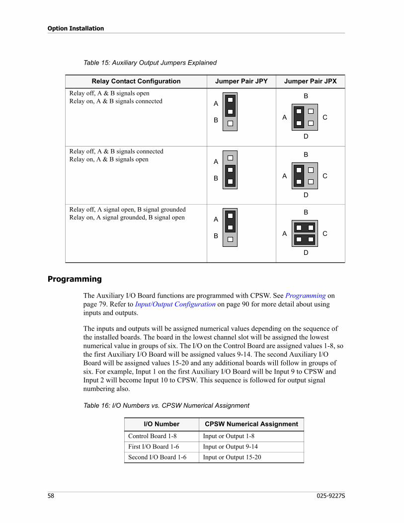
Option Installation
58 025-9227S
Table 15: Auxiliary Output Jumpers Explained
Programming
The Auxiliary I/O Board functions are programmed with CPSW. See Programming on page 79. Refer to Input/Output Configuration on page 90 for more detail about using inputs and outputs.
The inputs and outputs will be assigned numerical values depending on the sequence of the installed boards. The board in the lowest channel slot will be assigned the lowest numerical value in groups of six. The I/O on the Control Board are assigned values 1-8, so the first Auxiliary I/O Board will be assigned values 9-14. The second Auxiliary I/O Board will be assigned values 15-20 and any additional boards will follow in groups of six. For example, Input 1 on the first Auxiliary I/O Board will be Input 9 to CPSW and Input 2 will become Input 10 to CPSW. This sequence is followed for output signal numbering also.
Table 16: I/O Numbers vs. CPSW Numerical Assignment
Relay Contact Configuration Jumper Pair JPY Jumper Pair JPX
Relay off, A & B signals open Relay on, A & B signals connected
Relay off, A & B signals connected Relay on, A & B signals open
Relay off, A signal open, B signal grounded Relay on, A signal grounded, B signal open
A
B A
D
C
B
A
B A
D
C
B
A
B A
D
C
B
I/O Number CPSW Numerical Assignment
Control Board 1-8 Input or Output 1-8First I/O Board 1-6 Input or Output 9-14Second I/O Board 1-6 Input or Output 15-20

59
Model 4010 Auxiliary I/O Card
The sequence will continue for as many I/O boards as are installed.
Connector Pinout
The location of the auxiliary signals depends on which channel slot the Auxiliary I/O Board is installed in. The location will vary between output connectors as well as which half of the connector is used as shown in the following tables. First select the channel slot the Auxiliary I/O board will be installed in and that will show which connector and which half is used for the signals. The upper half or lower half then shows the appropriate pinout.
Table 17: Channel Assignment vs. Connector Pinout
Table 18: Signal vs. Pin Assignment — Upper Half
Note The locations of the Auxiliary I/O Boards are sensed during power up and are assigned the proper sequence. If an Auxiliary I/O Board is added to a channel slot before an existing board, the I/O assignment of the existing board will have to be changed via CPSW to match the new I/O numbers assigned to it by the Model 4010 software.
Channel Connector Half
1&2 (J12) J4 upper3&4 (J11) J4 lower5&6 (J10) J3 upper7&8 (J9) J3 lower9&10 (J8) J2 upper11&12 (J7) J2 lower
Signal Pin Pin Signal
open 26 1 Input 1
Analog GND 27 2 Input 2
Ground 28 3 Input 3
open 29 4 Input 4
RLY1B 30 5 RLY1A
RLY2B 31 6 RLY2A
RLY3B 32 7 RLY3A
Ground 33 8 Input 5
open 34 9 Input 6
RLY4B 35 10 RLY4A
RLY5B 36 11 RLY5A
RLY6B 37 12 RLY6A

Option Installation
60 025-9227S
Table 19: Signal vs. Pin Assignment — Lower Half
Signal Pin Pin Signal
open 38 13 Input 1
Analog GND 39 14 Input 2
Ground 40 15 Input 3
open 41 16 Input 4
RLY1B 42 17 RLY1A
RLY2B 43 18 RLY2A
RLY3B 44 19 RLY3A
Ground 45 20 Input 5
open 46 21 Input 6
RLY4B 47 22 RLY4A
RLY5B 48 23 RLY5A
RLY6B 49 24 RLY6A

61
Model 4010 Auxiliary I/O Card
Split 50 66M Type Punch-Down Block
P/N 950-9351FOUR CHANNELS UPOPEN 26 — — — — 26INPUT 1 1 — — — — 1
ANALOG GND 27 — — — — 27INPUT 2 2 — — — — 2
GROUND 28 — — — — 28INPUT 3 3 — — — — 3
OPEN 29 — — — — 29INPUT 4 4 — — — — 4RLY 1B 30 — — — — 30 Upper half for:RLY 1A 5 — — — — 5 Slot 1 (J 12)RLY 2B 31 — — — — 31 Slot 3 (J10)RLY 2A 6 — — — — 6 Slot 5 (J 8)RLY 3B 32 — — — — 32RLY 3A 7 — — — — 7
GROUND 33 — — — — 33INPUT 5 8 — — — — 8
OPEN 34 — — — — 34INPUT 6 9 — — — — 9RLY 4B 35 — — — — 35RLY 4A 10 — — — — 10RLY 5B 36 — — — — 36RLY 5A 11 — — — — 11RLY 6B 37 — — — — 37RLY 6A 12 — — — — 12
OPEN 38 — — — — 38INPUT 1 13 — — — — 13
ANALOG GND 39 — — — — 39INPUT 2 14 — — — — 14
GROUND 40 — — — — 40INPUT 3 15 — — — — 15
OPEN 41 — — — — 41INPUT 4 16 — — — — 16RLY 1B 42 — — — — 42RLY 1A 17 — — — — 17 Lower half for:RLY 2B 43 — — — — 43 Slot 2 (J 11)RLY 2A 18 — — — — 18 Slot 4 (J 9)RLY 3B 44 — — — — 44 Slot 6 (J 7)RLY 3A 19 — — — — 19
GROUND 45 — — — — 45INPUT 5 20 — — — — 20
OPEN 46 — — — — 46INPUT 6 21 — — — — 21RLY 4B 47 — — — — 47RLY 4A 22 — — — — 22RLY 5B 48 — — — — 48RLY 5A 23 — — — — 23RLY 6B 49 — — — — 49RLY 6A 24 — — — — 24
50 — — — — 5025 — — — — 25

Option Installation
62 025-9227S
Model 4010 Tone Remote System Adapter
One of the Tone Remote System Adapters (P/N 950-0255, or 950-9922) is required for the Model 4010 to transmit to a tone controlled radio. The adapter has a 2175-Hz oscillator to generate the required guard tone and has 2175-Hz filters to remove the low-level guard tone from the received audio. Only one card is required per system, which allows all channels the option of being a tone channel. The 950-0255 is a functionally equivalent replacement of the 950-9717. The 950-9922 has additional audio delay features.
Installation
The cover of the Model 4010 must be raised by unscrewing the two thumbscrews on the back of the unit and lifting the top.
The Tone Remote System Adapter is installed on the Control Board connector P4, which is near the external AUX AUDIO connector. Remove any jumpers that may be on connector P4. When installing the board, verify that the Tone Remote board pins are aligned with the Main board connector and the right angle bracket on the adapter board lines up with the mounting hole in the back panel. Secure the board by inserting the screw through the back panel hole into the bracket.
Adjustments
The Tone Remote System Adapter comes from the factory adjusted for the nominal level required by most transmitters. The guard tone level is set by the potentiometer that is labeled GT. To maintain the proper signal level between the guard tone and audio signals, the pot is set for a reading of 0.7 VP-P (-10 dB) at test point TP2, pin-6 (pin-1 is ground). The guard tone is summed with the audio at the channel card. The transmit adjustment (TX) for each channel controls the summed audio level. The difference between the high-level guard tone and the low-level guard tone is fixed at 30 dB by the channel card. The guard tone may also be monitored at the test points on the channel card, P1, but this level is dependent on the TX potentiometer setting of each channel.
Caution! Do not install this board with the power applied. Damage to the board can occur. Keep the front of the unit on the tabletop; do not let the front hang over the table edge. The console can be knocked off balance onto the floor in this position.
!
Note Test point TP2 and the notch filter jumpers are not available on 950-9717.

63
Model 4010 Tone Remote System Adapter
High Level Guard Tone Timing
The high level guard tone (HLGT) duration has a standard setting of 120 milliseconds when the channel OPT switch is in the OFF position. The HLGT duration may be selected in the system configuration when the OPT switch is in the ON position.
Notch Filters
There are four guard tone notch filters on the adapter to filter out the 2175 Hz tone from the select and unselect speaker audio, the transmitted microphone audio and the patching audio. The microphone and patching filters have jumpers to disable the filter. The default settings for the jumpers on the Tone Remote Board are to be in the IN position. Table 20 shows the jumper positions for the MIC and Patch notch filters.
Table 20: Notch Filter Jumpers on the Tone Remote Board
The notch filtering only applies to incoming audio. Although the output does not notch any guard tone frequencies that may be present, a third party notch filter can be used.
Audio Delay
The Tone Remote with Audio Delay Board (950-9922) has an additional feature, which allows for audio delay in both the Patch Bus and the MIC Bus for up to a maximum of 1.0 second.
The audio signals between the console channels that are connected together in a patching mode (Patch Bus) may be time delayed to compensate for the channel key-up time. The audio from the dispatcher (MIC Bus) may also be delayed. The two delays can be independently selected (via jumpers) and the audio delay time can be set to 0.25, 0.50, 0.75 or 1.0 second. (See Table 21). The default setting for the delay period is 0.75 seconds.
Jumper Position Status
JP6 (MIC) INOUT
Enable notch filterDisable notch filter
JP7 (Patch) INOUT
Enable notch filterDisable notch filter

Option Installation
64 025-9227S
Table 21: Delay Related Jumpers on the Tone Remote Board
When using the delay on the MIC Bus, the delayed audio will be clipped off when the transmit key is released unless a delay is programmed into the Model 4010 console configuration. The Model 4010 Console Programming System (CPSW) will have to be used to download a modified configuration. To extend the transmit time, the MIC Delay Eliminator option (Position Configuration and Audio Control menu) must be enabled (set to YES). Refer to Audio Controls on page 96 for the programming.
When the operator selects the optional Phone Patch Card, 950-9719 or 950-9720, the MIC Bus delay is automatically disabled so the sidetone back to the operator and the Select Speaker audio will not cause feedback or confusion. Firmware version 1.60 or higher is required to enable this feature.
Model 4010 DC Remote Daughter Board
The DC Remote Daughter Board (P/N 702-9380) is an option board that is installed on the Dual Channel Board. This option will allow the channel card to generate the DC current required to control DC remote controlled transmitters. Normally this option is installed at the factory, but it can also be installed in the field with the following instructions.
Installation
The cover of the Model 4010 must be raised by unscrewing the two thumbscrews on the back of the unit and lifting the top.
Remove the Dual Channel Card that has the channel that requires the DC current option. If the channel number is an odd number, the DC Remote Daughter Board is installed in
Jumper Position Status
JP1 (Delay) .25.50.751.0
0.25 second delay period0.50 second delay period0.75 second delay period1.0 second delay period
JP2 (MIC) INOUT
Enable MIC delayDisable MIC delay
JP3 (Patch) INOUT
Enable Patch delayDisable Patch delay
Caution! Keep the front of the unit on the tabletop; do not let the front hang over a table edge. The console can easily be knocked off balance onto the floor when the front hangs off the table.
!
65
Model 4010 DC Remote Daughter Board
connector P2 (upper strip connector). If the channel number is even, use connector P3. The Daughter board comes with two standoffs and mounting screws. First, remove the screws, and then install the Daughter board into the strip connector. Using the screws and standoffs, secure the board to the Dual Channel Card. Insert the Dual Channel Card into the channel slot by placing the side away from the back panel in first, then rock the card towards the back panel into position. Take care that the LEDs are properly positioned. Secure the board by inserting the screw through the hole in the back panel into the bracket on the card.
DC Current Calibration
The DC Remote Daughter Board has a potentiometer to adjust the DC current level. The pot is adjusted at the factory and should not require adjustment. The pot (R15) is accessible from the top of the unit (with Model 4010 cover open) and, with a current meter in series with the transmission line, can be adjusted to the desired level. The factory adjustment is for 0.5-milliampere programmable steps.
Programming
The Console Programming System (CPSW) is used to set the current levels for the various transmission requirements. The DC board can be programmed in 0.5-milliampere increments up to a maximum of 15 milliamperes. Refer to Channel Configuration on page 85 for details.
LOTL Option
The LOTL (line operated transmit lamp) indication is provided with the DC Remote Daughter Board. This signal is used to indicate when a transmission is occurring and to prevent the Model 4010 from transmitting while the line is busy. This signal is not useful if there is no parallel device (console or station remote) and should be disabled with the jumper on the DC board.
Note DC current levels are programmable in 0.5-milliampere steps and R15 is used only for fine adjustment.
LOTL Enabled Disable
Jumper JP1 A B

Option Installation
66 025-9227S
Model 4010 Tone LOTL Daughter Board
The Tone LOTL Daughter Board (P/N 702-9450) is an option board that is installed on the Dual Channel Board. This option will allow the channel card to monitor the transmitter line for the guard tone frequency and prevent transmission if the transmitter is busy. This option is only useful if the transmitter has a parallel device (console or station remote) controlling it.
Installation
The cover of the Model 4010 must be raised by unscrewing the two thumbscrews on the back of the unit and lifting the top.
Remove the Dual Channel Card that has the channel that requires the tone LOTL indication. If the channel number is an odd number, the Tone LOTL Daughter Board is installed in connector P2 (upper strip connector). If the channel number is even, use connector P3. The Daughter board comes with two standoffs and mounting screws. First, remove the screws, and then install the Daughter board into the strip connector. Using the screws and standoffs, secure the board to the Dual Channel Card. Insert the Dual Channel Card into the channel slot by placing the side away from the back panel in first, then rock the card towards the back panel into position. Take care that the LEDs are properly positioned. Secure the board by inserting the screw through the hole in the back panel into the bracket on the card.
The LOTL (line operated transmit lamp) signal is used to indicate when a transmission is occurring and to prevent the Model 4010 from transmitting while the line is busy. This signal is not useful if there is no parallel device (console or station remote) and should be disabled with the jumper on the board.
Caution! Keep the front of the unit on the tabletop; do not let the front hang over a table edge. The console can easily be knocked off balance onto the floor when the front hangs off the table.
LOTL Enabled Disable
Jumper JP1 A B
!
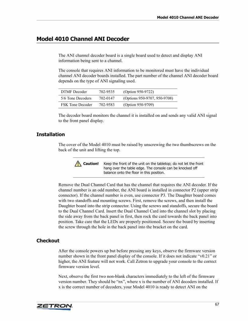
67
Model 4010 Channel ANI Decoder
Model 4010 Channel ANI Decoder
The ANI channel decoder board is a single board used to detect and display ANI information being sent to a channel.
The console that requires ANI information to be monitored must have the individual channel ANI decoder boards installed. The part number of the channel ANI decoder board depends on the type of ANI signaling used.
The decoder board monitors the channel it is installed on and sends any valid ANI signal to the front panel display.
Installation
The cover of the Model 4010 must be raised by unscrewing the two thumbscrews on the back of the unit and lifting the top.
Remove the Dual Channel Card that has the channel that requires the ANI decoder. If the channel number is an odd number, the ANI board is installed in connector P2 (upper strip connector). If the channel number is even, use connector P3. The Daughter board comes with two standoffs and mounting screws. First, remove the screws, and then install the Daughter board into the strip connector. Using the screws and standoffs, secure the board to the Dual Channel Card. Insert the Dual Channel Card into the channel slot by placing the side away from the back panel in first, then rock the card towards the back panel into position. Take care that the LEDs are properly positioned. Secure the board by inserting the screw through the hole in the back panel into the bracket on the card.
Checkout
After the console powers up but before pressing any keys, observe the firmware version number shown in the front panel display of the console. If it does not indicate “v0.21” or higher, the ANI feature will not work. Call Zetron to upgrade your console to the correct firmware version level.
Next, observe the first two non-blank characters immediately to the left of the firmware version number. They should be “nx”, where x is the number of ANI decoders installed. If x is the correct number of decoders, your Model 4010 is ready to detect ANI on the
DTMF Decoder 702-9535 (Option 950-9722)5/6 Tone Decoders 702-0147 (Options 950-9707, 950-9708)FSK Tone Decoder 702-9583 (Option 950-9709)
Caution! Keep the front of the unit on the tabletop; do not let the front hang over the table edge. The console can be knocked off balance onto the floor in this position.
!

Option Installation
68 025-9227S
appropriate channels. If the characters are “N0”, your Model 4010 did not recognize any ANI board and will not communicate with it. Make sure the ANI board is properly installed, reset the Model 4010 by cycling power, and try again. If the display still indicates “N0” or the wrong number of ANI decoders, contact Zetron.
Configuration
For ANIs to be buffered and displayed by the Model 4010, the ANI REVIEW function must be assigned to a console key (usually on the system key panel) using CPSW. Other useful functions to program are ANI SOURCE and ANI SELECT. Refer to ANI Decode/Display on page 97 for complete details.
Jumper and Switch Settings
5/6 Tone Decoder Jumpers
The jumpers JP1 and JP2 are used for 5/6 tone decoding only. The standard setting is both jumpers in position B.
FSK Tone Decoder Jumper and Switch
JP3 shorts out the incoming audio stream, disabling the ANI decode. This would normally be left open.
The SW1 4-position bitswitch is not used.
Note The Model 4010 is able to decode only the unit identification in a PTT-ID. ANIs that are configured with fleet or group designation separated by a dash from the unit ID cannot be displayed on the 4010 LCD. Therefore, end users who have multiple fleet/group IDs need to insure that the Unit IDs assigned in one fleet/group are not duplicated in another or there may be confusion as to the source of the call.
JP1 JP2 ZVEI Formats (950-9707)
B B ZVEI where repeat digit = 2600 HzB A DZVEI where repeat digit = 2400 HzA B ZVEI-2 where repeat digit = 970 HzA A Ignore ANIs
JP1 JP2 CCIR Formats (950-9708)
B B CCIR/EEAB A Ignore ANIsA B Ignore ANIsA A Ignore ANIs

69
Model 4010 Parallel Status Option
Model 4010 Parallel Status Option
When two Model 4010 consoles control the same radio transmitter, the Parallel Status Option communicates the frequency information between the consoles. The Busy Out and Busy In signals of the two associated channels also need to be connected together so the consoles reflect the transmit status of the channel.
The Parallel Status Option has the following features and limitations:• Two consoles can be connected together for parallel status• This option cannot be used on a console with an expansion panel installed• Only frequency switching information is shared
Cable Installation
A split 50 terminal 66M punch-down block can be used for the installation. It allows the channel signals from the two consoles to be brought to adjacent pins. Jumpers or bridge clips can then be used to connect PTT-, PTT+, Tx-, Tx+, Rx-, and Rx+ (if 4-wire) of the two channels. The Busy Out signal must be connected to the Busy In of the associated channel of the second console and the Busy In to the associated Busy Out. See Figure 10 for the split 50-block configuration.
The parallel status cable (P/N 709-7313) is installed between the two consoles’ Data Comb connectors (6 pin RJ-11). This cable transfers the frequency information between consoles.
Channel Card Termination
When connecting two consoles to the same transmitter, only one console can be terminated with 600 ohms impedance. The second should be in the high impedance configuration. The console that is the longest distance from the transmitter should have the 600 impedance. See Table 22 for the Model 4010 channel card jumper positions for the impedance settings.
Table 22: Channel Card Impedance Jumper Settings
Option Channel A Channel B
2-Wire Line Termination Low Impedance (600 Ω)High Impedance (3.5 kΩ)
JP1-AJP1-B
JP7-AJP7-B
4-Wire Line Termination Low Impedance (600 Ω)High Impedance (10 kΩ)
JP2-AJP2-B
JP3-AJP3-B

Option Installation
70 025-9227S
Console Programming
The console must be programmed using the Console Programming System (CPSW) to enable the Parallel Status option. If the console is ordered with the Parallel Status option, it is programmed at Zetron. Refer to Miscellaneous on page 99 for programming information.

71
Model 4010 Parallel Status Option
Figure 10: Split 50 66M Punch-Down Block (P/N 950-9351) for the Parallel Status Option FOUR CHANNELS Chan A. PTT - 26 — — — — 26 Chan A. PTT -Chan A. PTT + 1 — — — — 1 Chan A. PTT +
Analog GND 27 — — — — 27 Analog GNDChan A. Record 2 — — — — 2 Chan A. Record
Ground 28 — — — — 28 GroundChan A. Aux Output 3 — — — — 3 Chan A. Aux OutputChan A. TX - 29 — — — — 29 Chan A. TX -Chan A. TX + 4 — — — — 4 Chan A. TX +Chan A. RX - 30 — — — — 30 Chan A. RX -Chan A. RX + 5 — — — — 5 Chan A. RX +Chan A. X-Busy Out 31 — — — — 31 Chan A. X-Busy OutChan A. X-Busy In 6 — — — — 6 Chan A. X-Busy InChan B. PTT - 32 — — — — 32 Chan B. PTT -Chan B. PTT + 7 — — — — 7 Chan B. PTT +
Analog GND 33 — — — — 33 Analog GNDChan B. Record 8 — — — — 8 Chan B. Record
V+ 34 — — — — 34 V+Chan B. Aux Output 9 — — — — 9 Chan B. Aux OutputChan B. TX - 35 — — — — 35 Chan B. TX -Chan B. TX + 10 — — — — 10 Chan B. TX +Chan B. RX - 36 — — — — 36 Chan B. RX -Chan B. RX + 11 — — — — 11 Chan B. RX +Chan B. X-Busy Out 37 — — — — 37 Chan B. X-Busy OutChan B. X-Busy In 12 — — — — 12 Chan B. X-Busy InChan C. PTT - 38 — — — — 38 Chan C. PTT -Chan C. PTT + 13 — — — — 13 Chan C. PTT +
Analog GND 39 — — — — 39 Analog GNDChan C. Record 14 — — — — 14 Chan C. Record
Ground 40 — — — — 40 GroundChan C. Aux Output 15 — — — — 15 Chan C. Aux OutputChan C. TX - 41 — — — — 41 Chan C. TX -Chan C. TX + 16 — — — — 16 Chan C. TX +Chan C. RX - 42 — — — — 42 Chan C. RX -Chan C. RX + 17 — — — — 17 Chan C. RX +Chan C. X-Busy Out 43 — — — — 43 Chan C. X-Busy OutChan C. X-Busy In 18 — — — — 18 Chan C. X-Busy InChan D. PTT - 44 — — — — 44 Chan D. PTT -Chan D. PTT + 19 — — — — 19 Chan D. PTT +
Analog GND 45 — — — — 45 Analog GNDChan D. Record 20 — — — — 20 Chan D. Record
V+ 46 — — — — 46 V+Chan D. Aux Output 21 — — — — 21 Chan D. Aux OutputChan D. TX - 47 — — — — 47 Chan D. TX -Chan D. TX + 22 — — — — 22 Chan D. TX +Chan D. RX - 48 — — — — 48 Chan D. RX -Chan D. RX + 23 — — — — 23 Chan D. RX +Chan D. X-Busy Out 49 — — — — 49 Chan D. X-Busy OutChan D. X-Busy In 24 — — — — 24 Chan D. X-Busy In
Chassis 50 — — — — 50 ChassisChassis 25 — — — — 25 ChassisCONSOLE 1 CONSOLE 2

Option Installation
72 025-9227S
GE-Star Decoder
The ZETRON Model 4010 GE-STAR Decoder is designed to add on to any existing ZETRON Model 4010 Dual Channel Card. The GE-STAR Decoder can be configured to interpret one of a number of different GE-STAR formats. The DIP switches 1-4 on the GE-STAR Decoder board determine the format that will be decoded. Each format uses the GE-STAR T1, T2, and S1 bits in a different manner and some formats expand the basic 11-bit GE-STAR ID.
GE-STAR Overview
The signaling method used in GE-STAR is phase-shift-keying (PSK). This method uses 400 bps data with a 1600 Hz sub-carrier, resulting in 90 degree phase shifts that indicate a change in bit status (either 0 to 1 or 1 to 0).
The format of the data is shown below:-------------------------------------------------
Word 1: | | | | | |11|10| 9| 8| 7| 6| 5| 4| 3| 2| 1|-------------------------------------------------
^ ^Sync Bits ID Bits
-------------------------------------------------Word 2: |T1|T2|S1|S2|S3|S4|M1|M2|M3|M4| | | | | | |
-------------------------------------------------^ ^ ^ ^Tag Status Message ErrorBits Bits Bits Detection Bits
Typically, the GE-STAR information is transmitted in a short burst of three repeated messages of the above format, preceded by a 16-bit preamble of alternating l’s and 0’s. The repetitions and error detection on each message provide immunity to falsing and high decoding reliability.
GE-STAR Decoder Setup
DIP switches 1-4 on the Model 4010 GE-STAR Decoder board determine the format that will be decoded. The valid settings are summarized below:
Table 23: Multi-System Formats (T1,T2=System Number)
Switches4321 Description
0000 System 0 Only Decode0001 System 1 Only Decode0010 System 2 Only Decode0011 System 3 Only Decode
0=On (direction of arrow on switch)1=Off (opposite direction of arrow on switch)

73
GE-Star Decoder
Table 24: Mobile/Portable Formats (T2=O=Mobile, T2=1=Portable)
Table 25: Extended ID Formats
Switch settings other than those listed above will default to 11-bit ID decoding, ignoring the T1, T2, and S1 bits of the GE-STAR receive information.
Error Indications
If the GE-STAR Decoder receives and decodes an ANI that is out of the 0000-9999 range, it will display “#####” on the console to indicate the error. Any emergency or man-down indications will be passed to the console also, despite the out of range ID.
Output Format
The M4010 ZETRON GE-STAR Decoder output will display on the console as a sequence of characters and numbers that represent the decoded GE-STAR ID. The displayed ID starts with either a number sign (#) for non-emergency ID’s or a star (*) for emergency IDs, followed by the four digit ID number (0000-9999), followed by a status or message character if present in the transmission. The possible outputs are shown below:
Switches4321 Description Extra ID Bits
0110 12-bit Mobile/Portable T1=12th bit0111 13-bit Mobile/Portable S1=12th bit, T1=13th bit
0=On (direction of arrow on switch)1=Off (opposite direction of arrow on switch)
Switches4321 Description Extra ID Bits
1101 GE-STAR #4 T1=13th, T2=12th, S1=14th1110 GE-STAR #3 T1=13th, T2=14th, S1=12th1111 Expanded- ID STAR #1 T1=14th, T2=13th, S1=12th
0=On (direction of arrow on switch)1=Off (opposite direction of arrow on switch)

Option Installation
74 025-9227S
Table 26: 11-Bit and Extended ID Decoding
Table 27: Mobile /Portable Decoding
Table 28: Multi-System Decoding
Output Description
#xxxxS Status Message (where S=0-7)#xxxxB Request to Talk ID#xxxxC Stuck Mic ID#xxxx PTI ID*xxxx Emergency ID*xxxxD Man Down IDwhere xxxx = decoded GE-STAR ID:
0000-2047 w/11-bit decoding0000-4095 w/12-bit decoding0000-8191 w/13-bit decoding0000-9999 w/14-bit decoding
Output Description
#xxxx*(S) Mobile Decode (S=Status, if any)#xxxx#(S) Portable Decode (S=Status, if any)
Output Description
#xxxx(S) Decoded for system 0, 1, 2, or 3 only (S=Status, if any)
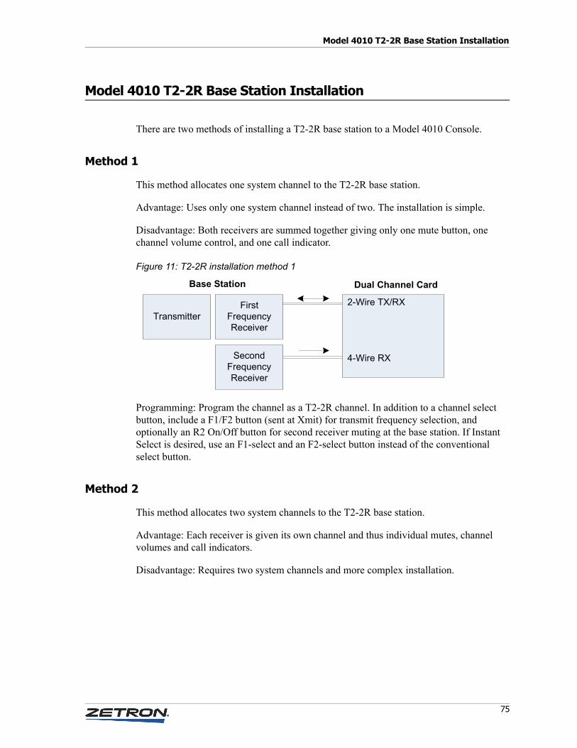
75
Model 4010 T2-2R Base Station Installation
Model 4010 T2-2R Base Station Installation
There are two methods of installing a T2-2R base station to a Model 4010 Console.
Method 1
This method allocates one system channel to the T2-2R base station.
Advantage: Uses only one system channel instead of two. The installation is simple.
Disadvantage: Both receivers are summed together giving only one mute button, one channel volume control, and one call indicator.
Figure 11: T2-2R installation method 1
Programming: Program the channel as a T2-2R channel. In addition to a channel select button, include a F1/F2 button (sent at Xmit) for transmit frequency selection, and optionally an R2 On/Off button for second receiver muting at the base station. If Instant Select is desired, use an F1-select and an F2-select button instead of the conventional select button.
Method 2
This method allocates two system channels to the T2-2R base station.
Advantage: Each receiver is given its own channel and thus individual mutes, channel volumes and call indicators.
Disadvantage: Requires two system channels and more complex installation.
TransmitterFirst
Frequency Receiver
Second Frequency Receiver
2-Wire TX/RX
4-Wire RX
Base Station Dual Channel Card

Option Installation
76 025-9227S
Figure 12: T2-2R installation method 2
Programming: Program both channels A and B as Custom channels. When asked for the custom tone or current, specify the value that is desired. Generally, channel A will have an F1 tone (1950 Hz) or current (+5 mA), and Channel B will have an F2 tone (1850 Hz) or current (+12.5 mA) upon transmit only.
TransmitterFirst
Frequency Receiver
Second Frequency Receiver
2-Wire TX/RX
Channel B(F2 RX)
4-Wire RX (see note)
Busy OutputBusy/Mute Input
Busy OutputBusy/Mute Input
2-Wire TX/RX
Channel A(F1 RX)
4-Wire RXNo
Connection
Channel B Configuration:2-wire termination = low impedanceConfiguration switch 2 (x-mute) = On
Channel A Configuration:2-wire termination = high impedanceConfiguration switch 6 (x-mute) = On
Base Station Dual Channel Card
Note In the configuration shown in Figure 12, the 2-wire Rx in Channel B should be turned down (CCW) so that F1 RX 2-wire audio is not processed on Channel B.

77
PTT Handset with Cradle
PTT Handset with Cradle
The PTT Handset (P/N 950-9315) may be used with the Model 4010 Console. When installed in the field, the handset cradle must be mounted to the side of the console using the four mounting holes provided. See Figure 13 for details.
The connector with wires from the switch hook is installed on P3, which is on the Control Board under the handset cradle mounting location. The four-wire modular cord from the handset is installed in the modular connector on the exterior side of the console near the handset cradle.
Figure 13: Handset Cradle Assembly
2 PLCS
6 7
TO P3
10 PLCS2
1. 8
5
4
INSTALL PINS AND HOUSING ON OTHER END OF WIRES.EACH WIRE TO HOOKSWITCH TERMINALS AS SHOWN.
1. CUT WIRE INTO 2 6" PIECES. SOLDER ONE END OF
11
NOTES:
ITEM QTY. PART NUMBER DESCRIPTION
1 2 220-0200 SCREW, 6-32x1", PAN, PHL, S-Zn
4 2 234-0017 WASHER, STAR, #8, CTSK, SS3 2 234-0011 WASHER, LOCK, SPLIT, #4, S-Zn
7 1 401-0083 CONN,CRIMP TERM HOUSING,2 POS6 2 401-0082 CRIMP TERM5 2 251-3473 SPACER,RND,#8x1/2",.25"OD/.171"ID
11 1 802-1078 UNIVERSAL HOOKSWITCH10 1 802-0097 HANDSET, PTT9 1 709-0002 HANDSET CORD, 4-WIRE8 12" 408-2201 WIRE, 22AWG (19x34) PVC, WHITE
2 PLCS
ON CONTROLLER BOARD
2 PLCS
MODEL 4010 CHASSISVIEWED FROM REAR
PART OF802-1078
1
2. DISCARD PANHEAD SCREWS (2), LOCKWASHERS (2),AND HEX STANDOFFS SUPPLIED WITH 802-1078.
2 10 234-0006 WASHER, FLAT #6 STEEL ZINC3 2 PLCS

Option Installation
78 025-9227S

Introduction
79
Programming
Introduction
This chapter describes how to use the Console Programming System for Windows (CPSW). CPSW provides technicians with the ability to field program any of the keys on a Model 4010, Model 4116B, Model 4018, or Model 4118. The keys may be defined to accommodate a new channel, a new layout, or a new remote function. The advanced menu-driven window interface makes the program intuitive and easy to use.
The CPSW executable can be run to support the Model 4010, or the Model 4116B and 4018/4118. This chapter provides instruction for CPSW for the Model 4010 only. The following table can help you identify the correct documentation for your model.
Versions and Compatibility
DOS and Windows
CPSW replaces CPS, an older program with similar functionality but created for use in MS-DOS. The older CPS application may be used within a command line window on a
Model Manual
M4010 Model 4010 Radio Dispatch Console Installation (this manual)P/N 025-9227
M4116BM4018M4118
Series 4000 Installation and Configuration ManualP/N 025-9533 (rev F or newer)
Tip For online help, press F1 at any time in the CPSW application.

Programming
80 025-9227S
Windows 95, 98, ME, or XP Professional PC as long as the serial port settings are set to: 9600, N, 8, 1, no flow control.
Firmware Compatibility
Each version of CPS and CPSW is designed to work with a specific firmware version or range of firmware versions. It is best to use the version of CPSW that was delivered with your system or your last firmware upgrade. If you need a replacement copy of CPSW, contact Zetron technical support. They can assist you with acquiring the correct programming software for your specific firmware.
• CPS is supported for firmware versions up to 1.80 only.• CPSW is supported for firmware versions 1.80 and newer.
Installation
Installation
To install CPSW, follow the instructions provided with it (CPSW Installation Notes, P/N 011-0795).
Uninstallation
♦ To uninstall CPSW
CPSW uses the standard Windows procedure for uninstallation.1. From the Windows Control Panel, double-click Add/Remove Programs.2. In the alphabetical list of installed programs, find and click Zetron CPSW to
select it.3. With Zetron CPSW selected, click Remove (located on the same highlighted
line).4. Proceed through the uninstallation wizard.
Tip This chapter is for CPSW only. CPS DOS users can obtain the CPS manual (025-9229 Model 4010 Programming) by contacting Zetron or by directly downloading from the Zetron reseller website. See http://www.zetron.com.
Note The Microsoft .NET Framework can also be uninstalled using the same method, but this is not recommended because other applications may rely on .NET.

81
CPSW Menu Structure
CPSW Menu Structure
The following two figures provide a map for all menu items in CPSW. Figure 14 shows all menus items except key definitions. Figure 15 shows menu items related to key definitions.
Figure 14: CPSW Menu Structure
Note When using CPSW, several menu items may be unavailable if they are incompatible or not relevant based on other configured settings. For example, keys cannot be defined for custom channel functions if there are no custom channels in the current system configuration.
M4010 CPSW
EditFile
Channel ConfigurationPaging Format ConfigurationEdit Custom CallsInput/Output ConfigurationTx Timeout
Priority Marker FrequencyPriority Marker DurationPriority Marker IntervalPriority Marker Amplitude
No Control Type Selected
Local (E&M) ControlTone ControlDC Control-ConstantDC Control-Momentary DC Control Protocol T1R1 STD
T1R1 PagingT2R2 / T22RT4R4Custom
T1R1 without PagingT1R1 with PagingT2R2/T22R without PLT2R2/T22R with PLT4R4 without PLT8R8Custom
Tone Control Protocol
Key Definitions Miscellaneous
Audio Source for Soft Tx
Parallel Remote Status
Instant Select Key Display ModeReceived Call Light Duration
Dynamic MicElectret MicSpare Input #9Hookswitch Steers
Display Operation
Dashes12-Hour Time24-Hour Time
Position Layout
Panel 2
ANI Decode/Display
Operating ModeUnmute Channel Upon Receiving ANI
Communication Help
Recieve config from PositionSet Serial Port
Send config to Position Contents and IndexAbout CPSWOpen
Save
New
Exit
Save AsTo FileTo PrinterPrint
System ConfigurationSystem and Position
Position Configuration
Priority Marker
Panel 3
DestinationEmergency ANI Acknowledge
Audio Controls
Muted Audio LevelMinimum Audio LevelDefault Volume LevelSpeaker Mute While TxMute All Idle Channels
Mute Signaling TonesMic Delay Eliminator Enable
Unmute Idle Chan Upon MonitorDynamic Mic selection Desk Mic
Gooseneck Mic
FlashesSolid
I/O Card 1
Primary AddressSecondary AddressTimeout Period
Channel NameChannel TypeKeyup DelayInter Stack DelayDe Emphasis Enabled
Chan. Mon Fnctn DC Ctrl CurrentPage Function DC Control Current
Chan. Monitor Function Tone FreqPaging Function Tone Freq
Next page
System Configuration
Position Configuration
No ANI DisplaySelected ChannelsAll Channels
System ConfigurationSystem and Position
Position Configuration
I/O Card 2I/O Card 3I/O Card 4I/O Card 5
Main
Custom HLGT Duration
Telephone Control
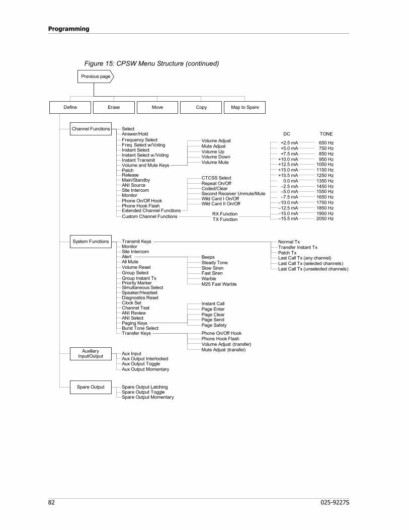
Programming
82 025-9227S
Figure 15: CPSW Menu Structure (continued)
Erase Move Copy Map to SpareDefine
Select
Frequency SelectFreq. Select w/VotingInstant SelectInstant Select w/VotingInstant TransmitVolume and Mute KeysPatch
Main/StandbyANI SourceSite IntercomMonitorPhone On/Off HookPhone Hook Flash
Transmit Keys
AlertAll Mute
Group Instant TxPriority Marker
ANI ReviewANI SelectPaging Keys
Phone On/Off HookPhone Hook FlashVolume Adjust (transfer)Mute Adjust (transfer)
Instant CallPage EnterPage ClearPage SendPage Safety
BeepsSteady ToneSlow SirenFast SirenWarbleM25 Fast Warble
Normal TxTransfer Instant TxPatch TxLast Call Tx (any channel)Last Call Tx (selected channels)Last Call Tx (unselected channels)
MonitorSite Intercom
Burst Tone Select
Wild Card II On/Off
CTCSS SelectRepeat On/OffCoded/ClearSecond Receiver Unmute/MuteWild Card I On/Off
DC TONE
Spare Output MomentarySpare Output ToggleSpare Output Latching
Volume AdjustMute AdjustVolume UpVolume DownVolume Mute
Custom Channel Functions
Volume ResetGroup Select
Channel TestClock SetDiagnostics ResetSpeaker/HeadsetSimultaneous Select
Transfer Keys
Channel Functions
System Functions
Extended Channel Functions
AuxiliaryInput/Output
Spare Output
Aux Output MomentaryAux Output ToggleAux Output InterlockedAux Input
Previous page
RX FunctionTX Function
+2.5 mA+5.0 mA+7.5 mA
+10.0 mA+12.5 mA+15.0 mA+15.5 mA
0.0 mA–2.5 mA–5.0 mA–7.5 mA
–10.0 mA–12.5 mA–15.0 mA–15.5 mA
650 Hz750 Hz850 Hz950 Hz
1050 Hz1150 Hz1250 Hz1350 Hz1450 Hz1550 Hz1650 Hz1750 Hz1850 Hz1950 Hz2050 Hz
Answer/Hold
Release
83
CPSW Menu Structure
Using CPSW
This chapter describes how to configure Model 4010 dispatch consoles. This is accomplished through three primary tasks:
1. Use one of the following methods to get configuration settings:a. Download an existing configuration from a console
(see To receive the configuration from a console on page 84)b. Open an existing configuration file from a disk
(see To load a configuration from a file on page 84)c. Start with a new, blank configuration
(see To configure a position’s panel layout on page 94)2. Edit the configuration settings as needed
(see Editing a Configuration on page 85)3. Save the configuration file and send the configuration to one or more consoles
(see Sending a Configuration to a Console on page 101)
This section, Using CPSW, provides step-by-step procedures to cover everything you need to do in order to configure your consoles.
Starting CPSW
Start CPSW by double-clicking on its shortcut. Alternatively, the program itself is located in C:\Program Files\Zetron\CPSW\ and titled “CPSW_Application.exe” (assuming the default location was used during installation). If you don’t use the shortcut, CPSW will prompt you for the system type, which is M4010.
Configuring CPSW
The serial port setting is the only setting needed to configure the CPSW application. By default, CPSW is set to COM1.
♦ To configure the serial port
1. Determine which serial port will be used to connect to consoles (typically COM1 or COM2).
2. Go to Communication, Set Serial Port.3. CPSW provides a list of available COM ports. Select the serial port to use.4. Click Save Port Selection.
Loading a Configuration
Zetron uses CPSW to preconfigure Model 4010 consoles for customers. The resulting configuration file is supplied by email or floppy disk to customers.

Programming
84 025-9227S
♦ To receive the configuration from a console
1. Use the supplied programming cable to connect your PC with the console:• If you have a cable with one RJ connector (P/N 709-7266 or 709-7400), use it
to connect the serial port of your computer to the COMB jack (combined data) on the console.
• If you have a cable with two RJ connectors (P/N 709-7084 or 709-7417), use it to connect the serial port of your computer to the DATA IN and DATA OUT jacks on the console (these jacks might also be named LOOP IN and LOOP OUT). The cable ends are labeled for specific ports (IN vs OUT) and must be connected correctly.
If there are existing cables already connected to any of these ports, you must temporarily remove them while programming. Before removing these existing cables, ensure they are labeled so they can be returned to the proper ports.
2. There is an unlabeled switch on the bottom of the Model 4010 used to switch the console between RUN and PROGRAM modes. Move the switch to the program position, which is towards the gooseneck MIC and away from the DATA IN, DATA OUT, and COMB jacks.The console display shows “PROGRAM”.
3. In CPSW, click Communication, Receive config from Position.4. Click OK to begin receiving the configuration.
The console display shows “UpLoading CPS” while it is sending data and shows “DONE” when all data is transferred.If you receive the error message “Console did not send any data”, check the following items and try again:
• Check your cable for loose or incorrect connections• Ensure the RUN/PROGRAM switch is set to PROGRAM• Check your serial port settings (see To configure the serial port on page 83)
♦ To load a configuration from a file
1. Click File, Open.
Note The USB-to-serial port adapter provided by Zetron (P/N 802-0516) is tested and the recommended adapter for this application. Many third party USB-to-serial port adapters are inconsistent with their serial port implementation and do not reliably communicate with Zetron equipment.

85
CPSW Menu Structure
2. Navigate to the location containing your configuration files. Configuration files have a file name extension of “.cf1”. The default location is C:\CPSW Config Files\.
3. Double-click the appropriate .cf1 file.Once loaded, the system name of this configuration appears in the window’s title bar adjacent to “CPSW” and the CPSW version number. When ZETRON prepares the configuration file, the system name is also the first seven letters of the filename.
Editing a Configuration
There are two types of configuration settings: position and system. Position configuration refers to the settings specific to a single console position, such as the button layout and preferences for that position. System configuration refers to overall system settings such as channel types, paging formats, and I/O.
System Settings
Channel Configuration
♦ To configure channels
1. Click Edit, System Configuration, Channel Configuration.2. Select the channel number to configure using the up and down arrows next to
Channel Number.3. Enter a Channel Name. Channel Name is used for reference only, and can be left
blank if desired.
Note CPSW configuration files ending in “.cf1” are used for M4010 and M4010R consoles.
CPSW files ending in “.cfg” are used for M4x18 (Series 4000) consoles.
Tip If custom configuration files were provided by Zetron, they are located on the supplied 3.5” floppy disk.
Warning! Prior to configuring the system, it is imperative that the programmer has a complete understanding of the radio system that is to be controlled by the Model 4010 console.
STOP
Tip It is best to configure system settings before position settings. Some position settings, such as specific key definitions, are not available until the system settings are configured correctly.

Programming
86 025-9227S
4. Select the Channel Type.
5. If applicable, select the Control Protocol. Some channel types have control protocols and some do not. Also, the list of available control protocols will vary depending on channel type.
Channel Type Description
DC Control Momentary
Use this DC control option if the radio requires only a momentary DC current to perform the desired function.
DC Control Constant
Some radios require that the control current be maintained constant in order to perform the desired function. Use this option if your radio requires a constant current.
Tone Control Radio is controlled by way of various tone frequencies.Local (E&M) Control
A local control radio has only PTT and audio connections; it does not have control functions.
Telephone Control
Due to slot/card compatibility, channels 13 and 14 can only be Telephone Control. No other channels can be Telephone Control.
Note Different channel types have different settings to be configured. Depending on the channel type you have configured, some of the following settings may not be relevant and available for configuration.
Note Channels 13 and 14 are only supported by the Phone Patch Interface Card. Therefore, the only compatible channel type for those channels is Telephone Control.
Control Protocol Description
T1R1Without Paging
Single frequency standard tone controlled radio without paging option. This is the option to use if the channel is to be used without an external paging terminal such as a Model 25.
T1R1With Paging
Single frequency standard tone controlled radio with external paging option. If your radio supports the paging option, use this type. The Auxiliary PTT input will cause a control tone different from the normal PTT to be generated.
T2R2/T22R Without PL
Two-frequency tone controlled remote radio without PL. Refer to DC and Tone Remote Function Definitions on page 110 for a list of the frequencies generated.
T2R2/T22R With PL
Two-frequency standard tone controlled radio with Private Line (PL)-Tone Squelch option. If your radio supports the PL option, use this type. The Auxiliary PTT input will cause a control tone different from the normal PTT to be generated.

87
CPSW Menu Structure
6. If applicable, select the DC Control Current or Tone Frequency used for channel monitor. See DC and Tone Remote Function Definitions on page 110 for a description of the control currents and tone frequencies.The options for channel monitor depend upon the channel type and some channel types may not support a monitor function at all.
7. If applicable, enter a value from 0.0 to 10.0 seconds for Keyup Delay to set the time delay between when the channel has finished keying up the transmitter and the start of the first page in a stack.
8. If applicable, enter a value from 0.0 to 10.0 seconds for Inter-Stack Delay to set the time delay between pages in a stack. This delay will only occur for manually entered page stacks (i.e., for two or more pages entered via Paging/DTMF keypad). Because each page can be sent out over different channels, Instant-Call (single button) paging stacks always use the Keyup Delay between pages even if the next page uses the same channel as the previous page.
9. If applicable, select the DC Control Current or Tone Frequency used for paging function. See Appendix B: CPSW Reference Material on page 109 for a description of the control currents and tone frequencies.The options for channel monitor depend upon the channel type and some channel types may not support a monitor function at all.
10. If applicable, enable or disable De Emphasis by marking or clearing its checkbox. De Emphasis may need to be enabled if the radios transmitting via the console are using Pre Emphasis. If you are uncertain, leave De Emphasis disabled.
11. If you have additional channels to configure, click Next or Previous and repeat this procedure.
12. If you are finished configuring channels for now, click Done.
♦ To delete or clear a channel’s configuration
1. There are two ways to delete a channel’s configuration:a. If you want to delete a channel’s configuration but retain the channel name,
change the Channel Type to No Control Type Selected.b. If you want to delete a channel’s configuration including the channel name,
click Delete or change the Channel Type to Undefined.
T4R4Without PL
Four-frequency tone controlled remote radio without PL. Refer to DC and Tone Remote Function Definitions on page 110 for a list of the frequencies generated.
T8R8 This is an eight-frequency tone controlled remote radio. Refer to DC and Tone Remote Function Definitions on page 110 for a list of the tones required to control this type of radio.
Control Protocol Description

Programming
88 025-9227S
Paging Format Configuration
Each paging format to be used in Model 4010 consoles must have certain parameters unique to that format defined and must have a leading digit assigned to it. There are 14 leading digits available to be assigned among the nine different paging formats the console is capable of generating (some of which are optional). This allows the console user to select which type of page to transmit by preceding each page with its assigned leading digit.
If only one paging format is programmed (only one leading digit has been assigned), the page is keyed in directly and no leading digit is necessary (or allowed). The console already knows what type of page it will be.
Multiple variations of the same paging format can be programmed into the console by assigning each one its own unique leading digit. For example, leading digits 3, 4, and 5 might each be assigned to the DTMF paging format but with different on/off timing defined for each of the three formats.
♦ To assign and configure a paging format for a leading digit
1. Click Edit, System Configuration, Paging Format Configuration.2. To select a leading digit to configure, click on the leading digit or click Prev. Digit
/ Next Digit until it is selected.3. Select the Paging Format.
A number of configurable settings are displayed based upon the paging format that was selected.
4. Configure the paging format settings. In general, you need to match your particular or desired radio setup.Notes for certain paging formats:a. Most paging formats have a setting for Talk Time that may need to be
configured. Talk Time is the default amount of time after a page is finished that the microphone and transmitter are keyed up. After that time expires, the next page in the stack is transmitted.Operators can use the Transmit key or a PTT button to override the default Talk Time by extending or cancelling the transmission. Once the Transmit key or a PTT button is pressed, the default Talk Time is cancelled and the transmitter is keyed up until the key or button is released.
b. If you are using the paging format “1000 Call Two Tone” or “100 Call Two Tone”, the details for the code plans are listed in Appendix B: CPSW Reference Material on page 109.
c. If you are using the paging format “Custom (Plectron)” be sure to later configure custom calls (see To configure Custom Calls on page 90).
Note When programming Instant Call Key paging stack(s), a leading digit is always required.

89
CPSW Menu Structure
d. The paging format “Alerts” is used to add various alert tones to your pages. The following list shows the page character used by the operator to generate each Alert function:(0) Beep alert(D) Delay function(1) Slow siren alert(2) Fast siren alert(3) Hi/Lo warble alert(4) Fast warble alertFor example, assuming the “Alerts” paging format has been assigned to leading digit “A”, keying A4 on the Model 4010 paging/DTMF keypad enters the Fast Warble alert on the paging stack.Beep Alert (0) and Delay (D) function are configurable:
• Tone Frequency configures the tone for the Beep Alert. (When programming a delay, you must use a frequency even though no tone is being processed.)
• ON Duration sets the length of each beep tone.• OFF Duration sets the delay between each beep tone.• Count / Delay Time sets the number of beeps for the Beep Alert or the
delay in seconds for the Delay function.The tones for Alert (1) through (4) are predefined in the console; only their duration is configurable (by setting Alert Duration).
5. If you have additional Leading Digits to assign, repeat this procedure. If you are finished, click Done.
Edit Custom Calls
Custom Calls defines your own custom two-tone pages for the paging format “Custom (Plectron)”. If you have assigned a leading digit to a custom paging format (see To assign and configure a paging format for a leading digit on page 88), then you must configure custom calls here.
Warning! When you have configured a Leading Digit and you select another Leading Digit, the configuration changes you made are automatically applied. Clicking Cancel only cancels configuration changes for the currently selected Leading Digit. Likewise, clicking Revert only reverts configuration changes for the currently selected Leading Digit.
Note The “Edit Custom Calls” menu item is only enabled when there is a leading digit in the “Paging Format Configuration” dialog that has been defined as “Custom (Plectron)”. Otherwise, this menu item is disabled and cannot be accessed to configure any data in the area.
STOP

Programming
90 025-9227S
♦ To configure Custom Calls
1. Click Edit, System Configuration, Edit Custom Calls.If the Edit Custom Calls menu item is disabled, you must first assign a leading digit to a custom paging format (see To assign and configure a paging format for a leading digit on page 88).
2. Type in a custom Call Number between 1 and 255 and press Enter. Alternatively, you can select a call number by using the Up and Down arrow controls or the Next and Prev buttons.Choose a Call Number based on the number to key in. For example, if the “Custom Call” paging format has been assigned to leading digit “C” and you configure Call Number “11”, then keying “C11” on the Model 4010 paging/DTMF keypad would add the custom call to the paging stack.
3. If you are configuring a call number that wasn’t previously defined, click Define to make the Tone Settings editable. (If the call number was previously defined, the Tone Settings are already editable.)
4. Enter the Frequency and Duration parameters for each tone, the Tone Gap Duration (duration between tones 1 and 2), and the Talk Time. For an explanation of Talk Time, see Step 4 on 88.
5. If you have additional Call Numbers to configure, repeat this procedure. If you are finished, click OK.
♦ To delete custom calls
1. To delete all custom calls, click Delete All Custom Calls.2. To delete a specific custom call:
a. Select the Call Number to be deleted.b. Click Delete.
Input/Output Configuration
The main board of the Model 4010 is equipped with eight inputs and outputs. These inputs and outputs can be used as auxiliary inputs and outputs, or as spare inputs and outputs. All inputs on the board must be one or the other (auxiliary or spare). All outputs must be one
Tip The defined buttons jump to the next or previous defined call numbers only, thus skipping undefined call numbers.
Tip The Revert button will restore the settings of the current call number only. The settings for other call numbers are not affected.
91
CPSW Menu Structure
or the other (auxiliary or spare). Different types of inputs and outputs serve different purposes.
• Auxiliary inputs are limited to controlling the console LED indicators. These are typically used to monitor alarms or show voter status.
• Spare inputs can control console LED indicators and can also be associated with function keys. For example, spare inputs can perform configurable functions, such as selecting a channel or transmitting.
• Auxiliary outputs can be interlocked with other auxiliary outputs and associated with auxiliary inputs. Auxiliary outputs have more choices than spare outputs when configuring the LED behavior. There are up to 38 auxiliary outputs available, so they can be labeled in CPSW for reference purposes.
• Spare outputs cannot be interlocked, associated with inputs, or labeled. Spare outputs have less choices for LED configuration. Spare outputs 7 and 8 can be used for a special purpose related to ANI. See Outputs 7 and 8 in Reverse Selective Calling Mode on page 129.
• The eight inputs on the main board can be configured to be all spares or all auxiliary. Likewise, the eight outputs on the main board can be configured to be all spares or all auxiliary.
• The number of auxiliary inputs and outputs can be increased by adding Aux I/O Cards (see Model 4010 Auxiliary I/O Card on page 56). Each Aux I/O Card has six inputs and six outputs, and you can add up to five Aux I/O Cards. For more information about auxiliary inputs and outputs, see Auxiliary Input/Output on page 128.
• There is no method for adding more spare inputs and outputs.
♦ To configure the main board I/O as spare or auxiliary
1. Click Edit, System Configuration, Input/Output Configuration.2. To configure the inputs as auxiliary, mark the Use Control Board Spare Inputs as
Aux Inputs checkbox.3. To configure the inputs as spare, clear the Use Control Board Spare Inputs as
Aux Inputs checkbox.4. To configure the outputs as auxiliary, mark the Use Control Board Spare
Outputs as Aux Outputs checkbox.5. To configure the outputs as spare, clear the Use Control Board Spare Outputs as
Aux Outputs checkbox.
Tip You will have to make choices about whether you need spare or auxiliary inputs and outputs before you configure them. Therefore, you should read about and understand the differences provided in the following list before you start configuration procedures.
Programming
92 025-9227S
6. Proceed with the following procedure to label auxiliary I/O, or click Done if you are finished.
♦ To enable and name the auxiliary inputs and outputs
The names of the auxiliary inputs and outputs is used for reference within CPSW only. Although this is not required, providing identifiable names will ease configuration later when defining keys.
1. Click Edit, System Configuration, Input/Output Configuration.2. Use Next and Previous to select the main board I/O or the appropriate I/O card to
configure.3. Enter the names for inputs and outputs that need to be configured.4. Mark or clear the Enable checkbox to enable or disable inputs and outputs.5. To configure inputs and outputs on other cards in the system, click Previous or
Next and repeat this procedure. If you are finished, click Done.
Transmit Timeout (TX Timeout)
The transmit timeout is the maximum amount of time (in minutes) that a channel can be keyed before the channel is automatically released. The transmit timeout prevents an accidental keyup from tying up a channel for longer than the timeout duration.
♦ To configure TX Timeout
1. Click Edit, System Configuration, TX Timeout.2. Use the slider or manually type in the number of minutes for the timeout.3. Click OK.
Priority Marker
The priority marker is typically a short-duration beep that sounds every few seconds or so, in order to alert mobile radio users to stay off of a channel being used for emergency or other special conditions.
Note To define spare inputs and outputs, see To define a key on page 95. To configure a spare input to activate a defined key, see To map a key to a spare input on page 96.
Tip The Revert button will restore the settings of all inputs and outputs for the currently selected card only.
Note To define auxiliary inputs and outputs, see To define a key on page 95.

93
CPSW Menu Structure
♦ To configure the priority marker
1. Click Edit, System Configuration, Priority Marker.2. Set the Priority Marker Frequency (600 to 2000 Hz). This sets the tone
frequency of the beep.3. Set the Priority Marker Duration (50 to 2000 ms). This sets the duration of the
beep.4. Set the Priority Marker Interval (1 to 300 sec). This sets how often the beep will
sound.5. Set the Priority Marker Amplitude (1 to 100 percent). This sets the volume of
the beep.6. Click OK.
Custom HLGT Duration
This setting allows you to configure the High Level Guard Tone duration to be used by enabled tone channels in the system. This custom duration can be enabled on a per-tone-channel basis by the option bit switch on the back of the card, as described in Tone Control, HLGT Duration on page 29.
♦ To configure the custom HLGT duration
1. Click Edit, System Configuration, Custom HLGT Duration.2. Move the slider to the desired duration (in milliseconds) or click inside the number
box and type in the precise value. This parameter is adjustable from 10 to 630 ms in increments of 10ms, with a default setting of 120 ms.
3. Click OK.
Position Settings
To configure position settings, click Edit, Position Configuration. A dialog box will appear, as shown in the following figure.
Click the Position Layout button to configure the types of panels at the position indicated.
Click a panel button to configure the keys or spare inputs for that panel
When done configuring positions, click Done
Click these buttons to configure preferences for each position.

Programming
94 025-9227S
Position Layout
The layout of button panels can vary from position to position.
♦ To configure a position’s panel layout
1. Click Edit, Position Configuration.2. Click Position Layout.
The Position Panel Layout dialog box opens.3. Configure the panels according to the actual hardware in use at this position.
4. When finished, click Done.
Key Definitions
Each panel that is configured in the position layout has a button that appears in the Key Definitions area. Panel 0 also has a button for configuring spare inputs.
♦ To choose a panel for configuring keys
1. Click Edit, Position Configuration.2. Select a panel by clicking on its button.
After selecting the appropriate panel, you will see a “key map” of the particular panel that you are configuring. The layout of the key map matches the physical layout of the keys on the actual panel.
3. Use the following procedures to define keys.
♦ To erase key definitions
1. Click on Erase.2. Select all keys to erase by clicking on them. Deselect keys by clicking on them
again. Selected keys are outlined in blue. Undefined keys cannot be selected for erasure because there is nothing to erase.
Tip It is best to configure system settings before position settings. Some position settings, such as specific key definitions, are not available until the system settings are configured correctly. See System Settings on page 85.
Tip Choosing a panel affects the panel choices that follow, so configure panels in numerical order (Panel 0 through Panel 3).
Note Panel 0 Spare Inputs is used to define the functions that spare inputs activate. This virtual panel is configured just like the actual panels, so the following procedures apply.
95
CPSW Menu Structure
3. Click Apply.4. Click Yes to confirm.
♦ To move or swap a key definition
1. Click Move.2. Click a key to select its definition for moving. This is the “source” key. (If you are
swapping key definitions, it does not matter which key you select first.) Once selected, the key is outlined in blue.
3. Click a key to select it for receiving the definition. This is the “destination” key. Once selected, this key is outlined in red.If the destination key is undefined, CPSW will ask for confirmation to move the definition. Once confirmed, the destination key takes the source key’s definition and the source key becomes undefined.If the destination key already has a definition, CPSW will ask if you want to exchange the keys or not. If you click Yes, the key definitions are swapped. If you click No, the destination’s key is redefined with the source key’s definition and the source key becomes undefined.
♦ To copy a key definition
1. Click Copy.2. Select keys for copying by clicking on them (these will be the source keys).
Deselect keys by clicking on them again. Selected keys are outlined in blue. Undefined keys cannot be selected for copying because there is nothing to copy.Although several keys can be selected and copied at the same time, the layout of the source keys must match the layout of the destination keys. In other words, if you select a 3x4 group of keys to copy, the keys you copy them to must also be a 3x4 group of keys.
3. When done selecting keys, click Next.4. Click the destination key (if several source keys are selected, click the destination
key that is the upperleft-most key) and click Next.The destination key or keys will appear with a red outline so you can confirm that these keys will receive the copied definitions. If the destination keys do not appear red and you’ve selected more than one key to copy, then the destination area is not large enough to copy all of the source keys.
5. If the source keys are related to channels, CPSW prompts you to select a channel for the destination keys. If so, select a channel from the drop-down list in the lower right-hand corner of the window. All destination keys will be assigned to the chosen channel even if the source keys have multiple channels.
6. Click Apply.
♦ To define a key
1. Click on Define.2. Click a key to define. A key definition dialog box opens.
Programming
96 025-9227S
3. There are approximately 130 functions that can be configured in this dialog box. All settings are grouped by the key’s functional group.a. To assign a channel function to this key, select Channel Functions from The
Key’s Functional Group. The channel functions group includes all functions specifically related to a channel. For example: selecting a channel, monitoring a channel, and adjusting the volume for a channel.
b. To assign a system function to this key, select System Functions from The Key’s Functional Group. The system functions group includes all functions specifically related to the system (as opposed to a channel). For example: reviewing ANI, setting the clock, taking over a console, and the site intercom.
c. To assign an auxiliary I/O function to this key, select Auxiliary Input/Output from The Key’s Functional Group.
d. To assign a spare output function to this key, select Spare Output from The Key’s Functional Group.
4. Depending upon the functional group and key choice, some parameters may appear.
♦ To map a key to a spare input
A spare input can be defined to perform the same function as a defined console key by mapping it to that key.
1. Click Map to Spare.2. Click a defined key to map. Once selected, the key will have a blue outline. If the
key is undefined, you will have to define it first (see To define a key on page 95).3. Select a spare input from the drop-down list in the lower right-hand corner of the
window.4. Click Yes to confirm the mapping or No to cancel the mapping.
Audio Controls
This function sets volume and speaker muting for each position.
♦ To configure Audio Controls
1. Click Edit, Position Configuration.2. Click Audio Controls.
The Audio Controls dialog window opens.
Tip A description of each key and its parameters are explained in Description of Key Functions and Parameters on page 119.
Tip If you are having trouble finding the correct setting to configure, refer to Figure 15 on 82 for a map of all possible settings for key definitions.

97
CPSW Menu Structure
3. Configure the audio control settings as needed. The following table explains each setting:
4. Click Done when you are finished.
ANI Decode/Display
ANI (automatic number identification) is normally used for identification of mobile radios. ANI uses remote signaling tones that are either automatically or manually sent when the radio is keyed. One use for ANI is as a single-button-press on the radio to call for help.
On systems equipped with the ANI option, the ANI Decode / Display function will allow the ANI mode and the ANI address to be set.
♦ To configure ANI Decode / Display
1. Click Edit, Position Configuration.2. Click ANI Decode / Display.
The ANI Configuration dialog window opens.
Muted Audio Level * This number (0 to 99) represents the percentage of total volume to be used as a muted audio level for all channels of the position.
Minimum Audio Level * This number (0 to 99) represents the percentage of total volume to be used as a minimum adjustable audio level for all channels of the position.
Default Volume Level * This number (0 to 99) represents the percentage of total volume to be used as a power-up default volume level for all channels of the position.
Speaker Mute while Transmitting
When enabled, both select and unselect speakers will mute when you are transmitting. Disable if you want speakers to remain unmuted.
Mute all Idle ChannelsWhen enabled, audio from channels that do not have “call” activity are muted. This is useful for a position that has many channels, since quiescent line noise will accumulate on the unselected speaker audio.
Unmute Idle Chan Upon Monitor
When enabled, channels unmute when the CTCSS monitor function is active.
Muting Signaling Tones When enabled, tone remote signaling tones from the auxiliary audio input are muted at this position. Disable to hear the signaling tones.
Mic Delay Eliminator
The Mic Delay Eliminator puts a delay in the microphone voice signal so that the operator’s voice reaches the transmitting radio at the same time that the carrier is activated. Enable this to prevent the lost first syllables that can occur when transmitting over transmitter links or tone-remote control.This function is typically disabled by default. Enable this for use with the Tone Remote System Adapter with Audio Delay, as described in the adapter’s technical sheet (P/N 011-0347).
* The percentage entered will be rounded to the nearest multiple of three.
Note ANI decode is only possible from channels that have ANI enabled.
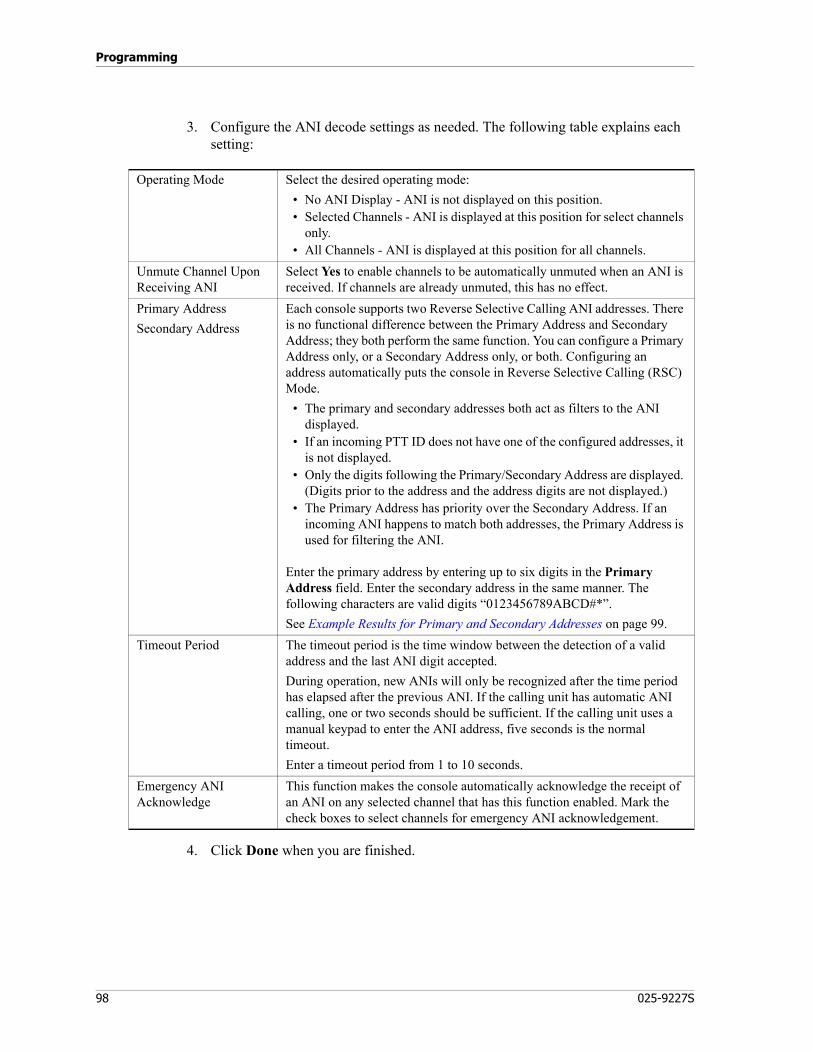
Programming
98 025-9227S
3. Configure the ANI decode settings as needed. The following table explains each setting:
4. Click Done when you are finished.
Operating Mode Select the desired operating mode:• No ANI Display - ANI is not displayed on this position.• Selected Channels - ANI is displayed at this position for select channels
only.• All Channels - ANI is displayed at this position for all channels.
Unmute Channel Upon Receiving ANI
Select Yes to enable channels to be automatically unmuted when an ANI is received. If channels are already unmuted, this has no effect.
Primary AddressSecondary Address
Each console supports two Reverse Selective Calling ANI addresses. There is no functional difference between the Primary Address and Secondary Address; they both perform the same function. You can configure a Primary Address only, or a Secondary Address only, or both. Configuring an address automatically puts the console in Reverse Selective Calling (RSC) Mode.
• The primary and secondary addresses both act as filters to the ANI displayed.
• If an incoming PTT ID does not have one of the configured addresses, it is not displayed.
• Only the digits following the Primary/Secondary Address are displayed. (Digits prior to the address and the address digits are not displayed.)
• The Primary Address has priority over the Secondary Address. If an incoming ANI happens to match both addresses, the Primary Address is used for filtering the ANI.
Enter the primary address by entering up to six digits in the Primary Address field. Enter the secondary address in the same manner. The following characters are valid digits “0123456789ABCD#*”.See Example Results for Primary and Secondary Addresses on page 99.
Timeout Period The timeout period is the time window between the detection of a valid address and the last ANI digit accepted.During operation, new ANIs will only be recognized after the time period has elapsed after the previous ANI. If the calling unit has automatic ANI calling, one or two seconds should be sufficient. If the calling unit uses a manual keypad to enter the ANI address, five seconds is the normal timeout.Enter a timeout period from 1 to 10 seconds.
Emergency ANI Acknowledge
This function makes the console automatically acknowledge the receipt of an ANI on any selected channel that has this function enabled. Mark the check boxes to select channels for emergency ANI acknowledgement.

99
CPSW Menu Structure
Table 29: Example Results for Primary and Secondary Addresses
Display Operation
The display of each position is configurable to show time of day in 12-hour or 24-hour format. Alternatively, the display can show “- - - - -” (dashes) to prevent confusion with a master site clock.
♦ To configure Display Operation
1. Click Edit, Position Configuration.2. Click Display Operation.
The Display Operation dialog window opens.3. Choose a display option.4. Click Done when you are finished.
Miscellaneous
The Miscellaneous button opens a dialog window containing miscellaneous configuration settings.
♦ To configure miscellaneous settings
1. Click Edit, Position Configuration.2. Click Miscellaneous.
The Miscellaneous dialog window opens.
Configured Addresses
Incoming PTT ID
ANI Displayed at Console
111 and 123
11155 55123777 77712311 114411155 5510166 Nothing22299 Nothing
Note The Model 4010 is able to decode only the unit identification in a PTT-ID. ANIs that are configured with fleet or group designation separated by a dash from the unit ID cannot be displayed on the 4010 LCD. Therefore, end users who have multiple fleet/group IDs need to insure that the Unit IDs assigned in one fleet/group are not duplicated in another or there may be confusion as to the source of the call.

Programming
100 025-9227S
3. Configure the miscellaneous settings as needed. The following table explains each setting:
4. Click Done when you are finished.
Saving a Configuration
Saving the configuration to disk is accomplished in the usual Windows manner (File, Save or File, Save As). The saved file contains all of the settings that have been configured, including system configuration and position configuration for all positions.
Audio Source for ‘Soft’ Transmit Keys
This option allows you to specify the transmit audio source (microphone) when a “soft” transmit key is activated. A “soft” transmit key is a programmable key which has been defined as a transmit key. Choose one of the following audio sources to assign it to ‘Soft’ transmit keys:
• Dynamic Mic - Use a deskmic connected to the D-Mic input on the console Aux Audio Connector P1, or a Gooseneck Mic connected to the 4010 Main Control Board at P12.
• Electret Mic - Use a handset or headset.• Spare Input #9 steered - Use whichever audio source that Spare Input #9 is
switched to. Spare Input #9 is the mic switch input on the headset box connector on the console back panel (J4-pin 9 on the Model 4118 and J1-pin 9 on the Model 4018).
• Hookswitch steers... - Use whichever audio source that the hookswitch is switched to. Hookswitch is the ear switch input on the headset box connector on the console back panel (J4-pin 8 on the Model 4118 and J1-pin 8 on the Model 4018).
Instant Select Key Display Mode
This option allows you to set the green LED for the selected Channel/Frequency to either flash on/off or stay constantly lit. This option changes the display behavior only; there is no operational difference.
Received ‘CALL’ light duration
Enter the number of seconds (1-60) that the console “call” light indicator remains on after the channel received audio has stopped.Since the channel call light is typically on for three seconds (set by VOX hold time) after the end of a call, the time entered here is in addition to the three seconds. For example, if you enter 12 here, the console call light indicator would remain on for 15 seconds after the end of the incoming call.
Dynamic Mic selection
This setting is used to select either a Desk Mic or Gooseneck mic when TX keys are pressed. This selection must be made if a gooseneck mic is not installed on the console.Both microphones may be used together if the console firmware is ordered with the "D-bit option" enabled. In this case the panel TX keys will source audio from the GN. The PTT switch on the Desk Mic or a Footswitch activation will source audio from the Desk Mic.
Parallel Remote Status
Enable this option to allow each console to display or follow the status of other console positions (for certain functions). For example, with Parallel Remote Status enabled, if console 1 has F1 selected for a particular channel and console 2 sets that channel to F2 for transmission, the indicator on console 1 will show F2 and the console 1 operator must re-select F1 in order to transmit on it. This option is typically enabled. By disabling Parallel Remote Status, each console will retain its own frequency selection.

101
CPSW Menu Structure
Sending a Configuration to a Console
For installations with parallel consoles, all consoles should be configured identically. If you are changing the configuration of one console, you should update all consoles.
♦ To send configuration information to a console
1. Use the supplied programming cable to connect your PC with the console:• If you have a cable with one RJ connector (P/N 709-7266 or 709-7400), use it
to connect the serial port of your computer to the COMB jack (combined data) on the console.
• If you have a cable with two RJ connectors (P/N 709-7084 or 709-7417), use it to connect the serial port of your computer to the DATA IN and DATA OUT jacks on the console (these jacks might also be named LOOP IN and LOOP OUT). The cable ends are labeled for specific ports (IN vs OUT) and must be connected correctly.
If there are existing cables already connected to any of these ports, you must temporarily remove them while programming. Before removing these existing cables, ensure they are labeled so they can be returned to the proper ports.
2. There is an unlabeled switch on the bottom of the Model 4010 used to switch the console between RUN and PROGRAM modes. Move the switch to the program position, which is towards the gooseneck MIC and away from the DATA IN, DATA OUT, and COMB jacks.The console display shows “PROGRAM”.
3. Click Send config to position.4. If previous edits to the configuration file have not been saved, you will be asked if
you want to save them now. To proceed, click whichever action you prefer.5. Click OK to begin sending the configuration settings.
The mouse cursor switches to an hourglass while CPSW is sending data.6. The download is successfully completed if the console displays “** DONE **”. If
the console does not display “** DONE **”, then some troubleshooting is required:a. If the console display shows “PROGRAM” after CPSW is done sending, then
there was a communication break between the PC and console, such as a serial cable not connected, a mismatched baud rate, or a wrong COM port configured in CPSW.
b. If the console continues to display “DnLoading CPS” long after CPSW is done sending, then the serial transfer was interrupted after it started. The cable may
Note The USB-to-serial port adapter provided by Zetron (P/N 802-0516) is tested and the recommended adapter for this application. Many third party USB-to-serial port adapters are inconsistent with their serial port implementation and do not reliably communicate with Zetron equipment.

Programming
102 025-9227S
have been disconnected or the baud rate changed in the middle of the download (Windows XP will occasionally change the baud rate by itself). There is no timeout function on the console, so it will continue to display "DnLoading CPS" until reset or switched back to 'Run' mode.
c. If the console displays “THX 084”, a checksum error occurred, and the console ignored the rest of the download. This can be caused by a baud rate change or data corruption.
7. Move the switch to the run position. The top line of the LCD should show the name of the configuration file. If the name of the file has fewer than eight characters, the LCD may display extra characters.
8. If you need to send the same configuration settings to more than one 4010 console, repeat this procedure as needed.
Warning! If the console displays “DnLoading CPS” or “THX 084” after the PC has stopped sending data, the console's key-definition database has been corrupted and the console will not work until a good CPSW database is successfully downloaded. Until the console is fixed, it will always display "CPSdataErr" when switched back to 'Run' mode and it may ignore all buttons.
Tip You can attempt to download again by toggling the console's mode switch to 'Run' and then back to 'Program'. The display will then show "PROGRAM" again and a new download from CPSW can start.
STOP

Model 4010 Dual Channel Card Layout
103
Appendix A: Model 4010 Components
Model 4010 Dual Channel Card Layout
On older boards, P1 and JP6 may be located in different positions than shown here. P2 and P3 are used to mount daughterboard such as the LOTL or Channel ANI Decoders.
For a list of jumpers and switches, see Table 4 on page 27. For a list of potentiometers, test points, and audio adjustment information, see Receive Audio Adjustment on page 42 and Transmit Audio Adjustment on page 45.
JP7
JP4
JP2
JP1
JP3
BA
B
A B
A B
A B
SW1
CA
JP6
B CA
12345678
R52
R53
R54
R9
R10
R11
P1
P2
126
P3
126
Model 4010 (P/N 702-9377)

Appendix A: Model 4010 Components
104 025-9227S
Model 4010 Main Control Board
1
1
1
1 1 1
11
11
1P9
P10
P1A
uxilia
ry A
udio
J1J5
P8
P7
J15
J14
J13
J6
1
J17
CO
MB
Dat
a In
Dat
a O
utP1
1
P12
P6
1
JP10
JP1
JP3
JP4
JP5
JP6
ABC
ABAB
AB AB
AB
ABJP7
A B C
R7
Han
dset
Ea
r
R10
4
R62
R63
R67
R68
Han
dset
/H
eads
et M
ic
R70
Dyn
amic
M
icro
phon
eR
69
Pagi
ng/F
unct
ion
Leve
l
Auxi
liary
(Ext
erna
l Lev
el)
Aler
t Lev
el
JP2
Goo
sene
ckM
icro
phon
e
Han
dset
J16
DC
Pow
er
Stan
dby
Pow
er In
put
Inpu
t
Hea
dset
Rem
ote
Term
inal
(Pho
ne P
atch
)In
terfa
ce C
ard
Spar
eIn
puts
Spar
eO
utpu
ts
JP8
5
1 5
2 42 4
2 4
U27
U29
JP9
Epr
om
Back
upR
am/B
atte
ry
To D
ispl
ayTo
Low
er K
eypa
dTo
Upp
er K
ey P
anel
U23
Proc
esso
rM
ain
U15
Gen
erat
orP
agin
g/Fu
nctio
n
1 01 4
J12
Dua
l Cha
nnel
or
Aux
I/O
Car
d
J11
Dua
l Cha
nnel
or
Aux
I/O
Car
d
J10
Dua
l Cha
nnel
or
Aux
I/O
Car
d
J9 Dua
l Cha
nnel
or
Aux
I/O
Car
d
J8 Dua
l Cha
nnel
or
Aux
I/O
Car
d
J7 Dua
l Cha
nnel
or
Aux
I/O
Car
d
SW1
Pro
gram
/Run
Sw
itch
(Bot
tom
sid
e)
J2C
hann
els
9-12
Cha
nnel
s 5-
8C
hann
els
1-4
J3J4
F1Fu
seO
pera
tor
Tone P5
P4
P3 Handset Cradle Hook Switch
Goo
sene
ck
Mic
roph
one
Model 4010 (P/N 702-9376)Model 4010R (P/N 702-9569)

105
Model 4010 Main Control Board
Model 4010 Control Board Connectors and Fuse
For a list of jumpers and switches, see Model 4010 Control Board Jumpers and Switches on page 24. For a list of pots, see Level Adjustments on page 42. For a list of connectors, see the following table.
Number Name Notes
F1 Fuse See Primary Power on page 19
J1 Headset Jackbox See Telephone/Radio Headset Interface on page 53.
J2 Channels 1-4
See Wiring to the Channels on page 31.J3 Channels 5-8
J4 Channels 9-12
J5 Power See Primary Power on page 19.
J6 Phone Patch Card See Model 4010 Phone Patch Card on page 54.
J7 - J12 Slots for Dual Channel Cards and/or Aux I/O Cards
See Table 1 on page 23 for compatibility matrix.See Configuring Dual Channel Cards on page 26.See Inputs and Outputs on page 37.
J13 COMBSee Program/Run Switch on page 18.See Cable Installation on page 69.
J14 Data In / Loop In
J15 Data Out / Loop Out
J16 3-pin auxiliary DC power connector See Auxiliary Power on page 19.
J17 Handset jack This connector is not present on the Model 4010R.See PTT Handset with Cradle on page 77.
P1 Auxiliary Audio See Auxiliary Audio on page 39.
P3 Telephone hook switch See PTT Handset with Cradle on page 77.
P4 Tone Remote connector If there is no Tone Remote Card installed, four jumpers must be installed across this connector at the following pins: 1-2, 3-4, 5-6, 7-8. Either the card or the jumpers have to be installed in order to pass Unselect, Select, Mic, and Patch audio.
P5 System Wide ANI connector If there is no System Wide ANI Card installed, a jumper must be installed across this connector at pins 1-2. Either the card or the jumper has to be installed in order to pass Select audio. (No longer available).
P6 Audio Delay connector If there is no Audio Delay Card installed, a jumper must be installed across this connector at pins 1-2. Either the card or the jumper has to be installed in order to pass Select audio. (No longer available).
P7 Spare Outputs Spare I/O may be configured in CPSW to act as Auxiliary I/O.See Inputs and Outputs on page 37.P8 Spare Inputs
P9 Upper button panel connector Connects to J1 on the button panel circuit board on the front of the console.
P10 16-Digit Keypad connector Connects to J1 on the keypad board on the front of the console.
P11 Display board connector Connects to J1 on the display board on the front of the console.
P12 Gooseneck mic connector See Gooseneck Microphone on page 48.
SW1 Program/Run switch See Program/Run Switch on page 18.
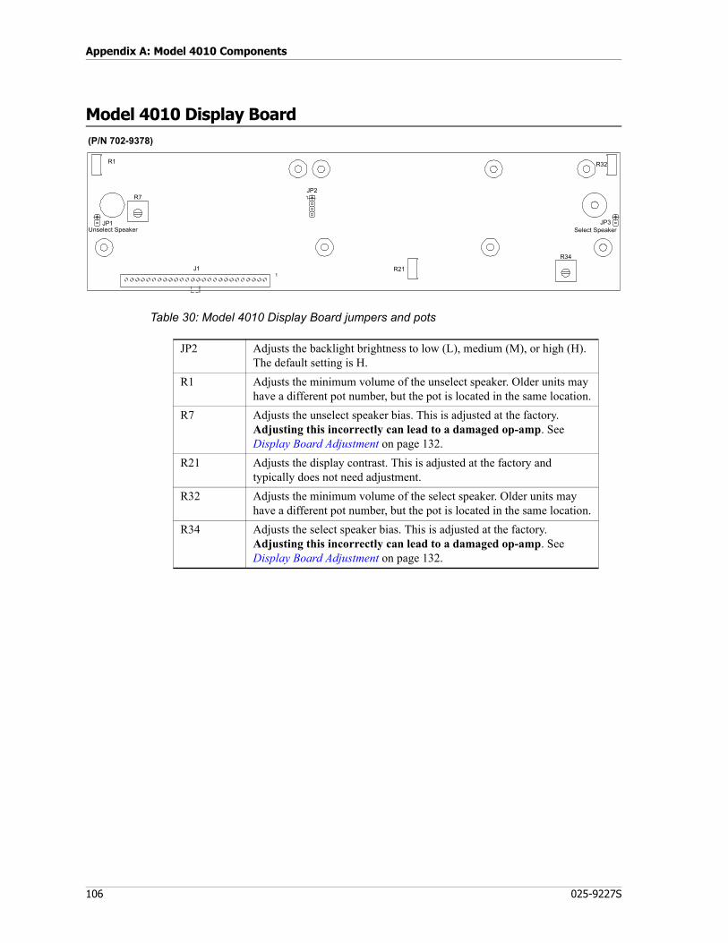
Appendix A: Model 4010 Components
106 025-9227S
Model 4010 Display Board
Table 30: Model 4010 Display Board jumpers and pots
J11
JP1Unselect Speaker
R1
1JP2
R21
JP3Select Speaker
R32
R34
R7
(P/N 702-9378)
JP2 Adjusts the backlight brightness to low (L), medium (M), or high (H). The default setting is H.
R1 Adjusts the minimum volume of the unselect speaker. Older units may have a different pot number, but the pot is located in the same location.
R7 Adjusts the unselect speaker bias. This is adjusted at the factory. Adjusting this incorrectly can lead to a damaged op-amp. See Display Board Adjustment on page 132.
R21 Adjusts the display contrast. This is adjusted at the factory and typically does not need adjustment.
R32 Adjusts the minimum volume of the select speaker. Older units may have a different pot number, but the pot is located in the same location.
R34 Adjusts the select speaker bias. This is adjusted at the factory. Adjusting this incorrectly can lead to a damaged op-amp. See Display Board Adjustment on page 132.

107
Model 4010 Tone Remote Adapter
Model 4010 Tone Remote Adapter
JP7JP6
TP2
R47
JP2 JP3 TP1JP1
1 1
1
GT
AUDIO
DELAYSEC
MIC
PATCH
DLYD
Without audio delay (P/N 702-9433)
JP1
R1
A B
With audio delay (P/N 702-9896)

Appendix A: Model 4010 Components
108 025-9227S
Table 31: Tone Remote Adapter (with audio delay) jumpers
For additional information, see Model 4010 Tone Remote System Adapter on page 62.
Jumper Position Status
Del
ay J
umpe
rs
JP1 (DELAY) .25 .25 sec delayJP1 .50 .50 sec delayJP1 .75 .75 sec delayJP1 1.0 1.0 sec delayJP2 (MIC) IN Enable delayJP2 OUT Disable delayJP3 (PATCH) IN Enable delayJP3 OUT Disable delay
Not
ch F
ilter
Jum
pers
JP7 (PATCH) IN Enable notch filterJP7 OUT Disable notch filterJP6 (MIC) IN Enable notch filterJP6 OUT Disable notch filter
The default conditions for the jumpers are in the IN position and .75 seconds for the delay setting.

109
Appendix B: CPSW Reference Material
This appendix contains reference material used for programming with CPSW (Console Programming System for Windows). See Programming on page 79.
Main topics in this appendix:• DC and Tone Remote Function Definitions on page 110• Achieving Motorola/GE DC Control Currents on page 111• Paging Format Specifications on page 112• Description of Key Functions and Parameters on page 119

Appendix B: CPSW Reference Material
110 025-9227S
DC and Tone Remote Function Definitions
Table 32: DC Remote Function Definition
Table 33: Tone Remote Function Definition
Current T1R1STD
T1R1 PAGING T2R2 T4R4
0.0 mA RX RX RX RX+2.5 mA — — — —+5.0 mA F1 — F1 F1+7.5 mA — — — —+10.0 mA — — — —+12.5 mA RPTR ON F1 W PL F2 F2+15.0 mA — — — —+15.5 mA — — — —-2.5 mA PL MON PL MON PL MON PL MON-5.0 mA RPTR OFF — R2 OFF F3-7.5 mA — — — —
-10.0 mA — — — —-12.5 mA — F1 W/O PL — F4-15.0 mA — — — —-15.5 mA — — — —
Tone Freq T1R1 T2R2 T4R4 T8R8650Hz — — — —750Hz — — — —850Hz — — — F8950Hz — — — F7
1050Hz PL4/WC 2 OFF PL4/WC 2 OFF WC 2 OFF F61150Hz PL3/WC 2 ON PL3/WC 2 ON WC 2 ON F51250Hz PL2/WC 1 OFF PL2/WC 1 OFF F4 F41350Hz PL1/WC 1 ON PL1/WC 1 ON F3 F31450Hz RPTR ON RPTR ON RPTR ON RPTR ON1550Hz RPTR OFF RPTR OFF RPTR OFF RPTR OFF1650Hz R2 ON R2 ON R2 ON R2 ON1750Hz R2 OFF R2 OFF R2 OFF R2 OFF1850Hz F1 W/O PL F2 F2 F21950Hz F1 F1 F1 F12050Hz PL MON PL MON PL MON PL MON
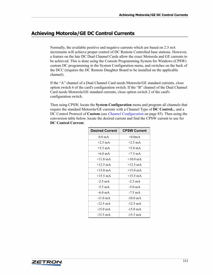
111
Achieving Motorola/GE DC Control Currents
Achieving Motorola/GE DC Control Currents
Normally, the available positive and negative currents which are based on 2.5 mA increments will achieve proper control of DC Remote Controlled base stations. However, a feature on the late DC Dual Channel Cards allow the exact Motorola and GE currents to be achieved. This is done using the Console Programming System for Windows (CPSW) custom DC programming in the System Configuration menu, and switches on the back of the DCC (requires the DC Remote Daughter Board to be installed on the applicable channel).
If the “A” channel of a Dual Channel Card needs Motorola/GE standard currents, close option switch 6 of the card's configuration switch. If the “B” channel of the Dual Channel Card needs Motorola/GE standard currents, close option switch 2 of the card's configuration switch.
Then using CPSW, locate the System Configuration menu and program all channels that require the standard Motorola/GE currents with a Channel Type of DC Control... and a DC Control Protocol of Custom (see Channel Configuration on page 85). Then using the conversion table below, locate the desired current and find the CPSW current to use for DC Control Current.
Desired Current CPSW Current
0.0 mA +0.0mA+2.5 mA +2.5 mA+5.5 mA +5.0 mA+6.0 mA +7.5 mA+11.0 mA +10.0 mA+12.5 mA +12.5 mA+15.0 mA +15.0 mA+15.5 mA +15.5 mA-2.5 mA -2.5 mA-5.5 mA -5.0 mA-6.0 mA -7.5 mA-11.0 mA -10.0 mA-12.5 mA -12.5 mA-15.0 mA -15.0 mA-15.5 mA -15.5 mA
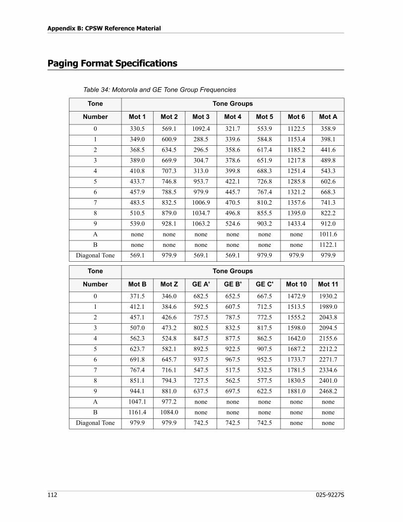
Appendix B: CPSW Reference Material
112 025-9227S
Paging Format Specifications
Table 34: Motorola and GE Tone Group Frequencies
Tone Tone Groups
Number Mot 1 Mot 2 Mot 3 Mot 4 Mot 5 Mot 6 Mot A
0 330.5 569.1 1092.4 321.7 553.9 1122.5 358.91 349.0 600.9 288.5 339.6 584.8 1153.4 398.12 368.5 634.5 296.5 358.6 617.4 1185.2 441.63 389.0 669.9 304.7 378.6 651.9 1217.8 489.84 410.8 707.3 313.0 399.8 688.3 1251.4 543.35 433.7 746.8 953.7 422.1 726.8 1285.8 602.66 457.9 788.5 979.9 445.7 767.4 1321.2 668.37 483.5 832.5 1006.9 470.5 810.2 1357.6 741.38 510.5 879.0 1034.7 496.8 855.5 1395.0 822.29 539.0 928.1 1063.2 524.6 903.2 1433.4 912.0A none none none none none none 1011.6B none none none none none none 1122.1
Diagonal Tone 569.1 979.9 569.1 569.1 979.9 979.9 979.9
Tone Tone Groups
Number Mot B Mot Z GE A' GE B' GE C' Mot 10 Mot 11
0 371.5 346.0 682.5 652.5 667.5 1472.9 1930.21 412.1 384.6 592.5 607.5 712.5 1513.5 1989.02 457.1 426.6 757.5 787.5 772.5 1555.2 2043.83 507.0 473.2 802.5 832.5 817.5 1598.0 2094.54 562.3 524.8 847.5 877.5 862.5 1642.0 2155.65 623.7 582.1 892.5 922.5 907.5 1687.2 2212.26 691.8 645.7 937.5 967.5 952.5 1733.7 2271.77 767.4 716.1 547.5 517.5 532.5 1781.5 2334.68 851.1 794.3 727.5 562.5 577.5 1830.5 2401.09 944.1 881.0 637.5 697.5 622.5 1881.0 2468.2A 1047.1 977.2 none none none none noneB 1161.4 1084.0 none none none none none
Diagonal Tone 979.9 979.9 742.5 742.5 742.5 none none

113
Paging Format Specifications
Table 35: Motorola and GE Code Plans
Pager Code Plans
Cap-code
Mot B Groups
Mot C Groups
Mot D Groups
Mot E Groups
Mot F Groups
Mot G Groups
Mot H Groups
Mot J Groups
Mot K Groups
0xx 2+4 N/A N/A N/A N/A N/A N/A N/A N/A
1xx 1+1 1+1 1+1 1+1 1+1 1+1 1+1 1+1 1+1
2xx 2+2 2+2 2+2 2+2 1+3 1+3 1+3 1+4 1+4
3xx 3+3 1+2 1+2 1+2 3+3 3+3 3+3 4+1 4+1
4xx 1+2 4+4 1+5 2+1 4+4 3+1 3+1 4+4 4+4
5xx 1+3 1+4 5+5 1+6 3+1 5+5 1+6 5+5 1+6
6xx 2+1 2+1 2+1 6+6 1+4 1+5 6+6 1+5 6+6
7xx 3+1 4+1 5+1 6+1 4+1 5+1 6+1 4+5 6+1
8xx 2+3 2+4 2+5 2+6 3+4 3+5 3+6 5+4 4+6
9xx 3+2 4+2 5+2 6+2 4+3 5+3 6+3 5+1 6+4
Groups 1-2-3-4 1-2-4 1-2-5 1-2-6 1-3-4 1-3-5 1-3-6 1-4-5 1-4-6
Mot L Groups
Mot M Groups
Mot N Groups
Mot P Groups
Mot Q Groups
Mot R Groups
Mot S Groups
Mot T Groups
Mot U Groups
0xx N/A 4+2 4+2 4+2 4+2 4+2 4+2 4+2 4+2
1xx 1+1 2+3 2+3 2+3 2+4 2+4 2+5 3+4 3+4
2xx 1+5 2+2 2+2 2+2 2+2 2+2 2+2 4+3 4+3
3xx 5+1 3+3 3+3 3+3 4+2 4+2 5+2 3+3 3+3
4xx 1+6 4+4 3+2 3+2 4+4 4+4 2+6 4+4 4+4
5xx 5+5 3+2 5+5 2+6 5+5 2+6 5+5 5+5 3+6
6xx 6+6 2+4 2+5 6+6 2+5 6+6 6+6 3+5 6+6
7xx 6+1 4+2 5+2 6+2 4+5 6+2 6+2 4+5 6+3
8xx 5+6 3+4 3+5 3+6 5+4 4+6 5+6 5+4 4+6
9xx 6+5 4+3 5+3 6+3 5+2 6+4 6+5 5+3 6+4
Groups 1-5-6 2-3-4 2-3-4-5 2-3-4-6 2-4-5 2-4-6 2-5-6 2-3-4-5 2-3-4-6
Mot V Groups
Mot W Groups
Mot Y Groups
Mot MT Groups
GE X Groups
GE Y Groups
GE Z1 Groups
SPL EXT
Groups
0xx 4+2 4+2 N/A 4+2 A'+A' B'+B' A'+A' 10+10
1xx 3+5 4+6 A+A 1+1 B'+A' C'+B' C'+A' 11+11
2xx 5+3 6+4 B+B 2+2 B'+B' C'+C' C'+C' 10+11
3xx 3+3 5+6 Z+Z 1+2 A'+B' B'+C' A'+C' 11+10
4xx 3+6 4+4 A+B 4+4 C'+C' N/A N/A 3+10
5xx 5+5 5+5 A+Z 5+5 C'+A' N/A N/A 6+10
6xx 6+6 6+6 B+A 2+1 C'+B' N/A N/A 3+11
7xx 6+3 4+5 Z+A 4+5 A'+C' N/A N/A 6+11
8xx 5+6 5+4 B+Z 5+4 B'+C' N/A N/A 10+6
9xx 6+5 6+5 Z+B 2+4 N/A N/A N/A 11+6
Groups 2-3-4-5-6 2-4-5-6 A-B-Z 1-2-4-5 A'-B'-C' B'-C' A'-C' 3-6-10-11
1. GE 100-call plan Z is tone groups C'+C'; use (100-Call format). For capcodes ending in double-digits using tone group twice, (example: 122 in code plan C), use diagonal as one of the tones.

Appendix B: CPSW Reference Material
114 025-9227S
Table 36: General Encoding Plans
Pager General Plan Modified Gen. Plan General Alternate Plan
Cap-code
ToneGroups
Diagonal Tone
ToneGroups
Diagonal Tone
Pager Capcode1
ToneGroups
0xx 4+2 N/A N/A N/A 0xx N/A1xx 1+1 569.1 1+1 569.1 1xx 953.7 + Mot 12xx 2+2 979.9 2+2 979.9 2xx 953.7 + Mot 23xx 1+2 N/A 3+3 569.1 3xx 979.9 + Mot 24xx 4+4 569.1 4+4 569.1 4xx 953.7 + Mot 45xx 5+5 979.9 5+5 979.9 5xx 953.7 + Mot 56xx 2+1 N/A 6+6 979.9 6xx 979.9 + Mot 17xx 4+5 N/A N/A N/A 7xx 979.9 + Mot 58xx 5+4 N/A N/A N/A 8xx 979.9 + Mot 49xx 2+4 N/A N/A N/A
Axx2 3+3 569.1 N/A N/A
1. For General Alternate Code Plan, the last two digits of the capcode are the same.2. The General Plan has an eleventh pager block (with Capcodes Axx), which is not coded on the console.
Tone Groups
General Plan 1, 2, 3, 4, 5Modified Gen. Plan 1, 2, 3, 4, 5, 6
Note On General and Modified General plans, there are different diagonal tones for different pager blocks.

115
Paging Format Specifications
Table 37: Reach Encoding Plan
Table 38: Zetron Tone Groups for Reach Encoding
Tone Number
Frequency(Hz)
Tone Number
Frequency(Hz)
Tone Number
Frequency(Hz)
Tone Number
Frequency(Hz)
0 3960.0 16 2274.0 32 1306.0 48 750.01 3824.0 17 2196.0 33 1261.0 49 725.02 3694.0 18 2121.0 34 1219.0 50 700.03 3568.0 19 2049.0 35 1177.0 51 676.04 3446.0 20 1980.0 36 1137.0 52 653.05 3329.0 21 1912.0 37 1098.0 53 631.06 3215.0 22 1847.0 38 1061.0 54 609.07 3106.0 23 1784.0 39 1025.0 55 588.08 3000.0 24 1723.0 40 990.0 56 568.09 2898.0 25 1664.0 41 956.0 57 549.0
10 2799.0 26 1608.0 42 923.0 58 530.011 2704.0 27 1553.0 43 892.0 59 512.012 2612.0 28 1500.0 44 862.0 60 495.013 2523.0 29 1449.0 45 832.014 2437.0 30 1400.0 46 804.015 2354.0 31 1352.0 47 776.0
Tone Tone Groups
Number Z1 Z2 Z3 Z4 Z5
0 1980.0 1177.0 1400.0 832.0 588.01 2704.0 1608.0 1912.0 1137.0 804.02 2612.0 1553.0 1847.0 1098.0 776.03 2523.0 1500.0 1784.0 1061.0 750.04 2437.0 1449.0 1723.0 1025.0 725.05 2354.0 1400.0 1664.0 990.0 700.06 2274.0 1352.0 1608.0 956.0 676.07 2196.0 1306.0 1553.0 923.0 653.08 2121.0 1261.0 1500.0 892.0 631.09 2049.0 1219.0 1449.0 862.0 609.0

Appendix B: CPSW Reference Material
116 025-9227S
Table 39: Reach Code Plan
Pager Capcode
Individual Call Tone Groups
(x+y)0yx Z5+Z31xy Z1+Z22yx Z2+Z13xy Z3+Z44yx Z4+Z35xy Z1+Z46yx Z4+Z17xy Z1+Z58yx Z5+Z19xy Z3+Z5
Note The ones/tens digit encoding, shown by “x” and “y,” reverses position for each 100 pager block. In Motorola/GE plans, the first tone is always the tens digit and the second tone is the ones digit.
For REACH group call, 0xx group is not present. Instead, ten group calls are accessible using pager numbers 000, 011, 022...099. These pager numbers generate the ten group call tones from tone group Z1. The group calls activate the first tone Z1 pagers (capcodes 1xx, 5xx, and 7xx).

117
Paging Format Specifications
Table 40: Zetron Standard Tone Sets
Table 41: DTMF Tone Pair Frequencies and Timing
Tone Set1 CCIR EEA EIA ZVEI DDZVEI DZVEI PZVEI
Tone No. 0 1981 1981 600 2400 2400 2200 2400Tone No. 1 1124 1124 741 1060 1060 970 1060Tone No. 2 1197 1197 882 1160 1160 1060 1160Tone No. 3 1275 1275 1023 1270 1270 1160 1270Tone No. 4 1358 1358 1164 1400 1400 1200 1400Tone No. 5 1446 1446 1305 1530 1530 1400 1530Tone No. 6 1540 1540 1446 1670 1670 1530 1670Tone No. 7 1640 1640 1587 1830 1830 1670 1830Tone No. 8 1747 1747 1728 2000 2000 1830 2000Tone No. 9 1860 1860 1869 2200 2200 2000 2200A Group 2400 1055 2151 2800 885 825 970C X-Tone 2247 2400 2010 970 740 2800 2800E Repeat 2110 2110 459 2600 970 2400 2600
Timing2 CCIR EEA EIA ZVEI DDZVEI DZVEI PZVEI
Preamble 673 673 673 673 673 673 673Gap 65 65 65 65 65 65 65Tone 100 40 33 70 70 70 70X-Tone 100 40 65 70 70 70 70
1. Frequencies are shown in hertz.2. Timing is shown in milliseconds
Column 1 Column 2 Column 3 Column 4
FirstRow1
1. Frequencies are shown in hertz.
16971209
2697
1336
3697
1477
A6971633
Second Row
47701209
5770
1336
6770
1477
B7701633
ThirdRow
78521209
8852
1336
9852
1477
C8521633
Fourth Row
*9411209
0941
1336
#941
1477
D9411633

Appendix B: CPSW Reference Material
118 025-9227S
Key from 16-button keypad.Timing: Variable. Typical is 150ms of tone, 50ms of silence.Digits: 1 through 14, including A, B, C, D, *, and #.
Table 42: Quick Call One (Two-Plus-Two) Frequencies and Timing
Timing: Variable.
Typical Timing:First tone pair: 1250msGap: 0msSecond tone pair: 1000msGroup call: 5000ms (if 1st and 2nd tone pairs are same)
Tone A Series B Series Z Series
No. Freq.1
1. Frequencies are shown in hertz.
Code Freq. Code Freq. Code
0 358.9 CA 371.5 CB 346.7 CZ1 398.1 DA 412.1 DB 384.6 DZ2 441.6 EA 457.1 EB 426.6 EZ3 489.8 FA 507.0 FB 473.2 FZ4 543.3 GA 562.3 GB 524.8 GZ5 602.6 HA 623.7 HB 582.1 HZ6 668.3 JA 691.8 JB 645.7 JZ7 741.3 KA 767.4 KB 716.1 KZ8 822.2 LA 851.1 LB 794.3 LZ9 912.0 MA 944.1 MB 881.0 MZA 1011.6 NA 1047.1 NB 977.2 NZB 1122.1 PA 1161.4 PB 1084.0 PZ

119
Description of Key Functions and Parameters
Description of Key Functions and Parameters
This section describes key functions and their definable parameters. Use this section as a reference when defining key functions (see To define a key on page 95).
Channel Functions
To define a channel function, you must first select the channel number. The channel must have been previously defined in System Configuration.
Select
This function will “Select” the appropriate channel for transmission when a transmit key is pressed. The received audio from the selected channel will be heard on the “Select” speaker. All other received audio will be routed to the “Unselect” speaker. All channels must have one and only one “Select” key assigned.
Answer/Hold
This key requires telephone control and thus is only available for channels 13 and 14. The key is used to answer a telephone call. Once a call is answered (telephone is off-hook), this key toggles the hold function.
Frequency Select
This key is only applicable with a tone or DC controlled radio with multiple frequency capability. By selecting this key, the desired frequency command will be sent. The current or tone will be sent to the radio in order to select the desired frequency.
Please note that “no current” is different from 0.0 ma. Selecting “0.0 ma” will cause zero milliamperes of DC control current to be sent when this command is executed. Selecting “No current” will cause the previous control current for that function to be maintained with no current change.
After selecting the receive current/tone, you must also specify a current or tone to activate the transmitter for the desired frequency.
Frequency Select with Voting
This key is identical to the frequency select function with the added feature of selecting an auxiliary input. This allows the output of a voter to indicate which frequency was voted. The red LED will be illuminated for the frequency that voted.
The input must have been previously defined before using this key.

Appendix B: CPSW Reference Material
120 025-9227S
Instant Select
Instant Select differs from the normal Select function in that after the Select is performed, a DC or Tone control function is sent. This is normally used on a multi-frequency base station to select a channel at a desired frequency. Several Instant Select keys may be assigned to a single channel even though only one can be active at a time.
Instant Select with Voting
If you chose instant select with voting, you must also pick the Auxiliary input that will receive the voter result. This input indicator will be illuminated whenever the voter picks this particular input. The input must have been previously defined using the System Configuration menu.
Instant Transmit
The Instant Transmit function will cause the transmitter on the assigned channel to activate even though the channel is not selected. The selected channel will not be affected.
Volume and Mute Keys
Volume Adjust (Knob)
The volume adjust key allows the volume of a specific channel to be set or changed at the console. Pressing the key will cause the current volume level (in percentage) to be displayed. Turning the “channel volume” knob while holding the key down will cause the volume level to be changed with the new value displayed on the console display.
Mute Adjust
This is a dual function key and is more correctly called the “Volume Adjust/Mute” (abbreviated “V-Adj. Mute”). Pressing and releasing the key causes the channel's received audio to be muted. The red light by the key will remain on while the channel is muted. Pressing again will unmute the channel. Pressing and holding this key will allow the channel volume to be set as described in the preceding paragraph, “Volume Adjust”.
Volume Up (Key)
This key is assigned to a specific channel to allow “one hand” volume adjusting. Pressing this key will cause the current volume setting to be displayed. Holding the key will cause
Note This is an indication of the voter result only. The channel is NOT selected by the voter input.
Note If the key being defined is associated with a spare input and the channel is multi-frequency tone or DC control, you will be asked to select a function tone to be used when this key is activated.
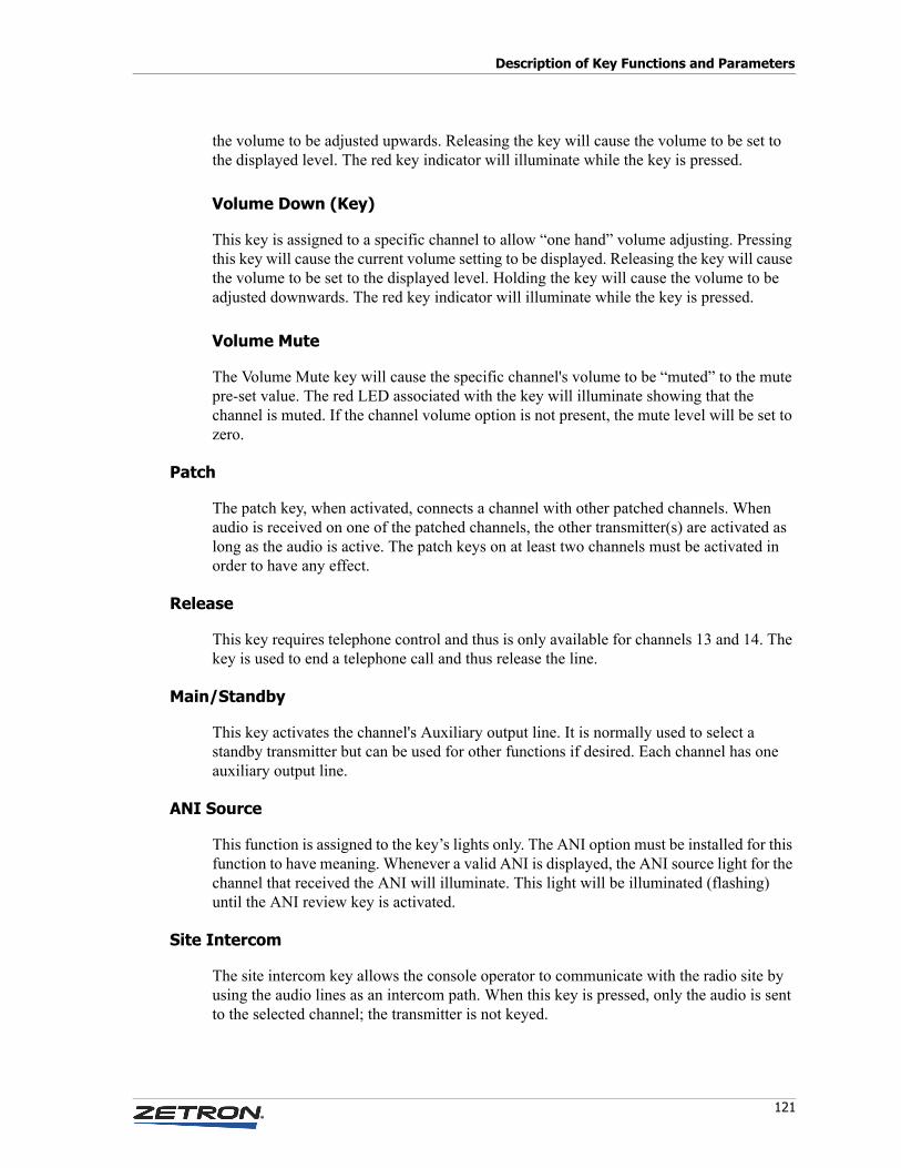
121
Description of Key Functions and Parameters
the volume to be adjusted upwards. Releasing the key will cause the volume to be set to the displayed level. The red key indicator will illuminate while the key is pressed.
Volume Down (Key)
This key is assigned to a specific channel to allow “one hand” volume adjusting. Pressing this key will cause the current volume setting to be displayed. Releasing the key will cause the volume to be set to the displayed level. Holding the key will cause the volume to be adjusted downwards. The red key indicator will illuminate while the key is pressed.
Volume Mute
The Volume Mute key will cause the specific channel's volume to be “muted” to the mute pre-set value. The red LED associated with the key will illuminate showing that the channel is muted. If the channel volume option is not present, the mute level will be set to zero.
Patch
The patch key, when activated, connects a channel with other patched channels. When audio is received on one of the patched channels, the other transmitter(s) are activated as long as the audio is active. The patch keys on at least two channels must be activated in order to have any effect.
Release
This key requires telephone control and thus is only available for channels 13 and 14. The key is used to end a telephone call and thus release the line.
Main/Standby
This key activates the channel's Auxiliary output line. It is normally used to select a standby transmitter but can be used for other functions if desired. Each channel has one auxiliary output line.
ANI Source
This function is assigned to the key’s lights only. The ANI option must be installed for this function to have meaning. Whenever a valid ANI is displayed, the ANI source light for the channel that received the ANI will illuminate. This light will be illuminated (flashing) until the ANI review key is activated.
Site Intercom
The site intercom key allows the console operator to communicate with the radio site by using the audio lines as an intercom path. When this key is pressed, only the audio is sent to the selected channel; the transmitter is not keyed.

Appendix B: CPSW Reference Material
122 025-9227S
Monitor
This key will send the correct command (current or tone) to disable the private line or channel guard feature of the radio allowing the received audio to be heard at the console. The indicator LED will remain on until the channel's transmitter is keyed.
Phone On/Off Hook
This key will activate the auxiliary output line of the designated channel. It is intended to be used as an “off hook” signal to answer an incoming phone line when the optional telephone coupler is installed. Each channel has one auxiliary output line.
Phone Hook Flash
The phone Hook Flash key will cause the On/Off Hook line to be deactivated for 500 ms thereby putting the phone on “hold”. Hit the key again to enable the phone conversation.
Extended Channel Functions
These are additional channel functions that can be assigned to Standard Tone and/or DC controlled channels.
CTCSS Select
This command activates CTCSS (constant tone coded squelch signal) over-ride. This key will cause the PL (private line) feature to be disabled thereby allowing all radio channel activity to be monitored by the console operator. Refer to DC and Tone Remote Function Definitions on page 110 for the actual tone or DC current transmitted.
Repeat On/Off
This key will toggle the radio repeater on/off function on the appropriate channel. Refer to DC and Tone Remote Function Definitions on page 110 for the actual tone or DC current transmitted.
Coded/Clear
This key will toggle the coded/clear function on the appropriate channel. Refer to DC and Tone Remote Function Definitions on page 110 for the actual tone or DC current transmitted.
Second Receiver Unmute/Mute
This key will toggle the radio Mute on/off function on the appropriate Tone controlled channel. Refer to DC and Tone Remote Function Definitions on page 110 for the actual tone transmitted.

123
Description of Key Functions and Parameters
Wild Card I On/Off
Toggle the Wild Card I function on the appropriate tone controlled radio channel. Refer to DC and Tone Remote Function Definitions on page 110 for the function actually transmitted.
Wild Card II On/Off
Toggle the Wild Card II function on the appropriate tone controlled radio channel. Refer to DC and Tone Remote Function Definitions on page 110 for the function actually transmitted.
Custom Channel Functions
The Custom Channel Functions are used to customize the channel card to the radio. Each key must have the desired transmit and receive tones or DC currents assigned.
DC
If the channel is defined as a DC controlled channel, choose the desired current for receive and transmit.
Tone
If the channel has been defined as a tone controlled channel, you will be asked to select the desired transmit and receive tone. The receive tone selected will be sent whenever the key is pressed. The transmit function will be sent on transmit.
System Functions
System functions are assigned to individual keys, but may affect more than a single channel.
Transmit Keys
The following transmit functions may be assigned to a specific key.
Normal Tx
This key will cause the selected channel(s) to transmit. This is functionally the same as the optional foot-operated PTT switch. Normally only one TX key is assigned per position.
Transfer Instant Transmit
This key, when pressed, will cause the next channel “Select” key pressed to become an “instant transmit” key for the channel. The selected channel will not change. This key is used to eliminate the need for individual Instant transmit keys on each channel.

Appendix B: CPSW Reference Material
124 025-9227S
Last Call Transmit Any Channel
This key will cause the last channel that received audio (“Call” activity) to transmit. The channel will not be selected.
Last Call Transmit Selected Channels
This key will cause the last “Selected” channel that received audio (“Call” activity) to transmit. The channel will not be selected.
Last Call Transmit Unselected Channels
This key will cause the last “Unselected” channel that received audio (“Call” activity) to transmit. The channel will not be selected.
Monitor
This key causes the programmed PL monitor current or tone to be sent to the “Selected” channel, thereby disabling the “private line” feature on the radio.
Site Intercom
The site intercom key allows the console operator to communicate with the “Selected” radio site by using the audio lines as an intercom path. When this key is pressed, only the audio is sent to the channel; the transmitter is not keyed.
Alert
Select a key to generate the desired alert tone to be transmitted to the “Selected” channel. The desired alert will be sent as long as the key is held down.
All Mute
This “All Mute” function key will cause the audio from all “Unselected” channels to be muted. The “selected” channel will be unaffected. If a muted channel is “selected”, it will be unmuted as long as it is selected. If it becomes “unselected”, it may become muted again if the “all mute” function has not been toggled.
Volume Reset
This key will cause the received audio level of the selected channel to be set to its default level, usually 51%.
Group Select
The group select key allows a set of preselected radio channels to be selected with a single key. Mark check boxes to add or delete a channel from this group key. Several group keys may be defined on a single position. A channel may be a member of several different

125
Description of Key Functions and Parameters
groups. If a channel card is not installed in the system, its channels will not show in the table.
If the channel chosen is tone or DC and is defined as a multi-frequency channel, you will be asked to select the desired function (tone or current) to be used when this key is activated.
Group Instant Tx
The group instant transmit key will cause all members of the group to be keyed with a single key. Mark check boxes to select channels for this key. A channel may be a member of several different groups. If a channel card is not installed in the system, its channels will not show in the table.
If the channel chosen is tone or DC and is defined as a multi-frequency channel, you will be asked to select the desired function (tone or current) to be used when this key is activated.
Priority Marker
To cause the priority marker to be sent when this key is pressed, click the channel number for a specific channel or click “Select” or “Transfer”. Clicking “Select” will cause the marker to be sent on the “Selected” channel. Clicking “T” will cause the marker to be sent to the channel of the next “select” key pressed.
Simultaneous Select
Holding this key and pressing channel “Select” keys will cause multiple channels to be “Selected”. All the channels thus selected will transmit when the transmit key is pressed and all their received audio will be routed to the “Select” speaker.
Speaker/Headset
When this key is programmed on the upper panel, it will cause the speaker audio to be toggled between the speakers and headset. The Green LED will indicate that the audio is routed to the speaker; the red LED will indicate the headset is receiving the audio.
When this key is programmed on the lower panel, the red LED will come on to indicate the headset is receiving audio. Pushing the key will source audio to the speakers and the LED will extinguish.
Note Jumpers are available on the console controller board to allow “Selected” or “Unselected” audio to be “locked” to the speakers or headset thus negating the function of this key.
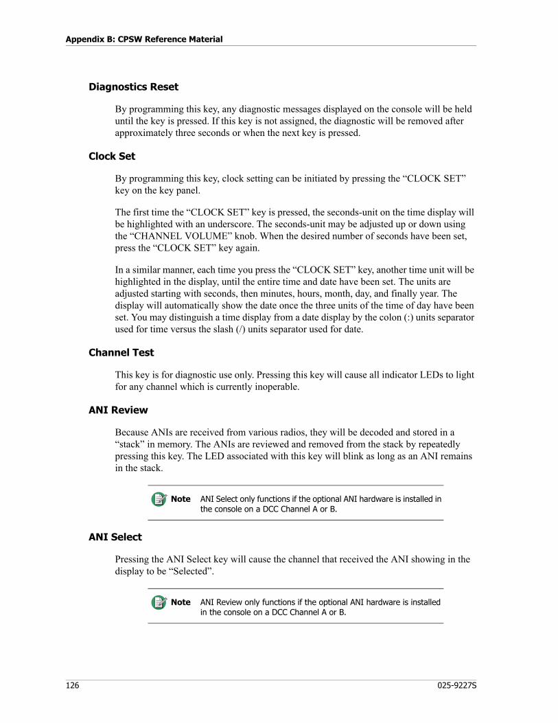
Appendix B: CPSW Reference Material
126 025-9227S
Diagnostics Reset
By programming this key, any diagnostic messages displayed on the console will be held until the key is pressed. If this key is not assigned, the diagnostic will be removed after approximately three seconds or when the next key is pressed.
Clock Set
By programming this key, clock setting can be initiated by pressing the “CLOCK SET” key on the key panel.
The first time the “CLOCK SET” key is pressed, the seconds-unit on the time display will be highlighted with an underscore. The seconds-unit may be adjusted up or down using the “CHANNEL VOLUME” knob. When the desired number of seconds have been set, press the “CLOCK SET” key again.
In a similar manner, each time you press the “CLOCK SET” key, another time unit will be highlighted in the display, until the entire time and date have been set. The units are adjusted starting with seconds, then minutes, hours, month, day, and finally year. The display will automatically show the date once the three units of the time of day have been set. You may distinguish a time display from a date display by the colon (:) units separator used for time versus the slash (/) units separator used for date.
Channel Test
This key is for diagnostic use only. Pressing this key will cause all indicator LEDs to light for any channel which is currently inoperable.
ANI Review
Because ANIs are received from various radios, they will be decoded and stored in a “stack” in memory. The ANIs are reviewed and removed from the stack by repeatedly pressing this key. The LED associated with this key will blink as long as an ANI remains in the stack.
ANI Select
Pressing the ANI Select key will cause the channel that received the ANI showing in the display to be “Selected”.
Note ANI Select only functions if the optional ANI hardware is installed in the console on a DCC Channel A or B.
Note ANI Review only functions if the optional ANI hardware is installed in the console on a DCC Channel A or B.

127
Description of Key Functions and Parameters
Paging Keys
Instant Call
An Instant Call key can have single or multiple pages (called a page stack) assigned to it. Each page in the stack can be a different format (e.g., DTMF, Two-Tone, Alert) and be steered to different channel(s).
Begin by entering a previously defined leading digit representing the desired paging format and then the page code into the Pager Code field. The maximum number of page code digits (after the leading digit) allowed is 15. This limit only affects variable length paging formats such as DTMF, Rotary, and Knox. To enter the “*” and “#” digits for these formats, use “E” and “F”, respectively.
Page Enter
This paging function is used during manual page entry (via the console DTMF/paging keypad) to terminate the entry and add the page to the stack. The use of this key is only required for variable-length paging formats (i.e., DTMF). Fixed-length paging formats (i.e., Two-Tone and Alerts) are self-terminating.
Page Clear
If manual page entry (via the console DTMF/paging keypad) is in progress, this function will abort the current key entry sequence and clear the paging display without altering the existing page stack. If a page entry is not in progress, pressing this key will delete all console page stacks. If a page transmission is in progress, it will also immediately abort the page transmission. This function should always be programmed if the console is to be used for paging.
Page Send
This paging function will terminate any manual page entry in progress (as if a PAGE ENTER key had been pressed), and begin transmitting the manual page stack on the currently selected channel(s) in the order the pages were stacked (entered). The page stack is retained and can be transmitted again (on different channel(s), for example) by pressing this key again.
Page Safety
If this function is programmed, instant-call pages will not be transmitted until this key is pressed, allowing the operator to review the selected instant-call pages before sending
Note The “Instant Call” and “Page Safety” functions represent optional features. They can always be programmed, but will generate an error message in the console if the Instant Call Paging option has not been installed.

Appendix B: CPSW Reference Material
128 025-9227S
them. If this key has not been programmed, pressing an instant-call page key will begin the page transmission immediately.
Burst Tone Select
A 1-second tone burst can be enabled by selecting a frequency from the list. This tone burst is generated for each transmit function after the transmitter is keyed-up and before the console audio is switched on. Several keys can be programmed with different frequencies. The tone burst can be disabled by selecting a key programmed with the “No Tone” choice. This feature is always disabled if no Burst Tone Select keys have been programmed.
Transfer Keys
The number of keys on a console is limited, especially for consoles with many channels. In order to reduce the number of keys used for common functions such as Volume Adjust, there are “transfer keys”. Transfer keys are used to transfer the desired function temporarily to another channel in order to save key space. By programming these keys, you can have (for example) a single Volume Adjust key usable for all channels instead of several Volume Adjust keys, one for each channel.
Phone On/Off Hook (Transfer)
This key will activate the auxiliary output line of the next channel “Selected”. It is intended for use as an “off hook” signal to answer an incoming phone line when the optional telephone is installed. Each channel has one auxiliary output line.
Phone Hook Flash (Transfer)
The phone Hook Flash key will cause the On/Off Hook line of the next channel selected to be deactivated for 500 ms thereby putting the phone on “hold”. Hit the key again to enable the phone conversation.
Volume Adjust (Transfer)
Pressing this key will cause the next “select” key pressed to become a “Volume adjust” key. This eliminates the need for a separate Volume adjusts key for each channel.
Mute Adjust (Transfer)
Pressing this key will cause the next “select” key pressed to become a “Mute/Volume adjust” key. This eliminates the need for a separate Mute Adjust key for each channel.
Auxiliary Input/Output
Auxiliary Input / Output ports have a variety of uses. Input ports can monitor alarms or show voter status. Output ports can control gates, gas pumps, video monitors, room lights and doors, even control the lawn sprinkler system.
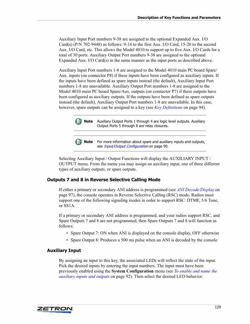
129
Description of Key Functions and Parameters
Auxiliary Input Port numbers 9-38 are assigned to the optional Expanded Aux. I/O Card(s) (P/N 702-9448) as follows: 9-14 to the first Aux. I/O Card, 15-20 to the second Aux. I/O Card, etc. This allows the Model 4010 to support up to five Aux. I/O Cards for a total of 30 ports. Auxiliary Output Port numbers 9-38 are assigned to the optional Expanded Aux. I/O Card(s) in the same manner as the input ports as described above.
Auxiliary Input Port numbers 1-8 are assigned to the Model 4010 main PC board Spare/Aux. inputs (on connector P8) if these inputs have been configured as auxiliary inputs. If the inputs have been defined as spare inputs instead (the default), Auxiliary Input Port numbers 1-8 are unavailable. Auxiliary Output Port numbers 1-8 are assigned to the Model 4010 main PC board Spare/Aux. outputs (on connector P7) if these outputs have been configured as auxiliary outputs. If the outputs have been defined as spare outputs instead (the default), Auxiliary Output Port numbers 1-8 are unavailable. In this case, however, spare outputs can be assigned to a key (see Key Definitions on page 94).
Selecting Auxiliary Input / Output Functions will display the AUXILIARY INPUT / OUTPUT menu. From the menu you may assign an auxiliary input, one of three different types of auxiliary outputs, or spare outputs.
Outputs 7 and 8 in Reverse Selective Calling Mode
If either a primary or secondary ANI address is programmed (see ANI Decode/Display on page 97), the console operates in Reverse Selective Calling (RSC) mode. Radios must support one of the following signaling modes in order to support RSC: DTMF, 5/6 Tone, or SS1A.
If a primary or secondary ANI address is programmed, and your radios support RSC, and Spare Outputs 7 and 8 are not programmed, then Spare Outputs 7 and 8 will function as follows:
• Spare Output 7: ON when ANI is displayed on the console display, OFF otherwise• Spare Output 8: Produces a 500 ms pulse when an ANI is decoded by the console
Auxiliary Input
By assigning an input to this key, the associated LEDs will reflect the state of the input. Pick the desired inputs by entering the input numbers. The input must have been previously enabled using the System Configuration menu (see To enable and name the auxiliary inputs and outputs on page 92). Then select the desired LED behavior.
Note Auxiliary Output Ports 1 through 4 are logic level outputs. Auxiliary Output Ports 5 through 8 are relay closures.
Note For more information about spare and auxiliary inputs and outputs, see Input/Output Configuration on page 90.
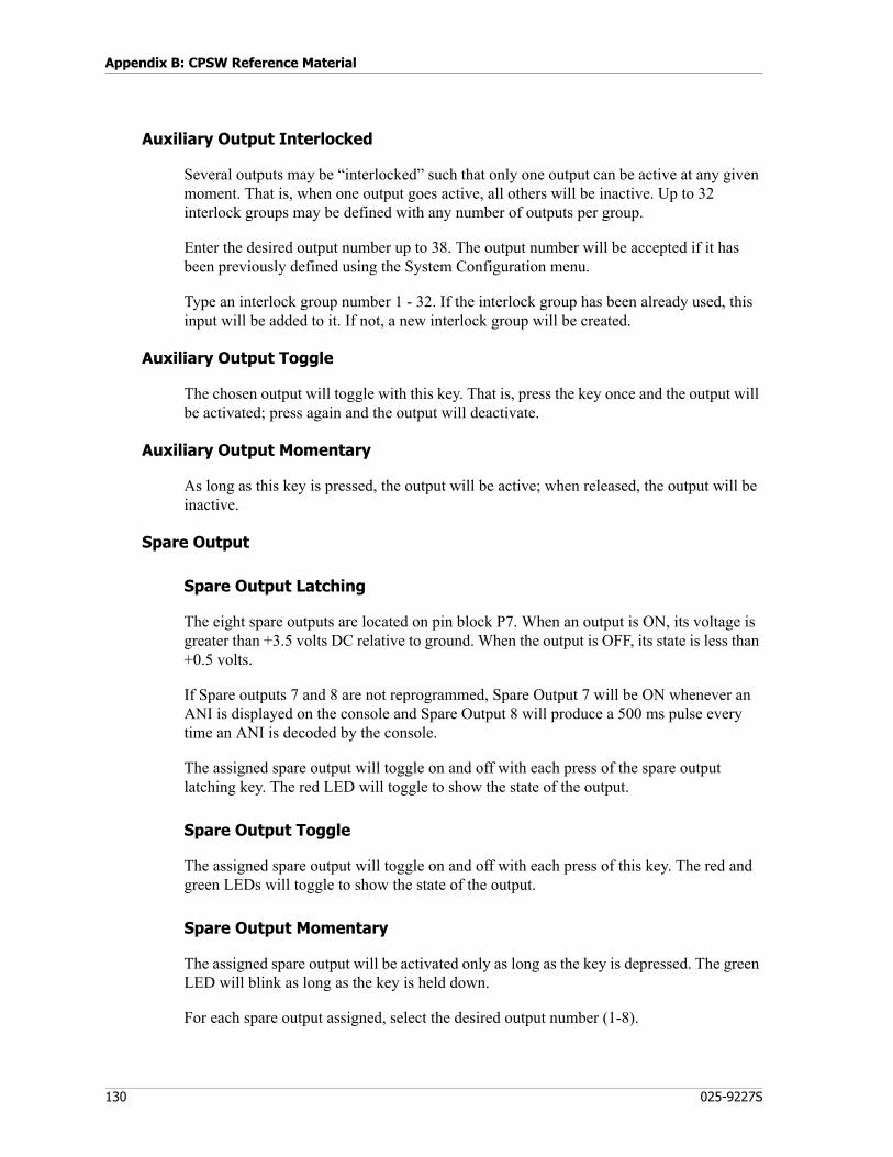
Appendix B: CPSW Reference Material
130 025-9227S
Auxiliary Output Interlocked
Several outputs may be “interlocked” such that only one output can be active at any given moment. That is, when one output goes active, all others will be inactive. Up to 32 interlock groups may be defined with any number of outputs per group.
Enter the desired output number up to 38. The output number will be accepted if it has been previously defined using the System Configuration menu.
Type an interlock group number 1 - 32. If the interlock group has been already used, this input will be added to it. If not, a new interlock group will be created.
Auxiliary Output Toggle
The chosen output will toggle with this key. That is, press the key once and the output will be activated; press again and the output will deactivate.
Auxiliary Output Momentary
As long as this key is pressed, the output will be active; when released, the output will be inactive.
Spare Output
Spare Output Latching
The eight spare outputs are located on pin block P7. When an output is ON, its voltage is greater than +3.5 volts DC relative to ground. When the output is OFF, its state is less than +0.5 volts.
If Spare outputs 7 and 8 are not reprogrammed, Spare Output 7 will be ON whenever an ANI is displayed on the console and Spare Output 8 will produce a 500 ms pulse every time an ANI is decoded by the console.
The assigned spare output will toggle on and off with each press of the spare output latching key. The red LED will toggle to show the state of the output.
Spare Output Toggle
The assigned spare output will toggle on and off with each press of this key. The red and green LEDs will toggle to show the state of the output.
Spare Output Momentary
The assigned spare output will be activated only as long as the key is depressed. The green LED will blink as long as the key is held down.
For each spare output assigned, select the desired output number (1-8).
131
Appendix C: Maintenance
Battery Check/Replacement
The Model 4010 relies on battery backup to keep the configuration stored in memory. This battery, contained within a socket, has a life expectancy of 4-7 years. Zetron recommends replacing the battery at a minimum of every 5 years. You can check the battery voltage using the following procedure, which requires a voltmeter.
♦ To check the battery
1. Power down the Model 4010 and wait at least 5 seconds.2. Locate socket U27 (see Model 4010 Dual Channel Card Layout on page 103).3. Check the voltage across pins 14 (ground) and 28 (power).4. The voltage should be 3.0vdc or greater. If the voltage is lower than 3.0vdc:
• The battery should be replaced soon.• Removing power may cause the configuration to be lost or corrupted.• You should have a backup configuration file to reprogram the console.
If the battery needs replacing, contact Zetron to order a replacement. See Model 4010 Battery Replacement Instructions (P/N 011-0789).
Firmware Upgrade
A firmware upgrade requires new parts from Zetron. The upgrade kit comes with instructions. Refer to M4010 Dispatch Console Software Upgrade Instructions(P/N 011-0422). Changing the settings or features listed in Table 3 on page 25 also require a change to the firmware.
Warning! Cards in the Model 4010 are not hotswappable. Before replacing any cards, remove power from the unit and wait five seconds.
STOP

Appendix C: Maintenance
132 025-9227S
Display Board Adjustment
The Display Board is properly adjusted at the factory and does not require further adjustment. If you replace the Display Board, use the following procedure to properly adjust the board.
♦ To adjust the display board
See Model 4010 Display Board on page 106 for a board diagram.1. Turn on the Model 4010 and check the LCD display for contrast quality. Adjust
R21 on the Display Board for the best contrast.2. Disconnect the Select Speaker from JP3.3. Connect a digital volt meter (DVM) across JP3 and adjust R34 until the DVM
reads 0.0 +/- 0.02 VDC.4. Remove the DVM and reconnect the Select Speaker to JP3.5. Disconnect the Unselect Speaker from JP1.6. Connect a digital volt meter (DVM) across JP1 and adjust R7 until the DVM reads
0.0 +/- 0.02 VDC.7. Remove the DVM and reconnect the Unselect Speaker to JP1.
Warning! An incorrect adjustment can lead to a damaged op-amp.STOP

133
Appendix D: Troubleshooting
Console LCD displays the word “PROGRAM”
The Program/Run switch is in the programming position. For normal operation it should be in the run position. Flip the switch to the other position. The switch is located on the bottom of the unit and the positions are unlabeled.
Console LCD displays “CPS Data Error”
This error message can be caused by any of the following problems:• The configuration file that you just sent to the console was not successfully
transferred, because of a serial port parameter mismatch. If you are using CPSW on Windows XP, close the application and try again. If you are using CPS, check that your serial port settings are correct (9600, N, 8, 1, no flow control).
• The battery is too weak or has died. Check the battery voltage and replace if necessary. See Battery Check/Replacement on page 131.
• The configuration is invalid. Use CPSW to send a known, valid configuration to the console. See Programming on page 79.
Scratchy or no audio on older consoles
Older consoles may suffer from oxidation on the P4 connector pins (see Model 4010 Dual Channel Card Layout on page 103). A short-term fix is to remove the Tone Remote System Adapter, clean the P4 pins, and reseat the adapter. A long-term fix is available in the form of a gold-pin upgrade. Contact Zetron for more information.
Erratic behavior on 4-year or older consoles
Check the battery. See Battery Check/Replacement on page 131.
Certain types of audio no longer occur when some options are removed
See P4, P5, and P6 in Model 4010 Control Board Connectors and Fuse on page 105.

Appendix D: Troubleshooting
134 025-9227S

Index
135
Index
Numerics4010R, 10
AAlert button, 124All Mute button, 124ANI Decode/Display, 97ANI Review button, 126ANI Select button, 126ANI Source button, 121Answer/Hold button, 119Audio Controls, 96Audio Levels, 42Auxiliary audio input adjustment, 44Auxiliary Audio, 39Auxiliary I/O Card, 56Auxiliary Input button, 129Auxiliary Input/Output, 128Auxiliary Output Interlock, 130Auxiliary Output Momentary button, 130Auxiliary Output Toggle button, 130Auxiliary Output wiring, 32
BBattery Check/Replacement, 131Burst Tone Select, 128Busy Transmit Inhibit, 28Button labeling, 39
CChannel ANI Decoder, 67Channel Configuration, 85Channel Cross-Mute, 29
Channel Functions, 119Custom, 123Extended, 122
Channel Test button, 126Channel VOX Hang Time, 30Channel Wiring, 31Clock Set button, 126Coded/Clear button, 122Connectors, 105Console Programming, 79Control Board jumpers and switches, 24CPS, 79CPSW, 79CPSW Menu Structure, 81Cradle, 77Cross-Busy I/O wiring, 32CTCSS Select button, 122Custom Calls, 89Custom Channel Functions, 123
DDC Control Constant, 86DC Control Momentary, 86DC Control, 26DC Current Calibration, 65DC Current Control, 29DC Function Definitions, 110DC Remote Daughter Board, 64Desk Microphone, 49desktop microphone, 49Diagnostics Reset button, 126Display Board
4010, 106Display Operation, 99

Index
136 025-9227S
DTMF frequencies and timing, 117Dual Channel Card jumpers and switches, 27Dual Channel Card Layout, 103Dual Channel Cards, 26
EEquivalent Circuits wiring, 33Extended Channel Functions, 122
FFirmware Upgrade, 131Footswitch, 50Frequency Select button, 119Frequency Select with Voting button, 119Full duplex operation, 29Function Definitions, 110Fuse, 105
GGE code plans, 113GE DC Control Currents, 111GE tone group frequencies, 112General encoding plans, 114GE-Star Decoder, 72Gooseneck Microphone, 48Grounding, 20Group Instant Tx button, 125Group Select button, 124
HHeadset Jackbox, 50HLGT, 93HLGT Duration, 29
II/O, 37I/O Configuration, 90Input/Output Configuration, 90Inputs, 37Inputs and Outputs, 37Installation Sequence, 15Instant Call button, 127Instant Select button, 120Instant Select with Voting button, 120Instant Transmit button, 120
JJackbox, 50
KKey Definitions, 94Key Functions and Parameters, 119
LLabeling, 39Last Call Transmit Any Channel button, 124Last Call Transmit Selected Channels button,
124Last Call Transmit Unselected Channels button,
124Level Adjustments, 42Line Termination, 28Local (E&M) Control, 86Local Control, 26Logging Recorder wiring, 31Loop address, 40Loop address jumpers, 40LOTL, 29, 65
MMain Control Board, 104Main/Standby button, 121MIC (desk), 49MIC (gooseneck), 48MIC levels, 43Microphone adjustments, 43microphone, desktop, 49Miscellaneous Options, 99Model 4115B Connections, 40Model 4115B Console Expander, 11Monitor button, 122, 124Motorola code plans, 113Motorola DC Control Currents, 111Motorola tone group frequencies, 112Mute Adjust (Transfer) button, 128Mute Adjust button, 120
NNormal Tx button, 123
137
Index
OOff-Hook Control, 53Option Codes, 25Outputs, 38Overview, 14
PPage Clear button, 127Page Enter button, 127Page Safety button, 127Page Send button, 127Paging Format Configuration, 88Paging Format Specifications
DTMF, 117General encoding plans, 114Motorola and GE code plans, 113Motorola and GE tone group frequencies,
112Reach code plan, 116Reach encoding plan, 115Zetron tone groups for Reach encoding, 115Zetron tone sets, 117
Paging Format Specifications, 112Paging Keys, 127Parallel Status Option, 69Patch button, 121Phone Hook Flash (Transfer) button, 128Phone Hook Flash button, 122Phone On/Off Hook (Transfer) button, 128Phone On/Off Hook button, 122Phone Patch Card, 54Position Layout, 94Power, 19Power Requirements, 13Priority Marker, 92Priority Marker button, 125Program/Run Switch, 18Programming, 79PTT Handset, 77PTT wiring, 31Punch-Down Block, 35, 36, 61
QQuick Call One (Two-Plus-Two) Frequencies
and Timing, 118
RReach encoding, 115Receive audio adjustment, 42Receive Audio wiring, 32Release button, 121Repeat On/Off button, 122Reverse Selective Calling Mode, 129RX level adjustment, 42
SSecond Receiver Unmute/Mute button, 122Secondary Headset Jackbox, 50Select button, 119Simplex operation, 29Simultaneous Select button, 125Site Intercom button, 121, 124Slot Mapping, 21, 23Spare Output, 130Spare Output Latching button, 130Speaker minimum audio level, 44Speaker/Headset button, 125Specifications, 12Startup, 41System check, 41System Functions, 123System Layout, 10
TT1R1 With Paging, 86T1R1 Without Paging, 86T2-2R Base Station, 75T2R2/T22R With PL, 86T2R2/T22R Without PL, 86T4R4 Without PL, 87T8R8, 87Telephone Control, 86Telephone Radio Headset Interface, 53Tone Control, 29, 86Tone Control, 26Tone level adjustments, 45Tone LOTL Daughter Board, 66Tone Remote Adapter, 107Tone Remote Function Definitions, 110Tone Remote System Adapter, 62Transfer Instant Transmit button, 123Transfer Keys, 128Transmit audio adjustment, 45
Index
138 025-9227S
Transmit Audio wiring, 32Transmit Keys, 123Transmit Timeout, 92TRHI, 53Troubleshooting, 133TX Timeout, 92
VVolume Adjust (Knob), 120Volume Adjust (Transfer) button, 128
Volume Adjust button, 120Volume and Mute Keys, 120Volume Down button, 121Volume Mute button, 121Volume Reset button, 124Volume Up button, 120
WWild Card I On/Off button, 123Wild Card II On/Off button, 123